EP2241803B1 - High power LED-lamp for spot illumination - Google Patents
High power LED-lamp for spot illumination Download PDFInfo
- Publication number
- EP2241803B1 EP2241803B1 EP10171923.5A EP10171923A EP2241803B1 EP 2241803 B1 EP2241803 B1 EP 2241803B1 EP 10171923 A EP10171923 A EP 10171923A EP 2241803 B1 EP2241803 B1 EP 2241803B1
- Authority
- EP
- European Patent Office
- Prior art keywords
- light emitting
- emitting diode
- lamp
- diode assembly
- lamp according
- Prior art date
- Legal status (The legal status is an assumption and is not a legal conclusion. Google has not performed a legal analysis and makes no representation as to the accuracy of the status listed.)
- Expired - Lifetime
Links
- 238000005286 illumination Methods 0.000 title claims description 5
- 239000000758 substrate Substances 0.000 claims description 14
- 239000004020 conductor Substances 0.000 claims description 7
- 238000004891 communication Methods 0.000 claims description 6
- 229920006395 saturated elastomer Polymers 0.000 claims description 2
- 241000219739 Lens Species 0.000 description 9
- 238000005516 engineering process Methods 0.000 description 4
- 239000000463 material Substances 0.000 description 4
- 229910052751 metal Inorganic materials 0.000 description 4
- 239000002184 metal Substances 0.000 description 4
- 239000000853 adhesive Substances 0.000 description 3
- 230000001070 adhesive effect Effects 0.000 description 3
- 230000003287 optical effect Effects 0.000 description 3
- 229910000679 solder Inorganic materials 0.000 description 3
- 239000004593 Epoxy Substances 0.000 description 2
- 238000006243 chemical reaction Methods 0.000 description 2
- 239000003086 colorant Substances 0.000 description 2
- 238000010438 heat treatment Methods 0.000 description 2
- 230000003278 mimic effect Effects 0.000 description 2
- 230000004075 alteration Effects 0.000 description 1
- 229910052782 aluminium Inorganic materials 0.000 description 1
- XAGFODPZIPBFFR-UHFFFAOYSA-N aluminium Chemical compound [Al] XAGFODPZIPBFFR-UHFFFAOYSA-N 0.000 description 1
- 229910010293 ceramic material Inorganic materials 0.000 description 1
- 238000001816 cooling Methods 0.000 description 1
- 125000003700 epoxy group Chemical group 0.000 description 1
- 238000007710 freezing Methods 0.000 description 1
- 230000008014 freezing Effects 0.000 description 1
- 238000012986 modification Methods 0.000 description 1
- 230000004048 modification Effects 0.000 description 1
- 230000035515 penetration Effects 0.000 description 1
- 229920000647 polyepoxide Polymers 0.000 description 1
Images


Classifications
-
- F—MECHANICAL ENGINEERING; LIGHTING; HEATING; WEAPONS; BLASTING
- F21—LIGHTING
- F21V—FUNCTIONAL FEATURES OR DETAILS OF LIGHTING DEVICES OR SYSTEMS THEREOF; STRUCTURAL COMBINATIONS OF LIGHTING DEVICES WITH OTHER ARTICLES, NOT OTHERWISE PROVIDED FOR
- F21V19/00—Fastening of light sources or lamp holders
- F21V19/0005—Fastening of light sources or lamp holders of sources having contact pins, wires or blades, e.g. pinch sealed lamp
-
- F—MECHANICAL ENGINEERING; LIGHTING; HEATING; WEAPONS; BLASTING
- F21—LIGHTING
- F21V—FUNCTIONAL FEATURES OR DETAILS OF LIGHTING DEVICES OR SYSTEMS THEREOF; STRUCTURAL COMBINATIONS OF LIGHTING DEVICES WITH OTHER ARTICLES, NOT OTHERWISE PROVIDED FOR
- F21V29/00—Protecting lighting devices from thermal damage; Cooling or heating arrangements specially adapted for lighting devices or systems
- F21V29/50—Cooling arrangements
- F21V29/70—Cooling arrangements characterised by passive heat-dissipating elements, e.g. heat-sinks
- F21V29/74—Cooling arrangements characterised by passive heat-dissipating elements, e.g. heat-sinks with fins or blades
-
- F—MECHANICAL ENGINEERING; LIGHTING; HEATING; WEAPONS; BLASTING
- F21—LIGHTING
- F21K—NON-ELECTRIC LIGHT SOURCES USING LUMINESCENCE; LIGHT SOURCES USING ELECTROCHEMILUMINESCENCE; LIGHT SOURCES USING CHARGES OF COMBUSTIBLE MATERIAL; LIGHT SOURCES USING SEMICONDUCTOR DEVICES AS LIGHT-GENERATING ELEMENTS; LIGHT SOURCES NOT OTHERWISE PROVIDED FOR
- F21K9/00—Light sources using semiconductor devices as light-generating elements, e.g. using light-emitting diodes [LED] or lasers
- F21K9/20—Light sources comprising attachment means
- F21K9/23—Retrofit light sources for lighting devices with a single fitting for each light source, e.g. for substitution of incandescent lamps with bayonet or threaded fittings
- F21K9/233—Retrofit light sources for lighting devices with a single fitting for each light source, e.g. for substitution of incandescent lamps with bayonet or threaded fittings specially adapted for generating a spot light distribution, e.g. for substitution of reflector lamps
-
- F—MECHANICAL ENGINEERING; LIGHTING; HEATING; WEAPONS; BLASTING
- F21—LIGHTING
- F21V—FUNCTIONAL FEATURES OR DETAILS OF LIGHTING DEVICES OR SYSTEMS THEREOF; STRUCTURAL COMBINATIONS OF LIGHTING DEVICES WITH OTHER ARTICLES, NOT OTHERWISE PROVIDED FOR
- F21V29/00—Protecting lighting devices from thermal damage; Cooling or heating arrangements specially adapted for lighting devices or systems
- F21V29/50—Cooling arrangements
- F21V29/70—Cooling arrangements characterised by passive heat-dissipating elements, e.g. heat-sinks
- F21V29/74—Cooling arrangements characterised by passive heat-dissipating elements, e.g. heat-sinks with fins or blades
- F21V29/76—Cooling arrangements characterised by passive heat-dissipating elements, e.g. heat-sinks with fins or blades with essentially identical parallel planar fins or blades, e.g. with comb-like cross-section
- F21V29/767—Cooling arrangements characterised by passive heat-dissipating elements, e.g. heat-sinks with fins or blades with essentially identical parallel planar fins or blades, e.g. with comb-like cross-section the planes containing the fins or blades having directions perpendicular to the light emitting axis
-
- F—MECHANICAL ENGINEERING; LIGHTING; HEATING; WEAPONS; BLASTING
- F21—LIGHTING
- F21V—FUNCTIONAL FEATURES OR DETAILS OF LIGHTING DEVICES OR SYSTEMS THEREOF; STRUCTURAL COMBINATIONS OF LIGHTING DEVICES WITH OTHER ARTICLES, NOT OTHERWISE PROVIDED FOR
- F21V29/00—Protecting lighting devices from thermal damage; Cooling or heating arrangements specially adapted for lighting devices or systems
- F21V29/50—Cooling arrangements
- F21V29/70—Cooling arrangements characterised by passive heat-dissipating elements, e.g. heat-sinks
- F21V29/74—Cooling arrangements characterised by passive heat-dissipating elements, e.g. heat-sinks with fins or blades
- F21V29/77—Cooling arrangements characterised by passive heat-dissipating elements, e.g. heat-sinks with fins or blades with essentially identical diverging planar fins or blades, e.g. with fan-like or star-like cross-section
- F21V29/773—Cooling arrangements characterised by passive heat-dissipating elements, e.g. heat-sinks with fins or blades with essentially identical diverging planar fins or blades, e.g. with fan-like or star-like cross-section the planes containing the fins or blades having the direction of the light emitting axis
-
- F—MECHANICAL ENGINEERING; LIGHTING; HEATING; WEAPONS; BLASTING
- F21—LIGHTING
- F21V—FUNCTIONAL FEATURES OR DETAILS OF LIGHTING DEVICES OR SYSTEMS THEREOF; STRUCTURAL COMBINATIONS OF LIGHTING DEVICES WITH OTHER ARTICLES, NOT OTHERWISE PROVIDED FOR
- F21V29/00—Protecting lighting devices from thermal damage; Cooling or heating arrangements specially adapted for lighting devices or systems
- F21V29/50—Cooling arrangements
- F21V29/70—Cooling arrangements characterised by passive heat-dissipating elements, e.g. heat-sinks
- F21V29/80—Cooling arrangements characterised by passive heat-dissipating elements, e.g. heat-sinks with pins or wires
- F21V29/81—Cooling arrangements characterised by passive heat-dissipating elements, e.g. heat-sinks with pins or wires with pins or wires having different shapes, lengths or spacing
-
- H—ELECTRICITY
- H01—ELECTRIC ELEMENTS
- H01L—SEMICONDUCTOR DEVICES NOT COVERED BY CLASS H10
- H01L25/00—Assemblies consisting of a plurality of individual semiconductor or other solid state devices ; Multistep manufacturing processes thereof
- H01L25/03—Assemblies consisting of a plurality of individual semiconductor or other solid state devices ; Multistep manufacturing processes thereof all the devices being of a type provided for in the same subgroup of groups H01L27/00 - H01L33/00, or in a single subclass of H10K, H10N, e.g. assemblies of rectifier diodes
- H01L25/04—Assemblies consisting of a plurality of individual semiconductor or other solid state devices ; Multistep manufacturing processes thereof all the devices being of a type provided for in the same subgroup of groups H01L27/00 - H01L33/00, or in a single subclass of H10K, H10N, e.g. assemblies of rectifier diodes the devices not having separate containers
- H01L25/075—Assemblies consisting of a plurality of individual semiconductor or other solid state devices ; Multistep manufacturing processes thereof all the devices being of a type provided for in the same subgroup of groups H01L27/00 - H01L33/00, or in a single subclass of H10K, H10N, e.g. assemblies of rectifier diodes the devices not having separate containers the devices being of a type provided for in group H01L33/00
- H01L25/0753—Assemblies consisting of a plurality of individual semiconductor or other solid state devices ; Multistep manufacturing processes thereof all the devices being of a type provided for in the same subgroup of groups H01L27/00 - H01L33/00, or in a single subclass of H10K, H10N, e.g. assemblies of rectifier diodes the devices not having separate containers the devices being of a type provided for in group H01L33/00 the devices being arranged next to each other
-
- H—ELECTRICITY
- H01—ELECTRIC ELEMENTS
- H01L—SEMICONDUCTOR DEVICES NOT COVERED BY CLASS H10
- H01L33/00—Semiconductor devices with at least one potential-jump barrier or surface barrier specially adapted for light emission; Processes or apparatus specially adapted for the manufacture or treatment thereof or of parts thereof; Details thereof
- H01L33/48—Semiconductor devices with at least one potential-jump barrier or surface barrier specially adapted for light emission; Processes or apparatus specially adapted for the manufacture or treatment thereof or of parts thereof; Details thereof characterised by the semiconductor body packages
- H01L33/64—Heat extraction or cooling elements
- H01L33/642—Heat extraction or cooling elements characterized by the shape
-
- F—MECHANICAL ENGINEERING; LIGHTING; HEATING; WEAPONS; BLASTING
- F21—LIGHTING
- F21V—FUNCTIONAL FEATURES OR DETAILS OF LIGHTING DEVICES OR SYSTEMS THEREOF; STRUCTURAL COMBINATIONS OF LIGHTING DEVICES WITH OTHER ARTICLES, NOT OTHERWISE PROVIDED FOR
- F21V7/00—Reflectors for light sources
- F21V7/0083—Array of reflectors for a cluster of light sources, e.g. arrangement of multiple light sources in one plane
-
- F—MECHANICAL ENGINEERING; LIGHTING; HEATING; WEAPONS; BLASTING
- F21—LIGHTING
- F21V—FUNCTIONAL FEATURES OR DETAILS OF LIGHTING DEVICES OR SYSTEMS THEREOF; STRUCTURAL COMBINATIONS OF LIGHTING DEVICES WITH OTHER ARTICLES, NOT OTHERWISE PROVIDED FOR
- F21V7/00—Reflectors for light sources
- F21V7/04—Optical design
- F21V7/041—Optical design with conical or pyramidal surface
-
- F—MECHANICAL ENGINEERING; LIGHTING; HEATING; WEAPONS; BLASTING
- F21—LIGHTING
- F21V—FUNCTIONAL FEATURES OR DETAILS OF LIGHTING DEVICES OR SYSTEMS THEREOF; STRUCTURAL COMBINATIONS OF LIGHTING DEVICES WITH OTHER ARTICLES, NOT OTHERWISE PROVIDED FOR
- F21V7/00—Reflectors for light sources
- F21V7/04—Optical design
- F21V7/06—Optical design with parabolic curvature
-
- F—MECHANICAL ENGINEERING; LIGHTING; HEATING; WEAPONS; BLASTING
- F21—LIGHTING
- F21Y—INDEXING SCHEME ASSOCIATED WITH SUBCLASSES F21K, F21L, F21S and F21V, RELATING TO THE FORM OR THE KIND OF THE LIGHT SOURCES OR OF THE COLOUR OF THE LIGHT EMITTED
- F21Y2113/00—Combination of light sources
- F21Y2113/10—Combination of light sources of different colours
- F21Y2113/13—Combination of light sources of different colours comprising an assembly of point-like light sources
-
- F—MECHANICAL ENGINEERING; LIGHTING; HEATING; WEAPONS; BLASTING
- F21—LIGHTING
- F21Y—INDEXING SCHEME ASSOCIATED WITH SUBCLASSES F21K, F21L, F21S and F21V, RELATING TO THE FORM OR THE KIND OF THE LIGHT SOURCES OR OF THE COLOUR OF THE LIGHT EMITTED
- F21Y2115/00—Light-generating elements of semiconductor light sources
- F21Y2115/10—Light-emitting diodes [LED]
-
- H—ELECTRICITY
- H01—ELECTRIC ELEMENTS
- H01L—SEMICONDUCTOR DEVICES NOT COVERED BY CLASS H10
- H01L2224/00—Indexing scheme for arrangements for connecting or disconnecting semiconductor or solid-state bodies and methods related thereto as covered by H01L24/00
- H01L2224/01—Means for bonding being attached to, or being formed on, the surface to be connected, e.g. chip-to-package, die-attach, "first-level" interconnects; Manufacturing methods related thereto
- H01L2224/42—Wire connectors; Manufacturing methods related thereto
- H01L2224/47—Structure, shape, material or disposition of the wire connectors after the connecting process
- H01L2224/48—Structure, shape, material or disposition of the wire connectors after the connecting process of an individual wire connector
- H01L2224/4805—Shape
- H01L2224/4809—Loop shape
- H01L2224/48091—Arched
-
- Y—GENERAL TAGGING OF NEW TECHNOLOGICAL DEVELOPMENTS; GENERAL TAGGING OF CROSS-SECTIONAL TECHNOLOGIES SPANNING OVER SEVERAL SECTIONS OF THE IPC; TECHNICAL SUBJECTS COVERED BY FORMER USPC CROSS-REFERENCE ART COLLECTIONS [XRACs] AND DIGESTS
- Y10—TECHNICAL SUBJECTS COVERED BY FORMER USPC
- Y10S—TECHNICAL SUBJECTS COVERED BY FORMER USPC CROSS-REFERENCE ART COLLECTIONS [XRACs] AND DIGESTS
- Y10S362/00—Illumination
- Y10S362/80—Light emitting diode
Definitions
- the present invention relates generally to light emitting diode (LED) technology for spot module illumination applications.
- LED light emitting diode
- halogen-type lamps for miniature reflector (MR) and parabolic reflector (PAR) type lamp illumination.
- MR miniature reflector
- PAR parabolic reflector
- halogen-type lamps for spot lighting, however, has some drawbacks. For example, excessive heating can limit the usage of these types of lamps for commercial and consumer applications.
- LED solutions have utilized standard, off-the-shelf, epoxy encapsulated, through hole LED sources in the light source array. Such configurations severely limit the output intensity of the lamp. Therefore, the potential market penetration that may be realized by LED technology is correspondingly limited.
- LED-based lamps have been designed to mimic the MR lamp footprint. However, because the LEDs used to construct these lamps are not thermally conductive, the thermal resistivity of such lamps being about 300°C/W, these LED lamps produce excessive heat. Therefore, thermal loading is a critical issue for conventional LED-based MR lamps.
- PCB printed circuit board
- JP H05-218510 discloses an outdoor dial LED-lamp comprising a plurality of light emitting diodes mounted onto a thermally conductive substrate oriented in a first plane, a heat spreader in thermal communication with the light emitting diode assembly and extending in a direction away from the rearward facing side of the light emitting diode assembly, and a case including a plurality of fins oriented in additional planes which are parallel to the first plane.
- JP 2000-031546 , US 4733335 , and EP 0202335 respectively disclose an LED-module, a vehicular LED-lamp, and an LED signal light comprising a plurality of light emitting diodes mounted onto a thermally conductive substrate oriented in a first plane, and a heat radiator including a plurality of fins oriented in additional planes which are perpendicular to the first plane.
- the present invention provides a new and improved apparatus which overcomes the above-referenced problems and others.
- a lamp according to claim 1 for use in connection with spot module platforms.
- the lamp includes a plurality of LEDs arranged in an LED assembly having opposing forward and rearward facing sides. The forward facing side selectively provides illumination from the LEDs when power is supplied thereto.
- a heat sink is in thermal communication with the rearward facing side of the LED assembly, and it is arranged to draw heat from the LEDs.
- Heat dissipating means is in thermal communication with the heat sink, and it dissipates heat from the heat sink via convection.
- One advantage of the present invention is that it will reduce the thermal resistivity of LED-based spot modules in MR or PAR-type lamps.
- Another advantage of the present invention is that it makes possible the use of high powered LEDs within spot modules in MR or PAR-type lamps.
- the number of LEDs in the array may vary as desired for particular applications.
- Another advantage of the present invention is that it produces an LED-based lamp that has the footprint of conventional MR lamps.
- the same approach can also be used in the case of PAR-type lamps.
- Another advantage of the present invention is that it produces brightness levels that surpass conventional clip-on filtered MR lamps.
- Another advantage of the present invention is that either primary or a combination of primary and secondary lens configurations may be used to focus the light output to provide angular output from the spot module ranging from 10° to 65° full-width-half-maximum.
- Another advantage of the present invention is that the operating temperature of the LED is reduced, thus increasing the operating lifetime of the LED based lamp.
- the invention may take form in various components and arrangements of components, and in various steps and arrangements of steps.
- the drawings are only for purposes of illustrating a preferred embodiment and are not to be construed as limiting the invention.
- a device 8 not forming part of the present invention includes an integrated array of high power LEDs 10, 12, 14 mounted to respective electrically insulative submounts 20, 22, 24.
- the submounts 20, 22, 24 are secured to a metallic, rear side substrate 26 within respective wells 30, 32, 34.
- the LEDs 10, 12, 14 are directly secured to the metallic substrate 26, thereby eliminating the use of submounts.
- the wells 30, 32, 34 in which the LEDs 10, 12, 14 reside are typically stamped or drilled directly into the substrate material to preferably form "reflector" shapes.
- other LED and well configurations are also contemplated.
- the submounts 20, 22, 24 (or optionally the LEDs 10, 12, 14 ) are secured to the rear side substrate 26, which acts as a heatsink, via a highly thermally conductive material (e.g., solder, filled epoxies, heat tape and/or other thermally advantageous adhesives).
- the LEDs 10, 12, 14 are connected to electrical contacts 36 via conductors 38.
- Lenses 40, 42, 44 cover the respective LEDs 10, 12, 14.
- a cap including a secondary optical lensing array is secured over the LEDs in the wells.
- the respective lenslets within the lensing array are mapped in a one-to-one relationship to the LEDs and the wells.
- the substrate 26 is secured to a heat spreader 60, which includes a thermally conductive material such as metal.
- a thermally conductive material such as metal.
- the spreader 60 is secured to a thermally conductive core 62.
- Thermally conductive fins 64 surround and extend from the core 62.
- the fins 64 form an independent assembly that is interference fit with the core 62.
- a tight interference fit is ensured by shrinking the core 62 and expanding the fins 64 prior to assembly.
- the core's outer diameter is temporarily shrunk by cooling (e.g., freezing) the core 62 and the inner diameter of the heatsink fins 64 is temporarily expanded by heating the fins 64. Then, the fin assembly is slid or otherwise positioned around the core 62. Once the parts return to an ambient temperature, a tight interference fit is created between the fin assembly and the core 62. Because the fins 64 contact the core 62, heat is conducted from the core to the external environment via the fins 64. Alternately, the heat spreader 60 and finned heat sink 64 may be cast as a single piece of thermally conductive material.
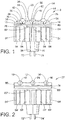
- FIGURE 2 illustrates an embodiment of the present invention
- FIGURES 3-5 illustrate further examples not forming part of the present invention.
- Components in FIGURES 2-5 that correspond to the respective components of the example illustrated in FIGURE 1 are given the same numerical references followed by a primed (') symbol. New components are designated by new numerals.
- a device 77 includes a substantially flat substrate 78, onto which the high power LEDs 10', 12', 14' are mounted.
- a cover 80 is secured over the substrate 78.
- the cover includes recesses 82, 84, 86 that map in a one-to-one relationship to the LEDs 10', 12', 14'.
- the recesses 82, 84, 86 are shaped for forming respective reflectors (e.g., honeycomb shaped) that may be conic, parabolic or an alternately contoured shape to provide the desired light output beam pattern.
- another example not forming part of the present invention includes a device 90 having a plurality of high power LEDs 100, 102, 104 mounted on a metallic slug (e.g., a heat spreader) 110.
- a metallic slug e.g., a heat spreader
- each of the LEDs is mounted to the slug 110 via an electrically insulated submount.
- each of the LEDs 100, 102, 104 is individually packaged as a discrete unit.
- each of the packages includes a single primary optic (e.g., a lens) 112, 114, 116.
- the packages are electrically connected utilizing a circuit board 120.
- the circuit board 120 is designed for optimum thermal dissipation from the discrete package, such as with a metal core printed circuit board.
- the board incorporates through holes 122, 124, 126 to allow direct connection of a heatsink included in the package to the slug 110, which acts as a heatsink for the assembly.
- the LEDs 100, 102, 104 are secured to the slug 110 via a thermally conductive adhesive or solder (e.g., heat tape).
- the thermally conductive adhesive or solder secures the LEDs 100, 102, 104 to the respective submounts and, furthermore, secures the submounts to the slug 110.
- a circuit (not shown) on the board 120 electrically connects the LEDs 100, 102, 104 to a power source.
- the circuit is preferably formed from standard metallic and ceramic materials; however, other materials are also contemplated.
- an alternate example of an LED module 130 not forming part of the present invention includes a plurality of thermally conductive pillars or shaped protrusions 132 extending from a back side of the LED array as opposed to extending from the thermally conductive core as described above. It is now apparent to those skilled in the art that the location of the heat dissipating extensions or protrusions on the lighting module is variable and that other equally functional placements are possible. Moreover, extension or protrusion shape, physical continuity and material may also be varied for specific applications.
- FIGURE 4 also illustrates a housing 136, made from plastic, metal or other material, attached around a periphery of the light emitting face.
- an optic 140 is attached to the housing 136, preferably, by threads, snapping, clipping, screwing or the like.
- the optic 140 may be tinted as desired, or color matched to the underlying LEDs to provide a desired output color, or may be clear, and can be formed as a flat window, a lens or other optical adjusting system or beam shaper, a multiple fresnel optic system, a diffuser, or otherwise.
- the optic 140 may comprise a lenticular plate or an array of lenslets having optical axes that align with the underlying LEDs.
- the optic 140 attaches to the housing 136 so that an assortment of different types thereof are readily interchangable as desired to selectively tailor the module 130 for various applications.
- the housing 136 is optionally height adjustable and/or interchangable with an assortment of different height housings to select a desired distance between the optic 140 and the underlying LEDs. Artisans will appreciate that by having a variable seperation between the LEDs and the optic 140 in this manner, lens of different focal lengths can be accomodated.
- an alternate fixture 150 includes a metallic substrate 152 or heat-dissipating fixture that doubles as a housing of a lamp assembly, Included are high power LEDs 156, 158 with corresponding lenses 160, 162.
- a body 152 is preferably produced from aluminum or other thermally conductive materials in a suitably cast or machined shape.
- a circuit 170 for interconnecting the LEDs to a power source may be directly patterned on the housing assembly or consist of a printed wiring board affixed to the top surface of the housing.
- the circuit includes openings for the LEDs 156, 158 and optionally includes mechanical features for attaching the lenses 160, 162.
- Electrical connection to the circuit 170 is made through contacts 174 in the central portion which may be adapted to receive a power supply or leads from an off-device power supply. Alternately, electrical connection may be had through vias or holes in the housing.
- the hollow central portion of the housing additionally may be used to contain other electrical control circuitry for the LEDs 156, 158 and the bottom of the housing may be attached to a suitable connector design for connection to a socket.
- Heat dissipating fins 178 surround the exterior of the assembly. It is understood to those skilled in the art that the number and color of LEDs in the array in a single housing may vary according to the lamp output desired. Moreover, the number and arrangement of attached heat dissipating fins is variable as desired.
- the mechanical designs disclosed in the devices of the present invention have thermal resistivities on the order of about 40°C/W or less (e.g., about 15°C/W). Furthermore, it is to be understood that the devices 8, 77, 90, 130, 150 may be designed to mimic the footprint of conventional lamps of the MR or PAR-type (e.g., MR-16 lamps).
- the high power LEDs used in the present invention produce saturated colors (e.g., green, blue, cyan, red, orange, yellow, or amber) and/or white light such that the respective lamps produce at least about 60 lumens of light. Multiple colors within an array are also envisioned.
- the lenses and lenslets of the present invention are of the refractive, diffractive or Fresnel lens variety and are designed to produce spot light beams ranging from about a 10° to about a 65° spread for use in spot light applications.
- power conversion components be included within the devices 8, 77, 90, 130, 150 for converting alternating current (AC) inputs (e. g., 12 VAC, 120 VAC, or 220 VAC) to the direct current, low voltage power used to power the LEDs.
- AC alternating current
- Power conversion components for universal AC inputs are also contemplated.
- the individual LEDs within the devices 8, 77, 90, 130, 150 be selectively operated.
- individual or group LED addressing can be accomplished either locally with suitable control circuitry located in the lamp assembly, or through communication means for selectively addressing the individual LEDs remotely.
Description
- The present invention relates generally to light emitting diode (LED) technology for spot module illumination applications.
- Current spot module lamp technology relies primarily on halogen-type lamps for miniature reflector (MR) and parabolic reflector (PAR) type lamp illumination. The use of halogen-type lamps for spot lighting, however, has some drawbacks. For example, excessive heating can limit the usage of these types of lamps for commercial and consumer applications. Existing LED solutions have utilized standard, off-the-shelf, epoxy encapsulated, through hole LED sources in the light source array. Such configurations severely limit the output intensity of the lamp. Therefore, the potential market penetration that may be realized by LED technology is correspondingly limited.
- Until now efforts in this technology area have been primarily focused on multi-color digital control of output light in order to provide "color wash" capabilities in various styles of packages. LED-based lamps have been designed to mimic the MR lamp footprint. However, because the LEDs used to construct these lamps are not thermally conductive, the thermal resistivity of such lamps being about 300°C/W, these LED lamps produce excessive heat. Therefore, thermal loading is a critical issue for conventional LED-based MR lamps.
- One attempt at addressing the thermal issue has been to package surface mount devices onto a metal clad printed circuit board (PCB). However, this is merely a planar approach where the PCB is not directly integrated into a heat sink fixture included in the body of the lamp. Therefore, it has not been possible to incorporate high powered LED lamps into MR packages.
-
JP H05-218510 -
JP 2000-031546 US 4733335 , andEP 0202335 respectively disclose an LED-module, a vehicular LED-lamp, and an LED signal light comprising a plurality of light emitting diodes mounted onto a thermally conductive substrate oriented in a first plane, and a heat radiator including a plurality of fins oriented in additional planes which are perpendicular to the first plane. The present invention provides a new and improved apparatus which overcomes the above-referenced problems and others. - In accordance with the present invention, a lamp according to claim 1 is provided for use in connection with spot module platforms. The lamp includes a plurality of LEDs arranged in an LED assembly having opposing forward and rearward facing sides. The forward facing side selectively provides illumination from the LEDs when power is supplied thereto. A heat sink is in thermal communication with the rearward facing side of the LED assembly, and it is arranged to draw heat from the LEDs. Heat dissipating means is in thermal communication with the heat sink, and it dissipates heat from the heat sink via convection.
- One advantage of the present invention is that it will reduce the thermal resistivity of LED-based spot modules in MR or PAR-type lamps.
- Another advantage of the present invention is that it makes possible the use of high powered LEDs within spot modules in MR or PAR-type lamps. The number of LEDs in the array may vary as desired for particular applications.
- Another advantage of the present invention is that it produces an LED-based lamp that has the footprint of conventional MR lamps. The same approach can also be used in the case of PAR-type lamps.
- Another advantage of the present invention is that it produces brightness levels that surpass conventional clip-on filtered MR lamps.
- Another advantage of the present invention is that either primary or a combination of primary and secondary lens configurations may be used to focus the light output to provide angular output from the spot module ranging from 10° to 65° full-width-half-maximum.
- Another advantage of the present invention is that the operating temperature of the LED is reduced, thus increasing the operating lifetime of the LED based lamp.
- Still further advantages of the present invention will become apparent to those of ordinary skill in the art upon reading and understanding the following detailed description of the preferred embodiments.
- The invention may take form in various components and arrangements of components, and in various steps and arrangements of steps. The drawings are only for purposes of illustrating a preferred embodiment and are not to be construed as limiting the invention.
-
FIGURE 1 illustrates a first example of a device not forming part of the present invention. -
FIGURE 2 illustrates an embodiment of a device according to the present invention. -
FIGURE 3 illustrates a second example of a device not forming part of the present invention. -
FIGURE 4 illustrates a third example of a device not forming part of the present invention. -
FIGURE 5 illustrates a fourth example of a device not forming part of the present invention. - With reference to
FIGURE 1 , adevice 8 not forming part of the present invention includes an integrated array ofhigh power LEDs insulative submounts submounts rear side substrate 26 withinrespective wells LEDs metallic substrate 26, thereby eliminating the use of submounts. Thewells LEDs submounts 20, 22, 24 (or optionally theLEDs rear side substrate 26, which acts as a heatsink, via a highly thermally conductive material (e.g., solder, filled epoxies, heat tape and/or other thermally advantageous adhesives). TheLEDs electrical contacts 36 viaconductors 38. -
Lenses respective LEDs - The
substrate 26 is secured to aheat spreader 60, which includes a thermally conductive material such as metal. During use, heat generated by theLEDs substrate 26 and then transferred to theheat spreader 60. The heat is distributed relatively evenly across thespreader 60. Thespreader 60 is secured to a thermallyconductive core 62. Thermally conductive fins 64 surround and extend from thecore 62. In the illustrated example, thefins 64 form an independent assembly that is interference fit with thecore 62. In one example, a tight interference fit is ensured by shrinking thecore 62 and expanding thefins 64 prior to assembly. More specifically, the core's outer diameter is temporarily shrunk by cooling (e.g., freezing) thecore 62 and the inner diameter of theheatsink fins 64 is temporarily expanded by heating thefins 64. Then, the fin assembly is slid or otherwise positioned around thecore 62. Once the parts return to an ambient temperature, a tight interference fit is created between the fin assembly and thecore 62. Because thefins 64 contact thecore 62, heat is conducted from the core to the external environment via thefins 64. Alternately, the heat spreader 60 andfinned heat sink 64 may be cast as a single piece of thermally conductive material.Electrical conductors core 62 and theheat spreader 60 to supply power received bypins LEDs - It is understood to those skilled in the art that the number of LEDs in the array may vary according to the lamp output desired.
-
FIGURE 2 illustrates an embodiment of the present invention andFIGURES 3-5 illustrate further examples not forming part of the present invention. Components inFIGURES 2-5 that correspond to the respective components of the example illustrated inFIGURE 1 are given the same numerical references followed by a primed (') symbol. New components are designated by new numerals. - With reference to the embodiment of
FIGURE 2 , adevice 77 includes a substantiallyflat substrate 78, onto which the high power LEDs 10', 12', 14' are mounted. Acover 80 is secured over thesubstrate 78. The cover includesrecesses recesses - With reference to
FIGURE 3 , another example not forming part of the present invention includes a device 90 having a plurality ofhigh power LEDs slug 110 via an electrically insulated submount. In this example, each of theLEDs circuit board 120. Thecircuit board 120 is designed for optimum thermal dissipation from the discrete package, such as with a metal core printed circuit board. Optionally, the board incorporates throughholes slug 110, which acts as a heatsink for the assembly. TheLEDs slug 110 via a thermally conductive adhesive or solder (e.g., heat tape). Alternatively, the thermally conductive adhesive or solder secures theLEDs slug 110. A circuit (not shown) on theboard 120 electrically connects theLEDs - With reference now to
FIGURE 4 , an alternate example of anLED module 130 not forming part of the present invention includes a plurality of thermally conductive pillars or shapedprotrusions 132 extending from a back side of the LED array as opposed to extending from the thermally conductive core as described above. It is now apparent to those skilled in the art that the location of the heat dissipating extensions or protrusions on the lighting module is variable and that other equally functional placements are possible. Moreover, extension or protrusion shape, physical continuity and material may also be varied for specific applications. -
FIGURE 4 also illustrates ahousing 136, made from plastic, metal or other material, attached around a periphery of the light emitting face. Opposite the LEDs, an optic 140 is attached to thehousing 136, preferably, by threads, snapping, clipping, screwing or the like. The optic 140 may be tinted as desired, or color matched to the underlying LEDs to provide a desired output color, or may be clear, and can be formed as a flat window, a lens or other optical adjusting system or beam shaper, a multiple fresnel optic system, a diffuser, or otherwise. Optionally, the optic 140 may comprise a lenticular plate or an array of lenslets having optical axes that align with the underlying LEDs. In any event, preferably, the optic 140 attaches to thehousing 136 so that an assortment of different types thereof are readily interchangable as desired to selectively tailor themodule 130 for various applications. Additionally, thehousing 136 is optionally height adjustable and/or interchangable with an assortment of different height housings to select a desired distance between the optic 140 and the underlying LEDs. Artisans will appreciate that by having a variable seperation between the LEDs and the optic 140 in this manner, lens of different focal lengths can be accomodated. - With reference to
FIGURE 5 , analternate fixture 150 includes ametallic substrate 152 or heat-dissipating fixture that doubles as a housing of a lamp assembly, Included arehigh power LEDs corresponding lenses body 152 is preferably produced from aluminum or other thermally conductive materials in a suitably cast or machined shape. Acircuit 170 for interconnecting the LEDs to a power source (not illustrated) may be directly patterned on the housing assembly or consist of a printed wiring board affixed to the top surface of the housing. The circuit includes openings for theLEDs lenses circuit 170 is made through contacts 174 in the central portion which may be adapted to receive a power supply or leads from an off-device power supply. Alternately, electrical connection may be had through vias or holes in the housing. The hollow central portion of the housing additionally may be used to contain other electrical control circuitry for theLEDs fins 178 surround the exterior of the assembly. It is understood to those skilled in the art that the number and color of LEDs in the array in a single housing may vary according to the lamp output desired. Moreover, the number and arrangement of attached heat dissipating fins is variable as desired. - The mechanical designs disclosed in the devices of the present invention have thermal resistivities on the order of about 40°C/W or less (e.g., about 15°C/W). Furthermore, it is to be understood that the
devices - Preferably, the high power LEDs used in the present invention produce saturated colors (e.g., green, blue, cyan, red, orange, yellow, or amber) and/or white light such that the respective lamps produce at least about 60 lumens of light. Multiple colors within an array are also envisioned.
- Preferably, the lenses and lenslets of the present invention are of the refractive, diffractive or Fresnel lens variety and are designed to produce spot light beams ranging from about a 10° to about a 65° spread for use in spot light applications.
- It is also contemplated that power conversion components be included within the
devices - It is also contemplated that the individual LEDs within the
devices - The invention has been described with reference to the preferred embodiment. Obviously, modifications and alterations will occur to others upon reading and understanding the preceding detailed description. The scope of the invention being defined by the appended claims.
Claims (14)
- A lamp, said lamp comprising:a plurality of light emitting diodes (10', 12' 14') mounted onto a thermally conductive substrate (78) forming a light emitting diode assembly having opposing forward and rearward facing sides, said light emitting diode assembly oriented in a first plane, said forward facing side selectively providing illumination from the light emitting diodes when power is supplied thereto;a heat spreader (60') in thermal communication with the rearward facing side of the light emitting diode assembly, such that heat generated by the light emitting diodes is passed to the substrate and then transferred to the heat spreader;a thermally conductive core (62') in thermal communication with the heat spreader (60') and extending in a direction away from said rearward facing side of the light emitting diode assembly; anda plurality of fins (64') contacting the thermally conductive core (62'), surrounding and extending therefrom, and dissipating heat from the light emitting diode assembly via convection, said fins oriented in additional planes which are perpendicular to the first plane;wherein said lamp has a footprint of a conventional MR or PAR-type lamp.
- A lamp according to claim 1, wherein the light emitting diode assembly comprises a number of light emitting diodes (10', 12', 14'), each light emitting diode disposed in a shaped recess, the recess and light emitting diode covered with a lens.
- A lamp according to claim 1, wherein each light emitting diode (10', 12', 14') is mounted to a respectively electrically insulative submount which is secured to a metallic, rear side substrate within respective wells.
- A lamp according to claim 1, further comprising:a housing surrounding the forward facing side light emitting diode assembly; andan optic removably affixed to the housing opposite the forward facing side light emitting diode assembly.
- A lamp according to claim 4, wherein the optic (140) comprises:
a plurality of lenslets corresponding to the light emitting diodes in the forward facing side light emitting diode assembly. - A lamp according to claim 4 or 5, wherein the housing provides a selectively variable spacing between the optic and the forward facing side light emitting diode assembly.
- A lamp according to claim 1, wherein the lamp further comprises electrical conductors that pass through the core (62') and the heat spreader (60') to supply power received by pins (72', 74') to the light emitting diodes.
- A lamp according to claim 1, wherein the fins (64') comprise an independent assembly being interference fit with the thermally conductive core (62').
- A lamp according to any one of claims 1, 4, 5, 6, 7 or 8, wherein the light emitting diode assembly comprises individually packaged light emitting diode elements.
- A lamp according to any one of the preceding claims, wherein the thermally conductive core (62') and a thermally conductive base are adapted to be accommodated in a fixture selected from the set of MR-style fixtures and PAR-style fixtures.
- A lamp according to any one of the preceding claims, wherein the forward facing side light emitting diode assembly produces saturated color light.
- A lamp according to any one of the preceding claims, wherein the forward facing side light emitting diode assembly produces white light.
- A lamp according to any one of the preceding claims, wherein the forward facing side light emitting diode assembly comprises sets of diodes that are powered individually.
- A lamp of claim 1 comprising a lenslet configured to produce a spotlight beam distribution ranging from about 10º to about 65º.
Applications Claiming Priority (4)
| Application Number | Priority Date | Filing Date | Title |
|---|---|---|---|
| US29382701P | 2001-05-26 | 2001-05-26 | |
| US10/063,924 US6799864B2 (en) | 2001-05-26 | 2002-05-24 | High power LED power pack for spot module illumination |
| PCT/US2002/016750 WO2002097884A1 (en) | 2001-05-26 | 2002-05-24 | High power led module for spot illumination |
| EP02739450.1A EP1393374B1 (en) | 2001-05-26 | 2002-05-24 | High power led lamp for spot illumination |
Related Parent Applications (3)
| Application Number | Title | Priority Date | Filing Date |
|---|---|---|---|
| EP02739450.1 Division | 2002-05-24 | ||
| EP02739450.1A Division EP1393374B1 (en) | 2001-05-26 | 2002-05-24 | High power led lamp for spot illumination |
| EP02739450.1A Division-Into EP1393374B1 (en) | 2001-05-26 | 2002-05-24 | High power led lamp for spot illumination |
Publications (3)
| Publication Number | Publication Date |
|---|---|
| EP2241803A2 EP2241803A2 (en) | 2010-10-20 |
| EP2241803A3 EP2241803A3 (en) | 2016-03-23 |
| EP2241803B1 true EP2241803B1 (en) | 2018-11-07 |
Family
ID=26743954
Family Applications (2)
| Application Number | Title | Priority Date | Filing Date |
|---|---|---|---|
| EP02739450.1A Expired - Lifetime EP1393374B1 (en) | 2001-05-26 | 2002-05-24 | High power led lamp for spot illumination |
| EP10171923.5A Expired - Lifetime EP2241803B1 (en) | 2001-05-26 | 2002-05-24 | High power LED-lamp for spot illumination |
Family Applications Before (1)
| Application Number | Title | Priority Date | Filing Date |
|---|---|---|---|
| EP02739450.1A Expired - Lifetime EP1393374B1 (en) | 2001-05-26 | 2002-05-24 | High power led lamp for spot illumination |
Country Status (5)
| Country | Link |
|---|---|
| US (1) | US6799864B2 (en) |
| EP (2) | EP1393374B1 (en) |
| JP (1) | JP4452495B2 (en) |
| CN (1) | CN100524746C (en) |
| WO (1) | WO2002097884A1 (en) |
Families Citing this family (238)
| Publication number | Priority date | Publication date | Assignee | Title |
|---|---|---|---|---|
| US6286746B1 (en) * | 1997-08-28 | 2001-09-11 | Axya Medical, Inc. | Fused loop of filamentous material and apparatus for making same |
| US6712486B1 (en) * | 1999-10-19 | 2004-03-30 | Permlight Products, Inc. | Mounting arrangement for light emitting diodes |
| US6578986B2 (en) * | 2001-06-29 | 2003-06-17 | Permlight Products, Inc. | Modular mounting arrangement and method for light emitting diodes |
| US6974234B2 (en) * | 2001-12-10 | 2005-12-13 | Galli Robert D | LED lighting assembly |
| CN1653297B (en) | 2002-05-08 | 2010-09-29 | 佛森技术公司 | High efficiency solid-state light source and methods of use and manufacture |
| USRE47011E1 (en) | 2002-05-29 | 2018-08-28 | Optolum, Inc. | Light emitting diode light source |
| US6573536B1 (en) * | 2002-05-29 | 2003-06-03 | Optolum, Inc. | Light emitting diode light source |
| US20050269581A1 (en) * | 2002-05-29 | 2005-12-08 | Optolum, Inc. | Light emitting diode light source |
| US6897486B2 (en) * | 2002-12-06 | 2005-05-24 | Ban P. Loh | LED package die having a small footprint |
| JP2004265986A (en) | 2003-02-28 | 2004-09-24 | Citizen Electronics Co Ltd | High luminance light emitting element, and method for manufacturing the same and light emitting device using the same |
| US7095053B2 (en) * | 2003-05-05 | 2006-08-22 | Lamina Ceramics, Inc. | Light emitting diodes packaged for high temperature operation |
| US7528421B2 (en) * | 2003-05-05 | 2009-05-05 | Lamina Lighting, Inc. | Surface mountable light emitting diode assemblies packaged for high temperature operation |
| WO2004100213A2 (en) * | 2003-05-05 | 2004-11-18 | Gelcore Llc | Led-based light bulb |
| US7777235B2 (en) * | 2003-05-05 | 2010-08-17 | Lighting Science Group Corporation | Light emitting diodes with improved light collimation |
| US7300182B2 (en) * | 2003-05-05 | 2007-11-27 | Lamina Lighting, Inc. | LED light sources for image projection systems |
| US7633093B2 (en) * | 2003-05-05 | 2009-12-15 | Lighting Science Group Corporation | Method of making optical light engines with elevated LEDs and resulting product |
| US7001047B2 (en) * | 2003-06-10 | 2006-02-21 | Illumination Management Solutions, Inc. | LED light source module for flashlights |
| TW576614U (en) * | 2003-06-30 | 2004-02-11 | Yi-Chen Tang | Low-voltage driven high-brightness LED |
| TWI329724B (en) * | 2003-09-09 | 2010-09-01 | Koninkl Philips Electronics Nv | Integrated lamp with feedback and wireless control |
| US7300173B2 (en) | 2004-04-08 | 2007-11-27 | Technology Assessment Group, Inc. | Replacement illumination device for a miniature flashlight bulb |
| US7777430B2 (en) | 2003-09-12 | 2010-08-17 | Terralux, Inc. | Light emitting diode replacement lamp |
| WO2005029185A2 (en) * | 2003-09-16 | 2005-03-31 | Matsushita Electric Industrial Co., Ltd. | Led lighting source and led lighting apparatus |
| US7198386B2 (en) * | 2003-09-17 | 2007-04-03 | Integrated Illumination Systems, Inc. | Versatile thermally advanced LED fixture |
| US7329024B2 (en) * | 2003-09-22 | 2008-02-12 | Permlight Products, Inc. | Lighting apparatus |
| US7102172B2 (en) * | 2003-10-09 | 2006-09-05 | Permlight Products, Inc. | LED luminaire |
| US7520628B1 (en) | 2003-10-23 | 2009-04-21 | Sloanled, Inc. | High flux led lamp |
| US8632215B2 (en) | 2003-11-04 | 2014-01-21 | Terralux, Inc. | Light emitting diode replacement lamp |
| US7281818B2 (en) * | 2003-12-11 | 2007-10-16 | Dialight Corporation | Light reflector device for light emitting diode (LED) array |
| US7321161B2 (en) * | 2003-12-19 | 2008-01-22 | Philips Lumileds Lighting Company, Llc | LED package assembly with datum reference feature |
| CN1316608C (en) * | 2004-02-13 | 2007-05-16 | 上海三思科技发展有限公司 | A heat radiation needle arrangement for improving LED temperature rise |
| IES20050086A2 (en) | 2004-02-17 | 2005-09-21 | William M Kelly | A utility lamp |
| US7964883B2 (en) * | 2004-02-26 | 2011-06-21 | Lighting Science Group Corporation | Light emitting diode package assembly that emulates the light pattern produced by an incandescent filament bulb |
| DE102004011974A1 (en) * | 2004-03-10 | 2005-09-22 | Conrad Electronic Gmbh | Illuminant for a lighting device |
| TWI257718B (en) * | 2004-03-18 | 2006-07-01 | Phoseon Technology Inc | Direct cooling of LEDs |
| US20050212439A1 (en) * | 2004-03-25 | 2005-09-29 | Integrated Illumination Systems, Inc. | Integrating flex circuitry and rigid flexible circuitry, with high power/high brightness LEDs |
| US20050225222A1 (en) * | 2004-04-09 | 2005-10-13 | Joseph Mazzochette | Light emitting diode arrays with improved light extraction |
| EP1751732B1 (en) | 2004-04-14 | 2014-11-19 | Sloanled, Inc. | Channel letter lighting system using high output white light emitting diodes |
| DE102004031685A1 (en) * | 2004-06-30 | 2006-01-19 | Osram Opto Semiconductors Gmbh | Housing for an optoelectronic component has central heat dissipating element with central thermal contact region surrounded by ring of chip mounting surfaces |
| US7201497B2 (en) * | 2004-07-15 | 2007-04-10 | Lumination, Llc | Led lighting system with reflective board |
| US7252408B2 (en) * | 2004-07-19 | 2007-08-07 | Lamina Ceramics, Inc. | LED array package with internal feedback and control |
| US7490954B2 (en) * | 2004-07-30 | 2009-02-17 | Lumination Llc | LED traffic signal |
| US7096678B2 (en) * | 2004-09-01 | 2006-08-29 | Gelcore Llc | Method and apparatus for increasing natural convection efficiency in long heat sinks |
| DE102004047324A1 (en) | 2004-09-29 | 2006-04-13 | Osram Opto Semiconductors Gmbh | LED array |
| TWI257465B (en) * | 2004-10-11 | 2006-07-01 | Neobulb Technologies Inc | Lighting device with high heat dissipation efficiency |
| US20060098165A1 (en) * | 2004-10-19 | 2006-05-11 | Manuel Lynch | Method and apparatus for disrupting digital photography |
| US7315048B2 (en) * | 2004-10-22 | 2008-01-01 | Avago Technologies Ecbu Ip (Singapore) Pte Ltd | Method and apparatus for mixing light emitted by a plurality of solid-state light emitters |
| KR101170401B1 (en) * | 2004-11-19 | 2012-08-02 | 코닌클리즈케 필립스 일렉트로닉스 엔.브이. | Composite led modules |
| JP2006154523A (en) * | 2004-11-30 | 2006-06-15 | Fuji Photo Film Co Ltd | Photographing device |
| DE102004062989A1 (en) * | 2004-12-22 | 2006-07-06 | Patent-Treuhand-Gesellschaft für elektrische Glühlampen mbH | Lighting device with at least one light emitting diode and vehicle headlights |
| US9793247B2 (en) | 2005-01-10 | 2017-10-17 | Cree, Inc. | Solid state lighting component |
| US9070850B2 (en) | 2007-10-31 | 2015-06-30 | Cree, Inc. | Light emitting diode package and method for fabricating same |
| US7821023B2 (en) | 2005-01-10 | 2010-10-26 | Cree, Inc. | Solid state lighting component |
| WO2006102785A1 (en) * | 2005-03-28 | 2006-10-05 | Neobulb Technologies, Inc. | An efficient high-power led lamp |
| KR101023177B1 (en) * | 2005-03-31 | 2011-03-18 | 네오벌브 테크놀러지스 인크 | A high power led illuminating equipment having high thermal diffusivity |
| US7726844B2 (en) * | 2005-03-31 | 2010-06-01 | Neobulb Technologies, Inc. | Illuminating equipment using high power LED with high efficiency of heat dissipation |
| JP4849305B2 (en) * | 2005-04-08 | 2012-01-11 | 東芝ライテック株式会社 | Bulb-type lamp |
| US7633177B2 (en) * | 2005-04-14 | 2009-12-15 | Natural Forces, Llc | Reduced friction wind turbine apparatus and method |
| US8016457B2 (en) * | 2005-05-12 | 2011-09-13 | Finelite Inc | Workspace lighting system |
| US7918591B2 (en) * | 2005-05-13 | 2011-04-05 | Permlight Products, Inc. | LED-based luminaire |
| CN1869504B (en) * | 2005-05-25 | 2010-04-07 | 新灯源科技有限公司 | LED cluster bulb |
| US20070007558A1 (en) * | 2005-06-27 | 2007-01-11 | Mazzochette Joseph B | Light emitting diode package and method for making same |
| KR20080036195A (en) * | 2005-07-13 | 2008-04-25 | 코닌클리즈케 필립스 일렉트로닉스 엔.브이. | Illumination system |
| KR100592508B1 (en) * | 2005-07-15 | 2006-06-26 | 한국광기술원 | High power led package with beacon type substrate |
| US7850345B2 (en) | 2005-08-17 | 2010-12-14 | Illumination Management Solutions Inc. | Optic for LEDs and other light sources |
| JP4492486B2 (en) * | 2005-08-24 | 2010-06-30 | パナソニック電工株式会社 | Lighting equipment using LED |
| US7550319B2 (en) * | 2005-09-01 | 2009-06-23 | E. I. Du Pont De Nemours And Company | Low temperature co-fired ceramic (LTCC) tape compositions, light emitting diode (LED) modules, lighting devices and method of forming thereof |
| JP2007087712A (en) * | 2005-09-21 | 2007-04-05 | Toshiba Lighting & Technology Corp | Lamp |
| TWI303302B (en) * | 2005-10-18 | 2008-11-21 | Nat Univ Tsing Hua | Heat dissipation devices for led lamps |
| KR20080072671A (en) * | 2005-10-21 | 2008-08-06 | 코닌클리즈케 필립스 일렉트로닉스 엔.브이. | A light device |
| US8465175B2 (en) | 2005-11-29 | 2013-06-18 | GE Lighting Solutions, LLC | LED lighting assemblies with thermal overmolding |
| CN100454595C (en) * | 2005-12-09 | 2009-01-21 | 富准精密工业(深圳)有限公司 | Light emitting-diode module group |
| EP1963741B1 (en) * | 2005-12-14 | 2020-08-19 | Signify Holding B.V. | Lighting device and method for manufacturing same |
| TWI333580B (en) * | 2006-02-08 | 2010-11-21 | Chimei Innolux Corp | Backlight module and liquid crystal display using the same |
| US7488097B2 (en) * | 2006-02-21 | 2009-02-10 | Cml Innovative Technologies, Inc. | LED lamp module |
| US7218056B1 (en) | 2006-03-13 | 2007-05-15 | Ronald Paul Harwood | Lighting device with multiple power sources and multiple modes of operation |
| US7784969B2 (en) * | 2006-04-12 | 2010-08-31 | Bhc Interim Funding Iii, L.P. | LED based light engine |
| US9335006B2 (en) | 2006-04-18 | 2016-05-10 | Cree, Inc. | Saturated yellow phosphor converted LED and blue converted red LED |
| US7777166B2 (en) * | 2006-04-21 | 2010-08-17 | Cree, Inc. | Solid state luminaires for general illumination including closed loop feedback control |
| JP4863203B2 (en) * | 2006-04-28 | 2012-01-25 | スタンレー電気株式会社 | Semiconductor light emitting device |
| US7824075B2 (en) * | 2006-06-08 | 2010-11-02 | Lighting Science Group Corporation | Method and apparatus for cooling a lightbulb |
| DE202007007437U1 (en) * | 2006-08-07 | 2007-09-06 | Maas & Roos Lichtwerbung Gmbh | Lighting system and luminaire for a lighting system |
| EP1898144A3 (en) * | 2006-09-08 | 2010-08-25 | Robert Bosch Gmbh | Lighting device with several LED components and method for its manufacture |
| US7420811B2 (en) * | 2006-09-14 | 2008-09-02 | Tsung-Wen Chan | Heat sink structure for light-emitting diode based streetlamp |
| US20080074874A1 (en) * | 2006-09-22 | 2008-03-27 | Peter Bradshaw | Lighting systems |
| US7527397B2 (en) * | 2006-09-26 | 2009-05-05 | Chia-Mao Li | Solid state lighting package structure |
| US7744259B2 (en) * | 2006-09-30 | 2010-06-29 | Ruud Lighting, Inc. | Directionally-adjustable LED spotlight |
| DE102006049299A1 (en) * | 2006-10-19 | 2008-04-30 | Hella Kgaa Hueck & Co. | Lighting device for vehicles |
| US7566144B2 (en) * | 2006-11-01 | 2009-07-28 | Mcdermott Kevin | Broad beam light |
| US10295147B2 (en) * | 2006-11-09 | 2019-05-21 | Cree, Inc. | LED array and method for fabricating same |
| DE102007024390A1 (en) | 2006-11-16 | 2008-05-21 | Robert Bosch Gmbh | LED module with integrated control |
| CN101210664A (en) * | 2006-12-29 | 2008-07-02 | 富准精密工业(深圳)有限公司 | Light-emitting diode lamps and lanterns |
| US20080175003A1 (en) * | 2007-01-22 | 2008-07-24 | Cheng Home Electronics Co., Ltd. | Led sunken lamp |
| US7922360B2 (en) * | 2007-02-14 | 2011-04-12 | Cree, Inc. | Thermal transfer in solid state light emitting apparatus and methods of manufacturing |
| CN101622907B (en) * | 2007-02-26 | 2012-06-13 | 皇家飞利浦电子股份有限公司 | Driving a lighting device |
| KR200437242Y1 (en) * | 2007-03-06 | 2007-11-16 | 광성전기산업(주) | Lamp with light emitting diodes using alternating current |
| US7540761B2 (en) * | 2007-05-01 | 2009-06-02 | Tyco Electronics Corporation | LED connector assembly with heat sink |
| KR101500977B1 (en) * | 2007-05-04 | 2015-03-10 | 코닌클리케 필립스 엔.브이. | Led-based fixtures and related methods for thermal management |
| US8226270B2 (en) * | 2007-05-23 | 2012-07-24 | Sharp Kabushiki Kaisha | Lighting device |
| TW200847469A (en) * | 2007-05-23 | 2008-12-01 | Tysun Inc | Substrates of curved surface for light emitting diodes |
| US8075172B2 (en) | 2007-06-08 | 2011-12-13 | A66, Incorporated | Durable super-cooled intelligent light bulb |
| EP2167866B1 (en) | 2007-06-14 | 2016-04-13 | Koninklijke Philips N.V. | Led-based luminaire with adjustable beam shape |
| WO2009014707A2 (en) | 2007-07-23 | 2009-01-29 | Qd Vision, Inc. | Quantum dot light enhancement substrate and lighting device including same |
| US7575339B2 (en) * | 2007-07-30 | 2009-08-18 | Zing Ear Enterprise Co., Ltd. | LED lamp |
| DE102007040444B8 (en) * | 2007-08-28 | 2013-10-17 | Osram Gmbh | Led lamp |
| CN101861759B (en) * | 2007-10-09 | 2012-11-28 | 飞利浦固体状态照明技术公司 | Method and apparatus for controlling respective load currents of multiple series-connected loads |
| CN100546058C (en) * | 2007-10-15 | 2009-09-30 | 佛山市国星光电股份有限公司 | Power luminous diode packaging structure |
| ITFI20070235A1 (en) * | 2007-10-23 | 2009-04-24 | Iguzzini Illuminazione | DISSIPATION DEVICE FOR LED AND CONNECTED PRODUCTION METHOD. |
| CA2706098C (en) * | 2007-11-19 | 2014-09-09 | Nexxus Lighting, Inc. | Apparatus and method for thermal dissipation in a light |
| CA2706092C (en) * | 2007-11-19 | 2014-08-19 | Nexxus Lighting, Inc. | Apparatus and methods for thermal management of light emitting diodes |
| US8118447B2 (en) | 2007-12-20 | 2012-02-21 | Altair Engineering, Inc. | LED lighting apparatus with swivel connection |
| CN101493217B (en) * | 2008-01-25 | 2011-02-16 | 富士迈半导体精密工业(上海)有限公司 | Illuminating system |
| ES2360260T3 (en) * | 2008-02-01 | 2011-06-02 | Fhf Funke + Huster Fernsig Gmbh | PROVISION OF ELECTRICAL CIRCUIT, ESPECIALLY SIGNALING PILOT. |
| US8442403B2 (en) | 2008-03-02 | 2013-05-14 | Lumenetix, Inc. | Lighting and control systems and methods |
| WO2009110683A2 (en) * | 2008-03-06 | 2009-09-11 | 화우테크놀러지주식회사 | Fan-less heat ventilation for led lighting apparatus |
| US20090231868A1 (en) * | 2008-03-11 | 2009-09-17 | A-Sheng Yang | Led indicating assembly for car or motorcycle |
| CN101541156A (en) * | 2008-03-21 | 2009-09-23 | 富准精密工业(深圳)有限公司 | Power supply driving module device |
| DE102008017580A1 (en) * | 2008-04-07 | 2009-10-08 | Osram Opto Semiconductors Gmbh | Housing arrangement for electromagnetic radiation emitting component, has active layer, which is suitable to emit electromagnetic radiation and housing lower part with circulation unit for housing upper part |
| US8360599B2 (en) | 2008-05-23 | 2013-01-29 | Ilumisys, Inc. | Electric shock resistant L.E.D. based light |
| US20090296387A1 (en) * | 2008-05-27 | 2009-12-03 | Sea Gull Lighting Products, Llc | Led retrofit light engine |
| GB0809650D0 (en) * | 2008-05-29 | 2008-07-02 | Integration Technology Ltd | LED Device and arrangement |
| US8061868B2 (en) * | 2008-06-01 | 2011-11-22 | Jack Dubord | Adjustable LED lighting system, kit and method of using same |
| TWM353308U (en) * | 2008-06-09 | 2009-03-21 | qiu-shuang Ke | LED illumination device |
| US8492179B2 (en) | 2008-07-11 | 2013-07-23 | Koninklijke Philips N.V. | Method of mounting a LED module to a heat sink |
| US20100046221A1 (en) * | 2008-08-19 | 2010-02-25 | Jason Loomis Posselt | LED Source Adapted for Light Bulbs and the Like |
| EP2332189A4 (en) * | 2008-09-11 | 2014-12-10 | Nexxus Lighting Inc | Light and process of manufacturing a light |
| KR100901180B1 (en) * | 2008-10-13 | 2009-06-04 | 현대통신 주식회사 | Heat emittimg member having variable heat emitting path and led lighting flood lamp using said it |
| JP4651702B2 (en) * | 2008-10-17 | 2011-03-16 | 三洋電機株式会社 | Lighting equipment |
| KR100903192B1 (en) * | 2008-10-17 | 2009-06-17 | 현대통신 주식회사 | Led lighting flood lamp having double heat emitting plate structure using nano spreader |
| JP4651701B2 (en) * | 2008-10-17 | 2011-03-16 | 三洋電機株式会社 | Lighting equipment |
| US8901823B2 (en) | 2008-10-24 | 2014-12-02 | Ilumisys, Inc. | Light and light sensor |
| US7938562B2 (en) | 2008-10-24 | 2011-05-10 | Altair Engineering, Inc. | Lighting including integral communication apparatus |
| US8214084B2 (en) | 2008-10-24 | 2012-07-03 | Ilumisys, Inc. | Integration of LED lighting with building controls |
| US8653984B2 (en) | 2008-10-24 | 2014-02-18 | Ilumisys, Inc. | Integration of LED lighting control with emergency notification systems |
| US8324817B2 (en) | 2008-10-24 | 2012-12-04 | Ilumisys, Inc. | Light and light sensor |
| US9425172B2 (en) | 2008-10-24 | 2016-08-23 | Cree, Inc. | Light emitter array |
| KR100902631B1 (en) | 2008-10-24 | 2009-06-12 | 현대통신 주식회사 | Circle type led lighting flood lamp using nano spreader |
| US7800909B2 (en) * | 2008-10-27 | 2010-09-21 | Edison Opto Corporation | Lamp base having a heat sink |
| KR100905502B1 (en) | 2008-11-10 | 2009-07-01 | 현대통신 주식회사 | Led lighting device |
| WO2010056324A1 (en) * | 2008-11-12 | 2010-05-20 | Neos International, Llc | Device and method for cooling chips and leds |
| KR101359675B1 (en) | 2008-11-14 | 2014-02-10 | 삼성전자주식회사 | LED Lamp with heat dissipation device |
| US7972037B2 (en) * | 2008-11-26 | 2011-07-05 | Deloren E. Anderson | High intensity replaceable light emitting diode module and array |
| US20100226139A1 (en) | 2008-12-05 | 2010-09-09 | Permlight Products, Inc. | Led-based light engine |
| US20100149771A1 (en) * | 2008-12-16 | 2010-06-17 | Cree, Inc. | Methods and Apparatus for Flexible Mounting of Light Emitting Devices |
| FR2940679B1 (en) | 2008-12-31 | 2016-06-10 | Finan Trading Company | ELECTROLUMINESCENT DIODE LIGHTING SYSTEM. |
| US8152322B1 (en) | 2009-01-29 | 2012-04-10 | Mcginty Patrick | Heat dissipating helmet and light |
| WO2010119872A1 (en) | 2009-04-13 | 2010-10-21 | パナソニック電工株式会社 | Led unit |
| US8299695B2 (en) * | 2009-06-02 | 2012-10-30 | Ilumisys, Inc. | Screw-in LED bulb comprising a base having outwardly projecting nodes |
| US20100308731A1 (en) * | 2009-06-03 | 2010-12-09 | Anthony Mo | Light Engine |
| CN102667326B (en) | 2009-06-03 | 2016-08-10 | 沃克斯材料有限公司 | Lamp assembly and manufacture method |
| US20110030920A1 (en) * | 2009-08-04 | 2011-02-10 | Asia Vital Components (Shen Zhen) Co., Ltd. | Heat Sink Structure |
| US8662704B2 (en) * | 2009-08-14 | 2014-03-04 | U.S. Pole Company, Inc. | LED optical system with multiple levels of secondary optics |
| US8598809B2 (en) | 2009-08-19 | 2013-12-03 | Cree, Inc. | White light color changing solid state lighting and methods |
| TW201107655A (en) * | 2009-08-21 | 2011-03-01 | Nat Univ Tsing Hua | LED lamp |
| US20110047901A1 (en) * | 2009-09-03 | 2011-03-03 | Dierbeck Robert F | Extruded Aluminum Deck Plank with Lighting and Heating Features |
| EP2530373B1 (en) | 2009-09-09 | 2015-09-23 | Panasonic Intellectual Property Management Co., Ltd. | Bulb-shaped lamp and lighting device |
| TW201109578A (en) * | 2009-09-09 | 2011-03-16 | Elements Performance Materials Ltd | Heat dissipation structure of lamp |
| US8672518B2 (en) | 2009-10-05 | 2014-03-18 | Lighting Science Group Corporation | Low profile light and accessory kit for the same |
| US9581756B2 (en) | 2009-10-05 | 2017-02-28 | Lighting Science Group Corporation | Light guide for low profile luminaire |
| US9772099B2 (en) | 2009-10-05 | 2017-09-26 | Lighting Science Group Corporation | Low-profile lighting device and attachment members and kit comprising same |
| WO2011059527A1 (en) * | 2009-11-10 | 2011-05-19 | Lumenetix, Inc. | Lamp color matching and control systems and methods |
| US8410512B2 (en) * | 2009-11-25 | 2013-04-02 | Cree, Inc. | Solid state light emitting apparatus with thermal management structures and methods of manufacturing |
| US8210715B2 (en) * | 2009-12-09 | 2012-07-03 | Tyco Electronics Corporation | Socket assembly with a thermal management structure |
| US8845130B2 (en) * | 2009-12-09 | 2014-09-30 | Tyco Electronics Corporation | LED socket assembly |
| US8878454B2 (en) | 2009-12-09 | 2014-11-04 | Tyco Electronics Corporation | Solid state lighting system |
| US8241044B2 (en) * | 2009-12-09 | 2012-08-14 | Tyco Electronics Corporation | LED socket assembly |
| US8235549B2 (en) * | 2009-12-09 | 2012-08-07 | Tyco Electronics Corporation | Solid state lighting assembly |
| US8511851B2 (en) | 2009-12-21 | 2013-08-20 | Cree, Inc. | High CRI adjustable color temperature lighting devices |
| DE102010002235A1 (en) * | 2010-02-23 | 2011-08-25 | Zumtobel Lighting GmbH, 32657 | Heat sink for a light source |
| US8540401B2 (en) | 2010-03-26 | 2013-09-24 | Ilumisys, Inc. | LED bulb with internal heat dissipating structures |
| EP2553320A4 (en) | 2010-03-26 | 2014-06-18 | Ilumisys Inc | Led light with thermoelectric generator |
| US20110242807A1 (en) * | 2010-03-31 | 2011-10-06 | Aphos Lighting Llc | Light cover and illuminating apparatus applying the same |
| JP2011233469A (en) * | 2010-04-30 | 2011-11-17 | Excel Kk | Led lamp and lighting device using the same |
| USD797980S1 (en) | 2010-05-06 | 2017-09-19 | Lighting Science Group Corporation | Low profile light |
| US8547391B2 (en) | 2011-05-15 | 2013-10-01 | Lighting Science Group Corporation | High efficacy lighting signal converter and associated methods |
| US8550650B1 (en) | 2010-08-10 | 2013-10-08 | Patrick McGinty | Lighted helmet with heat pipe assembly |
| US8858040B2 (en) * | 2010-08-23 | 2014-10-14 | Cooliance, Inc. | Cooling methodology for high brightness light emitting diodes |
| US8506105B2 (en) | 2010-08-25 | 2013-08-13 | Generla Electric Company | Thermal management systems for solid state lighting and other electronic systems |
| US8415704B2 (en) | 2010-09-22 | 2013-04-09 | Ut-Battelle, Llc | Close-packed array of light emitting devices |
| US8523394B2 (en) | 2010-10-29 | 2013-09-03 | Ilumisys, Inc. | Mechanisms for reducing risk of shock during installation of light tube |
| TWI469404B (en) * | 2010-11-17 | 2015-01-11 | Advanced Optoelectronic Tech | Light emitting diode module |
| US8870415B2 (en) | 2010-12-09 | 2014-10-28 | Ilumisys, Inc. | LED fluorescent tube replacement light with reduced shock hazard |
| US20130039070A1 (en) * | 2010-12-20 | 2013-02-14 | Daniel J. Mathieu | Lamp with front facing heat sink |
| RU2607531C2 (en) | 2011-01-11 | 2017-01-10 | Конинклейке Филипс Н.В. | Lighting fixture |
| US9786811B2 (en) | 2011-02-04 | 2017-10-10 | Cree, Inc. | Tilted emission LED array |
| US20140091697A1 (en) * | 2011-02-11 | 2014-04-03 | Soraa, Inc. | Illumination source with direct die placement |
| DE102011005047B3 (en) | 2011-03-03 | 2012-09-06 | Osram Ag | lighting device |
| US8461752B2 (en) * | 2011-03-18 | 2013-06-11 | Abl Ip Holding Llc | White light lamp using semiconductor light emitter(s) and remotely deployed phosphor(s) |
| US8272766B2 (en) | 2011-03-18 | 2012-09-25 | Abl Ip Holding Llc | Semiconductor lamp with thermal handling system |
| US8803412B2 (en) | 2011-03-18 | 2014-08-12 | Abl Ip Holding Llc | Semiconductor lamp |
| EP2695189A1 (en) * | 2011-04-04 | 2014-02-12 | CeramTec GmbH | Ceramic printed circuit board comprising an al cooling body |
| GB201109095D0 (en) | 2011-05-31 | 2011-07-13 | Led Lighting South Africa Close Corp | Cooling of LED illumination devices |
| USD700584S1 (en) | 2011-07-06 | 2014-03-04 | Cree, Inc. | LED component |
| US10842016B2 (en) | 2011-07-06 | 2020-11-17 | Cree, Inc. | Compact optically efficient solid state light source with integrated thermal management |
| US9072171B2 (en) | 2011-08-24 | 2015-06-30 | Ilumisys, Inc. | Circuit board mount for LED light |
| US9249955B2 (en) | 2011-09-26 | 2016-02-02 | Ideal Industries, Inc. | Device for securing a source of LED light to a heat sink surface |
| US9423119B2 (en) | 2011-09-26 | 2016-08-23 | Ideal Industries, Inc. | Device for securing a source of LED light to a heat sink surface |
| US9429309B2 (en) | 2011-09-26 | 2016-08-30 | Ideal Industries, Inc. | Device for securing a source of LED light to a heat sink surface |
| US20120069566A1 (en) * | 2011-11-20 | 2012-03-22 | Foxsemicon Integrated Technology, Inc. | Illumination apparatus with heat dissipating tubes |
| US8568001B2 (en) | 2012-02-03 | 2013-10-29 | Tyco Electronics Corporation | LED socket assembly |
| US8960964B2 (en) * | 2012-02-06 | 2015-02-24 | Lumenetix, Inc. | Thermal dissipation structure for light emitting diode |
| US20130221873A1 (en) * | 2012-02-17 | 2013-08-29 | Lumenetix, Inc. | Led color channels including phosphor-based leds for high luminous efficacy light source |
| WO2013131002A1 (en) | 2012-03-02 | 2013-09-06 | Ilumisys, Inc. | Electrical connector header for an led-based light |
| JP5450707B2 (en) * | 2012-04-27 | 2014-03-26 | フューチャー ライト リミテッド ライアビリティ カンパニー | Lighting device |
| US9255685B2 (en) | 2012-05-03 | 2016-02-09 | Lighting Science Group Corporation | Luminaire with prismatic optic |
| US9366409B2 (en) | 2012-05-06 | 2016-06-14 | Lighting Science Group Corporation | Tunable lighting apparatus |
| US9163794B2 (en) | 2012-07-06 | 2015-10-20 | Ilumisys, Inc. | Power supply assembly for LED-based light tube |
| US9271367B2 (en) | 2012-07-09 | 2016-02-23 | Ilumisys, Inc. | System and method for controlling operation of an LED-based light |
| US9062873B2 (en) | 2012-07-30 | 2015-06-23 | Ultravision Technologies, Llc | Structure for protecting LED light source from moisture |
| US8870410B2 (en) | 2012-07-30 | 2014-10-28 | Ultravision Holdings, Llc | Optical panel for LED light source |
| US8974077B2 (en) | 2012-07-30 | 2015-03-10 | Ultravision Technologies, Llc | Heat sink for LED light source |
| CN104520642A (en) * | 2012-08-03 | 2015-04-15 | 普司科Led股份有限公司 | Optical semiconductor lighting apparatus |
| US9016899B2 (en) | 2012-10-17 | 2015-04-28 | Lighting Science Group Corporation | Luminaire with modular cooling system and associated methods |
| US9115857B2 (en) | 2012-10-26 | 2015-08-25 | Mind Head Llc | LED directional lighting system with light intensity controller |
| US9322516B2 (en) | 2012-11-07 | 2016-04-26 | Lighting Science Group Corporation | Luminaire having vented optical chamber and associated methods |
| US9494285B2 (en) | 2013-01-13 | 2016-11-15 | Mag Instrument, Inc | Lighting devices |
| US20160178182A1 (en) | 2014-12-22 | 2016-06-23 | Mag Instrument, Inc. | Efficiency Lighting Apparatus with LED Directly Mounted to a Heatsink |
| DE212013000276U1 (en) | 2013-01-29 | 2015-10-09 | Mitsubishi Chemical Corporation | Led lamp |
| CN103968273A (en) * | 2013-02-04 | 2014-08-06 | 中山伟强科技有限公司 | Radiating structure capable of increasing radiating efficiency and bulb |
| US9347655B2 (en) | 2013-03-11 | 2016-05-24 | Lighting Science Group Corporation | Rotatable lighting device |
| US9459397B2 (en) | 2013-03-12 | 2016-10-04 | Lighting Science Group Corporation | Edge lit lighting device |
| US9285084B2 (en) | 2013-03-14 | 2016-03-15 | Ilumisys, Inc. | Diffusers for LED-based lights |
| WO2014190304A1 (en) | 2013-05-24 | 2014-11-27 | Anderson Deloren E | Led light bulb |
| US9267650B2 (en) | 2013-10-09 | 2016-02-23 | Ilumisys, Inc. | Lens for an LED-based light |
| US9429294B2 (en) | 2013-11-11 | 2016-08-30 | Lighting Science Group Corporation | System for directional control of light and associated methods |
| JP2014038872A (en) * | 2013-11-26 | 2014-02-27 | Future Light Limited Liability Company | Lighting equipment |
| EP3097748A1 (en) | 2014-01-22 | 2016-11-30 | iLumisys, Inc. | Led-based light with addressed leds |
| US9648688B2 (en) | 2014-03-26 | 2017-05-09 | Mind Head Llc | Security lighting systems for perimeter security including infrared and LED lights and light intensity controllers |
| US9510400B2 (en) | 2014-05-13 | 2016-11-29 | Ilumisys, Inc. | User input systems for an LED-based light |
| US9677754B2 (en) | 2014-11-07 | 2017-06-13 | Chm Industries, Inc. | Rotating light emitting diode driver mount |
| US20160178181A1 (en) * | 2014-11-14 | 2016-06-23 | Bridgelux, Inc. | Ism architecture adapted for variable optical configurations |
| JP2015073131A (en) * | 2015-01-05 | 2015-04-16 | ローム株式会社 | Led light emitter and led bulb |
| US10352541B2 (en) * | 2015-01-30 | 2019-07-16 | Signify Holding B.V. | Integrated smart module architecture |
| US10161568B2 (en) | 2015-06-01 | 2018-12-25 | Ilumisys, Inc. | LED-based light with canted outer walls |
| US10415895B2 (en) * | 2016-11-21 | 2019-09-17 | Abl Ip Holding Llc | Heatsink |
| US10746387B2 (en) | 2017-03-31 | 2020-08-18 | Mind Head Llc | Low voltage security lighting systems for perimeter fences having tactical glare capabilities |
| WO2019012506A1 (en) * | 2017-07-14 | 2019-01-17 | A La Carte Media, Inc. | Low-cost apparatus and method for distributed remote collection of electronic devices for value |
| DE102019126021A1 (en) * | 2019-09-26 | 2021-04-01 | OSRAM Opto Semiconductors Gesellschaft mit beschränkter Haftung | OPTOELECTRONIC SEMICONDUCTOR COMPONENT AND METHOD FOR MANUFACTURING AN OPTOELECTRONIC SEMICONDUCTOR COMPONENT |
| CN114966864B (en) * | 2022-06-24 | 2024-03-08 | 山东省地质矿产勘查开发局第三地质大队(山东省第三地质矿产勘查院、山东省海洋地质勘查院) | Crystal graphite ore prospecting system in metamorphic rock area |
Family Cites Families (23)
| Publication number | Priority date | Publication date | Assignee | Title |
|---|---|---|---|---|
| US3275874A (en) * | 1962-05-11 | 1966-09-27 | Jennings Radio Mfg Corp | Electrically energized heat radiator |
| US4106231A (en) * | 1976-12-06 | 1978-08-15 | Master Specialties Company | Low level light indicator |
| US4784258A (en) * | 1984-08-13 | 1988-11-15 | Figari Alberto A | Contact lens carrying case with magnifying aid apparatus |
| DE3480294D1 (en) * | 1984-11-15 | 1989-11-30 | Japan Traffic Manage Tech Ass | Signal light unit having heat dissipating function |
| US4733335A (en) * | 1984-12-28 | 1988-03-22 | Koito Manufacturing Co., Ltd. | Vehicular lamp |
| US4875057A (en) * | 1988-09-01 | 1989-10-17 | Eastman Kodak Company | Modular optical printhead for hard copy printers |
| US5029335A (en) * | 1989-02-21 | 1991-07-02 | Amoco Corporation | Heat dissipating device for laser diodes |
| US5036248A (en) * | 1989-03-31 | 1991-07-30 | Ledstar Inc. | Light emitting diode clusters for display signs |
| US5168537A (en) * | 1991-06-28 | 1992-12-01 | Digital Equipment Corporation | Method and apparatus for coupling light between an optoelectronic device and a waveguide |
| JPH05218510A (en) | 1992-02-04 | 1993-08-27 | Iwasaki Electric Co Ltd | Light-emitting diode lamp |
| US5528474A (en) * | 1994-07-18 | 1996-06-18 | Grote Industries, Inc. | Led array vehicle lamp |
| US5612821A (en) * | 1995-06-15 | 1997-03-18 | United Technologies Corporation | Micro lens system for controlling an optical beam pattern |
| DE19528459C2 (en) | 1995-08-03 | 2001-08-23 | Garufo Gmbh | Cooling for a light unit equipped with LEDs |
| US5852339A (en) * | 1997-06-18 | 1998-12-22 | Northrop Grumman Corporation | Affordable electrodeless lighting |
| US6211626B1 (en) | 1997-08-26 | 2001-04-03 | Color Kinetics, Incorporated | Illumination components |
| JP2000031546A (en) * | 1998-07-08 | 2000-01-28 | Mitsubishi Electric Corp | Led aggregate module |
| US6429581B1 (en) * | 1998-09-10 | 2002-08-06 | Corning Incorporated | TIR lens for uniform brightness |
| US6254262B1 (en) | 1998-11-27 | 2001-07-03 | Crunk Paul D | Signaling lamp having led light array with removable plastic lens |
| US6367949B1 (en) * | 1999-08-04 | 2002-04-09 | 911 Emergency Products, Inc. | Par 36 LED utility lamp |
| US6161910A (en) * | 1999-12-14 | 2000-12-19 | Aerospace Lighting Corporation | LED reading light |
| US6160596A (en) * | 1999-12-20 | 2000-12-12 | Delphi Technologies, Inc. | Backlighting system for a liquid crystal display unit |
| DE20004105U1 (en) * | 2000-03-04 | 2000-05-31 | Zweibrueder Stahlwarenkontor G | flashlight |
| US6472823B2 (en) * | 2001-03-07 | 2002-10-29 | Star Reach Corporation | LED tubular lighting device and control device |
-
2002
- 2002-05-24 JP JP2003500968A patent/JP4452495B2/en not_active Expired - Lifetime
- 2002-05-24 CN CNB028123662A patent/CN100524746C/en not_active Expired - Lifetime
- 2002-05-24 US US10/063,924 patent/US6799864B2/en not_active Expired - Lifetime
- 2002-05-24 EP EP02739450.1A patent/EP1393374B1/en not_active Expired - Lifetime
- 2002-05-24 WO PCT/US2002/016750 patent/WO2002097884A1/en active Application Filing
- 2002-05-24 EP EP10171923.5A patent/EP2241803B1/en not_active Expired - Lifetime
Non-Patent Citations (1)
| Title |
|---|
| None * |
Also Published As
| Publication number | Publication date |
|---|---|
| US20020176250A1 (en) | 2002-11-28 |
| US6799864B2 (en) | 2004-10-05 |
| CN1518768A (en) | 2004-08-04 |
| EP2241803A2 (en) | 2010-10-20 |
| JP4452495B2 (en) | 2010-04-21 |
| WO2002097884A1 (en) | 2002-12-05 |
| CN100524746C (en) | 2009-08-05 |
| JP2004528698A (en) | 2004-09-16 |
| EP1393374B1 (en) | 2016-08-24 |
| EP2241803A3 (en) | 2016-03-23 |
| EP1393374A1 (en) | 2004-03-03 |
Similar Documents
| Publication | Publication Date | Title |
|---|---|---|
| EP2241803B1 (en) | High power LED-lamp for spot illumination | |
| US9562677B2 (en) | LED lamp having at least two sectors | |
| US9285082B2 (en) | LED lamp with LED board heat sink | |
| US7267461B2 (en) | Directly viewable luminaire | |
| EP2462377B1 (en) | Solid state lighting device with improved heatsink | |
| US9618163B2 (en) | LED lamp with electronics board to submount connection | |
| US20070097675A1 (en) | Submersible LED light fixture | |
| US10082269B2 (en) | LED lamp | |
| US20120230012A1 (en) | Led-based light bulb | |
| US9488322B2 (en) | LED lamp with LED board heat sink | |
| JP2005050811A (en) | Light emitting diode light source assembly | |
| WO2014098931A1 (en) | Led lamp | |
| US7910943B2 (en) | Light emitting diode fixture and heat sink | |
| US9951910B2 (en) | LED lamp with base having a biased electrical interconnect | |
| GB2361581A (en) | A light emitting diode device | |
| US10006591B2 (en) | LED lamp | |
| JP2015018693A (en) | Lighting fixture, illuminating device and light-emitting module | |
| WO2013118495A1 (en) | Led illuminating apparatus | |
| KR20140103458A (en) | Lighting apparatus |
Legal Events
| Date | Code | Title | Description |
|---|---|---|---|
| PUAI | Public reference made under article 153(3) epc to a published international application that has entered the european phase |
Free format text: ORIGINAL CODE: 0009012 |
|
| AC | Divisional application: reference to earlier application |
Ref document number: 1393374 Country of ref document: EP Kind code of ref document: P |
|
| AK | Designated contracting states |
Kind code of ref document: A2 Designated state(s): AT BE CH CY DE DK ES FI FR GB GR IE IT LI LU MC NL PT SE TR |
|
| RIN1 | Information on inventor provided before grant (corrected) |
Inventor name: SOMMERS, MATHEW, L Inventor name: WEAVER, STANTON, E., JR. Inventor name: BOHLER, CHRISTOPHER, L. Inventor name: PETROSKI, JAMES, T. Inventor name: POLLARD, ANTHONY D. Inventor name: BECKER, CHARLES, A. Inventor name: BURKHOLDER, GREG, E. Inventor name: KARLICEK, ROBERT, F., JR. |
|
| RAP1 | Party data changed (applicant data changed or rights of an application transferred) |
Owner name: GE LIGHTING SOLUTIONS, LLC |
|
| PUAL | Search report despatched |
Free format text: ORIGINAL CODE: 0009013 |
|
| AK | Designated contracting states |
Kind code of ref document: A3 Designated state(s): AT BE CH CY DE DK ES FI FR GB GR IE IT LI LU MC NL PT SE TR |
|
| RIC1 | Information provided on ipc code assigned before grant |
Ipc: H01L 33/64 20100101ALN20160212BHEP Ipc: H01L 25/075 20060101ALN20160212BHEP Ipc: F21V 29/77 20150101AFI20160212BHEP Ipc: F21K 9/23 20160101ALI20160212BHEP |
|
| 17P | Request for examination filed |
Effective date: 20160923 |
|
| RBV | Designated contracting states (corrected) |
Designated state(s): AT BE CH CY DE DK ES FI FR GB GR IE IT LI LU MC NL PT SE TR |
|
| REG | Reference to a national code |
Ref country code: DE Ref legal event code: R079 Ref document number: 60249675 Country of ref document: DE Free format text: PREVIOUS MAIN CLASS: F21V0019000000 Ipc: F21K0009230000 |
|
| GRAP | Despatch of communication of intention to grant a patent |
Free format text: ORIGINAL CODE: EPIDOSNIGR1 |
|
| STAA | Information on the status of an ep patent application or granted ep patent |
Free format text: STATUS: GRANT OF PATENT IS INTENDED |
|
| RIC1 | Information provided on ipc code assigned before grant |
Ipc: F21K 9/27 20160101ALI20180420BHEP Ipc: H01L 25/075 20060101ALN20180420BHEP Ipc: F21K 9/23 20160101AFI20180420BHEP Ipc: H01L 33/64 20100101ALN20180420BHEP Ipc: F21V 29/77 20150101ALI20180420BHEP |
|
| INTG | Intention to grant announced |
Effective date: 20180523 |
|
| GRAS | Grant fee paid |
Free format text: ORIGINAL CODE: EPIDOSNIGR3 |
|
| GRAA | (expected) grant |
Free format text: ORIGINAL CODE: 0009210 |
|
| STAA | Information on the status of an ep patent application or granted ep patent |
Free format text: STATUS: THE PATENT HAS BEEN GRANTED |
|
| AC | Divisional application: reference to earlier application |
Ref document number: 1393374 Country of ref document: EP Kind code of ref document: P |
|
| AK | Designated contracting states |
Kind code of ref document: B1 Designated state(s): AT BE CH CY DE DK ES FI FR GB GR IE IT LI LU MC NL PT SE TR |
|
| REG | Reference to a national code |
Ref country code: GB Ref legal event code: FG4D |
|
| REG | Reference to a national code |
Ref country code: CH Ref legal event code: EP Ref country code: AT Ref legal event code: REF Ref document number: 1062454 Country of ref document: AT Kind code of ref document: T Effective date: 20181115 |
|
| REG | Reference to a national code |
Ref country code: IE Ref legal event code: FG4D |
|
| REG | Reference to a national code |
Ref country code: DE Ref legal event code: R096 Ref document number: 60249675 Country of ref document: DE |
|
| REG | Reference to a national code |
Ref country code: NL Ref legal event code: MP Effective date: 20181107 |
|
| REG | Reference to a national code |
Ref country code: AT Ref legal event code: MK05 Ref document number: 1062454 Country of ref document: AT Kind code of ref document: T Effective date: 20181107 |
|
| PG25 | Lapsed in a contracting state [announced via postgrant information from national office to epo] |
Ref country code: FI Free format text: LAPSE BECAUSE OF FAILURE TO SUBMIT A TRANSLATION OF THE DESCRIPTION OR TO PAY THE FEE WITHIN THE PRESCRIBED TIME-LIMIT Effective date: 20181107 Ref country code: AT Free format text: LAPSE BECAUSE OF FAILURE TO SUBMIT A TRANSLATION OF THE DESCRIPTION OR TO PAY THE FEE WITHIN THE PRESCRIBED TIME-LIMIT Effective date: 20181107 Ref country code: ES Free format text: LAPSE BECAUSE OF FAILURE TO SUBMIT A TRANSLATION OF THE DESCRIPTION OR TO PAY THE FEE WITHIN THE PRESCRIBED TIME-LIMIT Effective date: 20181107 |
|
| PG25 | Lapsed in a contracting state [announced via postgrant information from national office to epo] |
Ref country code: NL Free format text: LAPSE BECAUSE OF FAILURE TO SUBMIT A TRANSLATION OF THE DESCRIPTION OR TO PAY THE FEE WITHIN THE PRESCRIBED TIME-LIMIT Effective date: 20181107 Ref country code: PT Free format text: LAPSE BECAUSE OF FAILURE TO SUBMIT A TRANSLATION OF THE DESCRIPTION OR TO PAY THE FEE WITHIN THE PRESCRIBED TIME-LIMIT Effective date: 20190307 Ref country code: SE Free format text: LAPSE BECAUSE OF FAILURE TO SUBMIT A TRANSLATION OF THE DESCRIPTION OR TO PAY THE FEE WITHIN THE PRESCRIBED TIME-LIMIT Effective date: 20181107 Ref country code: GR Free format text: LAPSE BECAUSE OF FAILURE TO SUBMIT A TRANSLATION OF THE DESCRIPTION OR TO PAY THE FEE WITHIN THE PRESCRIBED TIME-LIMIT Effective date: 20190208 |
|
| PG25 | Lapsed in a contracting state [announced via postgrant information from national office to epo] |
Ref country code: IT Free format text: LAPSE BECAUSE OF FAILURE TO SUBMIT A TRANSLATION OF THE DESCRIPTION OR TO PAY THE FEE WITHIN THE PRESCRIBED TIME-LIMIT Effective date: 20181107 Ref country code: DK Free format text: LAPSE BECAUSE OF FAILURE TO SUBMIT A TRANSLATION OF THE DESCRIPTION OR TO PAY THE FEE WITHIN THE PRESCRIBED TIME-LIMIT Effective date: 20181107 |
|
| PGFP | Annual fee paid to national office [announced via postgrant information from national office to epo] |
Ref country code: DE Payment date: 20190418 Year of fee payment: 18 |
|
| REG | Reference to a national code |
Ref country code: DE Ref legal event code: R097 Ref document number: 60249675 Country of ref document: DE |
|
| PGFP | Annual fee paid to national office [announced via postgrant information from national office to epo] |
Ref country code: FR Payment date: 20190419 Year of fee payment: 18 |
|
| PLBE | No opposition filed within time limit |
Free format text: ORIGINAL CODE: 0009261 |
|
| STAA | Information on the status of an ep patent application or granted ep patent |
Free format text: STATUS: NO OPPOSITION FILED WITHIN TIME LIMIT |
|
| 26N | No opposition filed |
Effective date: 20190808 |
|
| PGFP | Annual fee paid to national office [announced via postgrant information from national office to epo] |
Ref country code: GB Payment date: 20190423 Year of fee payment: 18 |
|
| REG | Reference to a national code |
Ref country code: CH Ref legal event code: PL |
|
| PG25 | Lapsed in a contracting state [announced via postgrant information from national office to epo] |
Ref country code: MC Free format text: LAPSE BECAUSE OF FAILURE TO SUBMIT A TRANSLATION OF THE DESCRIPTION OR TO PAY THE FEE WITHIN THE PRESCRIBED TIME-LIMIT Effective date: 20181107 Ref country code: CH Free format text: LAPSE BECAUSE OF NON-PAYMENT OF DUE FEES Effective date: 20190531 Ref country code: LI Free format text: LAPSE BECAUSE OF NON-PAYMENT OF DUE FEES Effective date: 20190531 |
|
| REG | Reference to a national code |
Ref country code: BE Ref legal event code: MM Effective date: 20190531 |
|
| PG25 | Lapsed in a contracting state [announced via postgrant information from national office to epo] |
Ref country code: LU Free format text: LAPSE BECAUSE OF NON-PAYMENT OF DUE FEES Effective date: 20190524 |
|
| PG25 | Lapsed in a contracting state [announced via postgrant information from national office to epo] |
Ref country code: TR Free format text: LAPSE BECAUSE OF FAILURE TO SUBMIT A TRANSLATION OF THE DESCRIPTION OR TO PAY THE FEE WITHIN THE PRESCRIBED TIME-LIMIT Effective date: 20181107 |
|
| PG25 | Lapsed in a contracting state [announced via postgrant information from national office to epo] |
Ref country code: IE Free format text: LAPSE BECAUSE OF NON-PAYMENT OF DUE FEES Effective date: 20190524 |
|
| PG25 | Lapsed in a contracting state [announced via postgrant information from national office to epo] |
Ref country code: BE Free format text: LAPSE BECAUSE OF NON-PAYMENT OF DUE FEES Effective date: 20190531 |
|
| REG | Reference to a national code |
Ref country code: DE Ref legal event code: R119 Ref document number: 60249675 Country of ref document: DE |
|
| GBPC | Gb: european patent ceased through non-payment of renewal fee |
Effective date: 20200524 |
|
| PG25 | Lapsed in a contracting state [announced via postgrant information from national office to epo] |
Ref country code: FR Free format text: LAPSE BECAUSE OF NON-PAYMENT OF DUE FEES Effective date: 20200531 Ref country code: GB Free format text: LAPSE BECAUSE OF NON-PAYMENT OF DUE FEES Effective date: 20200524 |
|
| PG25 | Lapsed in a contracting state [announced via postgrant information from national office to epo] |
Ref country code: CY Free format text: LAPSE BECAUSE OF FAILURE TO SUBMIT A TRANSLATION OF THE DESCRIPTION OR TO PAY THE FEE WITHIN THE PRESCRIBED TIME-LIMIT Effective date: 20181107 Ref country code: DE Free format text: LAPSE BECAUSE OF NON-PAYMENT OF DUE FEES Effective date: 20201201 |