EP2241521B1 - Rotor configuration for a rotary valve - Google Patents
Rotor configuration for a rotary valve Download PDFInfo
- Publication number
- EP2241521B1 EP2241521B1 EP10156567A EP10156567A EP2241521B1 EP 2241521 B1 EP2241521 B1 EP 2241521B1 EP 10156567 A EP10156567 A EP 10156567A EP 10156567 A EP10156567 A EP 10156567A EP 2241521 B1 EP2241521 B1 EP 2241521B1
- Authority
- EP
- European Patent Office
- Prior art keywords
- rotary valve
- rotor
- tip
- vane
- housing
- Prior art date
- Legal status (The legal status is an assumption and is not a legal conclusion. Google has not performed a legal analysis and makes no representation as to the accuracy of the status listed.)
- Not-in-force
Links
- 239000011236 particulate material Substances 0.000 claims description 36
- 238000005266 casting Methods 0.000 claims description 4
- 238000007599 discharging Methods 0.000 claims 1
- 238000000034 method Methods 0.000 description 12
- 238000003466 welding Methods 0.000 description 9
- 238000005495 investment casting Methods 0.000 description 6
- 238000004519 manufacturing process Methods 0.000 description 5
- 238000004891 communication Methods 0.000 description 3
- 238000010276 construction Methods 0.000 description 2
- 230000003247 decreasing effect Effects 0.000 description 2
- 230000005484 gravity Effects 0.000 description 2
- 229920000426 Microplastic Polymers 0.000 description 1
- 229910000831 Steel Inorganic materials 0.000 description 1
- 238000013459 approach Methods 0.000 description 1
- 230000008878 coupling Effects 0.000 description 1
- 238000010168 coupling process Methods 0.000 description 1
- 238000005859 coupling reaction Methods 0.000 description 1
- 238000003780 insertion Methods 0.000 description 1
- 230000037431 insertion Effects 0.000 description 1
- 238000012423 maintenance Methods 0.000 description 1
- 239000000463 material Substances 0.000 description 1
- 230000013011 mating Effects 0.000 description 1
- 230000000717 retained effect Effects 0.000 description 1
- 239000010959 steel Substances 0.000 description 1
Images
Classifications
-
- B—PERFORMING OPERATIONS; TRANSPORTING
- B65—CONVEYING; PACKING; STORING; HANDLING THIN OR FILAMENTARY MATERIAL
- B65G—TRANSPORT OR STORAGE DEVICES, e.g. CONVEYORS FOR LOADING OR TIPPING, SHOP CONVEYOR SYSTEMS OR PNEUMATIC TUBE CONVEYORS
- B65G65/00—Loading or unloading
- B65G65/30—Methods or devices for filling or emptying bunkers, hoppers, tanks, or like containers, of interest apart from their use in particular chemical or physical processes or their application in particular machines, e.g. not covered by a single other subclass
- B65G65/34—Emptying devices
- B65G65/40—Devices for emptying otherwise than from the top
- B65G65/48—Devices for emptying otherwise than from the top using other rotating means, e.g. rotating pressure sluices in pneumatic systems
- B65G65/4881—Devices for emptying otherwise than from the top using other rotating means, e.g. rotating pressure sluices in pneumatic systems rotating about a substantially horizontal axis
-
- B—PERFORMING OPERATIONS; TRANSPORTING
- B65—CONVEYING; PACKING; STORING; HANDLING THIN OR FILAMENTARY MATERIAL
- B65G—TRANSPORT OR STORAGE DEVICES, e.g. CONVEYORS FOR LOADING OR TIPPING, SHOP CONVEYOR SYSTEMS OR PNEUMATIC TUBE CONVEYORS
- B65G53/00—Conveying materials in bulk through troughs, pipes or tubes by floating the materials or by flow of gas, liquid or foam
- B65G53/34—Details
- B65G53/40—Feeding or discharging devices
- B65G53/46—Gates or sluices, e.g. rotary wheels
- B65G53/4608—Turnable elements, e.g. rotary wheels with pockets or passages for material
- B65G53/4625—Turnable elements, e.g. rotary wheels with pockets or passages for material with axis of turning perpendicular to flow
- B65G53/4633—Turnable elements, e.g. rotary wheels with pockets or passages for material with axis of turning perpendicular to flow the element having pockets, rotated from charging position to discharging position, i.e. discrete flow
-
- B—PERFORMING OPERATIONS; TRANSPORTING
- B65—CONVEYING; PACKING; STORING; HANDLING THIN OR FILAMENTARY MATERIAL
- B65G—TRANSPORT OR STORAGE DEVICES, e.g. CONVEYORS FOR LOADING OR TIPPING, SHOP CONVEYOR SYSTEMS OR PNEUMATIC TUBE CONVEYORS
- B65G53/00—Conveying materials in bulk through troughs, pipes or tubes by floating the materials or by flow of gas, liquid or foam
- B65G53/34—Details
- B65G53/40—Feeding or discharging devices
- B65G53/46—Gates or sluices, e.g. rotary wheels
- B65G53/4608—Turnable elements, e.g. rotary wheels with pockets or passages for material
-
- F—MECHANICAL ENGINEERING; LIGHTING; HEATING; WEAPONS; BLASTING
- F16—ENGINEERING ELEMENTS AND UNITS; GENERAL MEASURES FOR PRODUCING AND MAINTAINING EFFECTIVE FUNCTIONING OF MACHINES OR INSTALLATIONS; THERMAL INSULATION IN GENERAL
- F16K—VALVES; TAPS; COCKS; ACTUATING-FLOATS; DEVICES FOR VENTING OR AERATING
- F16K27/00—Construction of housing; Use of materials therefor
- F16K27/06—Construction of housing; Use of materials therefor of taps or cocks
- F16K27/065—Construction of housing; Use of materials therefor of taps or cocks with cylindrical plugs
-
- F—MECHANICAL ENGINEERING; LIGHTING; HEATING; WEAPONS; BLASTING
- F16—ENGINEERING ELEMENTS AND UNITS; GENERAL MEASURES FOR PRODUCING AND MAINTAINING EFFECTIVE FUNCTIONING OF MACHINES OR INSTALLATIONS; THERMAL INSULATION IN GENERAL
- F16K—VALVES; TAPS; COCKS; ACTUATING-FLOATS; DEVICES FOR VENTING OR AERATING
- F16K5/00—Plug valves; Taps or cocks comprising only cut-off apparatus having at least one of the sealing faces shaped as a more or less complete surface of a solid of revolution, the opening and closing movement being predominantly rotary
- F16K5/04—Plug valves; Taps or cocks comprising only cut-off apparatus having at least one of the sealing faces shaped as a more or less complete surface of a solid of revolution, the opening and closing movement being predominantly rotary with plugs having cylindrical surfaces; Packings therefor
- F16K5/0407—Plug valves; Taps or cocks comprising only cut-off apparatus having at least one of the sealing faces shaped as a more or less complete surface of a solid of revolution, the opening and closing movement being predominantly rotary with plugs having cylindrical surfaces; Packings therefor with particular plug arrangements, e.g. particular shape or built-in means
-
- B—PERFORMING OPERATIONS; TRANSPORTING
- B65—CONVEYING; PACKING; STORING; HANDLING THIN OR FILAMENTARY MATERIAL
- B65G—TRANSPORT OR STORAGE DEVICES, e.g. CONVEYORS FOR LOADING OR TIPPING, SHOP CONVEYOR SYSTEMS OR PNEUMATIC TUBE CONVEYORS
- B65G2201/00—Indexing codes relating to handling devices, e.g. conveyors, characterised by the type of product or load being conveyed or handled
- B65G2201/04—Bulk
- B65G2201/042—Granular material
-
- B—PERFORMING OPERATIONS; TRANSPORTING
- B65—CONVEYING; PACKING; STORING; HANDLING THIN OR FILAMENTARY MATERIAL
- B65G—TRANSPORT OR STORAGE DEVICES, e.g. CONVEYORS FOR LOADING OR TIPPING, SHOP CONVEYOR SYSTEMS OR PNEUMATIC TUBE CONVEYORS
- B65G2812/00—Indexing codes relating to the kind or type of conveyors
- B65G2812/16—Pneumatic conveyors
- B65G2812/1608—Pneumatic conveyors for bulk material
- B65G2812/1616—Common means for pneumatic conveyors
- B65G2812/1625—Feeding or discharging means
Definitions
- the invention disclosed in this application is directed generally to a rotary valve used to input particulate material into a pneumatic conveying system, and particularly to a rotor configuration that reduces air leakage across the individual rotor vanes which results in less air consumption caused by air leaking past the rotor and further results in an improved operating efficiency measured by increased capacity.
- Rotary valves are well known in the art as a mechanism for introducing a flow of particulate material into a pressurized pneumatic conveying system.
- the pneumatic conveying system utilizes a flow of pressurized air through a pipe or tubular conduit to establish a fluidized flow of the particulate material fed into the conduit to move the particulate material from one place to another.
- the rotary valve has a housing defining an opening at the top for the introduction of particulate material and an opening at the bottom to discharge the particulate material flowing through the rotary valve into the pneumatic conveying system conduit.
- the housing rotatably supports an internal rotor for movement about a transverse axis of rotation.
- the rotor is formed with a plurality of radially extending vanes that define chambers therebetween.
- Each respective chamber receives a supply of particulate material when rotated to be opened to the upper inlet opening and then deposits the particulate material into the conduit when the chamber is rotated around the axis of rotation and opens to the conduit.
- the interior of the housing is, therefore, formed in a generally cylindrical shape so that the outer tips of the radially extending vanes pass in close proximity to the interior cylindrical surface of the housing to restrict leakage of pressurized air from the conduit around the rotor.
- the depth of the pockets from the other tip of the vanes would have to be reduced to provide sufficient room to affect the welding process. If the depth of the pockets is decreased, the volume of the pockets is decreased, resulting in lower capacity for the rotary valve.
- Air leakage in rotary valves is a common problem. If the rotary valve has a severe air leakage problem, the leaking of air around the rotor into the supply hopper restricts the movement of the particulate material into the pockets of the rotor. For light particulate material, this restriction on movement into the rotor pockets can be a severe problem. Accordingly, the air leakage problem will reduce operating efficiency because the pockets in the rotor will not be able to fill completely. Furthermore, less air leakage means that the air compressor supplying pressurized air for the pneumatic conveying system has to produce sufficient quantities of air into the pneumatic conduit to make up for the air loss through the rotary valve. By substantially reducing the air leakage, the size of the compressor can be reduced and less energy can be utilized, saving in operating costs.
- Air leakage problems can be reduced by increasing the thickness of the vanes as the corresponding increased width of the tips helps to restrict the passage of air around the vanes.
- the leakage problem can be reduced by increasing the number of vanes, which is a conventional solution to the air leakage problem. Simply increasing the number of vanes to reduce the air leakage problem results in reducing the depth of the pockets and the overall capacity of the rotary valve to accommodate the welding techniques.
- Increasing vane thickness can also be accomplished when utilizing welding techniques to manufacture the rotor to reduce air leakage problems; however, the increased thickness in the vanes results in a corresponding reduced size in the chambers located between the radially extending vanes and lowers the operating capacity of the rotary valve in the feeding of particulate material into the conduit.
- Other examples of rotary valves can be found in documents DE 1 085 814 , US 2 084 764 , FR 1 242 592 , US 5 772 081 or DE 1 013 575 .
- a rotary valve that reduces air leakage without detracting from the operating capacity of the valve and without increasing the power consumption thereof. It would also be desirable to provide a rotary valve configuration that is conducive to manufacturing techniques other than welding.
- the rotor is configured with flared tips that move along the cylindrical surface of the valve housing.
- the rotor having flared tips increases air leakage resistance during operation of the rotary valve to meter particulate material into a pneumatic conveying system.
- the thickness dimension of the flared tips is approximately twice the thickness dimension of the vane extending between the flared tip and the central hub.
- the rotor can be formed through a precision casting process.
- each vane extends toward the direction of rotation of the rotor within the valve housing, such that the trailing side of the vane is linear to the terminus of the flared tip.
- valve housing incorporates a release port extending across substantially the entire length of the pocket formed between adjacent rotor vanes to provide a release of the pressurized air trapped in the pocket with the discharge of the particulate material from the pocket into the pneumatic conveying system.
- the elongated release port provides a more complete release of the air pressure within the pocket than is known from conventional single round port release ports.
- the elongated release port provides an enhanced operating efficiency for the rotary valve.
- a rotary valve for metering the flow of particulate material from a supply source into the air stream of a pneumatic conveying system that includes a central rotor manufactured through a precision casting process.
- the rotor is formed with a plurality of radially extending vanes terminating in tips that are flared circumferentially into the leading side of the vane to provide a flared vane tip that is preferably at least twice the thickness of the vane itself.
- the valve housing is formed with an elongated release port that has an overall length approximately equal to the length of the pockets formed between adjacent vanes to provide a more complete release of pressurized air from the pocket after the particulate material has been dropped into the pneumatic conveying system.
- the angled leading edge of the flared tips provides a less aggressive engagement with the particulate material to reduce damage thereto.
- Fig. 1 is a front elevational view of a rotary valve incorporating the principles of the instant invention, the supply hopper and the conduit of the pneumatic system being shown in phantom connected to the rotary valve;
- Fig. 2 is an exploded perspective view of the rotary valve shown in Fig. 1 ;
- Fig. 3 is an exploded perspective view of the rotor assembly positioned internally within the rotary valve
- Fig. 4 is an enlarged cross-sectional perspective view of the rotor corresponding to lines 4 - - 4 of Fig. 3 to provide a better view of the shape of the tips of the radially extending vanes thereof;
- Fig. 5 is an enlarged elevational of the valve cover rotatably supporting the rotor assembly for rotational movement within the interior of the rotary valve housing;
- Fig. 6 is a cross-sectional view of the rotor, corresponding to the perspective cross-sectional view of Fig. 4 , to show an elevational view of the rotor configuration;
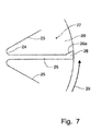
- Fig. 7 is an enlarged detail view of a representative vane on the rotor.
- the rotary valve 10 is operably positionable between a supply hopper 12 providing a supply of particulate material, such as plastic pellets and the like, to be fed into the conduit 15 of a pneumatic conveying system to move the particulate material to a remote location serviced by the pneumatic conveying system.
- the purpose of the rotary valve 10 is to meter the flow of particulate material into the conduit 15 in a manner that the pressurized air within the pneumatic conveying system is retained within the conduit to provide a fluidized flow of the particulate material to the remote location.
- the rotary valve 10 accomplishes this function through the operation of an interior rotor assembly 20 that is formed with radially extending vanes 25 that define chambers or pockets 27 between the vanes 25 to receive the particulate material from the supply hopper 12 and move the particulate material to the conduit 15.
- the housing 16 is formed in a generally cylindrical shape to support the rotational movement of the internal rotor assembly 20, as will be described in greater detail below.
- the housing 16 is formed with a mounting flange 17 at the top of the cylindrically-shaped housing 16 to permit the supply hopper 12 to be coupled thereto so that particulate material will be efficiently fed into the rotary valve 10.
- the housing 16 is also formed with a mounting flange 18 at the bottom of the cylindrically-shaped housing 16 to be coupled to an infeed opening 15a in flow communication with the top of the conduit 15 so that particulate material can flow by gravity from the filled pockets 27 into the pressurized conduit 15 of the pneumatic conveying system.
- the opposing sides of the cylindrically-shaped housing 16 are also formed with mounting flanges 19a that allow the coupling of bearing caps 19 that support respective bearings (not shown) that rotatably support the central shaft 21 of the rotor assembly 20.
- the rotor assembly is best seen in Figs. 2 - 7 and includes a rotor 22 mounted on a central shaft 21, as will be described in greater detail below.
- the instant invention forms the rotor 22 as a precision casting that has a central opening 23 passing therethrough for the insertion of the central shaft 21.
- the shaft 21 is preferably formed of high tension steel to minimize deflection under pressure.
- the rotor 22 is pressed onto the central shaft, and rotatably secured thereto with appropriate keys (not shown) so that the rotor assembly 20 rotates as a single unit.
- the rotor 22 is cast with a central hub 24 defining the central opening 23 for the passage of the shaft 21 from which vanes 25 extend radially.
- the vanes 25 have a uniform length and terminate in a tip 26 that is flared with respect to the radially extending vane 25, as is best seen in Fig. 7 . Because the rotor 22 is formed as a precision casting, the vanes 25 can be kept with a minimal thickness and in various numbers, sufficient to be rigid so as not to deflect during rotation of the rotor 22 or under the pressure of the compressed air within the pockets 27.
- the tips 26, however, can be flared to present an outer surface that is much wider than the nominal thickness of the corresponding vane 25 formed through casting procedures.
- the tips 26 have a thickness that is at least twice the corresponding thickness of the vanes 25.
- the close proximity of the wider tip 26 against the interior surface of the housing 16 restricts the passage of pressurize air around the vane tips 26, at least more so than would be found with a vane tip 26 that is substantially as wide as the nominal thickness of the vane 25.
- the resulting configuration of the rotor 22 provides the air leakage resistance that would be obtained with a conventionally constructed rotor assembly 20 having much thicker and a greater number of vanes 25.
- the rotor casting has attached thereto an end plate 28 that can be separately welded onto the opposing ends of the rotor casting, attaching the vanes thereto, or as part of the precision casting.
- the support of the respective opposing ends of the vanes 25 at the end plates 28 help stabilize the vanes 25 and increase rigidity in the rotor assembly 20.
- the flared tip 26 is preferably constructed such that the increased width of the tip 26, compared to the thickness of the corresponding vane 25, projects only from one side of the vane 25, as is best seen in Figs. 6 and 7 .
- the opposing side of the vane tip 26 is a linear extension of the body of the vane 25.
- the rotor assembly 20 is rotated about the transverse axis of rotation defined by the central shaft 21 in a manner that the straight side of the vane tip 26 is trailing in the rotation of the vane, with the flared side of the tip 26 leading, as is reflected in the directional arrow 29 showing the direction of rotation of the rotor 22 in Figs. 6 and 7 .
- the sloped leading edge 26a of the flared vane tip 26 is less aggressive than a rectangularly-shaped vane tip as the vane tip 26 approaches the edge of the opening of the housing 16 in flow communication with a material supply hopper 12 which helps to prevent damage to the particulate material being metered by the rotary valve 10.
- the rotation of the rotor assembly 20 conveys the particulate material received from the supply hopper 12 when the pocket 27 is rotated to the top position to receive particulate material from the supply hopper 12.
- the pocket 27 is then rotated about the central shaft 21 until the pocket 27 opens into the pneumatic conduit 15 where the particulate material drops by gravity into the conduit 15.
- the higher air pressure present in the pneumatic conduit 15 fills the emptied pocket 27 with air. Further rotation of the pocket back toward the top position to receive another supply of particulate material from the supply hopper 15 traps that quantity of high pressure air in the emptied pocket against the interior surface of the rotor.
- a release port 30 is built into the housing to be in communication with the pockets 27 as they rotate from the bottom position to the top position.
- the release port 30 is preferably coupled to a conduit (not shown) that connects the release port 30 to the supply hopper 12 above the rotary valve 10 to release the air pressure from being trapped in the pocket 27 to being fed into the supply hopper 12 to urge particulate material down into the open pocket 27 at the top position. Without the release port 30 the high pressure air in the pocket 27 would continue around to the top position and release into the supply hopper 12 which would urge the particulate material away from the pocket and limit the flow of particulate material into the pocket 27 to be conveyed into the pneumatic conduit 15.
- the release port 30 preferably extend across substantially the entire width of the pockets 27, as opposed to conventional release ports which is simply a single round port in the middle of the housing 16. As a result, the release port 30 provides a more complete release of the air pressure within the pockets 27 rotating toward the top position and, thus, increases operating efficiency and capacity.
Landscapes
- Engineering & Computer Science (AREA)
- Mechanical Engineering (AREA)
- General Engineering & Computer Science (AREA)
- Filling Or Emptying Of Bunkers, Hoppers, And Tanks (AREA)
Applications Claiming Priority (1)
| Application Number | Priority Date | Filing Date | Title |
|---|---|---|---|
| US16140109P | 2009-03-18 | 2009-03-18 |
Publications (3)
| Publication Number | Publication Date |
|---|---|
| EP2241521A2 EP2241521A2 (en) | 2010-10-20 |
| EP2241521A3 EP2241521A3 (en) | 2011-10-12 |
| EP2241521B1 true EP2241521B1 (en) | 2012-10-03 |
Family
ID=42237008
Family Applications (1)
| Application Number | Title | Priority Date | Filing Date |
|---|---|---|---|
| EP10156567A Not-in-force EP2241521B1 (en) | 2009-03-18 | 2010-03-15 | Rotor configuration for a rotary valve |
Country Status (6)
| Country | Link |
|---|---|
| US (1) | US20100237267A1 (enExample) |
| EP (1) | EP2241521B1 (enExample) |
| JP (1) | JP5666814B2 (enExample) |
| KR (1) | KR20100105468A (enExample) |
| CN (1) | CN101839351A (enExample) |
| TW (1) | TWI383940B (enExample) |
Families Citing this family (19)
| Publication number | Priority date | Publication date | Assignee | Title |
|---|---|---|---|---|
| US8905681B2 (en) * | 2010-07-26 | 2014-12-09 | Pelletron Corporation | Pneumatic conveying process for particulate materials |
| CN102152077A (zh) * | 2011-03-23 | 2011-08-17 | 淮安市胜杰液压机械有限公司 | 液压多路换向阀叠合式阀片微切削加工工艺 |
| US8944295B2 (en) * | 2011-12-12 | 2015-02-03 | Pelletron Corporation | Rotary valve with product relief grooves |
| CN102530496A (zh) * | 2012-01-18 | 2012-07-04 | 金川集团有限公司 | 滚筒下料阀 |
| KR101290073B1 (ko) * | 2013-03-15 | 2013-07-26 | 이춘우 | 로터리밸브 |
| ES2857178T3 (es) * | 2013-03-28 | 2021-09-28 | Nordson Corp | Contenedor de adhesivo y método para almacenar y mover partículas de adhesivo a un fusor de adhesivo |
| CN103803305A (zh) * | 2013-11-05 | 2014-05-21 | 大连四方佳特流体设备有限公司 | 双密封式回转阀 |
| KR101627635B1 (ko) | 2014-06-03 | 2016-06-13 | 주식회사 중정 | 로터리밸브 및 이를 구비한 진공청소기 |
| KR101563535B1 (ko) * | 2014-08-22 | 2015-10-27 | 김상진 | 에어 터빈 바이브레이터 |
| CN105775785B (zh) * | 2016-04-29 | 2019-05-17 | 邢献军 | 一种用于蓬松物料的进料装置 |
| JP2019123575A (ja) * | 2018-01-12 | 2019-07-25 | 株式会社サタケ | ロータリーバルブ及びローター |
| DE102018216654B3 (de) * | 2018-09-27 | 2020-02-13 | Coperion Gmbh | Zellenradschleuse für granulatförmiges Schüttgut |
| CN109372790B (zh) * | 2018-12-20 | 2020-08-18 | 中国航空工业集团公司金城南京机电液压工程研究中心 | 一种集成化泵阀装置 |
| CN109484861A (zh) * | 2018-12-24 | 2019-03-19 | 上海博隆粉体工程有限公司 | 一种粒料旋转阀 |
| CN110985698B (zh) * | 2019-12-20 | 2025-03-07 | 中山市福润德燃气具有限公司 | 燃气控制阀 |
| GB2592012B (en) * | 2020-02-11 | 2022-08-24 | Schenck Process Europe Gmbh | Wear resistant blow-through rotary valve |
| US11555726B2 (en) * | 2020-03-05 | 2023-01-17 | Cnh Industrial Canada, Ltd. | Metering system for distributing particulate material |
| CN111365480B (zh) * | 2020-03-13 | 2022-07-22 | 河南鼎盛铝业有限公司 | 传动机构外置式陶瓷双芯可调缩孔 |
| CN114476721B (zh) * | 2021-12-24 | 2024-02-02 | 齐鲁工业大学 | 一种串联独控式分料器及其应用 |
Family Cites Families (19)
| Publication number | Priority date | Publication date | Assignee | Title |
|---|---|---|---|---|
| US2084764A (en) * | 1935-03-29 | 1937-06-22 | Fuller Co | Conveying bulk materials |
| US2688416A (en) * | 1949-10-21 | 1954-09-07 | Kamyr Ab | Rotary valve |
| DE1013575B (de) * | 1954-09-15 | 1957-08-08 | Edmond Harvengt | Vorrichtung zum Verteilen oder Abgeben von festem, lockerem Gut mittels eines vorzugsweise als Zellentrommel ausgebildeten Trommeldrehschiebers |
| DE1085814B (de) * | 1957-07-26 | 1960-07-21 | Engelsmann Akt Ges J | Zellenradschleuse fuer Anlagen zum Transport von koernigem und pulverigem Gut |
| FR1242592A (fr) * | 1958-12-11 | 1960-08-22 | Defibrator Ab | Chargeur à alvéoles |
| US3130879A (en) * | 1960-08-26 | 1964-04-28 | Black Clawson Co | Rotary feed valve |
| US3085831A (en) * | 1961-10-16 | 1963-04-16 | Allen Sherman Hoff Co | Fine solids transferring device and method |
| US3201007A (en) * | 1962-11-13 | 1965-08-17 | Sherman T Transeau | Rotary feeder mechanism |
| US3399931A (en) * | 1966-07-08 | 1968-09-03 | Clarence W. Vogt | Feed mechanism |
| US3556355A (en) * | 1968-05-28 | 1971-01-19 | Basic Inc | Pressure sealed rotary feeder |
| JPS55156138A (en) * | 1979-05-18 | 1980-12-04 | Furuude Kogyo Kk | Rotary valve coupled directly on motor with reduction gear |
| DE4110036A1 (de) * | 1991-03-27 | 1992-10-01 | Motan Verfahrenstechnik | Zellenradschleuse |
| BR9407456A (pt) * | 1993-08-31 | 1996-11-12 | Stamet Inc | Transporte e medição de material em partículas |
| CN2173768Y (zh) * | 1993-09-01 | 1994-08-10 | 邱瑞东 | 高效气力射流输送泵 |
| US5772081A (en) * | 1996-06-04 | 1998-06-30 | Food Industry Research And Development Institute | Low leakage rotary valve |
| TW458935B (en) * | 1999-07-08 | 2001-10-11 | Nippon Kokan Kk | Method and device for cutting out and transporting powder and granular material |
| DE19960221C2 (de) * | 1999-12-14 | 2002-09-12 | Motan Fuller Verfahrenstechnik | Zellenradschleuse mit verbesserter Abdichtung gegen Leckluft |
| US6471447B1 (en) * | 2001-04-09 | 2002-10-29 | Frank Salley | Rotary air lock feeder with improved material intake and discharge |
| JP4139175B2 (ja) * | 2002-09-20 | 2008-08-27 | 大 岡村 | ロータリーフィーダー |
-
2010
- 2010-03-04 US US12/717,152 patent/US20100237267A1/en not_active Abandoned
- 2010-03-15 TW TW099107487A patent/TWI383940B/zh active
- 2010-03-15 EP EP10156567A patent/EP2241521B1/en not_active Not-in-force
- 2010-03-16 JP JP2010059096A patent/JP5666814B2/ja not_active Expired - Fee Related
- 2010-03-17 KR KR1020100023724A patent/KR20100105468A/ko not_active Ceased
- 2010-03-18 CN CN201010127047A patent/CN101839351A/zh active Pending
Also Published As
| Publication number | Publication date |
|---|---|
| EP2241521A2 (en) | 2010-10-20 |
| EP2241521A3 (en) | 2011-10-12 |
| KR20100105468A (ko) | 2010-09-29 |
| TW201036901A (en) | 2010-10-16 |
| CN101839351A (zh) | 2010-09-22 |
| JP5666814B2 (ja) | 2015-02-12 |
| JP2010228917A (ja) | 2010-10-14 |
| TWI383940B (zh) | 2013-02-01 |
| US20100237267A1 (en) | 2010-09-23 |
Similar Documents
| Publication | Publication Date | Title |
|---|---|---|
| EP2241521B1 (en) | Rotor configuration for a rotary valve | |
| JP2010228917A5 (enExample) | ||
| KR101845572B1 (ko) | 로터리 피스톤 펌프 | |
| GB2478259A (en) | A compressor | |
| US7261513B2 (en) | Centrifugal compressor | |
| EP2672154A2 (en) | Rotary valve with product relief grooves | |
| CN202030327U (zh) | 旋转阀进料口结构 | |
| EA014206B1 (ru) | Прудовой насос | |
| CN107601056B (zh) | 一种并联双转子气力输送给料机 | |
| CN221587248U (zh) | 一种关风机 | |
| EP2678568B1 (en) | Side channel machine arrangement | |
| CN201687724U (zh) | 旋流式渣浆泵 | |
| CN208642941U (zh) | 一种新型回转锁风阀转子机构及一种新型回转锁风阀 | |
| JP3315095B2 (ja) | ロータリーバルブ | |
| CN208642940U (zh) | 一种立磨下料回转锁风阀 | |
| CN208966560U (zh) | 一种用于隔膜泵的板阀以及隔膜泵 | |
| CN222131324U (zh) | 立式活性炭箱 | |
| CN222418339U (zh) | 一种卧式干燥设备 | |
| CN202687499U (zh) | 转轮进料装置 | |
| CN110356850A (zh) | 一种输送泵结构以及粉料输送装置 | |
| JP7498972B2 (ja) | 供給装置 | |
| CN106586571A (zh) | 煤粉输送应用中的可调速给料机 | |
| CN220950184U (zh) | 一种带导流功能旋转卸料阀 | |
| CN209758076U (zh) | 粉体存储桶 | |
| CN201027696Y (zh) | 轴向导流式叶轮 |
Legal Events
| Date | Code | Title | Description |
|---|---|---|---|
| PUAI | Public reference made under article 153(3) epc to a published international application that has entered the european phase |
Free format text: ORIGINAL CODE: 0009012 |
|
| AK | Designated contracting states |
Kind code of ref document: A2 Designated state(s): AT BE BG CH CY CZ DE DK EE ES FI FR GB GR HR HU IE IS IT LI LT LU LV MC MK MT NL NO PL PT RO SE SI SK SM TR |
|
| AX | Request for extension of the european patent |
Extension state: AL BA ME RS |
|
| PUAL | Search report despatched |
Free format text: ORIGINAL CODE: 0009013 |
|
| AK | Designated contracting states |
Kind code of ref document: A3 Designated state(s): AT BE BG CH CY CZ DE DK EE ES FI FR GB GR HR HU IE IS IT LI LT LU LV MC MK MT NL NO PL PT RO SE SI SK SM TR |
|
| AX | Request for extension of the european patent |
Extension state: AL BA ME RS |
|
| RIC1 | Information provided on ipc code assigned before grant |
Ipc: B65G 53/46 20060101AFI20110906BHEP |
|
| 17P | Request for examination filed |
Effective date: 20120412 |
|
| GRAP | Despatch of communication of intention to grant a patent |
Free format text: ORIGINAL CODE: EPIDOSNIGR1 |
|
| GRAS | Grant fee paid |
Free format text: ORIGINAL CODE: EPIDOSNIGR3 |
|
| GRAA | (expected) grant |
Free format text: ORIGINAL CODE: 0009210 |
|
| AK | Designated contracting states |
Kind code of ref document: B1 Designated state(s): AT BE BG CH CY CZ DE DK EE ES FI FR GB GR HR HU IE IS IT LI LT LU LV MC MK MT NL NO PL PT RO SE SI SK SM TR |
|
| REG | Reference to a national code |
Ref country code: GB Ref legal event code: FG4D |
|
| REG | Reference to a national code |
Ref country code: AT Ref legal event code: REF Ref document number: 577878 Country of ref document: AT Kind code of ref document: T Effective date: 20121015 Ref country code: CH Ref legal event code: EP |
|
| REG | Reference to a national code |
Ref country code: IE Ref legal event code: FG4D |
|
| REG | Reference to a national code |
Ref country code: DE Ref legal event code: R096 Ref document number: 602010003020 Country of ref document: DE Effective date: 20121129 |
|
| REG | Reference to a national code |
Ref country code: NL Ref legal event code: T3 |
|
| REG | Reference to a national code |
Ref country code: AT Ref legal event code: MK05 Ref document number: 577878 Country of ref document: AT Kind code of ref document: T Effective date: 20121003 |
|
| PG25 | Lapsed in a contracting state [announced via postgrant information from national office to epo] |
Ref country code: SI Free format text: LAPSE BECAUSE OF FAILURE TO SUBMIT A TRANSLATION OF THE DESCRIPTION OR TO PAY THE FEE WITHIN THE PRESCRIBED TIME-LIMIT Effective date: 20121003 |
|
| REG | Reference to a national code |
Ref country code: LT Ref legal event code: MG4D |
|
| PG25 | Lapsed in a contracting state [announced via postgrant information from national office to epo] |
Ref country code: LT Free format text: LAPSE BECAUSE OF FAILURE TO SUBMIT A TRANSLATION OF THE DESCRIPTION OR TO PAY THE FEE WITHIN THE PRESCRIBED TIME-LIMIT Effective date: 20121003 Ref country code: ES Free format text: LAPSE BECAUSE OF FAILURE TO SUBMIT A TRANSLATION OF THE DESCRIPTION OR TO PAY THE FEE WITHIN THE PRESCRIBED TIME-LIMIT Effective date: 20130114 Ref country code: HR Free format text: LAPSE BECAUSE OF FAILURE TO SUBMIT A TRANSLATION OF THE DESCRIPTION OR TO PAY THE FEE WITHIN THE PRESCRIBED TIME-LIMIT Effective date: 20121003 Ref country code: IS Free format text: LAPSE BECAUSE OF FAILURE TO SUBMIT A TRANSLATION OF THE DESCRIPTION OR TO PAY THE FEE WITHIN THE PRESCRIBED TIME-LIMIT Effective date: 20130203 Ref country code: SE Free format text: LAPSE BECAUSE OF FAILURE TO SUBMIT A TRANSLATION OF THE DESCRIPTION OR TO PAY THE FEE WITHIN THE PRESCRIBED TIME-LIMIT Effective date: 20121003 Ref country code: FI Free format text: LAPSE BECAUSE OF FAILURE TO SUBMIT A TRANSLATION OF THE DESCRIPTION OR TO PAY THE FEE WITHIN THE PRESCRIBED TIME-LIMIT Effective date: 20121003 Ref country code: NO Free format text: LAPSE BECAUSE OF FAILURE TO SUBMIT A TRANSLATION OF THE DESCRIPTION OR TO PAY THE FEE WITHIN THE PRESCRIBED TIME-LIMIT Effective date: 20130103 |
|
| PG25 | Lapsed in a contracting state [announced via postgrant information from national office to epo] |
Ref country code: PT Free format text: LAPSE BECAUSE OF FAILURE TO SUBMIT A TRANSLATION OF THE DESCRIPTION OR TO PAY THE FEE WITHIN THE PRESCRIBED TIME-LIMIT Effective date: 20130204 Ref country code: BE Free format text: LAPSE BECAUSE OF FAILURE TO SUBMIT A TRANSLATION OF THE DESCRIPTION OR TO PAY THE FEE WITHIN THE PRESCRIBED TIME-LIMIT Effective date: 20121003 Ref country code: PL Free format text: LAPSE BECAUSE OF FAILURE TO SUBMIT A TRANSLATION OF THE DESCRIPTION OR TO PAY THE FEE WITHIN THE PRESCRIBED TIME-LIMIT Effective date: 20121003 Ref country code: LV Free format text: LAPSE BECAUSE OF FAILURE TO SUBMIT A TRANSLATION OF THE DESCRIPTION OR TO PAY THE FEE WITHIN THE PRESCRIBED TIME-LIMIT Effective date: 20121003 |
|
| PG25 | Lapsed in a contracting state [announced via postgrant information from national office to epo] |
Ref country code: AT Free format text: LAPSE BECAUSE OF FAILURE TO SUBMIT A TRANSLATION OF THE DESCRIPTION OR TO PAY THE FEE WITHIN THE PRESCRIBED TIME-LIMIT Effective date: 20121003 |
|
| PG25 | Lapsed in a contracting state [announced via postgrant information from national office to epo] |
Ref country code: SK Free format text: LAPSE BECAUSE OF FAILURE TO SUBMIT A TRANSLATION OF THE DESCRIPTION OR TO PAY THE FEE WITHIN THE PRESCRIBED TIME-LIMIT Effective date: 20121003 Ref country code: CZ Free format text: LAPSE BECAUSE OF FAILURE TO SUBMIT A TRANSLATION OF THE DESCRIPTION OR TO PAY THE FEE WITHIN THE PRESCRIBED TIME-LIMIT Effective date: 20121003 Ref country code: DK Free format text: LAPSE BECAUSE OF FAILURE TO SUBMIT A TRANSLATION OF THE DESCRIPTION OR TO PAY THE FEE WITHIN THE PRESCRIBED TIME-LIMIT Effective date: 20121003 Ref country code: BG Free format text: LAPSE BECAUSE OF FAILURE TO SUBMIT A TRANSLATION OF THE DESCRIPTION OR TO PAY THE FEE WITHIN THE PRESCRIBED TIME-LIMIT Effective date: 20130103 Ref country code: EE Free format text: LAPSE BECAUSE OF FAILURE TO SUBMIT A TRANSLATION OF THE DESCRIPTION OR TO PAY THE FEE WITHIN THE PRESCRIBED TIME-LIMIT Effective date: 20121003 |
|
| PLBE | No opposition filed within time limit |
Free format text: ORIGINAL CODE: 0009261 |
|
| STAA | Information on the status of an ep patent application or granted ep patent |
Free format text: STATUS: NO OPPOSITION FILED WITHIN TIME LIMIT |
|
| PG25 | Lapsed in a contracting state [announced via postgrant information from national office to epo] |
Ref country code: RO Free format text: LAPSE BECAUSE OF FAILURE TO SUBMIT A TRANSLATION OF THE DESCRIPTION OR TO PAY THE FEE WITHIN THE PRESCRIBED TIME-LIMIT Effective date: 20121003 |
|
| 26N | No opposition filed |
Effective date: 20130704 |
|
| PG25 | Lapsed in a contracting state [announced via postgrant information from national office to epo] |
Ref country code: MC Free format text: LAPSE BECAUSE OF NON-PAYMENT OF DUE FEES Effective date: 20130331 |
|
| REG | Reference to a national code |
Ref country code: DE Ref legal event code: R097 Ref document number: 602010003020 Country of ref document: DE Effective date: 20130704 |
|
| PG25 | Lapsed in a contracting state [announced via postgrant information from national office to epo] |
Ref country code: CY Free format text: LAPSE BECAUSE OF FAILURE TO SUBMIT A TRANSLATION OF THE DESCRIPTION OR TO PAY THE FEE WITHIN THE PRESCRIBED TIME-LIMIT Effective date: 20121003 |
|
| REG | Reference to a national code |
Ref country code: IE Ref legal event code: MM4A |
|
| PG25 | Lapsed in a contracting state [announced via postgrant information from national office to epo] |
Ref country code: IE Free format text: LAPSE BECAUSE OF NON-PAYMENT OF DUE FEES Effective date: 20130315 |
|
| PG25 | Lapsed in a contracting state [announced via postgrant information from national office to epo] |
Ref country code: MT Free format text: LAPSE BECAUSE OF FAILURE TO SUBMIT A TRANSLATION OF THE DESCRIPTION OR TO PAY THE FEE WITHIN THE PRESCRIBED TIME-LIMIT Effective date: 20121003 |
|
| REG | Reference to a national code |
Ref country code: CH Ref legal event code: PL |
|
| PG25 | Lapsed in a contracting state [announced via postgrant information from national office to epo] |
Ref country code: CH Free format text: LAPSE BECAUSE OF NON-PAYMENT OF DUE FEES Effective date: 20140331 Ref country code: LI Free format text: LAPSE BECAUSE OF NON-PAYMENT OF DUE FEES Effective date: 20140331 |
|
| PG25 | Lapsed in a contracting state [announced via postgrant information from national office to epo] |
Ref country code: SM Free format text: LAPSE BECAUSE OF FAILURE TO SUBMIT A TRANSLATION OF THE DESCRIPTION OR TO PAY THE FEE WITHIN THE PRESCRIBED TIME-LIMIT Effective date: 20121003 |
|
| PG25 | Lapsed in a contracting state [announced via postgrant information from national office to epo] |
Ref country code: TR Free format text: LAPSE BECAUSE OF FAILURE TO SUBMIT A TRANSLATION OF THE DESCRIPTION OR TO PAY THE FEE WITHIN THE PRESCRIBED TIME-LIMIT Effective date: 20121003 |
|
| PG25 | Lapsed in a contracting state [announced via postgrant information from national office to epo] |
Ref country code: HU Free format text: LAPSE BECAUSE OF FAILURE TO SUBMIT A TRANSLATION OF THE DESCRIPTION OR TO PAY THE FEE WITHIN THE PRESCRIBED TIME-LIMIT; INVALID AB INITIO Effective date: 20100315 Ref country code: LU Free format text: LAPSE BECAUSE OF NON-PAYMENT OF DUE FEES Effective date: 20130315 Ref country code: MK Free format text: LAPSE BECAUSE OF FAILURE TO SUBMIT A TRANSLATION OF THE DESCRIPTION OR TO PAY THE FEE WITHIN THE PRESCRIBED TIME-LIMIT Effective date: 20121003 |
|
| PG25 | Lapsed in a contracting state [announced via postgrant information from national office to epo] |
Ref country code: GR Free format text: LAPSE BECAUSE OF NON-PAYMENT OF DUE FEES Effective date: 20121003 |
|
| REG | Reference to a national code |
Ref country code: FR Ref legal event code: PLFP Year of fee payment: 7 |
|
| REG | Reference to a national code |
Ref country code: FR Ref legal event code: PLFP Year of fee payment: 8 |
|
| REG | Reference to a national code |
Ref country code: FR Ref legal event code: PLFP Year of fee payment: 9 |
|
| PGFP | Annual fee paid to national office [announced via postgrant information from national office to epo] |
Ref country code: GB Payment date: 20200218 Year of fee payment: 11 Ref country code: NL Payment date: 20200311 Year of fee payment: 11 Ref country code: DE Payment date: 20200319 Year of fee payment: 11 Ref country code: IT Payment date: 20200320 Year of fee payment: 11 |
|
| PGFP | Annual fee paid to national office [announced via postgrant information from national office to epo] |
Ref country code: FR Payment date: 20200310 Year of fee payment: 11 |
|
| REG | Reference to a national code |
Ref country code: DE Ref legal event code: R119 Ref document number: 602010003020 Country of ref document: DE |
|
| REG | Reference to a national code |
Ref country code: NL Ref legal event code: MM Effective date: 20210401 |
|
| GBPC | Gb: european patent ceased through non-payment of renewal fee |
Effective date: 20210315 |
|
| PG25 | Lapsed in a contracting state [announced via postgrant information from national office to epo] |
Ref country code: DE Free format text: LAPSE BECAUSE OF NON-PAYMENT OF DUE FEES Effective date: 20211001 Ref country code: FR Free format text: LAPSE BECAUSE OF NON-PAYMENT OF DUE FEES Effective date: 20210331 Ref country code: GB Free format text: LAPSE BECAUSE OF NON-PAYMENT OF DUE FEES Effective date: 20210315 Ref country code: NL Free format text: LAPSE BECAUSE OF NON-PAYMENT OF DUE FEES Effective date: 20210401 |
|
| PG25 | Lapsed in a contracting state [announced via postgrant information from national office to epo] |
Ref country code: IT Free format text: LAPSE BECAUSE OF NON-PAYMENT OF DUE FEES Effective date: 20210315 |