EP2241498B1 - Régulateur de vitesse pour une motocyclette - Google Patents
Régulateur de vitesse pour une motocyclette Download PDFInfo
- Publication number
- EP2241498B1 EP2241498B1 EP10159820.9A EP10159820A EP2241498B1 EP 2241498 B1 EP2241498 B1 EP 2241498B1 EP 10159820 A EP10159820 A EP 10159820A EP 2241498 B1 EP2241498 B1 EP 2241498B1
- Authority
- EP
- European Patent Office
- Prior art keywords
- accelerator
- grip
- accelerator grip
- fully closed
- control device
- Prior art date
- Legal status (The legal status is an assumption and is not a legal conclusion. Google has not performed a legal analysis and makes no representation as to the accuracy of the status listed.)
- Active
Links
Images


Classifications
-
- B—PERFORMING OPERATIONS; TRANSPORTING
- B62—LAND VEHICLES FOR TRAVELLING OTHERWISE THAN ON RAILS
- B62K—CYCLES; CYCLE FRAMES; CYCLE STEERING DEVICES; RIDER-OPERATED TERMINAL CONTROLS SPECIALLY ADAPTED FOR CYCLES; CYCLE AXLE SUSPENSIONS; CYCLE SIDE-CARS, FORECARS, OR THE LIKE
- B62K23/00—Rider-operated controls specially adapted for cycles, i.e. means for initiating control operations, e.g. levers, grips
- B62K23/02—Rider-operated controls specially adapted for cycles, i.e. means for initiating control operations, e.g. levers, grips hand actuated
- B62K23/04—Twist grips
-
- B—PERFORMING OPERATIONS; TRANSPORTING
- B60—VEHICLES IN GENERAL
- B60K—ARRANGEMENT OR MOUNTING OF PROPULSION UNITS OR OF TRANSMISSIONS IN VEHICLES; ARRANGEMENT OR MOUNTING OF PLURAL DIVERSE PRIME-MOVERS IN VEHICLES; AUXILIARY DRIVES FOR VEHICLES; INSTRUMENTATION OR DASHBOARDS FOR VEHICLES; ARRANGEMENTS IN CONNECTION WITH COOLING, AIR INTAKE, GAS EXHAUST OR FUEL SUPPLY OF PROPULSION UNITS IN VEHICLES
- B60K26/00—Arrangements or mounting of propulsion unit control devices in vehicles
- B60K26/02—Arrangements or mounting of propulsion unit control devices in vehicles of initiating means or elements
- B60K26/021—Arrangements or mounting of propulsion unit control devices in vehicles of initiating means or elements with means for providing feel, e.g. by changing pedal force characteristics
-
- B—PERFORMING OPERATIONS; TRANSPORTING
- B60—VEHICLES IN GENERAL
- B60K—ARRANGEMENT OR MOUNTING OF PROPULSION UNITS OR OF TRANSMISSIONS IN VEHICLES; ARRANGEMENT OR MOUNTING OF PLURAL DIVERSE PRIME-MOVERS IN VEHICLES; AUXILIARY DRIVES FOR VEHICLES; INSTRUMENTATION OR DASHBOARDS FOR VEHICLES; ARRANGEMENTS IN CONNECTION WITH COOLING, AIR INTAKE, GAS EXHAUST OR FUEL SUPPLY OF PROPULSION UNITS IN VEHICLES
- B60K31/00—Vehicle fittings, acting on a single sub-unit only, for automatically controlling vehicle speed, i.e. preventing speed from exceeding an arbitrarily established velocity or maintaining speed at a particular velocity, as selected by the vehicle operator
- B60K31/02—Vehicle fittings, acting on a single sub-unit only, for automatically controlling vehicle speed, i.e. preventing speed from exceeding an arbitrarily established velocity or maintaining speed at a particular velocity, as selected by the vehicle operator including electrically actuated servomechanism including an electric control system or a servomechanism in which the vehicle velocity affecting element is actuated electrically
- B60K31/04—Vehicle fittings, acting on a single sub-unit only, for automatically controlling vehicle speed, i.e. preventing speed from exceeding an arbitrarily established velocity or maintaining speed at a particular velocity, as selected by the vehicle operator including electrically actuated servomechanism including an electric control system or a servomechanism in which the vehicle velocity affecting element is actuated electrically and means for comparing one electrical quantity, e.g. voltage, pulse, waveform, flux, or the like, with another quantity of a like kind, which comparison means is involved in the development of an electrical signal which is fed into the controlling means
- B60K31/042—Vehicle fittings, acting on a single sub-unit only, for automatically controlling vehicle speed, i.e. preventing speed from exceeding an arbitrarily established velocity or maintaining speed at a particular velocity, as selected by the vehicle operator including electrically actuated servomechanism including an electric control system or a servomechanism in which the vehicle velocity affecting element is actuated electrically and means for comparing one electrical quantity, e.g. voltage, pulse, waveform, flux, or the like, with another quantity of a like kind, which comparison means is involved in the development of an electrical signal which is fed into the controlling means where at least one electrical quantity is set by the vehicle operator
- B60K31/045—Vehicle fittings, acting on a single sub-unit only, for automatically controlling vehicle speed, i.e. preventing speed from exceeding an arbitrarily established velocity or maintaining speed at a particular velocity, as selected by the vehicle operator including electrically actuated servomechanism including an electric control system or a servomechanism in which the vehicle velocity affecting element is actuated electrically and means for comparing one electrical quantity, e.g. voltage, pulse, waveform, flux, or the like, with another quantity of a like kind, which comparison means is involved in the development of an electrical signal which is fed into the controlling means where at least one electrical quantity is set by the vehicle operator in a memory, e.g. a capacitor
- B60K31/047—Vehicle fittings, acting on a single sub-unit only, for automatically controlling vehicle speed, i.e. preventing speed from exceeding an arbitrarily established velocity or maintaining speed at a particular velocity, as selected by the vehicle operator including electrically actuated servomechanism including an electric control system or a servomechanism in which the vehicle velocity affecting element is actuated electrically and means for comparing one electrical quantity, e.g. voltage, pulse, waveform, flux, or the like, with another quantity of a like kind, which comparison means is involved in the development of an electrical signal which is fed into the controlling means where at least one electrical quantity is set by the vehicle operator in a memory, e.g. a capacitor the memory being digital
-
- F—MECHANICAL ENGINEERING; LIGHTING; HEATING; WEAPONS; BLASTING
- F02—COMBUSTION ENGINES; HOT-GAS OR COMBUSTION-PRODUCT ENGINE PLANTS
- F02D—CONTROLLING COMBUSTION ENGINES
- F02D11/00—Arrangements for, or adaptations to, non-automatic engine control initiation means, e.g. operator initiated
- F02D11/02—Arrangements for, or adaptations to, non-automatic engine control initiation means, e.g. operator initiated characterised by hand, foot, or like operator controlled initiation means
-
- F—MECHANICAL ENGINEERING; LIGHTING; HEATING; WEAPONS; BLASTING
- F02—COMBUSTION ENGINES; HOT-GAS OR COMBUSTION-PRODUCT ENGINE PLANTS
- F02D—CONTROLLING COMBUSTION ENGINES
- F02D41/00—Electrical control of supply of combustible mixture or its constituents
- F02D41/24—Electrical control of supply of combustible mixture or its constituents characterised by the use of digital means
- F02D41/2406—Electrical control of supply of combustible mixture or its constituents characterised by the use of digital means using essentially read only memories
- F02D41/2425—Particular ways of programming the data
- F02D41/2429—Methods of calibrating or learning
- F02D41/2451—Methods of calibrating or learning characterised by what is learned or calibrated
- F02D41/2464—Characteristics of actuators
-
- B—PERFORMING OPERATIONS; TRANSPORTING
- B60—VEHICLES IN GENERAL
- B60Y—INDEXING SCHEME RELATING TO ASPECTS CROSS-CUTTING VEHICLE TECHNOLOGY
- B60Y2200/00—Type of vehicle
- B60Y2200/10—Road Vehicles
- B60Y2200/12—Motorcycles, Trikes; Quads; Scooters
-
- F—MECHANICAL ENGINEERING; LIGHTING; HEATING; WEAPONS; BLASTING
- F02—COMBUSTION ENGINES; HOT-GAS OR COMBUSTION-PRODUCT ENGINE PLANTS
- F02B—INTERNAL-COMBUSTION PISTON ENGINES; COMBUSTION ENGINES IN GENERAL
- F02B61/00—Adaptations of engines for driving vehicles or for driving propellers; Combinations of engines with gearing
- F02B61/02—Adaptations of engines for driving vehicles or for driving propellers; Combinations of engines with gearing for driving cycles
-
- F—MECHANICAL ENGINEERING; LIGHTING; HEATING; WEAPONS; BLASTING
- F02—COMBUSTION ENGINES; HOT-GAS OR COMBUSTION-PRODUCT ENGINE PLANTS
- F02D—CONTROLLING COMBUSTION ENGINES
- F02D11/00—Arrangements for, or adaptations to, non-automatic engine control initiation means, e.g. operator initiated
- F02D11/06—Arrangements for, or adaptations to, non-automatic engine control initiation means, e.g. operator initiated characterised by non-mechanical control linkages, e.g. fluid control linkages or by control linkages with power drive or assistance
- F02D11/10—Arrangements for, or adaptations to, non-automatic engine control initiation means, e.g. operator initiated characterised by non-mechanical control linkages, e.g. fluid control linkages or by control linkages with power drive or assistance of the electric type
- F02D2011/101—Arrangements for, or adaptations to, non-automatic engine control initiation means, e.g. operator initiated characterised by non-mechanical control linkages, e.g. fluid control linkages or by control linkages with power drive or assistance of the electric type characterised by the means for actuating the throttles
- F02D2011/102—Arrangements for, or adaptations to, non-automatic engine control initiation means, e.g. operator initiated characterised by non-mechanical control linkages, e.g. fluid control linkages or by control linkages with power drive or assistance of the electric type characterised by the means for actuating the throttles at least one throttle being moved only by an electric actuator
-
- F—MECHANICAL ENGINEERING; LIGHTING; HEATING; WEAPONS; BLASTING
- F02—COMBUSTION ENGINES; HOT-GAS OR COMBUSTION-PRODUCT ENGINE PLANTS
- F02D—CONTROLLING COMBUSTION ENGINES
- F02D2200/00—Input parameters for engine control
- F02D2200/60—Input parameters for engine control said parameters being related to the driver demands or status
- F02D2200/602—Pedal position
-
- Y—GENERAL TAGGING OF NEW TECHNOLOGICAL DEVELOPMENTS; GENERAL TAGGING OF CROSS-SECTIONAL TECHNOLOGIES SPANNING OVER SEVERAL SECTIONS OF THE IPC; TECHNICAL SUBJECTS COVERED BY FORMER USPC CROSS-REFERENCE ART COLLECTIONS [XRACs] AND DIGESTS
- Y10—TECHNICAL SUBJECTS COVERED BY FORMER USPC
- Y10T—TECHNICAL SUBJECTS COVERED BY FORMER US CLASSIFICATION
- Y10T74/00—Machine element or mechanism
- Y10T74/20—Control lever and linkage systems
- Y10T74/20396—Hand operated
- Y10T74/20474—Rotatable rod, shaft, or post
Definitions
- the present invention relates to a cruise control device for a motorcycle according to the preamble of claim 1.
- a constant speed running control device for a motorcycle that automatically releases constant speed running control when a rider rotates an accelerator grip during the constant speed running control in addition to a brake operation and a clutch operation (for example, see Patent Document 2 (Japanese Patent Laid-Open No. 2001-246960 )).
- the conventional constant speed running control device fixes a position of a throttle pulley around which the throttle cable is wound or the throttle cable itself to maintain the opening degree of the throttle valve and performs cruise control when a predetermined switch such as a cruising vehicle speed set switch is operated while a motorcycle is running at a speed predetermined by a rider.
- a predetermined switch such as a cruising vehicle speed set switch
- the accelerator grip connected to the throttle valve via the throttle cable is also fixed in a position corresponding to the opening degree of the throttle valve.
- a drive-by-wire electronic throttle control system does not include a throttle cable connecting the accelerator grip to the throttle valve.
- the accelerator grip during cruise control is not fixed in a position corresponding to the opening degree of the throttle valve, but is generally placed in a fully closed position.
- US 2007/084658 A1 discloses a control device having a structure in which when a throttle grip is operated into the closing direction over the fully closed position, an arm portion presses a pressing piece which in turn presses a detector shaft, thereby changing a switching mode of a cancel switch. Thereby, an automatic cruising state is released.
- EP 2 011 728 A1 discloses a throttle device for a vehicle having a contact-free magnetic sensor for detecting the turning amount of a throttle grip.
- the present invention provides a cruise control device for a motorcycle having the features of claim 1.
- a cruise control device for a motorcycle that configures an accelerator grip that can be excessively rotated in a further closing direction from a general fully closed position, and can detect excessive rotation of the accelerator grip to automatically release cruise control.
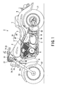
- Fig. 1 is a left side view showing a motorcycle using a vehicle control device according to the embodiment of present invention.
- a motorcycle 1 (vehicle) includes a vehicle body frame 2 mainly formed of a steel pipe into a double cradle shape.
- a front and rear two cylinder V-type engine 3 is mounted in a front half portion (double cradle portion) of the vehicle body frame 2, and a fuel tank 4 is placed in an upper portion of the vehicle body frame 2 so as to be located on the V-type engine 3.
- a seat 5 and a rear fender 6 are placed in order behind the fuel tank 4, and a pillion passenger seat 7 is provided on the rear fender 6.
- Pair of left and right steps 8 are provided near a lower front portion of the vehicle body frame 2, and a radiator 9 is provided on a front surface of the vehicle body frame 2.
- a header pipe 10 is provided in a front head of the vehicle body frame 2.
- a pair of front fork 13 that supports a front wheel 12 via a steering head 11 is laterally rotatably journaled on the header pipe 10 together with a handlebar 14 and a front fender 15.
- a swing pivot shaft 16 is provided in a vehicle width direction in a lower middle portion of the vehicle body frame 2.
- a rear swing arm 18 that supports a rear wheel 17 is vertically rotatably journaled by the swing pivot shaft 16 in a rear half portion of the vehicle body frame 2.
- a rear wheel suspension system (not shown) is provided near a base of the rear swing arm 18.
- a shaft drive type secondary deceleration mechanism of the motorcycle 1 is used, and an output of the V-type engine 3 is transmitted via a transmission 19 to the rear wheel 17 by a drive shaft (not shown), for example, inserted in the rear swing arm 18.
- the motorcycle 1 includes a vehicle control device 21.
- the vehicle control device 21 includes an accelerator position sensor 24 that detects an operation amount of an accelerator grip 23 of the handlebar 14, a throttle valve 25 opened and closed according to an output value of the accelerator position sensor 24, and an electric control unit 26 that drives to open and close the throttle valve 25 based on the output value of the accelerator position sensor 24.
- the accelerator position sensor 24 is placed in a portion surrounded by an upper bracket 27 and an under bracket 28 of the steering head 11 and the pair of front forks 13.
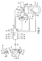
- Fig. 2 is a schematic view showing the vehicle control device according to the embodiment of present invention and the engine.
- the engine 3 includes a cylinder block 30, a cylinder head 31, a piston 32, a crankshaft 34, a connecting rod 35, a combustion chamber 36, an intake pipe 37, an intake valve 38, an exhaust pipe 40, an exhaust valve 41, an ignition plug 42, an engine RPM(Rotation Per Minute) sensor 44, and a throttle body 48.
- the cylinder head 31 is secured to the cylinder block 30.
- the piston 32 is reciprocatably housed in the cylinder block 30.
- the crankshaft 34 is rotatably housed in the cylinder block 30.
- One end of the connecting rod 35 is swingably connected to the crankshaft 34, and the other end thereof is swingably connected to the piston 32.
- the connecting rod 35 converts reciprocating motion of the piston 32 into rotary motion of the crankshaft 34.
- the combustion chamber 36 is formed as a compartment between the piston 32 and the cylinder head 31.
- the intake pipe 37 and the exhaust pipe 40 each communicate with the combustion chamber 36.
- the intake valve 38 is provided in the cylinder head 31, and opens and closes an intake port 37a of the intake pipe 37.
- the ignition plug 42 is provided in the combustion chamber 36.
- the engine RPM sensor 44 detects an RPM of the engine 3 from an RPM of the crankshaft 34.
- the throttle body 48 is provided in the intake pipe 37.
- the throttle valve 25 is provided in the throttle body 48.
- the throttle valve 25 is opened and closed by the vehicle control device 21 according to an opening degree of the accelerator grip 23 provided on the handlebar 14.
- an injector 51 as a fuel injection device is provided.
- the injector 51 is connected to a strainer (not shown) provided in the fuel tank 4, a fuel pump (not shown), and a pressure control valve (pressure regulator, not shown).
- the engine 3 is, for example, of an independent intake type, and the injector 51 is provided for each cylinder.
- the vehicle control device 21 drives to open and close the throttle valve 25 according to the operation amount of the accelerator grip 23 (accelerator opening degree) and performs cruise control, and causes the motorcycle 1 to run at a speed predetermined by the rider.
- the vehicle control device 21 includes the accelerator grip 23, an accelerator return spring 54 (biasing unit), an accelerator grip excessive rotation mechanism unit 55 (restricting unit), an accelerator position sensor 56, an electric motor 57, the throttle valve 25, a throttle position sensor 58, a front brake switch 59, a rear brake switch 60, a clutch switch 61, a speed sensor 63, a cruise control standby switch 64, a cruising vehicle speed setting switch 66, a memory vehicle speed calling switch 67, and the electric control unit 26 (control unit).
- the accelerator grip 23 is rotatably provided on the handlebar 14 in a predetermined first angle range ⁇ 1.
- the accelerator grip 23 is placed in a position corresponding to a fully closed state of the throttle valve 25 at one circumferential end a in a predetermined second angle range ⁇ 2 smaller than the predetermined first angle range ⁇ 1, and in a position corresponding to a fully opened state of the throttle valve 25 at the other circumferential end b.
- the second angle range ⁇ 2 corresponds to the accelerator opening degree of the accelerator grip 23.
- An angle formed by one circumferential end c in the predetermined first angle range ⁇ 1 and one circumferential end a in the predetermined second angle range ⁇ 2 is an excessive rotation range ⁇ , and a phase angle of the other circumferential end d in the predetermined first angle range ⁇ 1 matches a phase angle of the other circumferential end b in the predetermined second angle range ⁇ 2.
- the accelerator return spring 54 rotationally biases the accelerator grip 23 to rotate in one circumferential direction, and returns the accelerator grip 23 to which an operational force is not input to the position corresponding to the fully closed state of the throttle valve 25.
- the accelerator grip excessive rotation mechanism unit 55 restricts rotation of the accelerator grip 23 against the accelerator return spring 54, and places the accelerator grip 23 at a predetermined opening degree, for example, at one circumferential end a in the predetermined second angle range ⁇ 2, specifically, the position corresponding to the fully closed state of the throttle valve 25.
- the accelerator grip excessive rotation mechanism unit 55 releases restriction of the accelerator grip 23 when the rider of the motorcycle 1 applies, to the accelerator grip 23, a predetermined excessive rotation operational force F or more (a predetermined operational force or more) in one circumferential direction, that is, in a closing operation over predetermined opening degree thereof, and causes the accelerator grip 23 to enter the excessive rotation range ⁇ beyond the predetermined opening degree.
- the accelerator grip excessive rotation mechanism unit 55 includes a protrusion 72 formed on an accelerator pulley 71, an accelerator pulley stopper 73 (stopper member), a stopper support spring 74 (stopper biasing member), and a fully closed adjustment screw 75 (opening degree adjustment member).
- the accelerator pulley 71 is interlocked with the accelerator grip 23 via an accelerator wire 76.
- a rotation operation of the accelerator grip 23 causes the protrusion 72 to move with the accelerator pulley 71, and abut against the accelerator pulley stopper 73 when the accelerator grip 23 is placed in the fully closed position.
- the accelerator pulley stopper 73 is a stopper in the fully closed position of the accelerator pulley 71, and swingably journaled on a support shaft 77.
- the stopper support spring 74 applies a rotation biasing force in a direction opposite to a direction of the biasing force of the accelerator return spring 54, that is, in an opening direction via the accelerator pulley stopper 73 to the accelerator pulley 71.
- the stopper support spring 74 biases the accelerator pulley 71 with a larger biasing force than the accelerator return spring 54.
- the stopper support spring 74 is swung by the protrusion 72 and causes the accelerator grip 23 to enter the excessive rotation range ⁇ when the rider of the motorcycle 1 applies a predetermined excessive rotation operational force F or more in one circumferential direction, that is, in the closing direction is applied to the accelerator grip 23.
- the fully closed adjustment screw 75 can adjust a swing amount of the accelerator pulley stopper 73 biased by the stopper support spring 74, and restrict a swing position of the accelerator pulley stopper 73 to adjust the fully closed position of the accelerator grip 23.
- the protrusion 72 on the accelerator pulley 71, the accelerator pulley stopper 73, and the fully closed adjustment screw 75 are all made of a conductive material.
- conductive states of the protrusion 72 on the accelerator pulley 71, the accelerator pulley stopper 73, and the fully closed adjustment screw 75 are detected by the electric control unit 26.
- the accelerator position sensor 56 detects an operation amount (accelerator opening degree) of the accelerator grip 23 via the accelerator pulley 71, and outputs the operation amount to the electric control unit 26.
- the accelerator position sensor 56 detects excessive rotation of the accelerator grip 23 via the accelerator pulley 71, and outputs an excessive rotation signal to the electric control unit 26.
- the electric motor 57 is driven by the electric control unit 26 corresponding to the operation amount of the accelerator grip 23 detected by the accelerator position sensor 56.
- the throttle valve 25 is driven to be opened and closed by the electric motor 57.
- the throttle position sensor 58 detects a throttle opening degree (actual opening degree) of the throttle valve 25 and outputs the opening degree to the electric control unit 26.
- the front brake switch 59 detects ON/OFF of a brake operation of a front brake (not shown) and outputs the ON/OFF to the electric control unit 26.
- the rear brake switch 60 detects ON/OFF of a brake operation of a rear brake (not shown) and outputs the ON/OFF to the electric control unit 26.
- the clutch switch 61 detects ON/OFF of an operation of a clutch (not shown) and outputs the ON/OFF to the electric control unit 26.
- the speed sensor 63 detects a vehicle speed of the motorcycle 1 and outputs the vehicle speed to the electric control unit 26.
- the cruise control standby switch 64 outputs a standby signal for shifting to a state where the cruise control can be started to the electric control unit 26.
- the cruising vehicle speed setting switch 66 outputs a cruising vehicle speed control start signal for starting the cruise control at the vehicle speed detected by the vehicle speed sensor 63 to the electric control unit 26.
- the memory vehicle speed calling switch 67 outputs a memory vehicle speed calling control start signal for starting the cruise control at a vehicle speed when the previous cruise control is performed to the electric control unit 26.
- the electric control unit 26 controls an operation state of the engine 3. Operation control of the engine 3 by the electric control unit 26 includes normal running control that controls the opening degree of the throttle valve 25 according to the rotation operation of the accelerator grip 23, and the cruise control. The electric control unit 26 controls to drive the electric motor 57 based on output values of the accelerator position sensor 56 and the throttle position sensor 58, and controls the operation state of the engine 3.
- the electric control unit 26 receives detection results, as control inputs, from the accelerator position sensor 56, the throttle position sensor 58, the engine RPM sensor 44, the front brake switch 59, the rear brake switch 60, the clutch switch 61, the speed sensor 63, the cruise control standby switch 64, the cruising vehicle speed setting switch 66, and the memory vehicle speed calling switch 67.
- the electric control unit 26 can also receive a detection result from a pressure sensor (not shown) that detects pressure in the intake pipe 37.
- the electric control unit 26 outputs control signals to a fuel pump, the injector 51, the ignition plug 42, and the electric motor 57 based on the control inputs.
- the electric control unit 26 is, for example, constituted by a microcomputer (not shown), and includes a storage unit 79.
- the electric control unit 26 calculates a target opening degree of the throttle valve 25 from an accelerator opening degree detected by the accelerator position sensor 56 and performs feedforward control (hereinafter simply referred to as FF control) of the engine 3.
- the target opening degree of the throttle valve 25 is a throttle opening degree to be reached by the throttle valve 25 according to the accelerator opening degree detected by the accelerator position sensor 56, and calculated, for example, by multiplying the accelerator opening degree by a predetermined coefficient, but may be calculated using an arithmetic expression other than multiplication or a predetermined two-dimensional table.
- the FF control searches a feedforward map preset according to the target opening degree of the throttle valve 25 and the engine RPM, and determines a target duty value of the electric motor 57 at which the target opening degree can be held.
- the feedforward map is a so-called three-dimensional map including the RPM of the engine 3, the target opening degree of the throttle valve 25, and the target duty value of the electric motor 57 at which the target opening degree can be held.
- the electric control unit 26 further performs feedback control (hereinafter simply referred to as FB control) that converges the throttle opening degree of the throttle valve 25 to the target opening degree according to a deviation between the target opening degree (target value) of the throttle valve 25 calculated by the FF control and the throttle opening degree (control value) of the throttle valve 25 detected by the throttle position sensor 58.
- FB control feedback control
- the electric control unit 26 shifts to the state where the cruise control can be started. Then, when the electric control unit 26 receives the cruising vehicle speed control start signal by the rider operating the cruising vehicle speed setting switch 66, the electric control unit 26 stores a vehicle speed detected by a vehicle speed sensor 78 at that time in the storage unit 79, opens and closes the throttle opening degree of the throttle valve 25, and controls the motorcycle 1 to a constant speed running state at the vehicle speed stored in the storage unit 79.
- the electric control unit 26 When the electric control unit 26 receives a memory vehicle speed calling control start signal by the rider operating the cruise control standby switch 64 and then operating the memory vehicle speed calling switch 67, the electric control unit 26 reads the vehicle speed in the previous cruise control stored in the storage unit 79, opens and closes the throttle opening degree of the throttle valve 25, and controls the motorcycle 1 to the constant speed running state at the vehicle speed stored in the storage unit 79.
- the electric control unit 26 performs the cruise control, the motorcycle 1 runs at a constant speed irrespective of the accelerator opening degree detected by the accelerator position sensor 56. The rider does not need to operate the accelerator grip 23 during the cruise control, and can return the accelerator grip 23 to the fully closed position.
- the electric control unit 26 when the electric control unit 26 receives a signal from any of the front brake switch 59, the rear brake switch 60, and the clutch switch 61 after the control in the constant speed running state is started, the electric control unit 26 automatically releases the cruise control and returns to the normal running control state.
- Figs. 3 and 4 are views showing the accelerator grip excessive rotation mechanism unit of the vehicle control device according to the embodiment of present invention.
- Fig. 3 is a view showing a state where the accelerator grip is placed in the fully closed position
- Fig. 4 is a view showing a state where the accelerator grip is excessively rotated.
- the accelerator grip excessive rotation mechanism unit 55 of the vehicle control device 21 when a predetermined excessive rotation operational force F or more by the rider causes the accelerator grip 23 to enter the excessive rotation range ⁇ , the accelerator pulley 71 is also excessively rotated. Thus, the protrusion 72 abuts against the accelerator pulley stopper 73 and swings the accelerator pulley stopper 73 away from the fully closed adjustment screw 75.
- the electric control unit 26 When the electric control unit 26 receives the excessive rotation signal from the accelerator position sensor 56 after the control in the constant speed running state is started and then the cruise control is started, the electric control unit 26 automatically releases the cruise control and returns to the normal running control state.
- the electric control unit 26 detects nonconductive states of the protrusion 72 on the accelerator pulley 71, the accelerator pulley stopper 73, and the fully closed adjustment screw 75.
- Fig. 5 is a flowchart showing fully closed learning control of the vehicle control device according to the embodiment of present invention.
- the accelerator grip 23 is placed in the fully closed position in a natural state without the rotation operation by the rider, and excessively rotated according to the predetermined excessive rotation operational force F or more by the rider. Then, the electric control unit 26 performs learning control in the fully closed position of the accelerator grip 23 to associate the fully closed position of the accelerator grip 23 with the output signal of the accelerator position sensor 56 for calibration.
- the electric control unit 26 of the vehicle control device 21 stores, in the storage unit 79 of the electric control unit 26, the output value of the accelerator position sensor 56 when the accelerator pulley stopper 73 is in contact with the protrusion 72 on the accelerator pulley 71 and the fully closed adjustment screw 75 as the fully closed position of the accelerator grip 23 during cranking operation of the motorcycle 1.
- both the protrusion 72 and the fully closed adjustment screw 75 abut against the accelerator pulley stopper 73 when the accelerator grip 23 is placed in the fully closed position, the conductive states or the nonconductive states thereof are checked to determine whether the accelerator grip 23 is placed in the fully closed position.
- the electric control unit 26 starts the learning control in the fully closed position of the accelerator grip 23.
- Step S1 the electric control unit 26 reads a fully closed corrected learning value of the accelerator position sensor 56 stored in the storage unit 79 when the ignition key of the motorcycle 1 is previously turned on.
- the fully closed corrected learning value of the accelerator position sensor 56 is the output value of the accelerator position sensor 56 corresponding to the fully closed position of the accelerator grip 23.
- Step S2 the electric control unit 26 determines whether the protrusion 72 on the accelerator pulley 71, the accelerator pulley stopper 73, and the fully closed adjustment screw 75 are in the conductive states.
- the process proceeds to Step S3. In other cases, the process is finished.
- Step S3 the electric control unit 26 determines whether the conductive states of the protrusion 72 on the accelerator pulley 71, the accelerator pulley stopper 73, and the fully closed adjustment screw 75 continue for a predetermined time T, for example, one to two seconds.
- a predetermined time T for example, one to two seconds.
- Step S4 the electric control unit 26 reads the output value of the accelerator position sensor 56 as a new fully closed corrected learning value of the accelerator position sensor 56, writes the value in the storage unit 79 so as to replace the previous fully closed corrected learning value, and the process is finished.
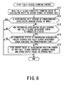
- Fig. 6 is a flowchart showing another example of fully closed learning control of the vehicle control device according to the embodiment of present invention.
- a process in Step S11 in Fig. 6 is the same as the process in Step S1 in Fig. 5
- a process in Steps S 13 to S 15 in Fig. 6 is the same as the process in Steps S2 to S4 in Fig. 5 , and thus repetitive descriptions will be omitted.
- the electric control unit 26 of the vehicle control device 21 stores, in the storage unit 79 of the electric control unit 26, the output value of the accelerator position sensor 56 when the accelerator pulley stopper 73 is in contact with the protrusion 72 on the accelerator pulley 71 and the fully closed adjustment screw 75 as the fully closed position of the accelerator grip 23 in case where the output value of the accelerator position sensor 56 is smaller than a predetermined value during cranking operation of the motorcycle 1.
- the output value of the accelerator position sensor 56 is the predetermined value or more, it is apparent that the accelerator grip 23 is not placed in the fully closed position.
- the previous fully closed corrected learning value of the accelerator position sensor 56 is maintained and the process is finished before the electric control unit 26 checks the conductive states of the protrusion 72 on the accelerator pulley 71, the accelerator pulley stopper 73, and the fully closed adjustment screw 75.
- the electric control unit 26 starts the learning control in the fully closed position of the accelerator grip 23.
- Step S12 the electric control unit 26 compares the output value of the accelerator position sensor 56 with the predetermined value, and determines whether the accelerator grip 23 is rotated at a predetermined accelerator opening degree or more, for example, an accelerator opening degree of 5% or more of a rotation amount from the fully closed position to the fully opened position.
- a predetermined accelerator opening degree or more for example, an accelerator opening degree of 5% or more of a rotation amount from the fully closed position to the fully opened position.
- the vehicle control device 21 thus configured can excessively rotate the accelerator grip 23 from the fully closed position according to the predetermined excessive rotation operational force F or more by the rider. Thus, even if the rider forgets the cruise control being performed because of careless driving or the like, the accelerator grip 23 is rotated in the closing direction and thus excessively rotated, and the vehicle control device 21 can detect a rider's intention to decelerate.
- the vehicle control device 21 detects the excessive rotation of the accelerator grip 23 with the accelerator position sensor 56 to automatically release the cruise control.
- the cruise control can be reliably released in addition to a case of the operation of any of the front brake switch 59, the rear brake switch 60, and the clutch switch 61, and there is no possibility of delay of the deceleration operation of the motorcycle 1 during the cruise control.
- the accelerator grip 23 that can be excessively rotated from the normal fully closed position in the further closing direction can be configured, and the excessive rotation of the accelerator grip 23 can be detected to automatically release the cruise control.
Landscapes
- Engineering & Computer Science (AREA)
- Mechanical Engineering (AREA)
- Chemical & Material Sciences (AREA)
- Combustion & Propulsion (AREA)
- General Engineering & Computer Science (AREA)
- Transportation (AREA)
- Control Of Throttle Valves Provided In The Intake System Or In The Exhaust System (AREA)
- Control Of Vehicle Engines Or Engines For Specific Uses (AREA)
- Control Of Driving Devices And Active Controlling Of Vehicle (AREA)
- Steering Devices For Bicycles And Motorcycles (AREA)
- Controls For Constant Speed Travelling (AREA)
Claims (3)
- Dispositif régulateur de vitesse (21) pour motocyclette incluant un système de commande des gaz électronique, le dispositif régulateur de vitesse (21) comprenant :un bloc de régulation (26) pour réaliser une régulation de vitesse ;une poignée d'accélérateur (23) ;un capteur de position d'accélérateur (24) destiné à détecter une quantité de rotation de la poignée d'accélérateur (23) ;un papillon des gaz (25) apte à être ouvert et fermé par le dispositif régulateur de vitesse (21) en fonction de la quantité de rotation de la poignée d'accélération (23) ;une poulie d'accélérateur (71) verrouillée avec la poignée d'accélérateur (23) ;une saillie (72) formée sur la poulie d'accélérateur (71) ;un ressort de rappel d'accélérateur (54) relié à la poignée d'accélérateur (23) destiné à solliciter la poignée d'accélérateur de manière à la faire tourner dans une direction de fermeture du papillon des gaz (25) ;dans lequel la poignée d'accélérateur (23) est apte à tourner en excès dans la direction de fermeture du papillon des gaz (25) d'une position entièrement fermée correspondant à un état entièrement fermé du papillon des gaz (25), lorsqu'une force opérationnelle prédéterminée (F) ou plus est appliquée à la poignée d'accélération (23) ;un arrêt de poulie d'accélérateur (73), qui est apte à être en contact avec la saillie (72) dans la position entièrement fermée de la poignée d'accélérateur (23) et durant la rotation excessive de la poignée d'accélérateur (23), etun ressort de support d'arrêt (74) qui est apte à appliquer une force de sollicitation, dans une direction opposée à une direction de la force de sollicitation du ressort de rappel d'accélérateur (54) et supérieure à la force de sollicitation du ressort de rappel d'accélérateur (54), pour que l'arrêt de poulie d'accélérateur (73) soit en contact avec la saillie (72),caractérisé en ce que l'arrêt de poulie d'accélérateur (73) dépend d'un tourillon pouvant pivoter sur un arbre-support (77),le dispositif régulateur de vitesse (21) comprenant en outre un élément d'ajustement du degré d'ouverture (75) qui est apte à ajuster une quantité de pivotement de l'arrêt de poulie d'accélérateur (73) et à restreindre une position de pivot initiale de l'arrêt de poulie d'accélérateur (73) contre la force de sollicitation du ressort de support d'arrêt (74) pour ajuster la position entièrement fermée de la poignée d'accélérateur (23),l'élément d'ajustement du degré d'ouverture (75) est apte à ne pas être en contact avec la saillie (72) durant la rotation excessive de la poignée d'accélérateur (23),la saillie (72), l'arrêt de poulie d'accélérateur (73) et l'élément d'ajustement du degré d'ouverture (75) sont fabriqués dans un matériau conducteur,le bloc de régulation (26) est apte à détecter un état conducteur entre la saillie (72), l'arrêt de poulie d'accélérateur (73) et l'élément d'ajustement du degré d'ouverture (75) lorsque la poignée d'accélérateur (23) est placée dans la position entièrement fermée de la poignée d'accélérateur (23), etle bloc de régulation (26) est apte à libérer le régulateur de vitesse lorsque le capteur de position d'accélérateur (24) détecte la rotation excessive de la poignée d'accélérateur (23).
- Dispositif régulateur de vitesse pour motocyclette incluant un système de commande des gaz électronique selon la revendication 1,
dans lequel le bloc de régulation (26) comprend un bloc de stockage (79) qui est apte à stocker une valeur de sortie du capteur de position d'accélérateur (24), et
le bloc de stockage (79) est apte à stocker la valeur de sortie comme la position entièrement fermée de la poignée d'accélérateur (23) lorsque l'arrêt de poulie d'accélérateur (73) est en contact avec la saillie (72) et l'élément d'ajustement du degré d'ouverture (75). - Dispositif régulateur de vitesse pour motocyclette incluant un système de commande des gaz électronique selon la revendication 2,
dans lequel le bloc de stockage (79) est apte à stocker la valeur de sortie du capteur de position d'accélérateur (24) comme la position entièrement fermée de la poignée d'accélérateur (23) durant l'opération de démarrage de la motocyclette.
Applications Claiming Priority (1)
| Application Number | Priority Date | Filing Date | Title |
|---|---|---|---|
| JP2009099639A JP2010247681A (ja) | 2009-04-16 | 2009-04-16 | 車両制御装置 |
Publications (2)
| Publication Number | Publication Date |
|---|---|
| EP2241498A1 EP2241498A1 (fr) | 2010-10-20 |
| EP2241498B1 true EP2241498B1 (fr) | 2014-07-30 |
Family
ID=42663612
Family Applications (1)
| Application Number | Title | Priority Date | Filing Date |
|---|---|---|---|
| EP10159820.9A Active EP2241498B1 (fr) | 2009-04-16 | 2010-04-13 | Régulateur de vitesse pour une motocyclette |
Country Status (4)
| Country | Link |
|---|---|
| US (1) | US8428851B2 (fr) |
| EP (1) | EP2241498B1 (fr) |
| JP (1) | JP2010247681A (fr) |
| ES (1) | ES2490241T3 (fr) |
Cited By (2)
| Publication number | Priority date | Publication date | Assignee | Title |
|---|---|---|---|---|
| DE102016224913A1 (de) | 2016-12-14 | 2018-06-14 | Robert Bosch Gmbh | Verfahren zur selbsttätigen Einstellung der Geschwindigkeit eines Motorrads |
| DE102018219027A1 (de) | 2018-11-08 | 2020-05-14 | Robert Bosch Gmbh | Verfahren und Vorrichtung zur fahrerunabhängigen temporären Deaktivierung einer Geschwindigkeitskonstanthaltefunktion für ein einspuriges Kraftfahrzeugs |
Families Citing this family (7)
| Publication number | Priority date | Publication date | Assignee | Title |
|---|---|---|---|---|
| JP5721256B2 (ja) * | 2011-01-24 | 2015-05-20 | 本田技研工業株式会社 | 電動車両の制御装置 |
| JP2014025348A (ja) | 2012-07-24 | 2014-02-06 | Yamaha Motor Co Ltd | 鞍乗型車両 |
| WO2014058055A1 (fr) * | 2012-10-12 | 2014-04-17 | ヤマハ発動機株式会社 | Ensemble poignée d'accélération, et véhicule doté d'un ensemble poignée d'accélération |
| CN106573661B (zh) * | 2014-06-04 | 2019-03-22 | 株式会社F.C.C. | 鞍乘型车辆 |
| JP7158189B2 (ja) * | 2018-07-11 | 2022-10-21 | 東洋電装株式会社 | スロットルグリップ装置 |
| CO2020014090A1 (es) * | 2019-11-15 | 2021-02-08 | Hero Motocorp Ltd | Sistema de arranque de vehiculo |
| JP2022053053A (ja) | 2020-09-24 | 2022-04-05 | ヤマハ発動機株式会社 | 自動二輪車 |
Family Cites Families (8)
| Publication number | Priority date | Publication date | Assignee | Title |
|---|---|---|---|---|
| EP0687588B1 (fr) | 1991-09-03 | 1999-01-07 | Honda Giken Kogyo Kabushiki Kaisha | Système de freinage à récupération d'énergie dans un véhicule à moteur |
| WO1999020482A1 (fr) * | 1997-10-22 | 1999-04-29 | G-Zero Technologies, Llc | Regulateur de vitesse pour motocycle |
| JP4218817B2 (ja) | 2000-03-03 | 2009-02-04 | 本田技研工業株式会社 | 自動二輪車の定車速保持装置 |
| US6820710B2 (en) * | 2001-09-12 | 2004-11-23 | Bryan W. Fechner | Motorcycle cruise control system with brake release |
| JP4414389B2 (ja) * | 2005-10-18 | 2010-02-10 | 本田技研工業株式会社 | 鞍乗り型車両 |
| DK2032423T3 (da) | 2006-06-14 | 2012-07-16 | Vectrix Internat Ltd | Køretøjseffektstyring |
| US7315779B1 (en) * | 2006-12-22 | 2008-01-01 | Bombardier Recreational Products Inc. | Vehicle speed limiter |
| US8640566B2 (en) | 2007-07-03 | 2014-02-04 | Honda Motor Co., Ltd. | Throttle device for vehicle |
-
2009
- 2009-04-16 JP JP2009099639A patent/JP2010247681A/ja active Pending
-
2010
- 2010-04-09 US US12/757,116 patent/US8428851B2/en active Active
- 2010-04-13 EP EP10159820.9A patent/EP2241498B1/fr active Active
- 2010-04-13 ES ES10159820.9T patent/ES2490241T3/es active Active
Cited By (4)
| Publication number | Priority date | Publication date | Assignee | Title |
|---|---|---|---|---|
| DE102016224913A1 (de) | 2016-12-14 | 2018-06-14 | Robert Bosch Gmbh | Verfahren zur selbsttätigen Einstellung der Geschwindigkeit eines Motorrads |
| WO2018108436A1 (fr) | 2016-12-14 | 2018-06-21 | Robert Bosch Gmbh | Procédé de régulation automatique de la vitesse d'une motocyclette |
| US11247676B2 (en) | 2016-12-14 | 2022-02-15 | Robert Bosch Gmbh | Method for automatically adjusting the speed of a motorcycle |
| DE102018219027A1 (de) | 2018-11-08 | 2020-05-14 | Robert Bosch Gmbh | Verfahren und Vorrichtung zur fahrerunabhängigen temporären Deaktivierung einer Geschwindigkeitskonstanthaltefunktion für ein einspuriges Kraftfahrzeugs |
Also Published As
| Publication number | Publication date |
|---|---|
| JP2010247681A (ja) | 2010-11-04 |
| US8428851B2 (en) | 2013-04-23 |
| ES2490241T3 (es) | 2014-09-03 |
| US20100268431A1 (en) | 2010-10-21 |
| EP2241498A1 (fr) | 2010-10-20 |
Similar Documents
| Publication | Publication Date | Title |
|---|---|---|
| EP2241498B1 (fr) | Régulateur de vitesse pour une motocyclette | |
| US7458915B2 (en) | Leisure vehicle | |
| EP2103800B1 (fr) | Système d'admission et moto le comportant | |
| US7311082B2 (en) | Straddle type vehicle having an electronic throttle valve system | |
| US8160790B2 (en) | Vehicle speed control system and straddle-type vehicle | |
| US9482170B2 (en) | Deceleration control system in a vehicle, vehicle including a deceleration control system, and deceleration control method | |
| US7287511B2 (en) | Engine for leisure vehicle | |
| EP1717091B1 (fr) | Procédé et dispositif de contrôle d'un moteur, programme d'ordinateur pour ce contrôle et support d'enregistrement | |
| EP2249010A2 (fr) | Appareil de commande de manette électrique pour motocyclette | |
| US20080178839A1 (en) | Idling engine speed control system for a vehicle and vehicle equipped with idling engine speed control system | |
| US20080178840A1 (en) | Electronic control throttle system for a vehicle and vehicle equipped therewith | |
| US8498800B2 (en) | Engine control unit | |
| EP2159400B1 (fr) | Système de commande et véhicule | |
| US8826885B2 (en) | Fuel injection control system | |
| US7883443B2 (en) | Method and system for controlling an engine for a vehicle, and a motorcycle | |
| US8700289B2 (en) | Straddle type vehicle | |
| JP5195495B2 (ja) | 電子制御スロットルバルブシステム | |
| US8574126B2 (en) | Vehicle and fuel feed stop controller | |
| WO2016152010A1 (fr) | Système de propulseur et véhicule du type à selle | |
| US7441547B2 (en) | Method of feeding fuel to an engine, fuel feed amount control system of an engine, and motorcycle comprising fuel feed amount control system | |
| EP2149692A2 (fr) | Démarrage puor moteur a à combustion interne avec deux combustibles | |
| JP6044354B2 (ja) | 車両 | |
| JP2004156546A (ja) | スロットルバルブ制御装置 | |
| WO2018173187A1 (fr) | Dispositif de commande pour moteur à combustion interne | |
| JP2012211550A (ja) | 車両 |
Legal Events
| Date | Code | Title | Description |
|---|---|---|---|
| PUAI | Public reference made under article 153(3) epc to a published international application that has entered the european phase |
Free format text: ORIGINAL CODE: 0009012 |
|
| 17P | Request for examination filed |
Effective date: 20100413 |
|
| AK | Designated contracting states |
Kind code of ref document: A1 Designated state(s): AT BE BG CH CY CZ DE DK EE ES FI FR GB GR HR HU IE IS IT LI LT LU LV MC MK MT NL NO PL PT RO SE SI SK SM TR |
|
| AX | Request for extension of the european patent |
Extension state: AL BA ME RS |
|
| RIN1 | Information on inventor provided before grant (corrected) |
Inventor name: ITAGAKI, KATSUHIKO |
|
| 17Q | First examination report despatched |
Effective date: 20130805 |
|
| RIC1 | Information provided on ipc code assigned before grant |
Ipc: B62K 23/04 20060101AFI20140109BHEP Ipc: F02D 41/24 20060101ALI20140109BHEP Ipc: B60K 26/02 20060101ALI20140109BHEP Ipc: B60K 31/04 20060101ALI20140109BHEP Ipc: F02D 11/02 20060101ALI20140109BHEP |
|
| GRAP | Despatch of communication of intention to grant a patent |
Free format text: ORIGINAL CODE: EPIDOSNIGR1 |
|
| INTG | Intention to grant announced |
Effective date: 20140318 |
|
| GRAS | Grant fee paid |
Free format text: ORIGINAL CODE: EPIDOSNIGR3 |
|
| GRAA | (expected) grant |
Free format text: ORIGINAL CODE: 0009210 |
|
| AK | Designated contracting states |
Kind code of ref document: B1 Designated state(s): AT BE BG CH CY CZ DE DK EE ES FI FR GB GR HR HU IE IS IT LI LT LU LV MC MK MT NL NO PL PT RO SE SI SK SM TR |
|
| REG | Reference to a national code |
Ref country code: GB Ref legal event code: FG4D |
|
| REG | Reference to a national code |
Ref country code: CH Ref legal event code: EP |
|
| REG | Reference to a national code |
Ref country code: AT Ref legal event code: REF Ref document number: 679819 Country of ref document: AT Kind code of ref document: T Effective date: 20140815 |
|
| REG | Reference to a national code |
Ref country code: IE Ref legal event code: FG4D |
|
| REG | Reference to a national code |
Ref country code: ES Ref legal event code: FG2A Ref document number: 2490241 Country of ref document: ES Kind code of ref document: T3 Effective date: 20140903 |
|
| REG | Reference to a national code |
Ref country code: DE Ref legal event code: R096 Ref document number: 602010017841 Country of ref document: DE Effective date: 20140911 |
|
| REG | Reference to a national code |
Ref country code: AT Ref legal event code: MK05 Ref document number: 679819 Country of ref document: AT Kind code of ref document: T Effective date: 20140730 |
|
| REG | Reference to a national code |
Ref country code: NL Ref legal event code: VDEP Effective date: 20140730 |
|
| REG | Reference to a national code |
Ref country code: LT Ref legal event code: MG4D |
|
| PG25 | Lapsed in a contracting state [announced via postgrant information from national office to epo] |
Ref country code: NO Free format text: LAPSE BECAUSE OF FAILURE TO SUBMIT A TRANSLATION OF THE DESCRIPTION OR TO PAY THE FEE WITHIN THE PRESCRIBED TIME-LIMIT Effective date: 20141030 Ref country code: SE Free format text: LAPSE BECAUSE OF FAILURE TO SUBMIT A TRANSLATION OF THE DESCRIPTION OR TO PAY THE FEE WITHIN THE PRESCRIBED TIME-LIMIT Effective date: 20140730 Ref country code: GR Free format text: LAPSE BECAUSE OF FAILURE TO SUBMIT A TRANSLATION OF THE DESCRIPTION OR TO PAY THE FEE WITHIN THE PRESCRIBED TIME-LIMIT Effective date: 20141031 Ref country code: BG Free format text: LAPSE BECAUSE OF FAILURE TO SUBMIT A TRANSLATION OF THE DESCRIPTION OR TO PAY THE FEE WITHIN THE PRESCRIBED TIME-LIMIT Effective date: 20141030 Ref country code: PT Free format text: LAPSE BECAUSE OF FAILURE TO SUBMIT A TRANSLATION OF THE DESCRIPTION OR TO PAY THE FEE WITHIN THE PRESCRIBED TIME-LIMIT Effective date: 20141202 Ref country code: FI Free format text: LAPSE BECAUSE OF FAILURE TO SUBMIT A TRANSLATION OF THE DESCRIPTION OR TO PAY THE FEE WITHIN THE PRESCRIBED TIME-LIMIT Effective date: 20140730 Ref country code: LT Free format text: LAPSE BECAUSE OF FAILURE TO SUBMIT A TRANSLATION OF THE DESCRIPTION OR TO PAY THE FEE WITHIN THE PRESCRIBED TIME-LIMIT Effective date: 20140730 |
|
| PG25 | Lapsed in a contracting state [announced via postgrant information from national office to epo] |
Ref country code: CY Free format text: LAPSE BECAUSE OF FAILURE TO SUBMIT A TRANSLATION OF THE DESCRIPTION OR TO PAY THE FEE WITHIN THE PRESCRIBED TIME-LIMIT Effective date: 20140730 Ref country code: NL Free format text: LAPSE BECAUSE OF FAILURE TO SUBMIT A TRANSLATION OF THE DESCRIPTION OR TO PAY THE FEE WITHIN THE PRESCRIBED TIME-LIMIT Effective date: 20140730 Ref country code: AT Free format text: LAPSE BECAUSE OF FAILURE TO SUBMIT A TRANSLATION OF THE DESCRIPTION OR TO PAY THE FEE WITHIN THE PRESCRIBED TIME-LIMIT Effective date: 20140730 Ref country code: PL Free format text: LAPSE BECAUSE OF FAILURE TO SUBMIT A TRANSLATION OF THE DESCRIPTION OR TO PAY THE FEE WITHIN THE PRESCRIBED TIME-LIMIT Effective date: 20140730 Ref country code: HR Free format text: LAPSE BECAUSE OF FAILURE TO SUBMIT A TRANSLATION OF THE DESCRIPTION OR TO PAY THE FEE WITHIN THE PRESCRIBED TIME-LIMIT Effective date: 20140730 Ref country code: LV Free format text: LAPSE BECAUSE OF FAILURE TO SUBMIT A TRANSLATION OF THE DESCRIPTION OR TO PAY THE FEE WITHIN THE PRESCRIBED TIME-LIMIT Effective date: 20140730 Ref country code: IS Free format text: LAPSE BECAUSE OF FAILURE TO SUBMIT A TRANSLATION OF THE DESCRIPTION OR TO PAY THE FEE WITHIN THE PRESCRIBED TIME-LIMIT Effective date: 20141130 |
|
| PG25 | Lapsed in a contracting state [announced via postgrant information from national office to epo] |
Ref country code: EE Free format text: LAPSE BECAUSE OF FAILURE TO SUBMIT A TRANSLATION OF THE DESCRIPTION OR TO PAY THE FEE WITHIN THE PRESCRIBED TIME-LIMIT Effective date: 20140730 Ref country code: RO Free format text: LAPSE BECAUSE OF FAILURE TO SUBMIT A TRANSLATION OF THE DESCRIPTION OR TO PAY THE FEE WITHIN THE PRESCRIBED TIME-LIMIT Effective date: 20140730 Ref country code: SK Free format text: LAPSE BECAUSE OF FAILURE TO SUBMIT A TRANSLATION OF THE DESCRIPTION OR TO PAY THE FEE WITHIN THE PRESCRIBED TIME-LIMIT Effective date: 20140730 Ref country code: DK Free format text: LAPSE BECAUSE OF FAILURE TO SUBMIT A TRANSLATION OF THE DESCRIPTION OR TO PAY THE FEE WITHIN THE PRESCRIBED TIME-LIMIT Effective date: 20140730 Ref country code: CZ Free format text: LAPSE BECAUSE OF FAILURE TO SUBMIT A TRANSLATION OF THE DESCRIPTION OR TO PAY THE FEE WITHIN THE PRESCRIBED TIME-LIMIT Effective date: 20140730 |
|
| REG | Reference to a national code |
Ref country code: DE Ref legal event code: R097 Ref document number: 602010017841 Country of ref document: DE |
|
| PLBE | No opposition filed within time limit |
Free format text: ORIGINAL CODE: 0009261 |
|
| STAA | Information on the status of an ep patent application or granted ep patent |
Free format text: STATUS: NO OPPOSITION FILED WITHIN TIME LIMIT |
|
| 26N | No opposition filed |
Effective date: 20150504 |
|
| REG | Reference to a national code |
Ref country code: DE Ref legal event code: R119 Ref document number: 602010017841 Country of ref document: DE |
|
| PG25 | Lapsed in a contracting state [announced via postgrant information from national office to epo] |
Ref country code: SI Free format text: LAPSE BECAUSE OF FAILURE TO SUBMIT A TRANSLATION OF THE DESCRIPTION OR TO PAY THE FEE WITHIN THE PRESCRIBED TIME-LIMIT Effective date: 20140730 Ref country code: LU Free format text: LAPSE BECAUSE OF FAILURE TO SUBMIT A TRANSLATION OF THE DESCRIPTION OR TO PAY THE FEE WITHIN THE PRESCRIBED TIME-LIMIT Effective date: 20150413 Ref country code: MC Free format text: LAPSE BECAUSE OF FAILURE TO SUBMIT A TRANSLATION OF THE DESCRIPTION OR TO PAY THE FEE WITHIN THE PRESCRIBED TIME-LIMIT Effective date: 20140730 |
|
| REG | Reference to a national code |
Ref country code: CH Ref legal event code: PL |
|
| GBPC | Gb: european patent ceased through non-payment of renewal fee |
Effective date: 20150413 |
|
| REG | Reference to a national code |
Ref country code: IE Ref legal event code: MM4A |
|
| PG25 | Lapsed in a contracting state [announced via postgrant information from national office to epo] |
Ref country code: DE Free format text: LAPSE BECAUSE OF NON-PAYMENT OF DUE FEES Effective date: 20151103 Ref country code: LI Free format text: LAPSE BECAUSE OF NON-PAYMENT OF DUE FEES Effective date: 20150430 Ref country code: GB Free format text: LAPSE BECAUSE OF NON-PAYMENT OF DUE FEES Effective date: 20150413 Ref country code: CH Free format text: LAPSE BECAUSE OF NON-PAYMENT OF DUE FEES Effective date: 20150430 |
|
| REG | Reference to a national code |
Ref country code: FR Ref legal event code: ST Effective date: 20151231 |
|
| PG25 | Lapsed in a contracting state [announced via postgrant information from national office to epo] |
Ref country code: FR Free format text: LAPSE BECAUSE OF NON-PAYMENT OF DUE FEES Effective date: 20150430 |
|
| PG25 | Lapsed in a contracting state [announced via postgrant information from national office to epo] |
Ref country code: IE Free format text: LAPSE BECAUSE OF NON-PAYMENT OF DUE FEES Effective date: 20150413 |
|
| PG25 | Lapsed in a contracting state [announced via postgrant information from national office to epo] |
Ref country code: BE Free format text: LAPSE BECAUSE OF FAILURE TO SUBMIT A TRANSLATION OF THE DESCRIPTION OR TO PAY THE FEE WITHIN THE PRESCRIBED TIME-LIMIT Effective date: 20140730 |
|
| PG25 | Lapsed in a contracting state [announced via postgrant information from national office to epo] |
Ref country code: MT Free format text: LAPSE BECAUSE OF FAILURE TO SUBMIT A TRANSLATION OF THE DESCRIPTION OR TO PAY THE FEE WITHIN THE PRESCRIBED TIME-LIMIT Effective date: 20140730 |
|
| PG25 | Lapsed in a contracting state [announced via postgrant information from national office to epo] |
Ref country code: SM Free format text: LAPSE BECAUSE OF FAILURE TO SUBMIT A TRANSLATION OF THE DESCRIPTION OR TO PAY THE FEE WITHIN THE PRESCRIBED TIME-LIMIT Effective date: 20140730 Ref country code: HU Free format text: LAPSE BECAUSE OF FAILURE TO SUBMIT A TRANSLATION OF THE DESCRIPTION OR TO PAY THE FEE WITHIN THE PRESCRIBED TIME-LIMIT; INVALID AB INITIO Effective date: 20100413 |
|
| PG25 | Lapsed in a contracting state [announced via postgrant information from national office to epo] |
Ref country code: TR Free format text: LAPSE BECAUSE OF FAILURE TO SUBMIT A TRANSLATION OF THE DESCRIPTION OR TO PAY THE FEE WITHIN THE PRESCRIBED TIME-LIMIT Effective date: 20140730 |
|
| PG25 | Lapsed in a contracting state [announced via postgrant information from national office to epo] |
Ref country code: MK Free format text: LAPSE BECAUSE OF FAILURE TO SUBMIT A TRANSLATION OF THE DESCRIPTION OR TO PAY THE FEE WITHIN THE PRESCRIBED TIME-LIMIT Effective date: 20140730 |
|
| PGFP | Annual fee paid to national office [announced via postgrant information from national office to epo] |
Ref country code: IT Payment date: 20230310 Year of fee payment: 14 |
|
| PGFP | Annual fee paid to national office [announced via postgrant information from national office to epo] |
Ref country code: ES Payment date: 20230505 Year of fee payment: 14 |