EP2241425A1 - Method of machining component parts of wood or similar, in particular door and window frame component parts - Google Patents
Method of machining component parts of wood or similar, in particular door and window frame component parts Download PDFInfo
- Publication number
- EP2241425A1 EP2241425A1 EP10172236A EP10172236A EP2241425A1 EP 2241425 A1 EP2241425 A1 EP 2241425A1 EP 10172236 A EP10172236 A EP 10172236A EP 10172236 A EP10172236 A EP 10172236A EP 2241425 A1 EP2241425 A1 EP 2241425A1
- Authority
- EP
- European Patent Office
- Prior art keywords
- machining
- clamp
- grip
- component part
- component parts
- Prior art date
- Legal status (The legal status is an assumption and is not a legal conclusion. Google has not performed a legal analysis and makes no representation as to the accuracy of the status listed.)
- Granted
Links
- 238000003754 machining Methods 0.000 title claims abstract description 47
- 238000000034 method Methods 0.000 title claims abstract description 28
- 239000002023 wood Substances 0.000 title claims abstract description 9
- 238000003780 insertion Methods 0.000 claims description 5
- 230000037431 insertion Effects 0.000 claims description 5
- 230000009977 dual effect Effects 0.000 description 1
Images


Classifications
-
- B—PERFORMING OPERATIONS; TRANSPORTING
- B27—WORKING OR PRESERVING WOOD OR SIMILAR MATERIAL; NAILING OR STAPLING MACHINES IN GENERAL
- B27M—WORKING OF WOOD NOT PROVIDED FOR IN SUBCLASSES B27B - B27L; MANUFACTURE OF SPECIFIC WOODEN ARTICLES
- B27M1/00—Working of wood not provided for in subclasses B27B - B27L, e.g. by stretching
- B27M1/08—Working of wood not provided for in subclasses B27B - B27L, e.g. by stretching by multi-step processes
-
- B—PERFORMING OPERATIONS; TRANSPORTING
- B27—WORKING OR PRESERVING WOOD OR SIMILAR MATERIAL; NAILING OR STAPLING MACHINES IN GENERAL
- B27F—DOVETAILED WORK; TENONS; SLOTTING MACHINES FOR WOOD OR SIMILAR MATERIAL; NAILING OR STAPLING MACHINES
- B27F1/00—Dovetailed work; Tenons; Making tongues or grooves; Groove- and- tongue jointed work; Finger- joints
- B27F1/02—Making tongues or grooves, of indefinite length
- B27F1/04—Making tongues or grooves, of indefinite length along only one edge of a board
Definitions
- the present invention relates to a method of machining component parts of wood or similar, in particular door and window frame component parts.
- Door and window frame component parts are known to be machined on a machine of the type comprising an elongated bed with two longitudinal guide members; a number of cross members fitted in sliding manner to the longitudinal members; at least one clamp fitted to each cross member to clamp the component parts for machining; a bridge movable along the bed in a first direction; and a machining head movable along the bridge in a second direction crosswise to the first.
- the clamps are normally movable along the cross members in the second direction by means of respective actuating devices to machine the two opposite sides of each component part.
- the component part is first clamped by at least one first clamp to enable the machining head to machine a first side of the component part, and is then gripped along the first side by at least one second clamp to remove the component part from the first clamp and enable the machining head to machine a second side of the component part.
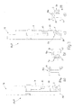
- Number 1 in Figure 1 indicates as a whole a machine for machining door and window frame component parts 2 of wood or similar, and which comprises an elongated, substantially U-shaped bed 3 extending in a horizontal direction 4 and having two lateral longitudinal members 5 extending parallel to direction 4 and each supporting a respective rail 6 also parallel to direction 4.
- Machine 1 also comprises a bridge 7, in turn comprising an upright 8 which is fitted in known manner to bed 3, is moved linearly in direction 4 along bed 3 by a known actuating device not shown, and is fitted on its free end with a cross member 9 extending over bed 3 in a horizontal direction 10 crosswise to direction 4, and bounded laterally by two opposite faces 11, 12 substantially perpendicular to direction 4.
- Bridge 7 supports a known machining head 13 which is fitted to face 11, is fitted in known manner to cross member 9 to move linearly along cross member 9 in direction 10, and comprises at least one tool spindle (not shown) fitted in known manner to head 13 to move in a vertical direction 14 perpendicular to directions 4 and 10.
- Machine 1 also comprises a number of cross members 15 - hereinafter referred to as "work surfaces” - which extend between rails 6 in direction 10, and are fitted to rails 6 to slide manually, or by means of respective known actuating devices not shown, along rails 6 in direction 4.
- Work surfaces 15 support a number of clamps 16, the arrangement of which on relative work surfaces 15 substantially depends on the size of, and the type of work to be carried out on, component parts 2.
- each clamp 16 comprises a fixed bottom jaw 17 fixed to relative work surface 15 and defining, with jaws 17 of the other clamps 16, a substantially horizontal supporting surface P1 for at least one component part 2; and a movable top jaw 18 which extends parallel to surface P1, is fitted to the free end of an output rod (not shown) of an actuating cylinder (not shown), and is moved by the actuating cylinder (not shown) between a clamped position ( Figure 1 ) and a release position respectively clamping and releasing component part 2.
- Machine 1 also comprises a feed device 19 for component parts 2, which comprises a bed 20 located alongside bed 3 in direction 4 and supporting a number of belt conveyors 21, which are aligned in direction 4, extend in respective vertical planes parallel to one another and to direction 10, and have respective coplanar top conveying branches defining a horizontal conveying surface P2 parallel to surface P1.
- a feed device 19 for component parts 2 which comprises a bed 20 located alongside bed 3 in direction 4 and supporting a number of belt conveyors 21, which are aligned in direction 4, extend in respective vertical planes parallel to one another and to direction 10, and have respective coplanar top conveying branches defining a horizontal conveying surface P2 parallel to surface P1.
- Conveyors 21 extend in direction 10 between a loading station 22 where component parts 2 for machining are loaded onto device 19, and an unloading station 23 where component parts 2 for machining are unloaded off device 19.
- Component parts 2 are transferred between clamps 16 and feed device 19 by a grip-and-carry assembly 24 comprising an arm 25, which projects in direction 4 from face 12 of cross member 9, is fitted in known manner to cross member 9 to move linearly along cross member 9 in direction 10 under the control of a known actuating device not shown, and is fitted, in the example shown, with two grip-and-carry device 26, 27 movable with respect to each other in direction 4.
- a grip-and-carry assembly 24 comprising an arm 25, which projects in direction 4 from face 12 of cross member 9, is fitted in known manner to cross member 9 to move linearly along cross member 9 in direction 10 under the control of a known actuating device not shown, and is fitted, in the example shown, with two grip-and-carry device 26, 27 movable with respect to each other in direction 4.
- device 26 is fixed to arm 25 in direction 4, while device 27 is fitted in known manner to arm 25 to move linearly along arm 25 in direction 4 under the control of a known actuating device not shown.
- each device 26, 27 comprises a gripper, in turn comprising a substantially L-shaped bottom jaw 28 movable in direction 14 under the control of a known actuating device not shown; and a top jaw 29 which is fitted to the free end of an output rod 30 of an actuating cylinder 31 fixed to jaw 28, and is moved by actuating cylinder 31 between a grip position and a release position respectively gripping and releasing component part 2.
- component parts 2 are loaded successively onto device 19 at loading station 22, either manually or by means of a known loader not shown, are positioned contacting at least two known stops (not shown) located at station 22 to ensure each component part 2 is positioned correctly in direction 10, and are then fed successively in steps to unloading station 23.
- component parts 2 are loaded onto feed device 19, the component part 2 located at station 23 is transferred by grip-and-carry assembly 24 to clamps 16 for machining by machining head 13, feed device 19 is operated to move another component part 2 into station 23, and the machined component part 2 is transferred by assembly 24 from clamps 16 to station 22.
- the component part 2 unloaded at station 22 is then moved forward, behind the component parts 2 already unloaded at station 22 ( Figure 2 ), by a push device (not shown) operated independently of feed device 19 when device 19 is stopped.
- the component part 2 for machining is picked up from station 23 by assembly 24; is inserted by assembly 24 inside at least one first clamp 16 (hereinafter indicated 16a) in an insertion direction 10a parallel to direction 10 ( Figure 3a ) to enable machining head 13 to machine a first side 2a of component part 2 ( Figure 3b ); is withdrawn from clamp 16a by assembly 24 ( Figure 3c ); and is inserted by assembly 24 inside at least one second clamp 16 (hereinafter indicated 16b) in an insertion direction 10b parallel to and opposite direction 10a, to enable machining head 13 to machine a second side 2b, opposite side 2a, of component part 2 ( Figure 3d ).
- component part 2 may be withdrawn from clamp 16a, moved in directions 10 and 14 onto the opposite side of clamp 16a, and inserted once more into the same clamp 16a in direction 10b to also machine side 2b.
- grip-and-carry devices 26, 27 are replaced by respective dual grip-and-carry devices 32, 33, each comprising a respective slide 34, which is movable in direction 14 and supports two superimposed grippers 35, 36, with gripper 35 located over gripper 36.
- Gripper 35 comprises a bottom jaw 37 projecting in direction 10 from slide 34 and cooperating with a top jaw 38, which is movable in direction 14, with respect to slide 34 and under the control of an actuating cylinder 39 fixed to slide 34, between a grip position and a release position respectively gripping and releasing a first component part 2; and gripper 36 comprises a top jaw defined by bottom jaw 37 of gripper 35, and a bottom jaw 40, which is movable in direction 14, with respect to slide 34 and under the control of an actuating cylinder 41 fixed to slide 34, between a grip position and a release position respectively gripping and releasing a second component part 2.
- slide 34 of device 33 is in turn fitted to a slide (not shown) movable in direction 4 along arm 25.
- grip-and-carry assembly 24 in Figure 4 In actual use, at each operating cycle, grip-and-carry assembly 24 in Figure 4 :
- feed device 19 is replaced by two feed devices 42, which are identical to device 19, define two parallel, superimposed supporting surfaces P2, and are located one (hereinafter indicated 42a) over the other (hereinafter indicated 42b).
- Device 42a extends between loading station 22 and unloading station 23, and successively feeds component parts 2 for machining from station 22 to station 23; and device 42b feeds the machined component part 2 from an input station 43, projecting beyond station 23 in direction 10, to an output station 44 opposite station 43 and located at station 22.
- device 42b is associated with a lifting device 45 comprising a substantially vertical supporting beam 46 facing bed 20 of devices 42a, 42b in direction 10; and a number of arms 47, which project from beam 46 in direction 10, are offset with respect to belt conveyors 21 of device 42b in direction 4, and define a supporting surface P3 for at least one machined component part 2.
- Beam 46 is movable in direction 14 between a raised position, in which device 45 receives the machined component part 2 from assembly 24, and a lowered position, in which arms 47 are positioned between conveyors 21, and surface P3 is positioned below surface P2 of device 42b.
- component parts 2 for machining are fed successively by device 42a from loading station 22 to unloading station 23, are picked up successively at station 23 by assembly 24, are transferred to clamps 16, and are machined by head 13.
- the machined component parts 2 are removed from clamps 16 by assembly 24, are released by assembly 24 onto surface P3 when device 45 is in the raised position, are lowered by device 45 at input station 43, are released by device 45 onto device 42b, and are fed by device 42b to output station 44.
- lifting device 45 may be eliminated, and the machined component parts 2 released directly by assembly 24 at input station 43 of device 42b.
- component parts 2 for machining may be loaded onto device 42a at station 22, and the machined component parts 2 unloaded off device 42b at station 44 either manually or automatically by means of respective feed devices, possibly associated with further machines identical to machine 1.
- bridge 7 supports machining head 13 only, and grip-and-carry assembly 24 is fitted to a further bridge identical to bridge 7.
Landscapes
- Engineering & Computer Science (AREA)
- Life Sciences & Earth Sciences (AREA)
- Mechanical Engineering (AREA)
- Wood Science & Technology (AREA)
- Forests & Forestry (AREA)
- Milling, Drilling, And Turning Of Wood (AREA)
- Feeding Of Workpieces (AREA)
- Automatic Assembly (AREA)
- Multi-Process Working Machines And Systems (AREA)
- Chemical And Physical Treatments For Wood And The Like (AREA)
- Door And Window Frames Mounted To Openings (AREA)
Abstract
Description
- The present invention relates to a method of machining component parts of wood or similar, in particular door and window frame component parts.
- Door and window frame component parts are known to be machined on a machine of the type comprising an elongated bed with two longitudinal guide members; a number of cross members fitted in sliding manner to the longitudinal members; at least one clamp fitted to each cross member to clamp the component parts for machining; a bridge movable along the bed in a first direction; and a machining head movable along the bridge in a second direction crosswise to the first.
- The clamps are normally movable along the cross members in the second direction by means of respective actuating devices to machine the two opposite sides of each component part. In actual use, the component part is first clamped by at least one first clamp to enable the machining head to machine a first side of the component part, and is then gripped along the first side by at least one second clamp to remove the component part from the first clamp and enable the machining head to machine a second side of the component part.
- Known machines of the above type for working component parts of wood or similar have several drawbacks, mainly due to comprising an actuating device for each clamp, which makes them relatively complicated and expensive.
- It is an object of the present invention to provide a method of machining component parts of wood or similar, designed to eliminate the above drawbacks, and which is cheap and easy to implement.
- According to the present invention, there is provided a method of machining component parts of wood or similar, as claimed in the accompanying Claims.
- A non-limiting embodiment of the present invention will be described by way of example with reference to the accompanying drawings, in which:
-
Figure 1 shows a schematic view in perspective of a preferred embodiment of the machine according to the present invention; -
Figure 2 shows a schematic side view of theFigure 1 machine; -
Figure 3 shows, schematically, one operating mode of theFigure 1 and2 machine; -
Figure 4 shows a schematic side view of a variation of a first detail of theFigure 1 and2 machine; -
Figure 5 shows a schematic side view of a variation of a second detail of theFigure 1 and2 machine. -
Number 1 inFigure 1 indicates as a whole a machine for machining door and windowframe component parts 2 of wood or similar, and which comprises an elongated, substantiallyU-shaped bed 3 extending in a horizontal direction 4 and having two laterallongitudinal members 5 extending parallel to direction 4 and each supporting arespective rail 6 also parallel to direction 4. -
Machine 1 also comprises abridge 7, in turn comprising an upright 8 which is fitted in known manner tobed 3, is moved linearly in direction 4 alongbed 3 by a known actuating device not shown, and is fitted on its free end with across member 9 extending overbed 3 in ahorizontal direction 10 crosswise to direction 4, and bounded laterally by twoopposite faces -
Bridge 7 supports a knownmachining head 13 which is fitted toface 11, is fitted in known manner to crossmember 9 to move linearly alongcross member 9 indirection 10, and comprises at least one tool spindle (not shown) fitted in known manner tohead 13 to move in avertical direction 14 perpendicular todirections 4 and 10. -
Machine 1 also comprises a number of cross members 15 - hereinafter referred to as "work surfaces" - which extend betweenrails 6 indirection 10, and are fitted torails 6 to slide manually, or by means of respective known actuating devices not shown, alongrails 6 in direction 4. -
Work surfaces 15 support a number ofclamps 16, the arrangement of which onrelative work surfaces 15 substantially depends on the size of, and the type of work to be carried out on,component parts 2. - In the example shown, each
clamp 16 comprises afixed bottom jaw 17 fixed torelative work surface 15 and defining, withjaws 17 of theother clamps 16, a substantially horizontal supporting surface P1 for at least onecomponent part 2; and amovable top jaw 18 which extends parallel to surface P1, is fitted to the free end of an output rod (not shown) of an actuating cylinder (not shown), and is moved by the actuating cylinder (not shown) between a clamped position (Figure 1 ) and a release position respectively clamping and releasingcomponent part 2. -
Machine 1 also comprises afeed device 19 forcomponent parts 2, which comprises abed 20 located alongsidebed 3 in direction 4 and supporting a number ofbelt conveyors 21, which are aligned in direction 4, extend in respective vertical planes parallel to one another and todirection 10, and have respective coplanar top conveying branches defining a horizontal conveying surface P2 parallel to surface P1. -
Conveyors 21 extend indirection 10 between aloading station 22 wherecomponent parts 2 for machining are loaded ontodevice 19, and anunloading station 23 wherecomponent parts 2 for machining are unloaded offdevice 19. -
Component parts 2 are transferred betweenclamps 16 andfeed device 19 by a grip-and-carry assembly 24 comprising anarm 25, which projects in direction 4 fromface 12 ofcross member 9, is fitted in known manner to crossmember 9 to move linearly alongcross member 9 indirection 10 under the control of a known actuating device not shown, and is fitted, in the example shown, with two grip-and-carry device - In the example shown,
device 26 is fixed toarm 25 in direction 4, whiledevice 27 is fitted in known manner to arm 25 to move linearly alongarm 25 in direction 4 under the control of a known actuating device not shown. - With reference to
Figure 2 , eachdevice shaped bottom jaw 28 movable indirection 14 under the control of a known actuating device not shown; and atop jaw 29 which is fitted to the free end of anoutput rod 30 of an actuatingcylinder 31 fixed tojaw 28, and is moved by actuatingcylinder 31 between a grip position and a release position respectively gripping and releasingcomponent part 2. - In actual use,
component parts 2 are loaded successively ontodevice 19 atloading station 22, either manually or by means of a known loader not shown, are positioned contacting at least two known stops (not shown) located atstation 22 to ensure eachcomponent part 2 is positioned correctly indirection 10, and are then fed successively in steps to unloadingstation 23. - Once
component parts 2 are loaded ontofeed device 19, thecomponent part 2 located atstation 23 is transferred by grip-and-carry assembly 24 toclamps 16 for machining by machininghead 13,feed device 19 is operated to move anothercomponent part 2 intostation 23, and themachined component part 2 is transferred byassembly 24 fromclamps 16 tostation 22. - The
component part 2 unloaded atstation 22 is then moved forward, behind thecomponent parts 2 already unloaded at station 22 (Figure 2 ), by a push device (not shown) operated independently offeed device 19 whendevice 19 is stopped. - The above operating sequence is repeated for all the
component parts 2 loaded ontodevice 19, so as to gradually replace thecomponent parts 2 to be machined with the machinedcomponent parts 2. - In the
Figure 3 operating mode, thecomponent part 2 for machining is picked up fromstation 23 byassembly 24; is inserted byassembly 24 inside at least one first clamp 16 (hereinafter indicated 16a) in aninsertion direction 10a parallel to direction 10 (Figure 3a ) to enable machininghead 13 to machine afirst side 2a of component part 2 (Figure 3b ); is withdrawn fromclamp 16a by assembly 24 (Figure 3c ); and is inserted byassembly 24 inside at least one second clamp 16 (hereinafter indicated 16b) in aninsertion direction 10b parallel to andopposite direction 10a, to enable machininghead 13 to machine asecond side 2b,opposite side 2a, of component part 2 (Figure 3d ). - Obviously, once
side 2a is machined,component part 2 may be withdrawn fromclamp 16a, moved indirections clamp 16a, and inserted once more into thesame clamp 16a indirection 10b to alsomachine side 2b. - As will be clear from the above description:
-
component parts 2 being transferred betweenclamps carry assembly 24,clamps 16 may be fixed torelative work surfaces 15 indirection 10, with no need for relative actuating devices indirection 10; and - since
feed device 19 provides for both feeding thecomponents parts 2 for machining to grip-and-carry assembly 24, and receiving themachined component parts 2 fromassembly 24,machine 1 is relatively compact and cheap. - In
Figure 4 , grip-and-carry devices respective slide 34, which is movable indirection 14 and supports twosuperimposed grippers gripper 35 located overgripper 36. - Gripper 35 comprises a
bottom jaw 37 projecting indirection 10 fromslide 34 and cooperating with atop jaw 38, which is movable indirection 14, with respect toslide 34 and under the control of an actuatingcylinder 39 fixed toslide 34, between a grip position and a release position respectively gripping and releasing afirst component part 2; andgripper 36 comprises a top jaw defined bybottom jaw 37 ofgripper 35, and abottom jaw 40, which is movable indirection 14, with respect toslide 34 and under the control of an actuatingcylinder 41 fixed to slide 34, between a grip position and a release position respectively gripping and releasing asecond component part 2. - Obviously, at least
slide 34 of device 33 is in turn fitted to a slide (not shown) movable in direction 4 alongarm 25. - In actual use, at each operating cycle, grip-and-
carry assembly 24 inFigure 4 : - removes a machined
component part 2 fromclamps 16, and releases acomponent part 2 for machining toclamps 16; and - as each
component part 2 is being machined, unloads themachined component part 2 atstation 22, and picks up anothercomponent part 2 for machining fromstation 23. - In
Figure 5 ,feed device 19 is replaced by two feed devices 42, which are identical todevice 19, define two parallel, superimposed supporting surfaces P2, and are located one (hereinafter indicated 42a) over the other (hereinafter indicated 42b). -
Device 42a extends betweenloading station 22 andunloading station 23, and successively feedscomponent parts 2 for machining fromstation 22 tostation 23; anddevice 42b feeds themachined component part 2 from aninput station 43, projecting beyondstation 23 indirection 10, to anoutput station 44opposite station 43 and located atstation 22. - In the example shown,
device 42b is associated with alifting device 45 comprising a substantially vertical supportingbeam 46 facingbed 20 ofdevices direction 10; and a number ofarms 47, which project frombeam 46 indirection 10, are offset with respect tobelt conveyors 21 ofdevice 42b in direction 4, and define a supporting surface P3 for at least one machinedcomponent part 2. -
Beam 46 is movable indirection 14 between a raised position, in whichdevice 45 receives themachined component part 2 fromassembly 24, and a lowered position, in whicharms 47 are positioned betweenconveyors 21, and surface P3 is positioned below surface P2 ofdevice 42b. - In actual use,
component parts 2 for machining are fed successively bydevice 42a fromloading station 22 to unloadingstation 23, are picked up successively atstation 23 byassembly 24, are transferred toclamps 16, and are machined byhead 13. - The machined
component parts 2 are removed fromclamps 16 byassembly 24, are released byassembly 24 onto surface P3 whendevice 45 is in the raised position, are lowered bydevice 45 atinput station 43, are released bydevice 45 ontodevice 42b, and are fed bydevice 42b tooutput station 44. - Obviously, in a variation not shown,
lifting device 45 may be eliminated, and themachined component parts 2 released directly byassembly 24 atinput station 43 ofdevice 42b. - In connection with the above, it should be pointed out
component parts 2 for machining may be loaded ontodevice 42a atstation 22, and the machinedcomponent parts 2 unloaded offdevice 42b atstation 44 either manually or automatically by means of respective feed devices, possibly associated with further machines identical tomachine 1. - In a variation not shown,
bridge 7 supportsmachining head 13 only, and grip-and-carry assembly 24 is fitted to a further bridge identical tobridge 7.
Claims (16)
- A method of machining component parts (2) of wood or similar, in particular component parts (2) of door and window frames, on a machine comprising a bed (3) extending in a first direction (4); at least two cross members (15) movable along the bed (3) in the first direction (4); at least one clamp (16) fitted to each cross member (15) to clamp at least one component part (2) for machining; a bridge (7) movable along the bed (3) in the first direction (4) and having at least one machining head (13) movable along the bridge (7) in a second direction (10) crosswise to the first direction (4); a feed device (19) for feeding the component parts (2) in steps between a loading station (22) where the component parts (2) for machining are loaded onto the feed device (19), and an unloading station (23) where the component parts (2) for machining are unloaded off the feed device (19); and a grip-and-carry assembly (24) for gripping and carrying the component parts (2), and which is movable in said first and second direction (4, 10); the method comprising the steps of:transferring at least one component part (2) for machining from the unloading station (23) to at least one clamp (16) by means of the grip-and-carry assembly (24);machining the component part (2); andfeeding another component part (2) for machining into the unloading station (23);the method being characterized by also comprising the step of:transferring the machined component part (2) from the clamp (16) to the loading station (22) by means of the grip-and-carry assembly (24).
- A method as claimed in Claim 1, and also comprising the steps of:inserting, by means of the grip-and-carry assembly (24), the component part (2) for machining into at least one clamp (16) in a first insertion direction (10a);machining a first side (2a) of the component part (2);removing the component part (2) from the clamp (16) by means of the grip-and-carry assembly (24);inserting the component part (2), by means of the grip-and-carry assembly (24), into at least one clamp (16) in a second insertion direction (10b) opposite the first insertion direction (10a); andmachining a second side (2b), opposite the first side (2a), of the component part (2).
- A method as claimed in Claim 2, wherein the first side (2a) is machined inside at least one clamp (16a), and the second side (2b) is machined inside the same clamp (16a).
- A method as claimed in Claim 2, wherein the first side (2a) is machined inside at least a first clamp (16a), and the second side (2b) is machined inside at least a second clamp (16b) different from the first clamp (16a).
- A method as claimed in any one of the preceding Claims, wherein the grip-and-carry assembly (24) comprises at least two grip-and-carry devices (26, 27; 32, 33), each for receiving a relative component part (2); the method also comprising the steps of:removing a machined component part (2) from at least one clamp (16) by means of a first said grip-and-carry device (26; 32);inserting a component part (2) for machining into at least one clamp (16) by means of a second said grip-and-carry device (27; 33); andtransferring the machined component part (2) to the loading station (22) by means of the first grip-and-carry device (26; 32).
- A method as claimed in Claim 5, wherein the grip-and-carry devices (32, 33) are arranged to define two substantially parallel, superimposed supporting surfaces.
- A method as claimed in any one of the preceding Claims, wherein the grip-and-carry assembly (24) comprises a supporting arm (25) extending in the first direction (4); and at least two grip-and-carry devices (26, 27; 32, 33) movable along the supporting arm (25) in the first direction (4); the method also comprising the step of:selectively controlling the position of the two grip-and-carry devices (26, 27; 32, 33) with respect to each other in said first direction (4).
- A method as claimed in any one of the preceding Claims, wherein the clamps (16) are fixed in said second direction (10).
- A method of machining component parts (2) of wood or similar, in particular component parts (2) of door and window frames, on a machine comprising a bed (3) extending in a first direction (4); at least two cross members (15) movable along the bed (3) in the first direction (4); at least one clamp (16) fitted to each cross member (15) to clamp at least one component part (2) for machining; a bridge (7) movable along the bed (3) in the first direction (4) and having at least one machining head (13) movable along the bridge (7) in a second direction (10) crosswise to the first direction (4); a first feed device (42a) for feeding the component parts (2) in steps between a loading station (22) where the component parts (2) for machining are loaded onto the feed device (42a), and an unloading station (23) where the component parts (2) for machining are unloaded off the feed device (42a); and a grip-and-carry assembly (24) for gripping and carrying the component parts (2), and which is movable in said first and second direction (4, 10); the method comprising the steps of:transferring at least one component part (2) for machining from the unloading station (23) to at least one clamp (16) by means of the grip-and-carry assembly (24); andmachining the component part (2);and the method being characterized by also comprising the step of:transferring the machined component part (2) from the clamp (16) to an input station (43) of a second feed device (42b) parallel to and superimposed with the first feed device (42a).
- A method as claimed in Claim 9, wherein the first feed device (42a) is located over the second feed device (42b).
- A method as claimed in Claim 9 or 10, and also comprising the step of:transferring the machined component part (2) from the clamp (16) to the input station (43) by means of the grip-and-carry assembly (24).
- A method as claimed in Claim 9 or 10, and also comprising the steps of:transferring the machined component part (2) from the clamp (16) to a lifting device (45) by means of the grip-and-carry assembly (24); andtransferring the machined component part (2) to the input station (43) by means of the lifting device (45).
- A method as claimed in Claim 12, and also comprising the step of moving the lifting device (45) to and from a work position, in which the lifting device (45) is substantially coplanar with the second feed device (42b).
- A method as claimed in any one of Claims 9 to 13, wherein the second feed device (42b) extends between the input station (43) and an output station (44); the method also comprising the step of feeding the machined component part (2) from the input station (43) to the output station (44) in a first direction (10) parallel to and opposite a second direction (10) in which the component part (2) for machining is fed from the loading station (22) to the unloading station (23).
- A method as claimed in any one of Claims 9 to 14, and also comprising the steps of manually loading the component parts (2) for machining at the loading station (22), and manually unloading the machined component parts (2) at the output station (44).
- A method as claimed in any one of Claims 9 to 14, and also comprising the steps of loading the component parts (2) for machining at the loading station (22), and unloading the machined component parts (2) at the output station (44) by means of automatic feed means.
Applications Claiming Priority (2)
| Application Number | Priority Date | Filing Date | Title |
|---|---|---|---|
| IT000356A ITBO20070356A1 (en) | 2007-05-14 | 2007-05-14 | METHOD FOR PROCESSING WOOD OR SIMILAR COMPONENTS, IN PARTICULAR COMPONENTS FOR FIXTURES |
| EP07121372A EP1992464B1 (en) | 2007-05-14 | 2007-11-22 | Method of machining component parts of wood or similar, in particular door and window frame component parts |
Related Parent Applications (1)
| Application Number | Title | Priority Date | Filing Date |
|---|---|---|---|
| EP07121372.2 Division | 2007-11-22 |
Publications (2)
| Publication Number | Publication Date |
|---|---|
| EP2241425A1 true EP2241425A1 (en) | 2010-10-20 |
| EP2241425B1 EP2241425B1 (en) | 2012-03-14 |
Family
ID=39639557
Family Applications (2)
| Application Number | Title | Priority Date | Filing Date |
|---|---|---|---|
| EP10172236A Active EP2241425B1 (en) | 2007-05-14 | 2007-11-22 | Method of machining component parts of wood or similar, in particular door and window frame component parts |
| EP07121372A Active EP1992464B1 (en) | 2007-05-14 | 2007-11-22 | Method of machining component parts of wood or similar, in particular door and window frame component parts |
Family Applications After (1)
| Application Number | Title | Priority Date | Filing Date |
|---|---|---|---|
| EP07121372A Active EP1992464B1 (en) | 2007-05-14 | 2007-11-22 | Method of machining component parts of wood or similar, in particular door and window frame component parts |
Country Status (3)
| Country | Link |
|---|---|
| EP (2) | EP2241425B1 (en) |
| AT (2) | ATE549142T1 (en) |
| IT (1) | ITBO20070356A1 (en) |
Cited By (4)
| Publication number | Priority date | Publication date | Assignee | Title |
|---|---|---|---|---|
| DE102015212541A1 (en) * | 2014-09-22 | 2016-03-24 | Homag Holzbearbeitungssysteme Gmbh | processing device |
| JP2018195019A (en) * | 2017-05-16 | 2018-12-06 | 株式会社平安コーポレーション | Precut processing method and system thereof |
| JP2020113293A (en) * | 2020-02-27 | 2020-07-27 | 株式会社平安コーポレーション | Precut processing method and system thereof |
| CN112705986A (en) * | 2020-12-21 | 2021-04-27 | 常州工程职业技术学院 | Automatic feeding device for machining |
Families Citing this family (15)
| Publication number | Priority date | Publication date | Assignee | Title |
|---|---|---|---|---|
| ITBO20080140A1 (en) * | 2008-03-03 | 2009-09-04 | Biesse Spa | METHOD AND MACHINE FOR PROCESSING WOOD OR SIMILAR COMPONENTS |
| DE102008032302A1 (en) * | 2008-07-09 | 2010-01-14 | Weinmann Holzbausystemtechnik Gmbh | Device for conveying a workpiece |
| IT1391400B1 (en) * | 2008-09-02 | 2011-12-23 | Biesse Spa | MACHINING CENTER FOR PROCESSING OF WOODEN OR SIMILAR-COMPONENT COMPONENTS, IN PARTICULAR COMPONENTS FOR WINDOWS |
| WO2010041285A1 (en) * | 2008-10-10 | 2010-04-15 | Working Process S.R.L. | Working center |
| IT1402782B1 (en) * | 2010-10-21 | 2013-09-18 | Working Process S R L | WORKING CENTER WITH SEPARATE RETRIEVING AND RETRACTING PLAN |
| IT1408447B1 (en) * | 2010-10-21 | 2014-06-20 | Working Process S R L | MACHINING CENTER WITH PERFECT MANIPULATOR |
| IT1402597B1 (en) * | 2010-10-21 | 2013-09-13 | Working Process S R L | WORK CENTER |
| DE102015204719A1 (en) * | 2015-03-16 | 2016-09-22 | Homag Holzbearbeitungssysteme Gmbh | processing device |
| ITRN20150015A1 (en) * | 2015-04-22 | 2016-10-22 | Masterwood Spa | AUTOMATIC MACHINING CENTER FOR FIXTURE COMPONENTS. |
| DE102015208618A1 (en) * | 2015-05-08 | 2016-11-10 | Homag Gmbh | Werkstückzuführvorrichtung or Werkstückabführvorrichtung |
| DE102015218814A1 (en) | 2015-09-29 | 2017-03-30 | Homag Gmbh | processing device |
| CN106625983A (en) * | 2015-11-02 | 2017-05-10 | 东北林业大学 | Numerical control down material returning two-edge-bander production line |
| CN106925804A (en) * | 2017-04-07 | 2017-07-07 | 南兴装备股份有限公司 | The intellectuality of the automatic swepting slip code of automatic feed/discharge passes through formula numerical control rig |
| EP3950217B1 (en) * | 2020-08-03 | 2024-07-10 | F.O.M. Industrie S.r.l. | Method for the set-up of a work centre to process section bars, in particular made of aluminium, light alloys, pvc or the like |
| EP3950218B1 (en) * | 2020-08-03 | 2024-10-02 | F.O.M. Industrie S.r.l. | Work centre to process section bars, in particular made of aluminium, light alloys, pvc or the like |
Citations (4)
| Publication number | Priority date | Publication date | Assignee | Title |
|---|---|---|---|---|
| EP0724939A1 (en) * | 1995-02-04 | 1996-08-07 | Hans Hundegger | Trimming-machine for working workpieces, in particular boards, squared timber and the like |
| EP0894565A2 (en) * | 1997-08-02 | 1999-02-03 | Engelbert Güntert | Trimming machine |
| DE10030997A1 (en) * | 1999-07-02 | 2001-01-11 | Biesse Spa | Method for machining wooden furniture panels has a holder able to move in three directions to position the panel at each tool position |
| DE202004005893U1 (en) * | 2003-05-26 | 2004-06-09 | Celaschi S.P.A., Vigolzone | Wood working machine for e.g. window or door frames, has independently operated profile clamps provided on independently movable sleighs |
Family Cites Families (4)
| Publication number | Priority date | Publication date | Assignee | Title |
|---|---|---|---|---|
| DE19752685A1 (en) * | 1997-11-28 | 1999-07-01 | Ima Maschinenfabriken Klessmann Gmbh | Machine for processing window frame spars |
| IT1320885B1 (en) * | 2000-02-22 | 2003-12-10 | Biesse Spa | MACHINE FOR THE PROCESSING OF WOOD PANELS OR SIMILAR |
| ITBO20010643A1 (en) * | 2001-10-19 | 2003-04-19 | Impresa 2000 Di Sacchi Paride | METHOD AND MACHINE FOR THE PROCESSING OF WOOD COMPONENTS OR SIMILAR |
| ITMO20060021A1 (en) * | 2006-01-20 | 2007-07-21 | Scm Group Spa | MACHINE TOOL |
-
2007
- 2007-05-14 IT IT000356A patent/ITBO20070356A1/en unknown
- 2007-11-22 EP EP10172236A patent/EP2241425B1/en active Active
- 2007-11-22 AT AT10172236T patent/ATE549142T1/en active
- 2007-11-22 EP EP07121372A patent/EP1992464B1/en active Active
- 2007-11-22 AT AT07121372T patent/ATE552953T1/en active
Patent Citations (4)
| Publication number | Priority date | Publication date | Assignee | Title |
|---|---|---|---|---|
| EP0724939A1 (en) * | 1995-02-04 | 1996-08-07 | Hans Hundegger | Trimming-machine for working workpieces, in particular boards, squared timber and the like |
| EP0894565A2 (en) * | 1997-08-02 | 1999-02-03 | Engelbert Güntert | Trimming machine |
| DE10030997A1 (en) * | 1999-07-02 | 2001-01-11 | Biesse Spa | Method for machining wooden furniture panels has a holder able to move in three directions to position the panel at each tool position |
| DE202004005893U1 (en) * | 2003-05-26 | 2004-06-09 | Celaschi S.P.A., Vigolzone | Wood working machine for e.g. window or door frames, has independently operated profile clamps provided on independently movable sleighs |
Cited By (5)
| Publication number | Priority date | Publication date | Assignee | Title |
|---|---|---|---|---|
| DE102015212541A1 (en) * | 2014-09-22 | 2016-03-24 | Homag Holzbearbeitungssysteme Gmbh | processing device |
| US10668643B2 (en) | 2014-09-22 | 2020-06-02 | Homag Gmbh | Machining device |
| JP2018195019A (en) * | 2017-05-16 | 2018-12-06 | 株式会社平安コーポレーション | Precut processing method and system thereof |
| JP2020113293A (en) * | 2020-02-27 | 2020-07-27 | 株式会社平安コーポレーション | Precut processing method and system thereof |
| CN112705986A (en) * | 2020-12-21 | 2021-04-27 | 常州工程职业技术学院 | Automatic feeding device for machining |
Also Published As
| Publication number | Publication date |
|---|---|
| ATE549142T1 (en) | 2012-03-15 |
| EP2241425B1 (en) | 2012-03-14 |
| EP1992464B1 (en) | 2012-04-11 |
| EP1992464A3 (en) | 2009-09-02 |
| ITBO20070356A1 (en) | 2008-11-15 |
| EP1992464A2 (en) | 2008-11-19 |
| ATE552953T1 (en) | 2012-04-15 |
Similar Documents
| Publication | Publication Date | Title |
|---|---|---|
| EP2241425B1 (en) | Method of machining component parts of wood or similar, in particular door and window frame component parts | |
| EP1810803B1 (en) | Machine for machining elements made of wood with automatic loading and unloading of said elements and method for loading said elements | |
| CN106794594B (en) | Processing device | |
| CN108622655B (en) | Board holding apparatus and board holding method | |
| EP1810802A1 (en) | Machine tool | |
| CN109562431B (en) | Loading and unloading device for a machine, machine for machining plate-like workpieces, workpiece support for such a machine and method for loading and unloading such a machine | |
| US20210046533A1 (en) | Processing Machine for Flat Material Parts with a Support Unit and Method Therefor | |
| EP2305440A1 (en) | Method and machine for processing frame components made of wood and the like | |
| KR100889009B1 (en) | Transferring and loading apparatus for possess low tolerance and multiple centering ability | |
| EP2842705A1 (en) | Method and machine to process wood components or the like | |
| TWI653186B (en) | Carrier | |
| US11040426B2 (en) | Machine tool having a tool spindle and a loading portal | |
| CN114786869A (en) | Machining unit with at least two machining robots | |
| EP1832402B1 (en) | Shaping machine for longitudinally shaping elongated component parts of wood or similar, in particular component parts of door and window frames | |
| EP2098344B2 (en) | Method and machine for machining wood components or the like | |
| EP1250213B1 (en) | Machine tool and method for working elongated elements, in particular metallic profiled elements | |
| EP2105269A2 (en) | A method and machine for profiling elongated wood components or the like, specifically components for door and window frames | |
| CN110181075B (en) | Processing device | |
| EP2210723A1 (en) | Machine and method for work wood or similar material | |
| CN105142346B (en) | A kind of printed wiring board drilling machine automatic loading and unloading system | |
| CN210125734U (en) | Processing device | |
| EP3763453B1 (en) | Method of bending sheet material using a clamp structure | |
| CN106252270B (en) | It is a kind of can automatic Picking chip fixture | |
| CN210388249U (en) | Assembly equipment and assembly line system | |
| CN210968022U (en) | Automobile part workpiece clamping system |
Legal Events
| Date | Code | Title | Description |
|---|---|---|---|
| PUAI | Public reference made under article 153(3) epc to a published international application that has entered the european phase |
Free format text: ORIGINAL CODE: 0009012 |
|
| AC | Divisional application: reference to earlier application |
Ref document number: 1992464 Country of ref document: EP Kind code of ref document: P |
|
| AK | Designated contracting states |
Kind code of ref document: A1 Designated state(s): AT BE BG CH CY CZ DE DK EE ES FI FR GB GR HU IE IS IT LI LT LU LV MC MT NL PL PT RO SE SI SK TR |
|
| 17P | Request for examination filed |
Effective date: 20110420 |
|
| RIC1 | Information provided on ipc code assigned before grant |
Ipc: B23Q 7/04 20060101ALI20110706BHEP Ipc: B27F 1/04 20060101ALI20110706BHEP Ipc: B27M 1/08 20060101AFI20110706BHEP |
|
| GRAP | Despatch of communication of intention to grant a patent |
Free format text: ORIGINAL CODE: EPIDOSNIGR1 |
|
| GRAS | Grant fee paid |
Free format text: ORIGINAL CODE: EPIDOSNIGR3 |
|
| GRAA | (expected) grant |
Free format text: ORIGINAL CODE: 0009210 |
|
| AC | Divisional application: reference to earlier application |
Ref document number: 1992464 Country of ref document: EP Kind code of ref document: P |
|
| AK | Designated contracting states |
Kind code of ref document: B1 Designated state(s): AT BE BG CH CY CZ DE DK EE ES FI FR GB GR HU IE IS IT LI LT LU LV MC MT NL PL PT RO SE SI SK TR |
|
| REG | Reference to a national code |
Ref country code: GB Ref legal event code: FG4D |
|
| REG | Reference to a national code |
Ref country code: AT Ref legal event code: REF Ref document number: 549142 Country of ref document: AT Kind code of ref document: T Effective date: 20120315 Ref country code: CH Ref legal event code: EP |
|
| REG | Reference to a national code |
Ref country code: IE Ref legal event code: FG4D |
|
| REG | Reference to a national code |
Ref country code: DE Ref legal event code: R096 Ref document number: 602007021389 Country of ref document: DE Effective date: 20120510 |
|
| REG | Reference to a national code |
Ref country code: NL Ref legal event code: VDEP Effective date: 20120314 |
|
| PG25 | Lapsed in a contracting state [announced via postgrant information from national office to epo] |
Ref country code: LT Free format text: LAPSE BECAUSE OF FAILURE TO SUBMIT A TRANSLATION OF THE DESCRIPTION OR TO PAY THE FEE WITHIN THE PRESCRIBED TIME-LIMIT Effective date: 20120314 |
|
| LTIE | Lt: invalidation of european patent or patent extension |
Effective date: 20120314 |
|
| PG25 | Lapsed in a contracting state [announced via postgrant information from national office to epo] |
Ref country code: FI Free format text: LAPSE BECAUSE OF FAILURE TO SUBMIT A TRANSLATION OF THE DESCRIPTION OR TO PAY THE FEE WITHIN THE PRESCRIBED TIME-LIMIT Effective date: 20120314 Ref country code: GR Free format text: LAPSE BECAUSE OF FAILURE TO SUBMIT A TRANSLATION OF THE DESCRIPTION OR TO PAY THE FEE WITHIN THE PRESCRIBED TIME-LIMIT Effective date: 20120615 Ref country code: LV Free format text: LAPSE BECAUSE OF FAILURE TO SUBMIT A TRANSLATION OF THE DESCRIPTION OR TO PAY THE FEE WITHIN THE PRESCRIBED TIME-LIMIT Effective date: 20120314 |
|
| PG25 | Lapsed in a contracting state [announced via postgrant information from national office to epo] |
Ref country code: CY Free format text: LAPSE BECAUSE OF FAILURE TO SUBMIT A TRANSLATION OF THE DESCRIPTION OR TO PAY THE FEE WITHIN THE PRESCRIBED TIME-LIMIT Effective date: 20120314 |
|
| PG25 | Lapsed in a contracting state [announced via postgrant information from national office to epo] |
Ref country code: BE Free format text: LAPSE BECAUSE OF FAILURE TO SUBMIT A TRANSLATION OF THE DESCRIPTION OR TO PAY THE FEE WITHIN THE PRESCRIBED TIME-LIMIT Effective date: 20120314 Ref country code: RO Free format text: LAPSE BECAUSE OF FAILURE TO SUBMIT A TRANSLATION OF THE DESCRIPTION OR TO PAY THE FEE WITHIN THE PRESCRIBED TIME-LIMIT Effective date: 20120314 Ref country code: IS Free format text: LAPSE BECAUSE OF FAILURE TO SUBMIT A TRANSLATION OF THE DESCRIPTION OR TO PAY THE FEE WITHIN THE PRESCRIBED TIME-LIMIT Effective date: 20120714 Ref country code: EE Free format text: LAPSE BECAUSE OF FAILURE TO SUBMIT A TRANSLATION OF THE DESCRIPTION OR TO PAY THE FEE WITHIN THE PRESCRIBED TIME-LIMIT Effective date: 20120314 Ref country code: SI Free format text: LAPSE BECAUSE OF FAILURE TO SUBMIT A TRANSLATION OF THE DESCRIPTION OR TO PAY THE FEE WITHIN THE PRESCRIBED TIME-LIMIT Effective date: 20120314 Ref country code: SE Free format text: LAPSE BECAUSE OF FAILURE TO SUBMIT A TRANSLATION OF THE DESCRIPTION OR TO PAY THE FEE WITHIN THE PRESCRIBED TIME-LIMIT Effective date: 20120314 Ref country code: CZ Free format text: LAPSE BECAUSE OF FAILURE TO SUBMIT A TRANSLATION OF THE DESCRIPTION OR TO PAY THE FEE WITHIN THE PRESCRIBED TIME-LIMIT Effective date: 20120314 Ref country code: PL Free format text: LAPSE BECAUSE OF FAILURE TO SUBMIT A TRANSLATION OF THE DESCRIPTION OR TO PAY THE FEE WITHIN THE PRESCRIBED TIME-LIMIT Effective date: 20120314 |
|
| PG25 | Lapsed in a contracting state [announced via postgrant information from national office to epo] |
Ref country code: SK Free format text: LAPSE BECAUSE OF FAILURE TO SUBMIT A TRANSLATION OF THE DESCRIPTION OR TO PAY THE FEE WITHIN THE PRESCRIBED TIME-LIMIT Effective date: 20120314 Ref country code: PT Free format text: LAPSE BECAUSE OF FAILURE TO SUBMIT A TRANSLATION OF THE DESCRIPTION OR TO PAY THE FEE WITHIN THE PRESCRIBED TIME-LIMIT Effective date: 20120716 |
|
| PLBE | No opposition filed within time limit |
Free format text: ORIGINAL CODE: 0009261 |
|
| STAA | Information on the status of an ep patent application or granted ep patent |
Free format text: STATUS: NO OPPOSITION FILED WITHIN TIME LIMIT |
|
| PG25 | Lapsed in a contracting state [announced via postgrant information from national office to epo] |
Ref country code: NL Free format text: LAPSE BECAUSE OF FAILURE TO SUBMIT A TRANSLATION OF THE DESCRIPTION OR TO PAY THE FEE WITHIN THE PRESCRIBED TIME-LIMIT Effective date: 20120314 Ref country code: DK Free format text: LAPSE BECAUSE OF FAILURE TO SUBMIT A TRANSLATION OF THE DESCRIPTION OR TO PAY THE FEE WITHIN THE PRESCRIBED TIME-LIMIT Effective date: 20120314 |
|
| 26N | No opposition filed |
Effective date: 20121217 |
|
| PG25 | Lapsed in a contracting state [announced via postgrant information from national office to epo] |
Ref country code: IT Free format text: LAPSE BECAUSE OF FAILURE TO SUBMIT A TRANSLATION OF THE DESCRIPTION OR TO PAY THE FEE WITHIN THE PRESCRIBED TIME-LIMIT Effective date: 20120314 |
|
| REG | Reference to a national code |
Ref country code: DE Ref legal event code: R097 Ref document number: 602007021389 Country of ref document: DE Effective date: 20121217 |
|
| PG25 | Lapsed in a contracting state [announced via postgrant information from national office to epo] |
Ref country code: ES Free format text: LAPSE BECAUSE OF FAILURE TO SUBMIT A TRANSLATION OF THE DESCRIPTION OR TO PAY THE FEE WITHIN THE PRESCRIBED TIME-LIMIT Effective date: 20120625 |
|
| REG | Reference to a national code |
Ref country code: CH Ref legal event code: PL |
|
| GBPC | Gb: european patent ceased through non-payment of renewal fee |
Effective date: 20121122 |
|
| PG25 | Lapsed in a contracting state [announced via postgrant information from national office to epo] |
Ref country code: BG Free format text: LAPSE BECAUSE OF FAILURE TO SUBMIT A TRANSLATION OF THE DESCRIPTION OR TO PAY THE FEE WITHIN THE PRESCRIBED TIME-LIMIT Effective date: 20120614 Ref country code: CH Free format text: LAPSE BECAUSE OF NON-PAYMENT OF DUE FEES Effective date: 20121130 Ref country code: LI Free format text: LAPSE BECAUSE OF NON-PAYMENT OF DUE FEES Effective date: 20121130 |
|
| REG | Reference to a national code |
Ref country code: IE Ref legal event code: MM4A |
|
| REG | Reference to a national code |
Ref country code: FR Ref legal event code: ST Effective date: 20130731 |
|
| PG25 | Lapsed in a contracting state [announced via postgrant information from national office to epo] |
Ref country code: IE Free format text: LAPSE BECAUSE OF NON-PAYMENT OF DUE FEES Effective date: 20121122 |
|
| PG25 | Lapsed in a contracting state [announced via postgrant information from national office to epo] |
Ref country code: MT Free format text: LAPSE BECAUSE OF FAILURE TO SUBMIT A TRANSLATION OF THE DESCRIPTION OR TO PAY THE FEE WITHIN THE PRESCRIBED TIME-LIMIT Effective date: 20120314 Ref country code: FR Free format text: LAPSE BECAUSE OF NON-PAYMENT OF DUE FEES Effective date: 20121130 Ref country code: GB Free format text: LAPSE BECAUSE OF NON-PAYMENT OF DUE FEES Effective date: 20121122 |
|
| PG25 | Lapsed in a contracting state [announced via postgrant information from national office to epo] |
Ref country code: MC Free format text: LAPSE BECAUSE OF NON-PAYMENT OF DUE FEES Effective date: 20121130 Ref country code: TR Free format text: LAPSE BECAUSE OF FAILURE TO SUBMIT A TRANSLATION OF THE DESCRIPTION OR TO PAY THE FEE WITHIN THE PRESCRIBED TIME-LIMIT Effective date: 20120314 |
|
| PG25 | Lapsed in a contracting state [announced via postgrant information from national office to epo] |
Ref country code: LU Free format text: LAPSE BECAUSE OF NON-PAYMENT OF DUE FEES Effective date: 20121122 |
|
| PG25 | Lapsed in a contracting state [announced via postgrant information from national office to epo] |
Ref country code: HU Free format text: LAPSE BECAUSE OF FAILURE TO SUBMIT A TRANSLATION OF THE DESCRIPTION OR TO PAY THE FEE WITHIN THE PRESCRIBED TIME-LIMIT Effective date: 20071122 |
|
| PGFP | Annual fee paid to national office [announced via postgrant information from national office to epo] |
Ref country code: DE Payment date: 20231127 Year of fee payment: 17 Ref country code: AT Payment date: 20231117 Year of fee payment: 17 |