EP2241174A2 - Mähdrescher mit bordeigener Ballenpresse und Staubunterdrückungsfunktion - Google Patents
Mähdrescher mit bordeigener Ballenpresse und Staubunterdrückungsfunktion Download PDFInfo
- Publication number
- EP2241174A2 EP2241174A2 EP10158952A EP10158952A EP2241174A2 EP 2241174 A2 EP2241174 A2 EP 2241174A2 EP 10158952 A EP10158952 A EP 10158952A EP 10158952 A EP10158952 A EP 10158952A EP 2241174 A2 EP2241174 A2 EP 2241174A2
- Authority
- EP
- European Patent Office
- Prior art keywords
- chaff
- combine
- flow
- baler
- conveyor
- Prior art date
- Legal status (The legal status is an assumption and is not a legal conclusion. Google has not performed a legal analysis and makes no representation as to the accuracy of the status listed.)
- Granted
Links
Images





Classifications
-
- A—HUMAN NECESSITIES
- A01—AGRICULTURE; FORESTRY; ANIMAL HUSBANDRY; HUNTING; TRAPPING; FISHING
- A01D—HARVESTING; MOWING
- A01D41/00—Combines, i.e. harvesters or mowers combined with threshing devices
- A01D41/12—Details of combines
- A01D41/1252—Anti-dust devices
-
- A—HUMAN NECESSITIES
- A01—AGRICULTURE; FORESTRY; ANIMAL HUSBANDRY; HUNTING; TRAPPING; FISHING
- A01D—HARVESTING; MOWING
- A01D43/00—Mowers combined with apparatus performing additional operations while mowing
- A01D43/006—Mowers combined with apparatus performing additional operations while mowing with devices for pressing or compacting
-
- A—HUMAN NECESSITIES
- A01—AGRICULTURE; FORESTRY; ANIMAL HUSBANDRY; HUNTING; TRAPPING; FISHING
- A01F—PROCESSING OF HARVESTED PRODUCE; HAY OR STRAW PRESSES; DEVICES FOR STORING AGRICULTURAL OR HORTICULTURAL PRODUCE
- A01F12/00—Parts or details of threshing apparatus
- A01F12/44—Grain cleaners; Grain separators
- A01F12/444—Fanning means
-
- A—HUMAN NECESSITIES
- A01—AGRICULTURE; FORESTRY; ANIMAL HUSBANDRY; HUNTING; TRAPPING; FISHING
- A01F—PROCESSING OF HARVESTED PRODUCE; HAY OR STRAW PRESSES; DEVICES FOR STORING AGRICULTURAL OR HORTICULTURAL PRODUCE
- A01F12/00—Parts or details of threshing apparatus
- A01F12/54—Arrangements for collecting or removing dust
-
- A—HUMAN NECESSITIES
- A01—AGRICULTURE; FORESTRY; ANIMAL HUSBANDRY; HUNTING; TRAPPING; FISHING
- A01F—PROCESSING OF HARVESTED PRODUCE; HAY OR STRAW PRESSES; DEVICES FOR STORING AGRICULTURAL OR HORTICULTURAL PRODUCE
- A01F15/00—Baling presses for straw, hay or the like
- A01F15/04—Plunger presses
Definitions
- This invention relates generally to an agricultural combine, and more particularly, to a combine having an on-board baler configured for receiving both straw and chaff, and which can include apparatus for reducing discharged airborne dust, all in an integrated package including the combine threshing and cleaning systems.
- Crop residue produced by this process is typically generated by two sources, and is of two consistencies.
- One source is the threshing and separating system, which produces a large volume of crop residue that has a larger, heavier consistency, typically including fragments of straw, stalks, stems, cobs (corn), and leaves.
- the other source is the cleaning system, which in the process of cleaning the harvested grain, produces a much lower volume of much smaller, lighter elements, such as pod and husk fragments, and particulates, commonly referred to as chaff.
- baler can be configured to pick up the crop residue from the ground, or conveyor apparatus can be provided between the combine and the towed baler to convey the crop to the baler above the ground.
- conveyor apparatus can be provided between the combine and the towed baler to convey the crop to the baler above the ground.
- baler An observed shortcoming of use of a towed baler is that it requires the combine to have adequate capability to tow the baler, and to stop the baler, especially when on a slope. Additionally, either structure on the combine for depositing the straw or other crop residue on the ground, and apparatus on the baler to then pick up the residue, or structure connecting the combine and the baler for transferring or conveying the residue over the ground to the baler, must be provided, all of which adds complexity, cost and weight. Residue collected from the ground may also include substantial contaminants, e.g., dust and dirt, which is undesired for some end user applications such as biomass and the like. As another possible shortcoming, because the baler is towed, there is no ability to tow another vehicle, such as a bale wagon, bail accumulator or other bale receiver.
- U.S. Patent No. 2,030,031, issued February 4, 1936 discloses an early on-board baler which mounted to the rear of a combine for receiving the plant stalks, straw and chaff discharged therefrom.
- the straw, stalks, etc. are conveyed and discharged to the baler in a non-compressed state, and require complex conveying apparatus, e.g., straw walkers extending to the rear of the combine, and an additional conveyor as illustrated, for this purpose.
- the present invention provides a self-propelled agricultural combine, comprising: harvesting apparatus configured and operable for cutting and gathering crops from a field and conveying the gathered crops to a threshing system contained within a housing of the combine, the threshing system being configured and operable for separating the crops into a first flow consisting essentially of crop residue discharged from a first location, and a second flow consisting essentially of grain and chaff discharged at a second location separate from the first location; a grain cleaning system disposed within the housing for receiving the second flow of the grain and the chaff from the threshing system and creating a third flow consisting essentially of chaff; a chaff conveyor system configured and operable for conveying at least a substantial portion of the third flow to a location adjacent the first location and discharging the conveyed flow into the first flow; and a baler disposed within the housing and including an inlet passage positioned for receiving the mixture of the chaff and the crop
- the grain cleaning system may comprise a fan configured and operable for generating a flow of air through the cleaning system for separating the chaff and dust from the grain and for carrying the dust from the cleaning system
- the combine further comprises dust suppression apparatus including ducts positioned to receive the flow of air and the dust, the ducts containing baffles configured and operable to separate at least a substantial portion of the dust from the air and direct the separated dust downwardly from the combine.
- the ducts may include at least one upwardly extending duct having a first end in connection with the cleaning system and an opposite second end in connection with a downwardly extending duct, and wherein the baffles are disposed in an upper end of the downwardly extending duct.
- the upwardly extending duct and the downwardly extending duct may be connected at upper ends thereof so as to have an overall inverted U-shape.
- the ducts may be located adjacent opposite sides of the baler, respectively.
- the baffles may be oriented to extend downwardly at an incline to horizontal and are located adjacent a perforated upstanding wall of the downwardly extending duct, so as to direct at least a substantial portion of the dust which enters the downwardly extending duct downwardly therethrough, and so as to allow the air that enters the downwardly extending duct to flow outwardly therefrom through the perforated upstanding wall.
- the threshing system may include at least one rotor having a discharge end adjacent the first location, the rotor being rotatable for discharging the first flow of the crop residue from the discharge end into the inlet passage of the baler, and wherein the chaff conveyor system includes a cross conveyor extending at least partially across the inlet passage and configured and operable for discharging the chaff into the first flow.
- the inlet passage may have a sideward extent and the cross conveyor includes a conveyor housing having outlets at spaced locations along the sideward extent through which the chaff will be discharged into the first flow.
- the conveyor housing may contain an impeller rotatable for conveying the chaff through the conveyor housing, and the impeller has a peripheral portion including elements which extend outwardly from the conveyor housing through the outlets, respectfully, to facilitate passage of the chaff through the outlets during the rotation of the impeller.
- a second duct portion may comprise a pre-compression chamber and apparatus for further compressing the crop residue and the chaff prior to entry into a bale chamber of the baler.
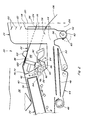
- FIGS. 1 , 2 , 3 , 4 , 5 , and 6 a self-propelled agricultural combine 20 is shown, including an on-board baler 22 operable for compacting crop residue and chaff into large square bales and discharging the bales, and dust suppression apparatus 24, constructed according to the present invention.
- Combine 20 includes harvesting apparatus 26 having a crop appropriate, e.g., corn or grain, header 28 constructed and operable in the well known manner for cutting crops from a field and gathering the cut crops; and a feeder 30 also constructed and operable in the well known manner for receiving the cut crops, initially compressing them into a continuous mat 32 ( FIG. 6 ), and conveying them to a threshing system 34 contained within a housing 36 of combine 20.
- a crop appropriate e.g., corn or grain
- header 28 constructed and operable in the well known manner for cutting crops from a field and gathering the cut crops
- a feeder 30 also constructed and operable in the well known manner for receiving the cut crops, initially compressing them into a continuous mat 32 ( FIG. 6 ), and conveying them to a threshing system 34 contained within a housing 36 of combine 20.
- Threshing system 34 also constructed and operable in the well known manner, includes apparatus configured and operable for separating larger elements of crop residue, also referred to generally as straw, and including stalks, cobs, stems, leaves, weeds and other larger plant matter, from the grain and chaff comprising smaller elements of crop residue, e.g., fragments of pods, leaves, cobs, husks, etc.
- threshing system 34 is depicted as a dual rotor system including two side by side generally cylindrical rotors 38 rotatable by suitable drive apparatus within perforated cylindrical concaves 40, respectively, for conveying the compressed crop mat in a helical manner through an annular gap therebetween, for threshing grain and smaller elements of crop residue or chaff, from the larger crop residue which will remain in mat 32.
- the larger crop residue still largely in the form of compressed mats 32, is then discharged from a discharge end 42 of threshing system 34 as a combined first flow, denoted by arrows A, from discharge ends of rotors 38.
- the dual rotors 38 are counterrotating, and discharge their mats 32 in a convergent manner which forms the flow A, although it should be noted that other threshing system configurations can be used with the present invention, to discharge this residue in different manners, e.g., as a single mat, more toward one side of the threshing system or the other, with equal utility for the purposes of the invention.
- the baler 22 can be incorporated into a wide variety of harvesters, including those with a single rotor threshing system, and those including a separation cylinder or cylinders such as found on newer hybrid combines.
- Second flow B will comprise the grain mixed with the smaller elements of crop residue or chaff. Flow B will fall through an interior cavity of housing 36, onto elements of a cleaning system 44 of the combine.
- Cleaning system 44 of combine 20 separates the chaff, e.g. fragments of seed pods, husks, etc., from the grain, using a rearwardly and upwardly directed flow of air, denoted by arrows D, from a forwardly located fan 46, directed through a lower sieve 48 and an upper sieve 50.
- flow B will fall variously onto upper sieve 50 and a grain pan forwardly thereof, and will be agitated by reciprocating movements of that pan and sieve in the well known manner.
- Sieve 50 has openings therethrough sized to allow passage of the grain and similarly sized elements of chaff therethrough, as denoted by arrows B1 in FIG.
- Sieve 48 has openings therethrough sized to allow passage of the grain therethrough, as denoted by arrows B2, but not larger elements of chaff, also referred to as tailings, which will be carried rearwardly, as denoted by arrows B3. Grain B2 will then be collected in the well known manner. Tailings B3 will typically be reprocessed, also in the well known manner.
- Chaff conveyor system 52 of the invention functions in cooperation with baler 22 and dust suppression apparatus 24 of the invention.
- Chaff conveyor system 52 includes a chaff collection conveyor 54 disposed adjacent a rear end of upper sieve 50, in position for receiving chaff flow C therefrom, as illustrated.
- chaff collection conveyor 54 has a width about equal to that of sieve 50, and is positioned rearwardly thereof at a lower end of an inclined chaff pan 56, extending rearwardly and downwardly from the rear edge of the sieve 50. This is also advantageous as it places conveyor 54 also below an upwardly extending duct 58 of dust suppression apparatus 24, for collecting any particles of chaff that fall from airborne suspension in that apparatus, as will be explained.
- Conveyor 54 includes a helical auger 60 supported for rotation in an upwardly open auger trough 62 and operable for conveying chaff therein to one end thereof, as denoted by arrows F in FIGS. 3 and 4 .
- Trough 62 can optionally have a door or removable bottom or side panel or door, to allow inspection and cleanout of accumulated crop residue, as denoted by dotted lines in FIG. 2 .
- This door can also be opened to allow the chaff to fall through conveyor 54, either onto the ground or an optional chaff spreader that can be positioned below conveyor 54, as discussed below.
- apparatus can be provided to allow covering conveyor 54 such that all or a portion of the chaff will bypass that conveyor, as will be also be discussed.
- Chaff conveyor system 52 includes a second chaff conveyor 64 which is also preferably a helical auger type conveyor, including a helical auger 66 supported for rotation within an upwardly and forwardly extending tube 68.
- Conveyor 64 is operable for conveying the chaff flow F upwardly and forwardly, to a location adjacent to the first location, e.g., the area where the crop residue A is discharged from threshing system 34 en route to baler 22.
- a bucket or other type of conveyor could be used.
- Chaff conveyor system 52 preferably includes a third chaff conveyor 70, which is disposed adjacent to or in the first location, between threshing system 34 and baler 22, and more preferably extending across that location, so as to be operable for conveying the chaff flow F to the crop residue flow A, and discharging the chaff generally evenly, or at a more central location, into flow A en route to baler 22.
- conveyor 70 preferably has a tubular or enclosed housing 72 containing an impeller for moving the chaff therethrough, which is preferably a helical auger 74. Conveyor 70 is shown at alternative locations in FIGS.
- housing 72 includes perforations or openings 76 for passage of chaff F therefrom for discharge into with crop residue flow A, so as to mix therewith as denoted by arrows AF, which openings can include, but are not limited to, partial circumferential slots or the like.
- auger 74 of conveyor 70 can include radially outwardly extending impeller elements 78 thereabout, e.g., rods or blades, which project outwardly through openings 76 and move in the direction of flow F, for facilitating free passage of the chaff through the openings, and also for facilitating flow and mixture of flows A and F into the mixed crop residue and chaff flow AF.
- impeller elements 78 thereabout, e.g., rods or blades, which project outwardly through openings 76 and move in the direction of flow F, for facilitating free passage of the chaff through the openings, and also for facilitating flow and mixture of flows A and F into the mixed crop residue and chaff flow AF.
- elements 78 also move in relation to a lower peripheral surface or grain pan 132 of a housing containing an inlet passage 84 of baler 22, which pan can be perforated as denoted by openings 134, to provide a supplemental threshing action, and to allow any remaining grain in flows F and A to be diverted to the cleaning system located below pan 132, as denoted by arrows in FIGS. 7 , 8 and 9 .
- an additional impeller or impellers such as one or both of impellers 80 and 82 can be provided as desired or required at suitable locations, to facilitate the agitation, mixing and flow of crop residue and chaff flow AF, and also supplemental threshing.
- impeller 82 In one exemplary embodiment ( FIGS. 1 and 2 ) only impeller 82 is used in cooperation with conveyor 70, and in other exemplary embodiments ( FIGS. 7 and 8 ) two impellers 80 and 82 are illustrated in association with conveyor 70. Additionally, either of impellers 80 and 82 can be configured as knives, or to include knives or blades, tines, or other projections, such as a well known rotor cutter type construction having multiple knives at skewed locations about a rotational axis of the cutter. Still further, as additional alternatives, a low speed rotary cutter with rigid tines, a low speed chopper with rotating blades, or a high speed chopper, could be used.
- Baler 22 itself is preferably a medium or large rectangular baler basically of known construction, such as described and disclosed in Naaktgeboren, U.S. Patent No. 4,525,991, issued July 2, 1985 .
- Baler 22 differs from known balers such as those of the referenced patent, by configuring inlet passage 84 as a duct which is generally U-shaped, having a first or downwardly extending first portion bounded on the lower end by pan 132 and configured and operable for receiving the flow F of crop residue already in at least a partially compressed state, e.g., and mixing the chaff therein as just described, instead of just an upwardly extending passage or duct for receiving a flow of straw or hay in a loose condition from the ground using various means such as rakes, rotary cutters or the like.
- baler 22 includes stuffer forks 90 operable in the well known manner to move into, and upwardly along, pre-compressing chamber 86, as denoted by arrow G, for raking and compressing the crop residue and chaff mix upwardly toward bale forming chamber 88.
- baler 22 of the present invention can comprise, without limitation, a wide variety of pre-compressing or feeding apparatus and systems, such as commercially available rotary systems and the like.
- Bale forming chamber 88 is an elongate passage of rectangular cross section, which can be adjusted to taper convergingly from an inlet end 96 toward a rear or outlet end 98 thereof.
- a plunger 100 extends into the inlet end and is reciprocatingly movable, e.g., about 30 to 60 times per minute, within chamber 88 toward outlet end 98 for compressing the crop residue and chaff into a rectangular bale 104 against a preceding bale 104 in the outlet end 98 of the chamber.
- a knotting mechanism 102 is operable for securing baling twine about the sections of the bale as they are completed, and a new bale is formed in abutting relation to the preceding bale, which is gradually pushed from the bale-forming chamber by the action of plunger 100.
- Suitable known representative knotting mechanisms are disclosed and described in Eylenbosch, U.S. Patent No. 7,600,470 B2, issued October 13, 2009 , as well as a variety of other patents.
- Baling twine can be stored on combine 20 at any convenient location, such as below cleaning system 44 or the like (not shown).
- a suitable ramp 106 can be provided for dropping the completed bales 104 onto the ground behind the combine 20, or onto a bale accumulator, wagon or other receiver (not shown) towed thereby.
- Combine 20 includes typical propulsion means including an engine 108 connected in driving communication with drive wheels 110 in the well known manner, as illustrated by combines available for sale from a variety of manufacturers.
- Harvesting apparatus 26, threshing system 34 and cleaning system 44 will be driven by engine 108 via a conventional driveline, also in the well-known manner.
- Conveyors 54, 64 and 70 can be operatively driven by engine 108 in any suitable manner, such as by using fluid motors 112, belts, chains, or the like.
- Baler 22 will be suitably powered by engine 108 also, via fluid or electric motors, belts, and/or chains.
- Apparatus 24 preferably includes an inlet plenum 114 across the rear end of housing 36 and incorporating inlet passage 84, configured and positioned for receiving flows of air D, and a pair of upwardly extending cyclones or ducts 116 on opposite sides of baler 22, respectively.
- Ducts 116 extend upwardly to connect with upper ends 118 of downwardly extending diffusers or ducts 120 in a generally overall U-shape, and a plurality of baffles 122 are disposed at or in the vicinity of this juncture.
- An optional supplemental blower or blowers can also be provided in connection with the upwardly extending ducts 116, to direct and boost the air and dust flow upwardly therethrough, if desired or required for a particular application, as denoted by blowers 150 in FIG. 4 .
- Baffles 122 are oriented to extend downwardly at an incline to horizontal in the direction of flows D, and are located adjacent to a perforated upstanding wall 124 of downwardly extending duct 120, for directing or deflecting at least a substantial portion of the particles and dust which reaches or enters the downwardly extending duct, downwardly therethrough, as denoted by arrows D1, and so as to allow the air flow D that enters the downwardly extending duct to flow outwardly therefrom and diffuse through perforated upstanding wall 124.
- the upward extent of ducts 116 and presence of baffles 122 can also serve to cause the larger particles of chaff and dust to fall out of suspension in the air so as to drop into chaff collection conveyor 54 so as to be baled.
- Perforated wall 124 can include a variety of configurations of perforations, such as, but not limited to, a graduated array of progressively larger and closer together openings or holes, which are configured to achieve a low static air pressure and particle velocity in the lower region of duct 120.
- a first array of smaller slots 126 can be provided in an upper region of wall 124, and a second array of larger slots 128 can be provided in a lower region, to achieve the desired air diffusion and low pressure particle discharge.
- dust suppression apparatus 24 of the invention most of the air flow exiting is mainly clean, including being largely free of weed seeds, so as to provide good weed control.
- the combine is then more environmentally friendly than current models because it is injecting the chaff into the bale and separates the dust from the air at the outlet and lets the dust settle down in a large venting conduit, e.g., duct 120.
- an optional skirt can be added about the bottom of apparatus 24, to further keep the dust down.
- baler 22 of combine 20 is shown in association with aspects of threshing system 34 and chaff conveyor system 52.
- threshing system 34 is illustrated alternatively in solid and dotted lines as a single rotor system (taller), and as a dual rotor system (shorter), respectively.
- third chaff conveyor 70 is disposed in inlet passage 84 of baler 22 above a rotary impeller 82, and is operable for discharging a flow of chaff F into the flow of crop residue A discharged by threshing system 34 to form a mixed flow AF as described above.
- Impeller 82 is again configured as a rotary cutter type impeller having radially outwardly extending blades thereabout.
- a row of stationary knives 136 is disposed in connection with pan 132 so as to extend upwardly between the blades of rotating impeller 82, for chopping the flow AF as it flows through passage 84 en route to the bale forming chamber.
- Stationary knives 136 are maintained in this position by a knife support mechanism 138, operable using a lever 140 thereof as illustrated by an arrow, for optionally fully or partially retracting the knives 136, such that the flow AF can remain unchopped, if desired.
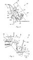
- FIG. 11 an alternative configuration of chaff collection conveyor 54 of chaff conveyor system 52 of combine 20 is shown, including a lower opening, and a representative chaff spreader 142 disposed therebelow.
- chaff flow C from cleaning system 44 will pass through conveyor 54 to spreader 142, so as to be spread over the ground by rotary operation thereof, while air flow D from the cleaning system will flow upwardly to dust suppression apparatus 24.
- a horizontal rotary spreader is illustrated, it should be noted that this configuration can alternatively use a variety of spreaders, such as a vertical spreader or the like, with equal utility.
- opening 140 can comprise a single large opening, a slotted opening, or a plurality of other smaller openings, as desired or required for a particular application.
- FIGS. 12 and 13 still another alternative configuration of conveyor 54 of chaff conveyor system 52 is illustrated, here including a diverter door system 144 configurable in a first manner as shown in FIG. 12 , for allowing chaff flow C from cleaning system 44 of combine 20 to enter conveyor 54, and air flow D to enter dust suppression system 24.
- door system 144 is configurable to open a rear opening 146 and close off conveyor 54 to prevent entry of chaff into that conveyor, while serving as a surface for carrying the chaff rearwardly through rear opening 146.
- an upper door 148 of system 144 is configurable to close off dust suppression system 24, such that the chaff flow C and air flow D will both pass through rear opening 146, to an optional spreader 142 mounted rearwardly of conveyor 54, such that the chaff will be spread by operation of the spreader, or, if the spreader is not present or used, discharged onto the ground.
- header 28 can include a chopper or choppers on a lower portion thereof, configured and operable for receiving, chopping and returning a portion of the crop residue onto the ground, to provide nutrients and fertilizer, and to fight soil erosion.
Landscapes
- Life Sciences & Earth Sciences (AREA)
- Environmental Sciences (AREA)
- Threshing Machine Elements (AREA)
- Combines (AREA)
Applications Claiming Priority (2)
| Application Number | Priority Date | Filing Date | Title |
|---|---|---|---|
| US21285709P | 2009-04-16 | 2009-04-16 | |
| US12/652,389 US8313362B2 (en) | 2009-04-16 | 2010-01-05 | Agricultural combine with on-board baler and dust suppression capability |
Publications (3)
| Publication Number | Publication Date |
|---|---|
| EP2241174A2 true EP2241174A2 (de) | 2010-10-20 |
| EP2241174A3 EP2241174A3 (de) | 2017-09-20 |
| EP2241174B1 EP2241174B1 (de) | 2019-05-08 |
Family
ID=42342814
Family Applications (1)
| Application Number | Title | Priority Date | Filing Date |
|---|---|---|---|
| EP10158952.1A Active EP2241174B1 (de) | 2009-04-16 | 2010-04-01 | Mähdrescher mit bordeigener Ballenpresse und Staubunterdrückungsfunktion |
Country Status (2)
| Country | Link |
|---|---|
| US (1) | US8313362B2 (de) |
| EP (1) | EP2241174B1 (de) |
Cited By (5)
| Publication number | Priority date | Publication date | Assignee | Title |
|---|---|---|---|---|
| EP2522210A1 (de) * | 2011-05-12 | 2012-11-14 | CLAAS Selbstfahrende Erntemaschinen GmbH | Mähdrescher |
| WO2016004631A1 (zh) * | 2014-07-07 | 2016-01-14 | 江苏大学 | 一种切纵流式谷物联合收获打捆复式作业机 |
| US9253946B2 (en) | 2011-10-05 | 2016-02-09 | James E. Straeter | Bale accumulator system |
| US20210315163A1 (en) * | 2018-09-07 | 2021-10-14 | Roy BREWIN | Crop dust separation system |
| US20220007586A1 (en) * | 2020-07-09 | 2022-01-13 | Ty E. Stukenholtz | Agricultural chaff collector |
Families Citing this family (26)
| Publication number | Priority date | Publication date | Assignee | Title |
|---|---|---|---|---|
| US20100326037A1 (en) * | 2009-06-24 | 2010-12-30 | Dillon Ben N | Crop Residue Baler Integrated with Harvester, Method for Baling Crop Residue, and Resulting Trapezoidal Crop Residue Bale |
| US8056313B1 (en) * | 2009-06-26 | 2011-11-15 | Exact Corp. | Mobile machinery having a dust suppression system |
| US8464508B2 (en) | 2009-07-31 | 2013-06-18 | Agco Corporation | Biomass baler |
| US8490375B2 (en) * | 2009-07-31 | 2013-07-23 | Agco Corporation | Baler collector for collecting biomass from a combine harvester |
| US8443580B2 (en) | 2009-07-31 | 2013-05-21 | Agco Corporation | Baler pickup for collecting biomass from a combine harvester |
| US20110023439A1 (en) * | 2009-07-31 | 2011-02-03 | Agco Corporation | Biomass Deflector |
| US8062109B1 (en) * | 2010-08-27 | 2011-11-22 | Deere & Company | Dust suppressor for combine harvester feederhouse |
| US8251788B2 (en) * | 2010-10-30 | 2012-08-28 | Stukenholtz Ty E | Agricultural material separator |
| US20120124956A1 (en) * | 2010-11-18 | 2012-05-24 | Oakes Scott D | Method and Apparatus for Harvesting a Grain Crop |
| US8635844B1 (en) * | 2011-03-29 | 2014-01-28 | Hbi Branded Apparel Enterprises, Llc | Method for harvesting bast plants |
| US8585475B2 (en) | 2011-04-19 | 2013-11-19 | Cnh America Llc | Crop residue distribution apparatus and system with cooperatively movable deflector door and spreader assembly |
| US8733241B2 (en) | 2012-05-15 | 2014-05-27 | Cnh Industrial Canada, Ltd. | Continuous round baler chambers and conveyor system |
| US8596396B1 (en) * | 2012-08-15 | 2013-12-03 | Cnh America Llc | Air intake configuration for an agricultural harvesting machine |
| US9084394B2 (en) | 2013-02-22 | 2015-07-21 | CNH Industrial Canada, LTD | Continuous crop accumulator for agricultural harvesters |
| US9955628B2 (en) * | 2015-09-25 | 2018-05-01 | Deere & Company | Reversible drive system for an agricultural machine |
| GB201604781D0 (en) * | 2016-03-22 | 2016-05-04 | Agco Int Gmbh | Combine harvester grain cleaning system |
| USD794086S1 (en) | 2016-05-19 | 2017-08-08 | Forage Innovations B.V. | Self-propelled agricultural machine |
| CN106358605B (zh) * | 2016-08-29 | 2019-04-02 | 江苏大学 | 高效能履带式捡拾打捆机及其草捆自动堆垛系统 |
| US10314232B2 (en) | 2017-06-21 | 2019-06-11 | Cnh Industrial America Llc | System and method for destroying seeds in crop residue prior to discharge from agricultural harvester |
| US10806080B2 (en) | 2017-08-25 | 2020-10-20 | Flory Industries | Tree fruit or nut harvester to minimize machine passes in the orchard |
| CN108617268B (zh) * | 2018-04-19 | 2020-12-01 | 徐州工程学院 | 玉米秸秆处理装置及玉米秸秆处理的方法 |
| US20200019968A1 (en) | 2018-07-11 | 2020-01-16 | Capital One Services, Llc | System and method for authenticating transactions from a mobile device |
| US11395984B2 (en) | 2019-05-24 | 2022-07-26 | Flory Industries | Dust control system and related methods |
| WO2021163195A1 (en) * | 2020-02-12 | 2021-08-19 | Cnh Industrial Canada, Ltd. | Accumulating system for an agricultural system |
| US12543624B2 (en) | 2021-10-05 | 2026-02-10 | Tribine Industries Llc | Seedbed preparation method and mechanism |
| US12329048B2 (en) | 2023-08-15 | 2025-06-17 | Tribine Industries, LLC | Articulated combine having rear module with seedbed preparation mechanism |
Citations (6)
| Publication number | Priority date | Publication date | Assignee | Title |
|---|---|---|---|---|
| US2030031A (en) | 1933-05-24 | 1936-02-04 | Innes Mfg Company | Baling apparatus |
| US4525991A (en) | 1984-01-09 | 1985-07-02 | Sperry Corporation | Baler feeder mechanism |
| JP2003180119A (ja) | 2001-12-17 | 2003-07-02 | Yanmar Agricult Equip Co Ltd | コンバイン |
| US20070191081A1 (en) | 2001-12-18 | 2007-08-16 | Shields Graham M | Baling Apparatus |
| JP2007228943A (ja) | 2006-03-03 | 2007-09-13 | Iseki & Co Ltd | ロールベーラ付コンバイン |
| US7600470B2 (en) | 2007-08-14 | 2009-10-13 | Cnh America Llc | Square baler for forming sliced bales |
Family Cites Families (38)
| Publication number | Priority date | Publication date | Assignee | Title |
|---|---|---|---|---|
| US1314437A (en) * | 1919-08-26 | Portable combined cotton picking | ||
| US1350847A (en) * | 1917-06-11 | 1920-08-24 | John T Smith | Attachment for threshing-machines |
| US1368140A (en) * | 1920-02-07 | 1921-02-08 | Hagen Carl Edward | Dust-remover for threshing-machines |
| US1624126A (en) * | 1922-06-21 | 1927-04-12 | Wallenberg Axel Edva Henrikson | Thrashing machine |
| US1844344A (en) * | 1929-01-22 | 1932-02-09 | Alfred J Breeden | Buncher attachment for combined harvesters and threshers |
| US1980027A (en) * | 1933-07-05 | 1934-11-06 | Charles R Adams | Straw gathering attachment for harvesters |
| US2158729A (en) * | 1937-06-22 | 1939-05-16 | Glen C Peterson | Straw bundler |
| BE554331A (de) * | 1956-01-19 | |||
| US3242658A (en) * | 1964-03-24 | 1966-03-29 | Morales Richard | Lawn mower with baler for clippings |
| US4178944A (en) * | 1977-10-11 | 1979-12-18 | Allis-Chalmers Corporation | Tailings return for an axial flow combine |
| US5098341A (en) * | 1990-11-26 | 1992-03-24 | Kuchar George J | Air diverter for chaff removal in a combine |
| JPH04210518A (ja) | 1990-12-01 | 1992-07-31 | Kubota Corp | ハーベスタの除塵装置 |
| JPH04222520A (ja) | 1990-12-21 | 1992-08-12 | Kubota Corp | ハーベスタの除塵構造 |
| US5255501A (en) * | 1992-02-28 | 1993-10-26 | Mcwilliams Alexander | Baler for forming cylindrical bales |
| WO1994024845A2 (de) * | 1993-05-05 | 1994-11-10 | Same S.P.A. | Landwirtschaftliche maschine, insbesondere selbstfahrende grossballenpresse |
| DE4326849A1 (de) * | 1993-08-10 | 1995-02-16 | Franz Haimer | Verfahren und Vorrichtung zum Pelletieren von Biomasse |
| US6036600A (en) * | 1998-06-02 | 2000-03-14 | Kruckman; Harold D. | Combine dust eliminator |
| DE19912372C1 (de) * | 1999-03-19 | 2000-11-09 | Case Harvesting Sys Gmbh | Vorrichtung zur Messung des Kornanteiles in einer Überkehr eines Mähdreschers |
| US6263650B1 (en) * | 1999-09-23 | 2001-07-24 | Deere & Company | Cotton harvester with accumulator |
| US6591145B1 (en) * | 2000-09-21 | 2003-07-08 | Bechtel Bwxt Idaho, Llc | Systems and methods for autonomously controlling agricultural machinery |
| GB2375032A (en) * | 2001-04-30 | 2002-11-06 | Ford New Holland Nv | Elevator for an agricultural harvesting machine |
| DE10147733A1 (de) * | 2001-09-27 | 2003-04-10 | Claas Selbstfahr Erntemasch | Verfahren und Vorrichtung zur Ermittlung einer Erntemaschineneinstellung |
| US6729951B2 (en) * | 2002-03-28 | 2004-05-04 | Bechtel Bwxt Idaho, Llc | Method and apparatus for selectively harvesting multiple components of a plant material |
| US7370573B1 (en) * | 2002-06-27 | 2008-05-13 | Weldon Leroy Lackey | Method and apparatus for forming modules from harvested crops |
| US6651417B1 (en) * | 2002-06-27 | 2003-11-25 | Weldon Leroy Lackey | Method and apparatus for forming modules from harvested crops |
| US7025673B2 (en) * | 2003-01-10 | 2006-04-11 | Cnh America Llc | Tailings conveyor system |
| US6761630B1 (en) * | 2003-02-10 | 2004-07-13 | Case, Llc | Method of operation of a sieve adjustment control system for an agricultural combine |
| GB0408931D0 (en) * | 2004-04-22 | 2004-05-26 | Cnh Belgium Nv | Method for operating a grain cleaning system in a combine harvester |
| EA200500455A1 (ru) * | 2005-01-11 | 2006-04-28 | Петр Иванович Чуксин | Способ уборки зерновых культур, зерноуборочный комбайн и его узлы |
| US20090019826A1 (en) * | 2007-07-03 | 2009-01-22 | James Edward Rigney | Method and apparatus for processing plant materials for bio-fuel production |
| US7934982B2 (en) * | 2007-10-31 | 2011-05-03 | Deere & Company | Tailings rethresher mechanical delivery to return pan |
| US7762877B2 (en) * | 2007-11-29 | 2010-07-27 | Deere & Company | Tailing re-thresher rasp bar and rotor housing |
| US20100330337A1 (en) * | 2009-06-24 | 2010-12-30 | Dillon Ben N | Crop Residue Baler Integrated With Harvester, Method for Baling Crop Residue, and Resulting Trapezoidal Crop Residue Bale |
| US20100326037A1 (en) * | 2009-06-24 | 2010-12-30 | Dillon Ben N | Crop Residue Baler Integrated with Harvester, Method for Baling Crop Residue, and Resulting Trapezoidal Crop Residue Bale |
| US20100326292A1 (en) * | 2009-06-24 | 2010-12-30 | Dillon Ben N | Crop Residue Baler Integrated with Harvester and Method for Baling Crop Residue |
| US8464508B2 (en) * | 2009-07-31 | 2013-06-18 | Agco Corporation | Biomass baler |
| US20110023440A1 (en) * | 2009-07-31 | 2011-02-03 | Agco Corporation | Method For Projecting Biomass From A Combine Harvester |
| US8250843B2 (en) * | 2010-03-31 | 2012-08-28 | Weyerhaeuser Nr Company | Combination biomass harvester and baler |
-
2010
- 2010-01-05 US US12/652,389 patent/US8313362B2/en not_active Expired - Fee Related
- 2010-04-01 EP EP10158952.1A patent/EP2241174B1/de active Active
Patent Citations (6)
| Publication number | Priority date | Publication date | Assignee | Title |
|---|---|---|---|---|
| US2030031A (en) | 1933-05-24 | 1936-02-04 | Innes Mfg Company | Baling apparatus |
| US4525991A (en) | 1984-01-09 | 1985-07-02 | Sperry Corporation | Baler feeder mechanism |
| JP2003180119A (ja) | 2001-12-17 | 2003-07-02 | Yanmar Agricult Equip Co Ltd | コンバイン |
| US20070191081A1 (en) | 2001-12-18 | 2007-08-16 | Shields Graham M | Baling Apparatus |
| JP2007228943A (ja) | 2006-03-03 | 2007-09-13 | Iseki & Co Ltd | ロールベーラ付コンバイン |
| US7600470B2 (en) | 2007-08-14 | 2009-10-13 | Cnh America Llc | Square baler for forming sliced bales |
Cited By (8)
| Publication number | Priority date | Publication date | Assignee | Title |
|---|---|---|---|---|
| EP2522210A1 (de) * | 2011-05-12 | 2012-11-14 | CLAAS Selbstfahrende Erntemaschinen GmbH | Mähdrescher |
| US9253946B2 (en) | 2011-10-05 | 2016-02-09 | James E. Straeter | Bale accumulator system |
| WO2016004631A1 (zh) * | 2014-07-07 | 2016-01-14 | 江苏大学 | 一种切纵流式谷物联合收获打捆复式作业机 |
| US9949433B2 (en) | 2014-07-07 | 2018-04-24 | Jiangsu University | Cutting longitudinal swaths grain harvesting and baling combine |
| US20210315163A1 (en) * | 2018-09-07 | 2021-10-14 | Roy BREWIN | Crop dust separation system |
| US12096721B2 (en) * | 2018-09-07 | 2024-09-24 | Roy BREWIN | Crop dust separation system |
| US20220007586A1 (en) * | 2020-07-09 | 2022-01-13 | Ty E. Stukenholtz | Agricultural chaff collector |
| US11751509B2 (en) * | 2020-07-09 | 2023-09-12 | Farmmax, Llc | Agricultural chaff collector |
Also Published As
| Publication number | Publication date |
|---|---|
| EP2241174B1 (de) | 2019-05-08 |
| US8313362B2 (en) | 2012-11-20 |
| US20100267432A1 (en) | 2010-10-21 |
| EP2241174A3 (de) | 2017-09-20 |
Similar Documents
| Publication | Publication Date | Title |
|---|---|---|
| EP2241174B1 (de) | Mähdrescher mit bordeigener Ballenpresse und Staubunterdrückungsfunktion | |
| EP1529434B1 (de) | System zum Ausstossen von Ernteresten aus einem Mähdrescher | |
| BE1019133A3 (nl) | Een maaidorser. | |
| US9491909B2 (en) | Continuous round baler chambers and conveyor system | |
| EP2482630B1 (de) | Restetrenn- und -fördersystem für biomasse | |
| CA2644959C (en) | Separating cobs from grain in a corn harvester | |
| US5873226A (en) | McLeod harvesting system and method | |
| WO2016004631A1 (zh) | 一种切纵流式谷物联合收获打捆复式作业机 | |
| CN216982604U (zh) | 一种自走轮式谷物联合收割机 | |
| WO2006074667A2 (en) | Method of grain harvesting, combine harvester and harvester's units | |
| US5794423A (en) | Mobile harvester for chaff, grain, grain leavings and weed seeds | |
| US5795222A (en) | McLeod yard plant | |
| US11751509B2 (en) | Agricultural chaff collector | |
| US20090000263A1 (en) | Harvesting and Threshing System | |
| EP3087818A1 (de) | Streuanordnung für eine landwirtschaftliche erntemaschine | |
| US20200404851A1 (en) | Combine with a pre-thresher | |
| RU2556071C2 (ru) | Способ комбайновой уборки обмолотом зерна на корню и комбайн с прицепом для сбора незерновой части очесанного вороха | |
| EP4714247A1 (de) | Rückstandsbehandlungssystem für mähdrescher | |
| AU646580B2 (en) | Clover seed harvester | |
| AU2011265350A1 (en) | A Method and System for Controlling Weed Growth | |
| CS235491B1 (cs) | Zařízení pro sklizeň plev a úhrabků u sklízečích mlátiček |
Legal Events
| Date | Code | Title | Description |
|---|---|---|---|
| PUAI | Public reference made under article 153(3) epc to a published international application that has entered the european phase |
Free format text: ORIGINAL CODE: 0009012 |
|
| AK | Designated contracting states |
Kind code of ref document: A2 Designated state(s): AT BE BG CH CY CZ DE DK EE ES FI FR GB GR HR HU IE IS IT LI LT LU LV MC MK MT NL NO PL PT RO SE SI SK SM TR |
|
| AX | Request for extension of the european patent |
Extension state: AL BA ME RS |
|
| RAP1 | Party data changed (applicant data changed or rights of an application transferred) |
Owner name: CNH INDUSTRIAL BELGIUM NV |
|
| PUAL | Search report despatched |
Free format text: ORIGINAL CODE: 0009013 |
|
| AK | Designated contracting states |
Kind code of ref document: A3 Designated state(s): AT BE BG CH CY CZ DE DK EE ES FI FR GB GR HR HU IE IS IT LI LT LU LV MC MK MT NL NO PL PT RO SE SI SK SM TR |
|
| AX | Request for extension of the european patent |
Extension state: AL BA ME RS |
|
| RIC1 | Information provided on ipc code assigned before grant |
Ipc: A01D 43/00 20060101ALI20170814BHEP Ipc: A01D 41/12 20060101AFI20170814BHEP Ipc: A01F 12/54 20060101ALI20170814BHEP Ipc: A01F 15/04 20060101ALI20170814BHEP Ipc: A01F 12/44 20060101ALI20170814BHEP |
|
| STAA | Information on the status of an ep patent application or granted ep patent |
Free format text: STATUS: REQUEST FOR EXAMINATION WAS MADE |
|
| 17P | Request for examination filed |
Effective date: 20180320 |
|
| RBV | Designated contracting states (corrected) |
Designated state(s): AT BE BG CH CY CZ DE DK EE ES FI FR GB GR HR HU IE IS IT LI LT LU LV MC MK MT NL NO PL PT RO SE SI SK SM TR |
|
| GRAP | Despatch of communication of intention to grant a patent |
Free format text: ORIGINAL CODE: EPIDOSNIGR1 |
|
| STAA | Information on the status of an ep patent application or granted ep patent |
Free format text: STATUS: GRANT OF PATENT IS INTENDED |
|
| INTG | Intention to grant announced |
Effective date: 20181204 |
|
| GRAS | Grant fee paid |
Free format text: ORIGINAL CODE: EPIDOSNIGR3 |
|
| GRAA | (expected) grant |
Free format text: ORIGINAL CODE: 0009210 |
|
| STAA | Information on the status of an ep patent application or granted ep patent |
Free format text: STATUS: THE PATENT HAS BEEN GRANTED |
|
| AK | Designated contracting states |
Kind code of ref document: B1 Designated state(s): AT BE BG CH CY CZ DE DK EE ES FI FR GB GR HR HU IE IS IT LI LT LU LV MC MK MT NL NO PL PT RO SE SI SK SM TR |
|
| REG | Reference to a national code |
Ref country code: GB Ref legal event code: FG4D |
|
| REG | Reference to a national code |
Ref country code: CH Ref legal event code: EP Ref country code: AT Ref legal event code: REF Ref document number: 1128699 Country of ref document: AT Kind code of ref document: T Effective date: 20190515 |
|
| REG | Reference to a national code |
Ref country code: DE Ref legal event code: R096 Ref document number: 602010058692 Country of ref document: DE Ref country code: IE Ref legal event code: FG4D |
|
| REG | Reference to a national code |
Ref country code: NL Ref legal event code: MP Effective date: 20190508 |
|
| REG | Reference to a national code |
Ref country code: LT Ref legal event code: MG4D |
|
| PG25 | Lapsed in a contracting state [announced via postgrant information from national office to epo] |
Ref country code: LT Free format text: LAPSE BECAUSE OF FAILURE TO SUBMIT A TRANSLATION OF THE DESCRIPTION OR TO PAY THE FEE WITHIN THE PRESCRIBED TIME-LIMIT Effective date: 20190508 Ref country code: ES Free format text: LAPSE BECAUSE OF FAILURE TO SUBMIT A TRANSLATION OF THE DESCRIPTION OR TO PAY THE FEE WITHIN THE PRESCRIBED TIME-LIMIT Effective date: 20190508 Ref country code: SE Free format text: LAPSE BECAUSE OF FAILURE TO SUBMIT A TRANSLATION OF THE DESCRIPTION OR TO PAY THE FEE WITHIN THE PRESCRIBED TIME-LIMIT Effective date: 20190508 Ref country code: HR Free format text: LAPSE BECAUSE OF FAILURE TO SUBMIT A TRANSLATION OF THE DESCRIPTION OR TO PAY THE FEE WITHIN THE PRESCRIBED TIME-LIMIT Effective date: 20190508 Ref country code: NL Free format text: LAPSE BECAUSE OF FAILURE TO SUBMIT A TRANSLATION OF THE DESCRIPTION OR TO PAY THE FEE WITHIN THE PRESCRIBED TIME-LIMIT Effective date: 20190508 Ref country code: NO Free format text: LAPSE BECAUSE OF FAILURE TO SUBMIT A TRANSLATION OF THE DESCRIPTION OR TO PAY THE FEE WITHIN THE PRESCRIBED TIME-LIMIT Effective date: 20190808 Ref country code: FI Free format text: LAPSE BECAUSE OF FAILURE TO SUBMIT A TRANSLATION OF THE DESCRIPTION OR TO PAY THE FEE WITHIN THE PRESCRIBED TIME-LIMIT Effective date: 20190508 Ref country code: PT Free format text: LAPSE BECAUSE OF FAILURE TO SUBMIT A TRANSLATION OF THE DESCRIPTION OR TO PAY THE FEE WITHIN THE PRESCRIBED TIME-LIMIT Effective date: 20190908 |
|
| PG25 | Lapsed in a contracting state [announced via postgrant information from national office to epo] |
Ref country code: LV Free format text: LAPSE BECAUSE OF FAILURE TO SUBMIT A TRANSLATION OF THE DESCRIPTION OR TO PAY THE FEE WITHIN THE PRESCRIBED TIME-LIMIT Effective date: 20190508 Ref country code: GR Free format text: LAPSE BECAUSE OF FAILURE TO SUBMIT A TRANSLATION OF THE DESCRIPTION OR TO PAY THE FEE WITHIN THE PRESCRIBED TIME-LIMIT Effective date: 20190809 Ref country code: BG Free format text: LAPSE BECAUSE OF FAILURE TO SUBMIT A TRANSLATION OF THE DESCRIPTION OR TO PAY THE FEE WITHIN THE PRESCRIBED TIME-LIMIT Effective date: 20190808 |
|
| REG | Reference to a national code |
Ref country code: AT Ref legal event code: MK05 Ref document number: 1128699 Country of ref document: AT Kind code of ref document: T Effective date: 20190508 |
|
| PG25 | Lapsed in a contracting state [announced via postgrant information from national office to epo] |
Ref country code: RO Free format text: LAPSE BECAUSE OF FAILURE TO SUBMIT A TRANSLATION OF THE DESCRIPTION OR TO PAY THE FEE WITHIN THE PRESCRIBED TIME-LIMIT Effective date: 20190508 Ref country code: CZ Free format text: LAPSE BECAUSE OF FAILURE TO SUBMIT A TRANSLATION OF THE DESCRIPTION OR TO PAY THE FEE WITHIN THE PRESCRIBED TIME-LIMIT Effective date: 20190508 Ref country code: SK Free format text: LAPSE BECAUSE OF FAILURE TO SUBMIT A TRANSLATION OF THE DESCRIPTION OR TO PAY THE FEE WITHIN THE PRESCRIBED TIME-LIMIT Effective date: 20190508 Ref country code: DK Free format text: LAPSE BECAUSE OF FAILURE TO SUBMIT A TRANSLATION OF THE DESCRIPTION OR TO PAY THE FEE WITHIN THE PRESCRIBED TIME-LIMIT Effective date: 20190508 Ref country code: EE Free format text: LAPSE BECAUSE OF FAILURE TO SUBMIT A TRANSLATION OF THE DESCRIPTION OR TO PAY THE FEE WITHIN THE PRESCRIBED TIME-LIMIT Effective date: 20190508 Ref country code: AT Free format text: LAPSE BECAUSE OF FAILURE TO SUBMIT A TRANSLATION OF THE DESCRIPTION OR TO PAY THE FEE WITHIN THE PRESCRIBED TIME-LIMIT Effective date: 20190508 |
|
| REG | Reference to a national code |
Ref country code: DE Ref legal event code: R097 Ref document number: 602010058692 Country of ref document: DE |
|
| PG25 | Lapsed in a contracting state [announced via postgrant information from national office to epo] |
Ref country code: SM Free format text: LAPSE BECAUSE OF FAILURE TO SUBMIT A TRANSLATION OF THE DESCRIPTION OR TO PAY THE FEE WITHIN THE PRESCRIBED TIME-LIMIT Effective date: 20190508 Ref country code: IT Free format text: LAPSE BECAUSE OF FAILURE TO SUBMIT A TRANSLATION OF THE DESCRIPTION OR TO PAY THE FEE WITHIN THE PRESCRIBED TIME-LIMIT Effective date: 20190508 |
|
| PLBE | No opposition filed within time limit |
Free format text: ORIGINAL CODE: 0009261 |
|
| STAA | Information on the status of an ep patent application or granted ep patent |
Free format text: STATUS: NO OPPOSITION FILED WITHIN TIME LIMIT |
|
| PG25 | Lapsed in a contracting state [announced via postgrant information from national office to epo] |
Ref country code: TR Free format text: LAPSE BECAUSE OF FAILURE TO SUBMIT A TRANSLATION OF THE DESCRIPTION OR TO PAY THE FEE WITHIN THE PRESCRIBED TIME-LIMIT Effective date: 20190508 |
|
| 26N | No opposition filed |
Effective date: 20200211 |
|
| PG25 | Lapsed in a contracting state [announced via postgrant information from national office to epo] |
Ref country code: PL Free format text: LAPSE BECAUSE OF FAILURE TO SUBMIT A TRANSLATION OF THE DESCRIPTION OR TO PAY THE FEE WITHIN THE PRESCRIBED TIME-LIMIT Effective date: 20190508 |
|
| PG25 | Lapsed in a contracting state [announced via postgrant information from national office to epo] |
Ref country code: SI Free format text: LAPSE BECAUSE OF FAILURE TO SUBMIT A TRANSLATION OF THE DESCRIPTION OR TO PAY THE FEE WITHIN THE PRESCRIBED TIME-LIMIT Effective date: 20190508 |
|
| PG25 | Lapsed in a contracting state [announced via postgrant information from national office to epo] |
Ref country code: MC Free format text: LAPSE BECAUSE OF FAILURE TO SUBMIT A TRANSLATION OF THE DESCRIPTION OR TO PAY THE FEE WITHIN THE PRESCRIBED TIME-LIMIT Effective date: 20190508 |
|
| REG | Reference to a national code |
Ref country code: CH Ref legal event code: PL |
|
| PG25 | Lapsed in a contracting state [announced via postgrant information from national office to epo] |
Ref country code: LU Free format text: LAPSE BECAUSE OF NON-PAYMENT OF DUE FEES Effective date: 20200401 Ref country code: CH Free format text: LAPSE BECAUSE OF NON-PAYMENT OF DUE FEES Effective date: 20200430 Ref country code: LI Free format text: LAPSE BECAUSE OF NON-PAYMENT OF DUE FEES Effective date: 20200430 |
|
| REG | Reference to a national code |
Ref country code: BE Ref legal event code: MM Effective date: 20200430 |
|
| PG25 | Lapsed in a contracting state [announced via postgrant information from national office to epo] |
Ref country code: BE Free format text: LAPSE BECAUSE OF NON-PAYMENT OF DUE FEES Effective date: 20200430 |
|
| GBPC | Gb: european patent ceased through non-payment of renewal fee |
Effective date: 20200401 |
|
| PG25 | Lapsed in a contracting state [announced via postgrant information from national office to epo] |
Ref country code: IE Free format text: LAPSE BECAUSE OF NON-PAYMENT OF DUE FEES Effective date: 20200401 Ref country code: GB Free format text: LAPSE BECAUSE OF NON-PAYMENT OF DUE FEES Effective date: 20200401 |
|
| PG25 | Lapsed in a contracting state [announced via postgrant information from national office to epo] |
Ref country code: MT Free format text: LAPSE BECAUSE OF FAILURE TO SUBMIT A TRANSLATION OF THE DESCRIPTION OR TO PAY THE FEE WITHIN THE PRESCRIBED TIME-LIMIT Effective date: 20190508 Ref country code: CY Free format text: LAPSE BECAUSE OF FAILURE TO SUBMIT A TRANSLATION OF THE DESCRIPTION OR TO PAY THE FEE WITHIN THE PRESCRIBED TIME-LIMIT Effective date: 20190508 |
|
| PG25 | Lapsed in a contracting state [announced via postgrant information from national office to epo] |
Ref country code: MK Free format text: LAPSE BECAUSE OF FAILURE TO SUBMIT A TRANSLATION OF THE DESCRIPTION OR TO PAY THE FEE WITHIN THE PRESCRIBED TIME-LIMIT Effective date: 20190508 Ref country code: IS Free format text: LAPSE BECAUSE OF FAILURE TO SUBMIT A TRANSLATION OF THE DESCRIPTION OR TO PAY THE FEE WITHIN THE PRESCRIBED TIME-LIMIT Effective date: 20190908 |
|
| PGFP | Annual fee paid to national office [announced via postgrant information from national office to epo] |
Ref country code: FR Payment date: 20220425 Year of fee payment: 13 |
|
| PG25 | Lapsed in a contracting state [announced via postgrant information from national office to epo] |
Ref country code: FR Free format text: LAPSE BECAUSE OF NON-PAYMENT OF DUE FEES Effective date: 20230430 |
|
| PGFP | Annual fee paid to national office [announced via postgrant information from national office to epo] |
Ref country code: DE Payment date: 20240425 Year of fee payment: 15 |
|
| REG | Reference to a national code |
Ref country code: DE Ref legal event code: R119 Ref document number: 602010058692 Country of ref document: DE |
|
| PG25 | Lapsed in a contracting state [announced via postgrant information from national office to epo] |
Ref country code: DE Free format text: LAPSE BECAUSE OF NON-PAYMENT OF DUE FEES Effective date: 20251104 |