EP2241062B1 - Kommunikationssystem und -verfahren mit gruppenmastern zur seriellen datenübertragung in der automatisierungstechnik - Google Patents
Kommunikationssystem und -verfahren mit gruppenmastern zur seriellen datenübertragung in der automatisierungstechnik Download PDFInfo
- Publication number
- EP2241062B1 EP2241062B1 EP08707581.8A EP08707581A EP2241062B1 EP 2241062 B1 EP2241062 B1 EP 2241062B1 EP 08707581 A EP08707581 A EP 08707581A EP 2241062 B1 EP2241062 B1 EP 2241062B1
- Authority
- EP
- European Patent Office
- Prior art keywords
- expansion modules
- data
- modules
- group
- expansion
- Prior art date
- Legal status (The legal status is an assumption and is not a legal conclusion. Google has not performed a legal analysis and makes no representation as to the accuracy of the status listed.)
- Active
Links
- 230000006854 communication Effects 0.000 title claims description 36
- 238000004891 communication Methods 0.000 title claims description 36
- 238000000034 method Methods 0.000 title claims description 12
- 238000005516 engineering process Methods 0.000 claims description 4
- 230000007175 bidirectional communication Effects 0.000 claims description 2
- 230000005540 biological transmission Effects 0.000 description 7
- 125000004122 cyclic group Chemical group 0.000 description 3
- 230000015572 biosynthetic process Effects 0.000 description 1
- 238000001514 detection method Methods 0.000 description 1
- 230000004069 differentiation Effects 0.000 description 1
- 238000012544 monitoring process Methods 0.000 description 1
- 238000013021 overheating Methods 0.000 description 1
- 230000001681 protective effect Effects 0.000 description 1
Images

Classifications
-
- H—ELECTRICITY
- H04—ELECTRIC COMMUNICATION TECHNIQUE
- H04L—TRANSMISSION OF DIGITAL INFORMATION, e.g. TELEGRAPHIC COMMUNICATION
- H04L12/00—Data switching networks
- H04L12/28—Data switching networks characterised by path configuration, e.g. LAN [Local Area Networks] or WAN [Wide Area Networks]
- H04L12/40—Bus networks
- H04L12/403—Bus networks with centralised control, e.g. polling
-
- H—ELECTRICITY
- H04—ELECTRIC COMMUNICATION TECHNIQUE
- H04L—TRANSMISSION OF DIGITAL INFORMATION, e.g. TELEGRAPHIC COMMUNICATION
- H04L12/00—Data switching networks
- H04L12/28—Data switching networks characterised by path configuration, e.g. LAN [Local Area Networks] or WAN [Wide Area Networks]
- H04L12/40—Bus networks
- H04L12/4013—Management of data rate on the bus
-
- H—ELECTRICITY
- H04—ELECTRIC COMMUNICATION TECHNIQUE
- H04L—TRANSMISSION OF DIGITAL INFORMATION, e.g. TELEGRAPHIC COMMUNICATION
- H04L12/00—Data switching networks
- H04L12/28—Data switching networks characterised by path configuration, e.g. LAN [Local Area Networks] or WAN [Wide Area Networks]
- H04L12/40—Bus networks
- H04L2012/4026—Bus for use in automation systems
Definitions
- the invention relates to a communication method for serial data transmission in automation technology according to claim 1 and to a corresponding motor branch according to claim 4.
- Motor branches protect and control the motor independently of the higher-level central control. Even if the PLC fails, or if communication with this PLC is interrupted, the motor remains completely protected and controllable.
- a basic unit as basic module already implements all the necessary protective and control functions for the operation of the motor feeder. If required, this basic module can be supplemented with expansion modules with additional functions via its system interfaces. For example, the type and number of binary or analog inputs and outputs can be increased step by step. Or, an additional current or voltage detection module can be used to monitor performance related metrics (eg, for energy management), etc.
- the expansion modules must communicate with the base module and continually exchange data.
- the WO 91/14324 A discloses a method and a communication system for serial data transmission.
- the data transmission takes place with one or more input and / or output modules, under control of at least one master unit. It is described that the input / output modules can be connected in groups to the master unit via one or more slave units and a serial data transmission system.
- the object of the invention is therefore to provide a communication method for faster communication between a serial arrangement of basic and expansion modules, in particular of modules for motor branches.
- individual expansion modules have a status as group masters for them, respectively is assigned sequentially to subsequent expansion modules, and that the base module communicates with the individual expansion modules as a function of this allocation, dividing the number of extension modules into at least two groups, which can be addressed in different ways.
- the base module is cyclically in, called telegrams, first periods of time over the communication link will only exchange data with those expansion modules that are assigned the status as a group master, and the expansion modules that are not assigned the status as a group master will pass the communicated data.
- "global" communication is reduced for the base module required for the actual telegram phase time.
- the group masters can then exchange data with their respective extension modules.
- the group masters will ignore the data transmitted by the serially preceding expansion module or base module in these time segments between the telegrams.
- only "local" communication occurs and thus local data exchange between a few expansion modules, namely those belonging to the respective local group and their group masters.
- the base module will additionally send a control signal via the communication connection, which informs the expansion modules whether there are first time segments as telegrams or second time segments between the telegrams.
- This control signal may be a predetermined cyclically recurring binary signal, which in the communication link either via the same line as the data, or via a additional line is sent.
- the control signal from the base module could be timed to dynamically control data exchange at the global and local levels during operation of the motor feeder. Due to this dynamic assignment, a time-varying group formation within the overall system is possible, so that the data, adapted to the current situation, are even faster transported globally to the correct locations and processed there locally in the individual subgroups.
- FIG. 1 schematically is a common system structure of a motor branch today, consisting of a base module M and five expansion modules S1 to S5, shown.
- the basic module M here is the system master, which communicates with the extension modules connected in series.
- the basic module M represents the basic unit of a motor feeder, which contains all the necessary basic functions that protect the motor controlled against overload, ground fault and overheating.
- the expansion modules S1 to S5 are connected via a non-illustrated system interface of the basic unit M with this via the serial communication link K.
- the expansion modules S1 to S5 shown schematically here can be additional devices, such as additional input / output modules, current or voltage monitoring modules or operating or display modules.
- the system interface of the base module with an input of the first expansion module S1, whose Output then connected to the input of the next expansion module S2, etc.
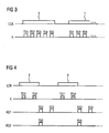
- FIG. 3 shows the associated time course of communication between the modules M, as the system master, and acting as slaves extension modules S1 to S5.
- the master M exchanges data with its slaves cyclically recurring via the communication connection K.
- a control signal LCK is provided as a clock signal, the cyclically recurring first time sections, which are referred to as telegrams T, repeated.
- telegrams T data are then sent and received by the base module M via the communication link K in data packets to the individual expansion modules S1 to S5.
- These data packets can, as in DE 102 24 311 A1 described, be constructed. That is, the modules bidirectionally exchange data in individual data packets TS1 to TS5 of typically 4 bytes.
- the first byte of a data packet TS1 to TS5 is a so-called module recognition byte
- the second and third bytes contain the data to be communicated for the addressed module
- the last byte contains a kind of checksum of the previous three bytes.
- the master M bidirectionally with each of its assigned slaves via the serial communication link K within a telegram T exchange data in individual data packets TS1 to TS5.
- this communication method has the disadvantage that it is relatively time-consuming, since within a telegram each of the slaves, here S1 to S5, must be addressed by the master M.
- the series of expansion modules is divided into at least two groups G1 and G2.
- the first expansion module is assigned a status as group master S1 'for the two subsequent modules S2 and S3, and thus the first group G1 is formed.
- the second group G2 is formed by also assigning the status as group master for S5 to the fourth expansion module S4 '.
- This assignment of individual expansion modules to the groups and the number of expansion modules per group will essentially depend on how the functions of the individual expansion modules must interact during operation of the motor feeder.
- FIG. 4 shows the necessary chronological course of the communication.
- a control signal LCK is provided.
- a control signal LCK is provided.
- a global data exchange (TS1 ', TS4') via the communication link K.
- the other expansion modules S2, S3, S5, etc. pass through the data transmitted here almost only as a shift register.
- slaves S1 'and S4' become group masters, which ignore their inputs, so that in the time intervals between the telegrams T, only communication within the groups G1 and G2 can then occur.
- the expansion modules S2, S3 and S5 switch over from the mere pushing through of the data so that they now communicate with the expansion modules S1 'and S4'.
- a local communication can be established without influencing the actual global communication.
Description
- Die Erfindung betrifft ein Kommunikationsverfahren zur seriellen Datenübertragung in der Automatisierungstechnik gemäß Anspruch 1 sowie einen entsprechenden Motorabzweig gemäß Ansprüch 4.
- Ziel der Automatisierungstechnik ist es, dass Maschinen oder Anlagen völlig selbstständig und unabhängig vom Menschen arbeiten. Je besser dieses Ziel erreicht wird, umso höher ist der Automatisierungsgrad. Dazu müssen allen Ebenen, angefangen von einer zentralen Steuerung, der so genannten SPS, bis hin zu den Motorabzweigen, bzw. Motorsteuerungen in der Feldebene miteinander kommunizieren.
- Motorabzweige schützen und steuern den Motor dabei unabhängig von der übergeordneten zentralen Steuerung. Auch bei Ausfall der SPS, oder bei einer Störung der Kommunikation mit dieser SPS, bleibt der Motor vollständig geschützt und steuerbar.
- Heute bekannte Motorabzweige sind bereits modular und damit als flexible Systeme aufgebaut. Ein Grundgerät als Basismodul realisiert dazu bereits alle für den Betrieb des Motorabzweigs notwendigen Schutz- und Steuerungsfunktionen. Bei Bedarf lässt sich dieses Basismodul über seine Systemschnittstellen mit Erweiterungsmodulen mit zusätzlichen Funktionen ergänzen. So kann beispielsweise die Art und Anzahl der binären oder analogen Ein- und Ausgänge schrittweise erhöht werden. Oder es kann ein zusätzliches Strom- bzw. Spannungserfassungsmodul zur Überwachung leistungsbezogener Messgrößen (z.B. für ein Energiemanagement)verwendet werden, usw. Damit diese Funktionen aber auch genutzt werden können, müssen die Erweiterungsmodule mit dem Basismodul kommunizieren und kontinuierlich Daten austauschen.
- Die
WO 91/14324 A - In der
DE 102 24 311 A1 ist bereits ein Verfahren zur seriellen Kommunikation zwischen einem Basismodul und einer Reihe von Erweiterungsmodulen beschrieben, welches so bei einem Motorabzweig zum Einsatz kommen könnte. Bei dem hier beschriebenen bidirektionalen Kommunikationsverfahren werden im Sinne eines seriellen Schieberegisters Daten zwischen dem Basismodul und den nachfolgenden Erweiterungsmodulen so verschoben und ausgetauscht, dass neben der einfachen Erkennung der Erweiterungsmodule auch die Datenübertragung mit geringem technischen Aufwand realisiert werden kann. - Dieses Verfahren hat aber den Nachteil, dass durch die serielle Kommunikation durch alle Module hindurch, die Kommunikation zwischen Basismodul und den Erweiterungsmodulen relativ langsam verläuft, da alle Erweiterungsmodule die vom Basismodul gesendeten Daten beachten müssen.
- Aufgabe der Erfindung ist es deshalb, ein Kommunikationsverfahren für eine schnellere Kommunikation zwischen einer seriellen Anordnung von Basis- und Erweiterungsmodulen, insbesondere von Modulen für Motorabzweige, bereitzustellen.
- Diese Aufgabe wird gelöst durch das Kommunikationsverfahren nach Anspruch 1.
- Erfindungsgemäß werden dadurch, dass einzelnen Erweiterungsmodulen ein Status als Gruppenmaster für die, ihnen jeweils seriell nachfolgenden Erweiterungsmodule zugewiesen wird, und dass das Basismodul in Abhängigkeit von dieser Zuordnung mit den einzelnen Erweiterungsmodulen kommuniziert, die Anzahl der Erweiterungsmodule in zumindest zwei Gruppen untergliedert, die auf unterschiedliche Weise angesprochen werden können.
- Dabei wird das Basismodul zyklisch in, als Telegramme bezeichneten, ersten Zeitabschnitten über die Kommunikationsverbindung nur mit denjenigen Erweiterungsmodulen Daten austauschen, denen der Status als Gruppenmaster zugeordnet ist, und die Erweiterungsmodule, denen nicht der Status als Gruppenmaster zugeordnet ist, werden die kommunizierten Daten durchreichen. Durch eine solche, auf wenige Erweiterungsmodule eingeschränkte, "globale" Kommunikation reduziert sich für das Basismodul der für die eigentlichen Telgrammphase benötigte Zeitaufwand.
- In zweiten Zeitabschnitten zwischen den Telegrammen können die Gruppenmaster dann Daten mit den jeweils ihnen zugeordneten Erweiterungsmodulen austauschen. Vorteilhafterweise werden die Gruppenmaster dazu in diesen Zeitabschnitten zwischen den Telegrammen die vom seriell vorhergehenden Erweiterungsmodul oder Basismodul übertragenen Daten ignorieren. Somit kommt es in den Pausenzeiten nur zu einer "lokalen" Kommunikation und damit zu einem lokalen Datenaustausch zwischen einigen wenigen Erweiterungsmodulen, nämlich denen, die der jeweiligen lokalen Gruppe angehören, und deren Gruppenmaster.
- Durch die erfindungsgemäße Differenzierung zwischen globalem und lokalem Datenaustausch lässt sich somit insgesamt eine schnellere und effizientere Kommunikation zwischen den Modulen des Motorabzweigs erreichen. Kommunizierte Daten werden jetzt in Abhängigkeit vom Status eines Erweiterungsmoduls unterschiedlich behandelt und müssen nicht mehr von allen Modulen beachtet werden. Somit lassen sich die Übertragungswege und damit die Laufzeiten für den Datenaustausch erheblich verkürzen.
- In einer weiteren vorteilhaften Ausführungsform wird das Basismodul über die Kommunikationsverbindung zusätzlich ein Steuersignal senden, das die Erweiterungsmodule darüber informiert, ob erste Zeitabschnitte als Telegramme oder zweite Zeitabschnitte zwischen den Telegrammen vorliegen. Dieses Steuersignal kann ein vorgegebenes zyklisch wiederkehrendes Binärsignal sein, das in der Kommunikationsverbindung entweder über die gleiche Leitung wie die Daten, oder über eine zusätzliche Leitung gesendet wird. Zudem könnte das Steuersignal vom Basismodul zeitlich angepasst werden, um so während des Betriebs des Motorabzweigs den Datenaustausch auf der globalen und lokalen Ebene dynamisch zu steuern. Durch diese dynamische Zuweisung ist eine zeitlich variierende Gruppenbildung innerhalb des Gesamtsystems möglich, so dass die Daten angepasst an die aktuelle Situation, global noch schneller an die richtigen Stellen transportiert und dort lokal in den einzelnen Untergruppen verarbeitet werden.
- Anhand der nachfolgenden Figuren soll nun exemplarisch die Erfindung beschrieben werden. Dabei zeigen:
- FIG 1
- einen bekannten seriellen Systemaufbau,
- FIG 2
- schematisch das erfindungsgemäße Prinzip,
- FIG 3
- eine zyklische Kommunikation bei einem bekannten seriellen Datenaustausch und
- FIG 4
- die erfindungsgemäße zyklische Kommunikation.
- In
FIG 1 ist schematisch ein heute üblicher Systemaufbau eines Motorabzweigs, bestehend aus einem Basismodul M und fünf Erweiterungsmodulen S1 bis S5, dargestellt. Das Basismodul M ist hier der Systemmaster, der mit den in Reihe geschalteten Erweiterungsmodulen kommuniziert. Das Basismodul M stellt dabei das Grundgerät eines Motorabzweigs dar, das alle notwendigen Grundfunktionen enthält, die den damit gesteuerten Motor vor Überlast, Erdschluss und zu hoher Erwärmung schützt. Die Erweiterungsmodule S1 bis S5 sind über eine nicht näher dargestellte Systemschnittstelle des Grundgerätes M mit diesem über die serielle Kommunikationsverbindung K verbunden. Die hier schematisch dargestellten Erweiterungsmodule S1 bis S5 können Zusatzgeräte, wie beispielsweise zusätzliche Ein/Ausgabebausteine, Strom- bzw. Spannungsüberwachungsbausteine oder Bedien- bzw. Anzeigebausteine, sein. Je nach Anzahl der gewünschten Erweiterungsfunktionen wird so mittels der Kommunikationsverbindung K die Systemschnittstelle des Basismoduls mit einem Eingang des ersten Erweiterungsmoduls S1, dessen Ausgang dann mit dem Eingang des nächsten Erweiterungsmoduls S2, usw. verbunden. -
FIG 3 zeigt den dazugehörigen zeitlichen Verlauf der Kommunikation zwischen den Modulen M, als Systemmaster, und den als Slaves fungierenden Erweiterungsmodulen S1 bis S5. über die Kommunikationsverbindung K tauscht der Master M, zyklisch wiederkehrend Daten mit seinen Slaves aus. Dazu ist ein Steuersignal LCK als Taktsignal vorgesehen, das zyklisch wiederkehrend erste Zeitabschnitte, die als Telegramme T bezeichnet sind, wiederholt. Während dieser Telegramme T werden dann vom Basismodul M über die Kommunikationsverbindung K Daten in Datenpaketen an die einzelnen Erweiterungsmodule S1 bis S5 gesendet und empfangen. Diese Datenpakete können dabei, so wie inDE 102 24 311 A1 beschrieben, aufgebaut sein. Das heißt, die Module tauschen bidirektional Daten in einzelnen Datenpaketen TS1 bis TS5 von typischerweise 4 Byte aus. Das erste Byte eines Datenpaktes TS1 bis TS5 ist dabei ein so genanntes Modulerkennungsbyte, das zweite und das dritte Byte enthalten die zu kommunizierenden Daten für das angesprochene Modul und das letzte Byte enthält eine Art Prüfsumme der vorherigen drei Bytes. So kann der Master M mit jedem der ihm zugeordneten Slaves über die serielle Kommunikationsverbindung K bidirektional innerhalb eines Telegramms T Daten in einzelnen Datenpaketen TS1 bis TS5 austauschen. Dieses Kommunikationsverfahren hat aber den Nachteil, dass es relativ zeitaufwändig ist, da innerhalb eines Telegramms jeder der Slaves, hier S1 bis S5, vom Master M angesprochen werden muss. - In
FIG 2 ist nun schematisch die erfindungsgemäße Struktur der Module dargestellt. Die Serie von Erweiterungsmodulen wird dazu in mindestens zwei Gruppen G1 und G2 unterteilt. Dazu wird beispielsweise dem ersten Erweiterungsmodul ein Status als Gruppenmaster S1' für die beiden nachfolgenden Module S2 und S3 zugeordnet und damit die erste Gruppe G1 gebildet. Die zweite Gruppe G2 wird dadurch gebildet, dass auch dem vierten Erweiterungsmodul S4' der Status als Gruppenmaster für S5 zugeordnet wird. Diese Zuordnung einzelner Erweiterungsmodule zu den Gruppen und die Anzahl der Erweiterungsmodule pro Gruppe wird dabei im Wesentlichen davon abhängen, wie die Funktionen der einzelnen Erweiterungsmodule während des Betriebs des Motorabzweigs zusammenspielen müssen. -
FIG 4 zeigt den dazu notwendigen zeitlichen Verlauf der Kommunikation. Dazu ist wiederum ein Steuersignal LCK vorgesehen. Im Gegensatz zu der aus derDE 102 24 311 A1 bekannten Datenübertragung kommt es hier, während der Telegramme T aber nur zwischen dem Master M und den Erweiterungsmodulen S1' und S4', denen der Status Gruppenmaster zugewiesen wurde, zu einem globalen Datenaustausch (TS1', TS4') über die Kommunikationsverbindung K. Während dieser Telegrammphase werden die übrigen Erweiterungsmodule S2, S3, S5, usw. die hier übertragenen Daten quasi nur als Schieberegister durchreichen. - Am Ende des zyklischen Telegramms T werden aus den Slaves S1' und S4' Gruppenmaster, welche ihre Eingänge ignorieren, so dass es dann in den Zeitabschnitten zwischen den Telegrammen T ausschließlich zu einer Kommunikation innerhalb der Gruppen G1 und G2 kommen kann. Zeitgleich schalten die Erweiterungsmodule S2,S3 und S5 vom reinen Durchschieben der Daten so um, dass sie nunmehr mit den Erweiterungsmodulen S1' und S4' kommunizieren. Somit kann eine lokale Kommunikation ohne Beeinflussung der eigentlichen globalen Kommunikation aufgebaut werden.
- Da Daten somit nur noch global (K) und lokal (KG1, KG2) zwischen den jeweils entsprechend zugeordneten Modulen ausgetauscht werden, kann insgesamt die Kommunikationszeit innerhalb eines erfindungsgemäß ausgebildeten Motorabzweigs verringert werden. Erfolgt diese Zuweisung dynamisch durch ein entsprechend angepasstes Steuersignal, kann die Kommunikationszeit noch weiter optimiert werden.
Claims (4)
- Kommunikationsverfahren zur seriellen Datenübertragung in der Automatisierungstechnik, mit einem Basismodul (M) als Systemmaster, einer Anzahl von Erweiterungsmodulen (S1,S2,S3, S4,S5,...) als Slaves, und einer bidirektionalen Kommunikationsverbindung (K), über die das Basismodul seriell mit den Erweiterungsmodulen kommuniziert, wobei die Anzahl der Erweiterungsmodule in zumindest zwei Gruppen (G1,G2) untergliedert wird indem zumindest zwei der Erweiterungsmodule (S1',S4') ein Status als Gruppenmaster für die, ihnen in der jeweiligen Gruppe seriell nachfolgenden Erweiterungsmodule (S2,S3,S5,...) zugewiesen wird,
dadurch gekennzeichnet, dass- zwischen Basismodul (M) und den Erweiterungsmodulen zyklisch in, als Telegramme (T1,T2,...) bezeichneten, ersten Zeitabschnitten nur mit denjenigen Erweiterungsmodulen (S1',S4') Daten ausgetauscht werden, denen der Status als Gruppenmaster zugeordnet ist, und von den Erweiterungsmodulen (S2,S3,S5,...), denen nicht der Status als Gruppenmaster zugeordnet ist, die kommunizierten Daten durchgereicht werden, und- in zweiten Zeitabschnitten, zwischen den Telegrammen (T1, T2,...), Daten zwischen den Gruppenmastern (S1',S4,') und den jeweils ihnen zugeordneten Erweiterungsmodulen (S2, S3,S5,...) der jeweiligen Gruppe (G1,G2) ausgetauscht werden. - Kommunikationsverfahren nach Anspruch 1,
dadurch gekennzeichnet, dass in den Zeitabschnitten zwischen den Telegrammen (T1,T2,..) von den Gruppenmastern (S1',S4') die vom seriell vorhergehenden Erweiterungsmodul (S3) oder Basismodul (M) übertragenen Daten ignoriert werden. - Kommunikationssystem nach einem der Ansprüche 1 oder 2,
dadurch gekennzeichnet, dass vom Basismodul (M) über die Kommunikationsverbindung (K) zusätzlich ein Steuersignal (S) gesendet wird, das die Erweiterungsmodule (S1',S2,S3,S4',S5,...) darüber informiert, ob erste Zeitabschnitte als Telegramme (T1,T2) oder zweite Zeitabschnitte zwischen den Telegrammen vorliegen. - Motorabzweig für ein Motormanagementsystem in der Automatisierungstechnik, mit einem Basismodul (M) mit Grundfunktionen für den Motorabzweig, und einer Anzahl von Erweiterungsmodulen (S1',S2,S3,S4',S5,...), die mittels eines Kommunikationsverfahren nach einem der Ansprüche 1 bis 3 miteinander kommunizieren.
Applications Claiming Priority (1)
| Application Number | Priority Date | Filing Date | Title |
|---|---|---|---|
| PCT/EP2008/000917 WO2009097871A1 (de) | 2008-02-06 | 2008-02-06 | Kommunikationssystem und -verfahren mit gruppenmastern zur seriellen datenübertragung in der automatisierungstechnik |
Publications (2)
| Publication Number | Publication Date |
|---|---|
| EP2241062A1 EP2241062A1 (de) | 2010-10-20 |
| EP2241062B1 true EP2241062B1 (de) | 2014-12-17 |
Family
ID=39942887
Family Applications (1)
| Application Number | Title | Priority Date | Filing Date |
|---|---|---|---|
| EP08707581.8A Active EP2241062B1 (de) | 2008-02-06 | 2008-02-06 | Kommunikationssystem und -verfahren mit gruppenmastern zur seriellen datenübertragung in der automatisierungstechnik |
Country Status (6)
| Country | Link |
|---|---|
| US (1) | US8578077B2 (de) |
| EP (1) | EP2241062B1 (de) |
| KR (1) | KR101257153B1 (de) |
| CN (1) | CN101919210B (de) |
| BR (1) | BRPI0822259A2 (de) |
| WO (1) | WO2009097871A1 (de) |
Families Citing this family (4)
| Publication number | Priority date | Publication date | Assignee | Title |
|---|---|---|---|---|
| KR102023534B1 (ko) | 2015-04-17 | 2019-09-23 | 엘에스산전 주식회사 | 슬레이브 디바이스 및 이의 제어 방법 |
| EP3185485B1 (de) * | 2015-12-21 | 2018-10-10 | ViewMove Technologies Inc. | Kommunikationssystem mit zugbusarchitektur |
| TWI612788B (zh) * | 2015-12-21 | 2018-01-21 | 視動自動化科技股份有限公司 | 具有鏈結匯流排的通訊系統 |
| JP6939665B2 (ja) * | 2018-03-15 | 2021-09-22 | オムロン株式会社 | ネットワークシステム |
Family Cites Families (10)
| Publication number | Priority date | Publication date | Assignee | Title |
|---|---|---|---|---|
| NL9000608A (nl) | 1990-03-16 | 1991-10-16 | Locamation Beheer B V | Communicatiestelsel. |
| SE501984C2 (sv) * | 1994-04-18 | 1995-07-03 | Kvaser Consultant Ab | Anordning för att eliminera funktionsstörningar och/eller möjliggöra höghastighetsöverföring i seriell bus-förbindelse och till denna anslutna sändar- och mottagarenheter |
| DE19514696B4 (de) * | 1994-04-18 | 2006-03-09 | Kvaser Consultant Ab | System zur Beseitigung von Störungen bzw. zur Ermöglichung einer Hochgeschwindigkeitsübertragung in einer seriellen Bus-Schaltung sowie mit letzterer verbundene Sende- und Empfangsgeräte |
| SE0001491D0 (sv) * | 2000-04-25 | 2000-04-25 | Scania Cv Ab | Funktionsuppdelad deplexkommunikationsbuss |
| DE10047923C2 (de) * | 2000-09-27 | 2003-04-10 | Siemens Ag | Verfahren zur Erzeugung einer Verbindungs-Redundanz für ein serielles Kommunikationssystem mit einer Mastereinheit und einer Mehrzahl von Slaveeinheiten, die untereinander als Aneinanderreihung von Punkt-zu-Punkt-Verbindungen in Linientopologie verbunden sind, sowie korrespondierendes serielles Kommunikationssystem |
| JP3584873B2 (ja) * | 2000-10-31 | 2004-11-04 | ヤマハ株式会社 | 通信制御装置及び通信システム |
| KR100423998B1 (ko) * | 2001-07-05 | 2004-03-22 | 주식회사 휴로펙 | 필드 버스 통신 시스템 |
| JP3916953B2 (ja) * | 2001-12-28 | 2007-05-23 | 日本テキサス・インスツルメンツ株式会社 | 可変時分割多重伝送システム |
| JP4204226B2 (ja) | 2001-12-28 | 2009-01-07 | 日本テキサス・インスツルメンツ株式会社 | デバイス識別方法、データ伝送方法、デバイス識別子付与装置、並びにデバイス |
| DE10224311B4 (de) | 2002-05-31 | 2004-07-08 | Siemens Ag | Verfahren und Vorrichtung zur seriellen Datenübertragung |
-
2008
- 2008-02-06 CN CN200880125194.0A patent/CN101919210B/zh active Active
- 2008-02-06 BR BRPI0822259A patent/BRPI0822259A2/pt not_active IP Right Cessation
- 2008-02-06 EP EP08707581.8A patent/EP2241062B1/de active Active
- 2008-02-06 WO PCT/EP2008/000917 patent/WO2009097871A1/de active Application Filing
- 2008-02-06 KR KR1020107017480A patent/KR101257153B1/ko active IP Right Grant
- 2008-02-06 US US12/866,050 patent/US8578077B2/en active Active
Also Published As
| Publication number | Publication date |
|---|---|
| CN101919210B (zh) | 2013-05-29 |
| US8578077B2 (en) | 2013-11-05 |
| BRPI0822259A2 (pt) | 2023-04-18 |
| WO2009097871A1 (de) | 2009-08-13 |
| US20100332705A1 (en) | 2010-12-30 |
| CN101919210A (zh) | 2010-12-15 |
| KR20100117598A (ko) | 2010-11-03 |
| KR101257153B1 (ko) | 2013-04-22 |
| EP2241062A1 (de) | 2010-10-20 |
Similar Documents
| Publication | Publication Date | Title |
|---|---|---|
| EP2067081B1 (de) | Verfahren zum synchronisieren zweier steuereinrichtungen und redundant aufgebaute automatisierungsvorrichtung | |
| EP1622039B1 (de) | Verfahren und Vorrichtung zur Adressvergabe an Teilnehmer eines Bussystems | |
| DE102009042354A1 (de) | Verfahren und Vorrichtung zur sicherheitsgerichteten Kommunikation im Kommunikations-Netzwerk einer Automatisierungs-Anlage | |
| EP0597561B1 (de) | Übertragungssystem zum Datenaustausch | |
| DE102006055887A1 (de) | Kommunikationssystem mit einer Master-Slave-Struktur | |
| DE102016000126A1 (de) | Serielles Bussystem mit Koppelmodulen | |
| DE102011087152B4 (de) | Testsystem und Testverfahren für Kabelbäume | |
| DE102006004339A1 (de) | Redundantes Kommunikationsnetzwerk | |
| EP3632040A1 (de) | Verarbeitung von prozessdaten | |
| EP2241062B1 (de) | Kommunikationssystem und -verfahren mit gruppenmastern zur seriellen datenübertragung in der automatisierungstechnik | |
| EP2214068A1 (de) | Automatisierungssystem mit einem programmierbaren Matrixmodul | |
| EP3039494B1 (de) | Automatisierungssystem | |
| DE102008004798B4 (de) | Konfigurations- und Anzeigemodul für busvernetzte Teilnehmer | |
| EP2418580B1 (de) | Verfahren zum Betreiben eines Netzwerkes und Netzwerk | |
| EP1695158B1 (de) | Eigensichere datenübertragungseinrichtung | |
| EP3267271B1 (de) | Automatisierungssystem und verfahren zum betrieb | |
| EP2566110B1 (de) | Verfahren zum Übertragen von Telegrammen in einem Automatisierungssystem | |
| EP2217977B1 (de) | Automatisierungssystem und steuerungsvorrichtung zum identifizieren eines anschlusselementes | |
| DE102006049636B4 (de) | Buskoppler sowie Kommunikationssystem mit Buskoppler | |
| EP3632054B1 (de) | Bestimmung von datenbusteilnehmern eines lokalbusses | |
| WO2016079091A1 (de) | Verfahren zum betreiben eines ersten und zumindest eines zweiten feldgerätes | |
| DE19952883A1 (de) | Bussystem für eine Mehrzahl von Teilnehmern | |
| DE102011004363B4 (de) | Steuervorrichtung zum Steuern von Netzwerkteilnehmern, Verfahren zum Betreiben eines Computernetzwerks und Computernetzwerk | |
| EP3631630B1 (de) | Verteilte verarbeitung von prozessdaten | |
| EP2817923B1 (de) | Rechnernetzwerk mit einer ringförmigen busverbindung |
Legal Events
| Date | Code | Title | Description |
|---|---|---|---|
| PUAI | Public reference made under article 153(3) epc to a published international application that has entered the european phase |
Free format text: ORIGINAL CODE: 0009012 |
|
| 17P | Request for examination filed |
Effective date: 20100713 |
|
| AK | Designated contracting states |
Kind code of ref document: A1 Designated state(s): AT BE BG CH CY CZ DE DK EE ES FI FR GB GR HR HU IE IS IT LI LT LU LV MC MT NL NO PL PT RO SE SI SK TR |
|
| AX | Request for extension of the european patent |
Extension state: AL BA MK RS |
|
| DAX | Request for extension of the european patent (deleted) | ||
| RAP1 | Party data changed (applicant data changed or rights of an application transferred) |
Owner name: SIEMENS AKTIENGESELLSCHAFT |
|
| REG | Reference to a national code |
Ref country code: DE Ref legal event code: R079 Ref document number: 502008012504 Country of ref document: DE Free format text: PREVIOUS MAIN CLASS: H04L0012403000 Ipc: H04L0012400000 |
|
| GRAP | Despatch of communication of intention to grant a patent |
Free format text: ORIGINAL CODE: EPIDOSNIGR1 |
|
| RIC1 | Information provided on ipc code assigned before grant |
Ipc: G05B 19/04 20060101ALI20140618BHEP Ipc: H04L 12/403 20060101ALI20140618BHEP Ipc: H04L 12/40 20060101AFI20140618BHEP Ipc: G06F 13/42 20060101ALI20140618BHEP |
|
| INTG | Intention to grant announced |
Effective date: 20140718 |
|
| GRAS | Grant fee paid |
Free format text: ORIGINAL CODE: EPIDOSNIGR3 |
|
| GRAA | (expected) grant |
Free format text: ORIGINAL CODE: 0009210 |
|
| AK | Designated contracting states |
Kind code of ref document: B1 Designated state(s): AT BE BG CH CY CZ DE DK EE ES FI FR GB GR HR HU IE IS IT LI LT LU LV MC MT NL NO PL PT RO SE SI SK TR |
|
| REG | Reference to a national code |
Ref country code: GB Ref legal event code: FG4D Free format text: NOT ENGLISH |
|
| REG | Reference to a national code |
Ref country code: CH Ref legal event code: EP |
|
| REG | Reference to a national code |
Ref country code: IE Ref legal event code: FG4D Free format text: LANGUAGE OF EP DOCUMENT: GERMAN |
|
| REG | Reference to a national code |
Ref country code: AT Ref legal event code: REF Ref document number: 702535 Country of ref document: AT Kind code of ref document: T Effective date: 20150115 |
|
| REG | Reference to a national code |
Ref country code: DE Ref legal event code: R096 Ref document number: 502008012504 Country of ref document: DE Effective date: 20150129 |
|
| REG | Reference to a national code |
Ref country code: SE Ref legal event code: TRGR |
|
| PG25 | Lapsed in a contracting state [announced via postgrant information from national office to epo] |
Ref country code: FI Free format text: LAPSE BECAUSE OF FAILURE TO SUBMIT A TRANSLATION OF THE DESCRIPTION OR TO PAY THE FEE WITHIN THE PRESCRIBED TIME-LIMIT Effective date: 20141217 Ref country code: LT Free format text: LAPSE BECAUSE OF FAILURE TO SUBMIT A TRANSLATION OF THE DESCRIPTION OR TO PAY THE FEE WITHIN THE PRESCRIBED TIME-LIMIT Effective date: 20141217 Ref country code: NO Free format text: LAPSE BECAUSE OF FAILURE TO SUBMIT A TRANSLATION OF THE DESCRIPTION OR TO PAY THE FEE WITHIN THE PRESCRIBED TIME-LIMIT Effective date: 20150317 |
|
| REG | Reference to a national code |
Ref country code: LT Ref legal event code: MG4D |
|
| PG25 | Lapsed in a contracting state [announced via postgrant information from national office to epo] |
Ref country code: LV Free format text: LAPSE BECAUSE OF FAILURE TO SUBMIT A TRANSLATION OF THE DESCRIPTION OR TO PAY THE FEE WITHIN THE PRESCRIBED TIME-LIMIT Effective date: 20141217 Ref country code: GR Free format text: LAPSE BECAUSE OF FAILURE TO SUBMIT A TRANSLATION OF THE DESCRIPTION OR TO PAY THE FEE WITHIN THE PRESCRIBED TIME-LIMIT Effective date: 20150318 Ref country code: HR Free format text: LAPSE BECAUSE OF FAILURE TO SUBMIT A TRANSLATION OF THE DESCRIPTION OR TO PAY THE FEE WITHIN THE PRESCRIBED TIME-LIMIT Effective date: 20141217 |
|
| PG25 | Lapsed in a contracting state [announced via postgrant information from national office to epo] |
Ref country code: NL Free format text: LAPSE BECAUSE OF FAILURE TO SUBMIT A TRANSLATION OF THE DESCRIPTION OR TO PAY THE FEE WITHIN THE PRESCRIBED TIME-LIMIT Effective date: 20141217 |
|
| PG25 | Lapsed in a contracting state [announced via postgrant information from national office to epo] |
Ref country code: ES Free format text: LAPSE BECAUSE OF FAILURE TO SUBMIT A TRANSLATION OF THE DESCRIPTION OR TO PAY THE FEE WITHIN THE PRESCRIBED TIME-LIMIT Effective date: 20141217 Ref country code: EE Free format text: LAPSE BECAUSE OF FAILURE TO SUBMIT A TRANSLATION OF THE DESCRIPTION OR TO PAY THE FEE WITHIN THE PRESCRIBED TIME-LIMIT Effective date: 20141217 Ref country code: CZ Free format text: LAPSE BECAUSE OF FAILURE TO SUBMIT A TRANSLATION OF THE DESCRIPTION OR TO PAY THE FEE WITHIN THE PRESCRIBED TIME-LIMIT Effective date: 20141217 Ref country code: SK Free format text: LAPSE BECAUSE OF FAILURE TO SUBMIT A TRANSLATION OF THE DESCRIPTION OR TO PAY THE FEE WITHIN THE PRESCRIBED TIME-LIMIT Effective date: 20141217 Ref country code: RO Free format text: LAPSE BECAUSE OF FAILURE TO SUBMIT A TRANSLATION OF THE DESCRIPTION OR TO PAY THE FEE WITHIN THE PRESCRIBED TIME-LIMIT Effective date: 20141217 |
|
| PG25 | Lapsed in a contracting state [announced via postgrant information from national office to epo] |
Ref country code: IS Free format text: LAPSE BECAUSE OF FAILURE TO SUBMIT A TRANSLATION OF THE DESCRIPTION OR TO PAY THE FEE WITHIN THE PRESCRIBED TIME-LIMIT Effective date: 20150417 Ref country code: PL Free format text: LAPSE BECAUSE OF FAILURE TO SUBMIT A TRANSLATION OF THE DESCRIPTION OR TO PAY THE FEE WITHIN THE PRESCRIBED TIME-LIMIT Effective date: 20141217 |
|
| REG | Reference to a national code |
Ref country code: DE Ref legal event code: R097 Ref document number: 502008012504 Country of ref document: DE |
|
| PG25 | Lapsed in a contracting state [announced via postgrant information from national office to epo] |
Ref country code: LU Free format text: LAPSE BECAUSE OF FAILURE TO SUBMIT A TRANSLATION OF THE DESCRIPTION OR TO PAY THE FEE WITHIN THE PRESCRIBED TIME-LIMIT Effective date: 20150206 |
|
| REG | Reference to a national code |
Ref country code: CH Ref legal event code: PL |
|
| PLBE | No opposition filed within time limit |
Free format text: ORIGINAL CODE: 0009261 |
|
| STAA | Information on the status of an ep patent application or granted ep patent |
Free format text: STATUS: NO OPPOSITION FILED WITHIN TIME LIMIT |
|
| PG25 | Lapsed in a contracting state [announced via postgrant information from national office to epo] |
Ref country code: LI Free format text: LAPSE BECAUSE OF NON-PAYMENT OF DUE FEES Effective date: 20150228 Ref country code: CH Free format text: LAPSE BECAUSE OF NON-PAYMENT OF DUE FEES Effective date: 20150228 Ref country code: MC Free format text: LAPSE BECAUSE OF FAILURE TO SUBMIT A TRANSLATION OF THE DESCRIPTION OR TO PAY THE FEE WITHIN THE PRESCRIBED TIME-LIMIT Effective date: 20141217 Ref country code: DK Free format text: LAPSE BECAUSE OF FAILURE TO SUBMIT A TRANSLATION OF THE DESCRIPTION OR TO PAY THE FEE WITHIN THE PRESCRIBED TIME-LIMIT Effective date: 20141217 |
|
| REG | Reference to a national code |
Ref country code: IE Ref legal event code: MM4A |
|
| 26N | No opposition filed |
Effective date: 20150918 |
|
| GBPC | Gb: european patent ceased through non-payment of renewal fee |
Effective date: 20150317 |
|
| PG25 | Lapsed in a contracting state [announced via postgrant information from national office to epo] |
Ref country code: GB Free format text: LAPSE BECAUSE OF NON-PAYMENT OF DUE FEES Effective date: 20150317 Ref country code: IE Free format text: LAPSE BECAUSE OF NON-PAYMENT OF DUE FEES Effective date: 20150206 |
|
| REG | Reference to a national code |
Ref country code: FR Ref legal event code: PLFP Year of fee payment: 9 |
|
| PG25 | Lapsed in a contracting state [announced via postgrant information from national office to epo] |
Ref country code: SI Free format text: LAPSE BECAUSE OF FAILURE TO SUBMIT A TRANSLATION OF THE DESCRIPTION OR TO PAY THE FEE WITHIN THE PRESCRIBED TIME-LIMIT Effective date: 20141217 |
|
| REG | Reference to a national code |
Ref country code: AT Ref legal event code: MM01 Ref document number: 702535 Country of ref document: AT Kind code of ref document: T Effective date: 20150206 |
|
| PG25 | Lapsed in a contracting state [announced via postgrant information from national office to epo] |
Ref country code: AT Free format text: LAPSE BECAUSE OF NON-PAYMENT OF DUE FEES Effective date: 20150206 |
|
| PG25 | Lapsed in a contracting state [announced via postgrant information from national office to epo] |
Ref country code: MT Free format text: LAPSE BECAUSE OF FAILURE TO SUBMIT A TRANSLATION OF THE DESCRIPTION OR TO PAY THE FEE WITHIN THE PRESCRIBED TIME-LIMIT Effective date: 20141217 |
|
| REG | Reference to a national code |
Ref country code: FR Ref legal event code: PLFP Year of fee payment: 10 |
|
| PG25 | Lapsed in a contracting state [announced via postgrant information from national office to epo] |
Ref country code: BG Free format text: LAPSE BECAUSE OF FAILURE TO SUBMIT A TRANSLATION OF THE DESCRIPTION OR TO PAY THE FEE WITHIN THE PRESCRIBED TIME-LIMIT Effective date: 20141217 Ref country code: HU Free format text: LAPSE BECAUSE OF FAILURE TO SUBMIT A TRANSLATION OF THE DESCRIPTION OR TO PAY THE FEE WITHIN THE PRESCRIBED TIME-LIMIT; INVALID AB INITIO Effective date: 20080206 |
|
| PG25 | Lapsed in a contracting state [announced via postgrant information from national office to epo] |
Ref country code: CY Free format text: LAPSE BECAUSE OF FAILURE TO SUBMIT A TRANSLATION OF THE DESCRIPTION OR TO PAY THE FEE WITHIN THE PRESCRIBED TIME-LIMIT Effective date: 20141217 |
|
| PG25 | Lapsed in a contracting state [announced via postgrant information from national office to epo] |
Ref country code: PT Free format text: LAPSE BECAUSE OF FAILURE TO SUBMIT A TRANSLATION OF THE DESCRIPTION OR TO PAY THE FEE WITHIN THE PRESCRIBED TIME-LIMIT Effective date: 20150417 Ref country code: BE Free format text: LAPSE BECAUSE OF NON-PAYMENT OF DUE FEES Effective date: 20150228 |
|
| PG25 | Lapsed in a contracting state [announced via postgrant information from national office to epo] |
Ref country code: TR Free format text: LAPSE BECAUSE OF FAILURE TO SUBMIT A TRANSLATION OF THE DESCRIPTION OR TO PAY THE FEE WITHIN THE PRESCRIBED TIME-LIMIT Effective date: 20141217 |
|
| REG | Reference to a national code |
Ref country code: FR Ref legal event code: PLFP Year of fee payment: 11 |
|
| PGFP | Annual fee paid to national office [announced via postgrant information from national office to epo] |
Ref country code: SE Payment date: 20200210 Year of fee payment: 13 |
|
| REG | Reference to a national code |
Ref country code: SE Ref legal event code: EUG |
|
| PG25 | Lapsed in a contracting state [announced via postgrant information from national office to epo] |
Ref country code: SE Free format text: LAPSE BECAUSE OF NON-PAYMENT OF DUE FEES Effective date: 20210207 |
|
| PGFP | Annual fee paid to national office [announced via postgrant information from national office to epo] |
Ref country code: IT Payment date: 20220221 Year of fee payment: 15 Ref country code: FR Payment date: 20220223 Year of fee payment: 15 |
|
| PGFP | Annual fee paid to national office [announced via postgrant information from national office to epo] |
Ref country code: DE Payment date: 20230419 Year of fee payment: 16 |
|
| PG25 | Lapsed in a contracting state [announced via postgrant information from national office to epo] |
Ref country code: IT Free format text: LAPSE BECAUSE OF NON-PAYMENT OF DUE FEES Effective date: 20230206 Ref country code: FR Free format text: LAPSE BECAUSE OF NON-PAYMENT OF DUE FEES Effective date: 20230228 |