EP2240830B1 - Beleuchtungsoptik für die mikrolithografie - Google Patents
Beleuchtungsoptik für die mikrolithografie Download PDFInfo
- Publication number
- EP2240830B1 EP2240830B1 EP08859710.9A EP08859710A EP2240830B1 EP 2240830 B1 EP2240830 B1 EP 2240830B1 EP 08859710 A EP08859710 A EP 08859710A EP 2240830 B1 EP2240830 B1 EP 2240830B1
- Authority
- EP
- European Patent Office
- Prior art keywords
- field
- illumination
- plane
- bundles
- radiation
- Prior art date
- Legal status (The legal status is an assumption and is not a legal conclusion. Google has not performed a legal analysis and makes no representation as to the accuracy of the status listed.)
- Active
Links
- 238000005286 illumination Methods 0.000 title claims description 159
- 238000001393 microlithography Methods 0.000 title claims description 8
- 230000005855 radiation Effects 0.000 claims description 130
- 210000001747 pupil Anatomy 0.000 claims description 35
- 230000003287 optical effect Effects 0.000 claims description 26
- 238000009826 distribution Methods 0.000 claims description 19
- 238000006073 displacement reaction Methods 0.000 claims description 11
- 238000003384 imaging method Methods 0.000 claims description 6
- 238000000034 method Methods 0.000 claims description 6
- 239000000463 material Substances 0.000 claims description 2
- 230000000694 effects Effects 0.000 description 13
- 230000005540 biological transmission Effects 0.000 description 12
- 230000004075 alteration Effects 0.000 description 2
- 238000010586 diagram Methods 0.000 description 2
- 238000009304 pastoral farming Methods 0.000 description 2
- 230000002238 attenuated effect Effects 0.000 description 1
- 230000001419 dependent effect Effects 0.000 description 1
- 238000001514 detection method Methods 0.000 description 1
- 238000004519 manufacturing process Methods 0.000 description 1
- 238000005259 measurement Methods 0.000 description 1
- 238000012544 monitoring process Methods 0.000 description 1
- 239000002245 particle Substances 0.000 description 1
- 239000004065 semiconductor Substances 0.000 description 1
- 230000035945 sensitivity Effects 0.000 description 1
- 230000003068 static effect Effects 0.000 description 1
- 230000001360 synchronised effect Effects 0.000 description 1
- 238000011144 upstream manufacturing Methods 0.000 description 1
Images


Classifications
-
- G—PHYSICS
- G03—PHOTOGRAPHY; CINEMATOGRAPHY; ANALOGOUS TECHNIQUES USING WAVES OTHER THAN OPTICAL WAVES; ELECTROGRAPHY; HOLOGRAPHY
- G03F—PHOTOMECHANICAL PRODUCTION OF TEXTURED OR PATTERNED SURFACES, e.g. FOR PRINTING, FOR PROCESSING OF SEMICONDUCTOR DEVICES; MATERIALS THEREFOR; ORIGINALS THEREFOR; APPARATUS SPECIALLY ADAPTED THEREFOR
- G03F7/00—Photomechanical, e.g. photolithographic, production of textured or patterned surfaces, e.g. printing surfaces; Materials therefor, e.g. comprising photoresists; Apparatus specially adapted therefor
- G03F7/70—Microphotolithographic exposure; Apparatus therefor
- G03F7/70058—Mask illumination systems
- G03F7/702—Reflective illumination, i.e. reflective optical elements other than folding mirrors, e.g. extreme ultraviolet [EUV] illumination systems
-
- G—PHYSICS
- G03—PHOTOGRAPHY; CINEMATOGRAPHY; ANALOGOUS TECHNIQUES USING WAVES OTHER THAN OPTICAL WAVES; ELECTROGRAPHY; HOLOGRAPHY
- G03F—PHOTOMECHANICAL PRODUCTION OF TEXTURED OR PATTERNED SURFACES, e.g. FOR PRINTING, FOR PROCESSING OF SEMICONDUCTOR DEVICES; MATERIALS THEREFOR; ORIGINALS THEREFOR; APPARATUS SPECIALLY ADAPTED THEREFOR
- G03F7/00—Photomechanical, e.g. photolithographic, production of textured or patterned surfaces, e.g. printing surfaces; Materials therefor, e.g. comprising photoresists; Apparatus specially adapted therefor
- G03F7/70—Microphotolithographic exposure; Apparatus therefor
- G03F7/70058—Mask illumination systems
- G03F7/70075—Homogenization of illumination intensity in the mask plane by using an integrator, e.g. fly's eye lens, facet mirror or glass rod, by using a diffusing optical element or by beam deflection
-
- G—PHYSICS
- G03—PHOTOGRAPHY; CINEMATOGRAPHY; ANALOGOUS TECHNIQUES USING WAVES OTHER THAN OPTICAL WAVES; ELECTROGRAPHY; HOLOGRAPHY
- G03F—PHOTOMECHANICAL PRODUCTION OF TEXTURED OR PATTERNED SURFACES, e.g. FOR PRINTING, FOR PROCESSING OF SEMICONDUCTOR DEVICES; MATERIALS THEREFOR; ORIGINALS THEREFOR; APPARATUS SPECIALLY ADAPTED THEREFOR
- G03F7/00—Photomechanical, e.g. photolithographic, production of textured or patterned surfaces, e.g. printing surfaces; Materials therefor, e.g. comprising photoresists; Apparatus specially adapted therefor
- G03F7/70—Microphotolithographic exposure; Apparatus therefor
- G03F7/70058—Mask illumination systems
- G03F7/70083—Non-homogeneous intensity distribution in the mask plane
-
- G—PHYSICS
- G03—PHOTOGRAPHY; CINEMATOGRAPHY; ANALOGOUS TECHNIQUES USING WAVES OTHER THAN OPTICAL WAVES; ELECTROGRAPHY; HOLOGRAPHY
- G03F—PHOTOMECHANICAL PRODUCTION OF TEXTURED OR PATTERNED SURFACES, e.g. FOR PRINTING, FOR PROCESSING OF SEMICONDUCTOR DEVICES; MATERIALS THEREFOR; ORIGINALS THEREFOR; APPARATUS SPECIALLY ADAPTED THEREFOR
- G03F7/00—Photomechanical, e.g. photolithographic, production of textured or patterned surfaces, e.g. printing surfaces; Materials therefor, e.g. comprising photoresists; Apparatus specially adapted therefor
- G03F7/70—Microphotolithographic exposure; Apparatus therefor
- G03F7/70058—Mask illumination systems
- G03F7/70191—Optical correction elements, filters or phase plates for controlling intensity, wavelength, polarisation, phase or the like
Definitions
- the invention relates to an illumination optics for microlithography.
- the invention further relates to an illumination system comprising an illumination optics of this type, a projection exposure apparatus comprising an illumination system of this type and a method of producing structured components.
- MICROLITHOGRAPHY XVI Vol. 5040, 2003, pages 45-56, describes a method of illumination pupil fill measurement and analysis and its application in a projection exposure apparatus.
- WO 03/093 902 A2 and EP 1 491 959 A1 each disclose a EUV projection exposure apparatus with an illumination system.
- an illumination optics for microlithography comprising
- the object plane is spatially separated from the superposition plane of the radiation sub-bundles of the illumination light.
- the object plane and the superposition plane do not constitute planes that are imaged into one another; the object plane may therefore be arranged directly next to the superposition plane. No optical components are required between the object plane and the superposition plane for guiding the illumination light.
- a device may be arranged for setting an illumination intensity distribution across the object field or for monitoring the illumination intensity distribution across the object field by means of a sensor, for example.
- the illumination optics according to the invention can, but need not necessarily, include a facet mirror. It is conceivable as well to use a honeycomb condenser, for example, i.e. a transmissive optical element which is divided into a plurality of individual channels, and/or at least one diffractive element for dividing the illumination light radiation bundle into the radiation sub-bundles.
- a partial superposition in other words a coinciding superposition, of sub-bundle edge portions of the radiation sub-bundles is sufficient.
- the remaining sub-bundle edge portions of the superimposed radiation sub-bundles need not coincide; in these portions, aberrations are tolerable.
- a superposition at one of the four sub-bundle edges is sufficient.
- the coinciding edge portions of the superimposed radiation sub-bundles form a common sub-bundle edge portion which is usually perpendicular to an object displacement direction of an object that is displaced during the microlithographic projection process.
- a displacement of this type takes place in a projection exposure apparatus designed as a scanner.
- the radiation sub-bundles are superimposed in the superposition plane.
- the superposition of the radiation sub-bundles by means of a field intensity setting device which is arranged in the superposition plane so as to be used as an intensity setting plane and serves for the adjustment of an intensity distribution of the illumination light across the object field, wherein the edges of the superimposed radiation sub-bundles coincide at the point where they are influencable by the field intensity setting device, provides for a virtually illumination-angle-independent effect of the field intensity setting device.
- the superposition plane serves as an intensity setting plane.
- the field intensity setting device influences the superimposed radiation sub-bundles of the illumination light radiation bundle at their point of superposition.
- the field intensity setting device influences all radiation sub-bundles which are superimposed at this point in the same way; in other words, the field intensity setting device has an effect which is independent with respect to these radiation sub-bundles and therefore with respect to the illumination angles which are assigned to these radiation sub-bundles.
- the superposition of the radiation sub-bundles takes place at least at the point where the field intensity setting device influences the illumination light radiation bundle. In the case of approximately rectangular radiation sub-bundles, for example, a superposition at the edge, which is influenced by the field intensity setting device, is sufficient. Naturally, a superposition of radiation sub-bundles or sub-bundle edge portions may also take place in regions which are not influenced by the field intensity setting device.
- a superposition of the radiation sub-bundles in the superposition plane or intensity setting plane in order to reduce or virtually avoid an illumination angle impact of the field intensity setting device is, among other things, applicable in systems in which the field intensity setting device is able to influence the superimposed radiation sub-bundles from two sides. These may be illumination optics with an intermediate image or illumination optics with transmission masks.
- the field intensity setting device defines the intensity of the illumination light in the object plane.
- a superposition of the radiation sub-bundles at a point, which is in the range of impact of the field intensity setting device furthermore allows an increased stability of the object field illumination to be achieved since a displacement of a light source used to generate the illumination light will, if at all, only have a minor impact on the effect of the field intensity setting device. This is advantageous in particular when an EUV plasma source is used.
- a field intensity setting device which comprises a plurality of individual diaphragms or stops that are arranged next to one another and at least attenuate illumination light when exposed thereto and are insertable into an illumination light radiation bundle in a direction parallel to an object displacement direction provides for a sensitive adjustment of the intensity across an object field height of the object field, in other words an object field dimension perpendicular to an object displacement direction.
- An illumination optics according to claim 5 achieves an increased number of possible applications of the field intensity setting device.
- the field intensity setting device is even applicable in situations where the object field is arranged on a reflective object such as a reflective reticle.
- the field intensity setting device may then be arranged in such a way that it does not interfere with the reflected light path of the illumination light radiation bundle.
- An arrangement of the field intensity setting device in an intensity setting plane, which coincides with a field plane of the optical assembly, may again ensure an illumination-angle-independent effect of the field intensity setting device.
- the field plane of the optical assembly describes the plane where the illumination light radiation bundle is constricted due to the bundle-guiding effect of the optical assembly, and where radiation sub-bundles are superimposed if an illumination light radiation bundle is divided into several radiation sub-bundles.
- the field plane of the optical assembly is usually the plane into which the object-field-forming components of the optical assembly are imaged. In spite of this, the field plane of the optical assembly is generally position-independent of a plane which is imaged by a downstream projection optics of a microlithographic projection exposure apparatus and which is usually referred to as object plane.
- the field plane of the optical assembly coincides with the object plane. This is not the case in the inventive illumination optics.
- the field intensity setting device which is arranged in the field plane of the optical assembly and not the object, which is usually a reticle, to be imaged.
- Prior-art field intensity setting devices are usually arranged upstream of a reticle which is arranged in the field plane of the optical assembly, in other words they are not arranged in this field plane.
- the prior-art field intensity setting device has a greater impact on radiation sub-bundles of the,illumination light radiation bundle which are assigned to particular illumination angles than on radiation sub-bundles assigned to other illumination angles; the prior-art field intensity setting devices have therefore an undesired illumination-angle-dependent effect across the object field.
- This problem was recognized by the inventors and eliminated by arranging the field intensity setting device in the field plane of the optical assembly. Surprisingly, this allows the object to be moved out of the field plane of the optical assembly without any problems. This applies in particular if a projection exposure apparatus, which includes the illumination optics, is designed as a scanning apparatus. Moreover, this applies in particular if the illumination of the object field is carried out using a numerical aperture of the illumination light radiation bundle, which is smaller than or equal to 0.1.
- An arrangement in which the object plane is adjacent to the intensity setting plane in such a way that there is no pupil plane of the optical assembly between the intensity setting plane and the object plane is particularly compact.
- a distance between the intensity setting plane and the object plane is in the range of between 5 mm and 20 mm prevents spatial conflicts or dosing errors, in other words unwanted aberrations in the illumination intensity entering the object field.
- Preferred distances are in the range of between 10 mm and 20 mm, in particular in the range of 15 mm or 16 mm.
- optical assembly comprises a field facet mirror with a plurality of field facets whose images are at least partially superimposed in the object field permits easy control of an illumination angle distribution of the illumination of the object field.
- a configuration of the field facets such that the field facets have a higher x/y aspect ratio than the object field, which means that proportionally speaking, they are narrower than the object field when seen in the object displacement direction, may avoid an overexposure of the object field as a result of diverging field facet images in the object plane or in the reticle plane due to the fact that the object is not disposed in the field plane, also referred to as diaphragm plane, of the optical assembly in which the partial fields, in other words the images of object-field-forming components of the optical assembly of the illumination optics, are arranged in such a way that the feedback on the illumination angle distribution is minimized.
- An arrangement in which an edge of the illumination light radiation bundle facing the individual diaphragms is illuminated by all field facets of the field facet mirror ensures a relatively homogeneous impact of the field intensity setting device on all field facet images, thus avoiding an unwanted impact on the illumination angle distribution during the use of the field intensity setting device.
- This ensures a particularly high system stability, wherein in particular a spatial displacement of a light source of the illumination light is more or less unproblematic. This is advantageous in particular when the light source is an EUV plasma source.
- An arrangement in which an edge of the illumination light radiation bundle facing the individual diaphragms is illuminated in the field plane by a subgroup of all field facets of the field facet mirror ensures an illumination-angle-independent effect of the field intensity setting device even if a coincidence of the field facet images at the edge of the illumination light radiation bundle in the field plane facing the individual diaphragms is not achievable for all field facet images.
- An assignment of a given distribution of illumination angles to the field facets of the subgroup improves an illumination angle independence of the field intensity setting device in those cases in which a perfect superposition at the edge of the illumination light radiation bundle in the field plane facing the individual diaphragms is not achievable at all or only to a minor extent.
- the defined distribution of illumination angles may for instance be generated by means of a statistical function. This not only ensures an illumination angle independence of the intensity setting device but also guarantees a defined impact on the illumination angles.
- a pupil facet mirror with a plurality of pupil facets which are assigned to the field facets in the light path of the illumination light permits easy control of an illumination angle distribution across the object field.
- Pupil facets which are tiltable for adjusting a superposition of the illumination light in the intensity setting plane allow the individual radiation sub-bundles of the illumination light radiation bundle to be selectively displaced and oriented in the intensity setting plane in order to optimize the subposition of these radiation sub-bundles in a region that is in the range of impact of the field intensity setting device.
- Individual diaphragms which are, at least in some portions, at least partially transparent enhance the sensitivity of the intensity effect of the field intensity setting device with respect to a displacement of individual diaphragms and with respect to a change of position of the field intensity setting device relative to illumination light radiation bundle.
- a projection exposure apparatus 1 for microlithography serves to produce a microstructured or nanostructured electronic semiconductor component.
- a light source 2 emits EUV radiation in the wavelength range of between 5 nm and 30 nm, for example.
- a bundle 3 of useful radiation serves for illumination and projection. Downstream of the light source 2, the bundle 3 of useful radiation initially passes through a collector 4 which may for example be a nested collector with a prior-art multiple-shell configuration. Downstream of the collector 4, the bundle 3 of useful radiation initially passes through an intermediate focal plane 5 which may be used to separate unwanted portions of radiation or particles from the bundle 3 of useful radiation. Having passed through the intermediate focal plane 5, the bundle 3 of useful radiation initially hits a field facet mirror 6.
- the drawing includes in each case an xyz coordinate system in order to facilitate the description of positional relationships.
- the x-axis extends into said plane perpendicular thereto.
- the y-axis extends towards the left in Fig. 1 .
- the z-axis extends upwardly in Fig. 1 .
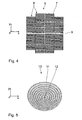
- Fig. 4 shows, by way of example, a facet arrangement of field facets 7 of the field facet mirror 6.
- the field facets 7 are rectangular and have in each case the same x/y aspect ratio.
- the field facets 7 define a reflective surface of the field facet mirror 6 and are arranged in four columns of in each case six field facet groups 8.
- the field facet groups 8 usually comprise in each case seven field facets 7.
- the two field facet groups 8 near the edge, which are included in the two central field facet columns, comprise in each case four additional field facets 7 and therefore comprise a total of eleven field facets 7.
- the facet arrangement of the field facet mirror 6 has gaps 9 in which the field facet mirror 6 is shadowed by support spokes of the collector 4.
- the bundle 3 of useful radiation which is divided into radiation sub-bundles assigned to the individual facets 7, hits a pupil facet mirror 10.
- Fig. 5 shows, by way of example, a facet arrangement of round pupil facets 11 of the pupil facet mirror 10.
- the pupil facets 11 are arranged in facet rings which are arranged one inside the other such as to surround a center 12.
- Each of the radiation sub-bundles of the bundle 3 of useful radiation, which are reflected by one of the field facets 7, is assigned to a pupil facet 11 in such a way that a respectively exposed pair of facets, which comprises one of the field facets 7 and one of the pupil facets 11, defines one radiation guide channel for the assigned radiation bundle of the bundle 3 of useful radiation.
- the channel assignment between the pupil facets 11 and the field facets 7 takes place in dependence on a desired illumination by way of the projection exposure apparatus 1.
- the field facets 7 are individually tilted about the x-axis on the one hand and about the y-axis on the other.
- the EUV mirror 14 is a grazing incidence mirror.
- a reticle plane 17 is disposed downstream of the field plane 16 at a distance of approximately 5 mm to 20 mm when seen in the z-direction, in which reticle plane 17 is arranged a reticle 18 which, by means of the bundle 3 of useful radiation, illuminates an illumination region which coincides with an object field 19 of a downstream projection optics 20 of the projection exposure apparatus 1.
- the field plane 16, into which the field facets 7 are imaged to form facet images by means of the transmission optics 15, does not coincide with the reticle plane 17 which simultaneously forms the object plane of the projection optics 20.
- the bundle 3 of useful radiation is reflected by the reticle 18.
- the projection optics 20 images the object field 19 in the reticle plane 17 into an image field 21 in an image plane 22.
- image plane 22 is arranged a wafer 23 which carries a light-sensitive layer that is exposed to light during the projection exposure by way of the projection exposure apparatus 1.
- the projection exposure apparatus 1 is a scanner.
- the scanning direction is hereinafter also referred as object displacement direction.
- the field intensity setting device 24 serves to define a scan-integrated intensity distribution, in other words an intensity distribution which is integrated in the y-direction, across the object field 19. Therefore, the field plane 16 is at the same time an intensity setting plane of the illumination optics 26.
- the field intensity setting device 24 is actuated by a control device 25.
- the field facet mirror 6, the pupil facet mirror 10, the mirrors 12 to 14 of the transmission optics 15, as well as the field intensity setting device 24 are components of an illumination optics 26 of the projection exposure apparatus 1.
- the components 6, 10, 12, 13 and 14 form an optical assembly 26a of the illumination optics 26 for guiding the bundle 3 of useful radiation.
- Figs. 2 and 3 show a more detailed illustration of the field intensity setting device 24.
- the field intensity setting device 24 has a plurality of finger-like individual diaphragms 27 which are arranged next to one another.
- These individual diaphragms 27 are either arranged directly next to one another or partially overlap with each other. If they partially overlap with each other, neighbors of the individual diaphragms 27 need to be disposed perpendicular to the beam direction of the illumination light radiation bundle 3 in planes which are as close as possible to each other.
- All individual diaphragms 27 are inserted into the bundle 3 of useful radiation from one and the same side.
- the control device 25 allows the individual diaphragms 27 to be placed independently of each other at a given position along the y-direction.
- the field height, in other words the x-direction, of an object point on the reticle 18 passing through the object field 19, the scanning path of this object point in the y-direction, and therefore the integrated intensity of the useful radiation to which this object point is exposed, is determined by the y-position of the respective individual diaphragm 27.
- the intensity of useful radiation to which the reticle 18 is exposed may be homogenized or distributed in a given way by defining the y-positions of the individual diaphragms 27.
- the field intensity setting device 24 is also referred to as UNICOM.
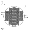
- Fig. 6 shows another embodiment of a field facet mirror 6.
- Components which are equivalent to those explained above with reference to the field facet mirror according to Fig. 4 have the same reference numerals and are only described if they differ from the components of the field facet mirror 6 according to Fig. 4 .
- the field facet mirror according to Fig. 6 has a field facet arrangement with curved field facets 7. These field facets 7 are arranged in a total of five columns with in each case a plurality of field facet groups 8.
- the field facet arrangement is inscribed in a circular boundary of a carrier plate 9a of the field facet mirror.
- the field facets 7 of the embodiment according to Fig. 6 have in each case the same surface area and the same ratio of width (in x-direction) to height (in y-direction), which corresponds to the x/y aspect ratio of the field facets 7 of the embodiment according to Fig. 4 .
- the field intensity setting device 24 has an intensity effect which has virtually no impact on an illumination angle distribution of the object field 19.
- FIG. 7 The Figure schematically illustrates the path of three radiation sub-bundles 28, 29 and 30 from a pupil plane 31, in which is arranged the pupil facet mirror 10, across the field plane 16 up to the reticle plane 17.
- the planes 31, 16 and 17, which are in practice arranged in succession in the light path of the three radiation sub-bundles 28, 29 and 30, are shown next to one another in Fig. 7 for illustrative purposes. The following is based on the idealized assumption that the field facets 7 of the field facet mirror 6 according to Fig. 4 are imaged into the field plane 16 in such a way as to coincide perfectly.
- An edge boundary of the bundle 3 of useful radiation in the field plane 16 therefore has the same extension in both the x-direction and the y-direction as a single image of one of the field facets 7. Consequently, in the event of such a perfect superposition, the bundle 3 of useful radiation has an x/y aspect ratio which is perfectly equal to the x/y aspect ratio of the field facets 7.
- an edge 32 of the bundle 3 of useful radiation facing the individual diaphragms 27 is formed and illuminated by all of the three radiation sub-bundles 28 to 30 at the same time.
- the individual diaphragms 27, which cover the bundle 3 of useful radiation from the edge 32, have exactly the same, in other words an illumination-angle-independent, intensity effect on all radiation sub-bundles 28 to 30.
- this is schematically indicated in the pupil plane 31 on the right-hand side of Fig. 7 by rectangular shadows which are active on one side. These shadows in the pupil plane 31 do not constitute real diaphragms.
- the field facet images in the field facet plane 16 need not coincide perfectly in the x-direction, in other words perpendicular to the scanning direction, for the field intensity setting device 24 to have an illumination-angle-independent effect according to the above description; in fact, the field facet images may very well be arranged at a certain offset with respect to each other. If the field facet images in the field facet plane 16 coincide well even in the x-direction, this may be used for intensity detection by decoupling useful radiation.
- the three radiation sub-bundles 28 to 30 have slightly diverged in particular in the y-direction in such a way that for instance the radiation sub-bundle 28 slightly projects upwardly in the y-direction and beyond the radiation sub-bundle 29 in the center of the object field 19, while the radiation sub-bundle 30 slightly projects beyond the radiation sub-bundle 29 downwardly in the y-direction.
- the reticle sees scan-integrated all of the three radiation sub-bundles 28 to 30 to their full extent; consequently, the mentioned y-offset between the respective radiation sub-bundles 28 to 30 in the reticle plane 17 does not have any negative effects.
- the x/y aspect ratio of the object field 19 is smaller due to the above-described y-offset of the radiation sub-bundles 28 to 30.
- Fig. 8 shows a rectangular field facet 7 of the field facet mirror 6 according to Fig. 4 with an x/y aspect ratio which corresponds to a given x/y aspect ratio in the field plane 16.
- a field facet mirror 6 needs to be used which comprises field facets 33 whose x/y aspect ratio is greater than the x/y aspect ratio of the object field 19. Therefore, a field facet mirror 6 needs to be used in practice whose field facets 33 are narrower in the y-direction (cf. Fig. 9 ).
- a y-extension y 33 of the field facets is thus smaller than a y-extension y 7 of the field facets 7.
- a mutual shadowing of the field facets 7 caused by the illumination geometry of the field facet mirror 10 may result in individually formed images of the field facets 7 in the field plane 16.
- the transmission optics 15 may have different imaging scales for different channels, in other words for different radiation sub-bundles, depending on the respectively observed radiation bundle. Likewise, these different imaging scales also result in a superposition of the radiation bundle in the field plane 16 which deviates from the perfect superposition.
- Another reason for an imperfect superposition in the field plane 16 lies in that due to the grazing incidence mirror 14, the radiation sub-bundles to be superimposed in the field plane 16 may have different curvatures.
- the illumination optics 26 is therefore adjusted in such a way that the individual radiation sub-bundles, which image the respective field facets 7, coincide in the best possible way in the region of the edge 32 facing the individual diaphragms 27.
- This is schematically illustrated in Fig. 10 .
- An imperfect superposition of the radiation sub-bundles at an edge 33a opposite to the edge 33 is acceptable, as it is indicated by the boundaries 34, 35 of individual radiation sub-bundles which deviate from each other in the y-direction.
- the illumination optics needs to be adjusted by tilting in particular the pupil facets 11 in such a way as to minimize the impact of the field intensity setting device 24 on the illumination angles.
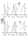
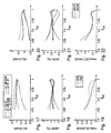
- Figs 11 to 16 show illumination parameters in the object field 19 in the event of a non-optimized superposition of the radiation sub-bundles which is generated by the illumination optics 26, while Figs. 17 to 22 show the same illumination parameters in the event of a correspondingly optimized superposition of the radiation sub-bundles.
- tx and ty are defined as follows:
- centroid beam of a light bundle which is assigned to this field point.
- the centroid beam has the energy-weighted direction of the light bundle which is emitted by this field point.
- the centroid beam of each field point is parallel to the principal beam defined by the illumination optics 26 or the projection optics 20.
- the direction of the centroid beam s 0 (x, y) is known due to the design data of the illumination optics 26 or the projection optics 20.
- the principal beam at a field point is defined by the connection line between the field point and the center of the entrance pupil of the projection optics 20.
- E(u, v, x, y) is the energy distribution for the field point x, y as a function of the pupil coordinates u, v, in other words as a function of the illumination angle seen by the respective field point x, y.
- ⁇ (x, y) ⁇ dudvE ( u, v, x, y ) is the total energy to which the point x, y is exposed.
- a central object field point x 0 , y 0 sees the radiation of partial radiation sub-bundles from directions u, v which are defined by the position of the respective pupil facets 11.
- the centroid beam s extends along the principal beam only if the different energies or intensities, respectively, of the partial radiation sub-bundles, which are assigned to the pupil facets 11, combine to form a centroid beam direction which is integrated over all pupil facets 11 and which is parallel to the principal beam direction. This can be achieved only at ideal circumstances.
- the telecentricity error is corrected which is integrated by a point (x, e.g. x 0 ) on a reticle 18 moving through the object field in the reticle plane 17 during a scanning process, wherein a difference is made between an x-telecentricity error (Tx) and a y-telecentricity error (Ty).
- the y-telecentricity error is defined as deviation of the centroid beam from the principal beam perpendicular to the scanning direction.
- the x-telecentricity error is defined as the deviation of the centroid beam from the principal beam in the scanning direction.
- the ellipticity is another parameter for determining the quality of illumination of the object field 19 in the reticle plane 17.
- the determination of the ellipticity helps to obtain more precise information with regard to the distribution of energy or intensity, respectively, across the entrance pupil of the projection optics 20.
- the entrance pupil is divided into eight octants which are numbered in an anticlockwise direction from O 1 to O 8 , as it is common practice in mathematics.
- the contribution of energy or intensity, respectively, delivered by the octants O 1 to O 8 of the entrance pupil for illuminating a field point is hereinafter referred to as energy or intensity contribution, respectively, I 1 to I 8 .
- E 0 / 90 I 1 + I 8 + I 4 + I 5 I 2 + I 3 + I 6 + I 7 .
- Fig. 11 shows the deviation of an x-telecentricity from an initial value for five different field heights as a function of the amount of intensity which is allowed to pass through by the assigned individual diaphragm 27 at this field height.
- an ellipticity variation ⁇ E90 at a transmission rate of 0.85 varies between 2.5% and -1% compared to a non-attenuated value (cf. Fig. 12 ).
- the value ⁇ E45 reaches a maximum value of -2% or approximately 4.5%, respectively (cf. Fig. 15 ).
- a maximum telecentricity variation reaches a value of 2.5% (cf. Fig. 13 ).
- a maximum ellipticity variation max( ⁇ E) reaches values in the range of 4.5% (cf. Fig. 16 ).
- Figs. 17 to 22 clearly show the impact of the optimized superposition on the radiation sub-bundles in the region of the edge 32 in the field plane 16.
- a maximum telecentricity variation rate of 0.5 is not exceeded at any field height (cf. Fig. 19 ).
- a maximum ellipticity variation rate of 2% is not exceeded at any field height either (cf. Fig. 22 ).
- These maximum variations apply for an attenuation up to a transmission rate of 0.85. If the attenuation reaches a transmission rate of 0.9, the telecentricity variation does not exceed a value of 0.4 mrad and the ellipticity variation does not exceed a value of 1%.
- the edge 32 facing the individual diaphragms 27 of the field intensity setting device 24 is not illuminated by all field facets 7 but by a subgroup of the field facets 7.
- This subgroup of the field facets 7 is selected in such a way that the field facets 7 of the subgroup represent all illumination angles, which are achieved at a given illumination by means of the illumination optics 26, in a preferably equally distributed manner.
- the subgroup of field facets 7 may for instance be formed by in each case one field facet 7 from the field facet group 8.
- the subgroup may in each case include the central field facet mirror 6 or one of the two central field facet mirrors 6 of the respective field facet group 8.
- field facets 7 serving as the selected field facets 8a in the field facet mirror 6 according to Fig. 6 are indicated by means of hatched lines
- the respective field facet, which is selected for the subgroup may for instance be slightly wider in the y-direction than the remaining field facets 7 of the field facet group 8.
- the subgroup field facet may be a field facet 7 according to Fig. 8 and the other field facets 7 of the field facet group 8 may be field facets 7 according to Fig. 9 .
- a subgroup selection may also be achieved by an individual guidance of radiation sub-bundles for the channels which are formed by the field facets 7 of the field facet subgroup; to this end, the pupil facets 11 are tilted correspondingly.
- a region between the edge 32 and a boundary 36 within the bundle 3 of useful radiation is only illuminated by the field facets 7 of the field facet subgroup (cf. Fig 10 ). Seen from the edge 32, the radiation sub-bundles of all other channels are disposed beyond the boundary 36.
- the field facets 7 of the subgroup are selected in such a way as to ensure that the radiation sub-bundles thereof coincide in the best possible way in the field plane 16 near the edge 32.
- the individual diaphragms 27 only have an impact on the intensities of the radiation sub-bundles which are associated with these field facets 7 of the subgroup.
- this alternative embodiment of the coinciding radiation sub-bundles in the field plane 16 also guarantees an illumination-angle-independent effect of the field intensity setting device 24.
- the individual diaphragms 27 may at least in some portions be semipermeable and/or transparent, thus allowing for a selective setting. Adjacent individual diaphragms 27 may partially overlap with each other in the x-direction. In particular in this case, it is advantageous for the individual diaphragms 27 to have a variable transmission across their extension.
- the individual diaphragms 27 may have a structured end side, as it is for example explained in US 2006/0244941 A1 , in particular in Figs. 10 to 12 .
Landscapes
- Physics & Mathematics (AREA)
- General Physics & Mathematics (AREA)
- Exposure And Positioning Against Photoresist Photosensitive Materials (AREA)
- Exposure Of Semiconductors, Excluding Electron Or Ion Beam Exposure (AREA)
- Lenses (AREA)
- Microscoopes, Condenser (AREA)
Claims (15)
- Beleuchtungsoptik (26) für die Mikrolithographie- mit einer optischen Baugruppe (26a) zur Führung von Beleuchtungslicht hin zu einem auszuleuchtenden Objektfeld (19) in einer Objektebene (17),- wobei die Beleuchtungsoptik (26) ein Beleuchtungslicht-Strahlbündel (3) in eine Mehrzahl von Strahlbüschel (28 bis 30) zerlegt, die verschiedenen Beleuchtungswinkeln der Objektfeldbeleuchtung zugeordnet sind,- wobei die Beleuchtungsoptik (26) derart ausgeführt ist, dass zumindest einige der Strahlbüschel (28 bis 30) in einer Überlagerungsebene (16), die von der Objektebene (17) beabstandet ist und die nicht in die Objektebene (17), in der die Überlagening stattfindet, abgebildet ist, so überlagert werden, dass Ränder (32) der überlagerten Strahlbüschel (28 bis 30) zumindest abschnittsweise zusammenfallen.- mit einer in der Überlagerungsebene (16), die dann eine Intensitätsvorgabeebene darstellt, angeordnete Feldintensitäts-Vorgabeeinrichtung (24).
- Beleuchtungsoptik (26) gemäß Anspruch 1, mit einem Feldfacettenspiegel (6) mit einer Mehrzahl von Feldfacetten (7), die in eine Überlagerungsebene (16) derart abgebildet werden, dass Ränder (32) der Bilder der Feldfacetten (7) in der Überlagerungsebene (16) zumindest abschnittsweise zusammenfallen.
- Beleuchtungsoptik nach Anspruch 1 oder 2, dadurch gekennzeichnet, dass die Feldintensitäts-Vorgabeeinrichtung (24) zur Einstellung einer Intensitätsverteilung des Beleuchtungslichts über das Objektfeld (19) dient, wobei die Ränder (32) der überlagerten Strahlbüschel (28 bis 30) dort, wo sie von der Feldintensitäts-Vorgabeeinrichtung (24) beeinflussbar sind, zusammenfallen.
- Beleuchtungsoptik nach Anspruch 3, dadurch gekennzeichnet, dass die Intensitäts-Vorgabeeinrichtung (24) eine Mehrzahl von nebeneinander angeordneten und bei Beaufschlagung mit Beleuchtungslicht dieses zumindest schwächenden Einzelblenden (27) aufweist, die parallel zu einer Objektverlagerungsrichtung (y) in ein Beleuchtungslicht-Strahlbündel (3) hineinverschiebbar sind.
- Beleuchtungsoptik (26) gemäß Anspruch 1,- mit einer Feldintensitäts-Vorgabeeinrichtung (24) zur Einstellung einer Intensitätsverteilung über das Objektfeld (19) mit einer Mehrzahl von nebeneinander angeordneten und bei Beaufschlagung mit Beleuchtungslicht dieses zumindest schwächenden Einzelblenden (27), die parallel zu einer Objektverlagerungsrichtung (y) in ein Beleuchtungslicht-Strahlbündel (3) hineinverschiebbar sind,wobei alle Einzelblenden (27) der Feldintenssitäts-Vorgabeeinrichtung (24) so angeordnet sind, dass sie von ein und derselben Seite her in das Beleuchtungslicht-Strahlbündel (3) einschiebbar sind.
- Beleuchtungsoptik nach einem der Ansprüche 3 bis 5, dadurch gekennzeichnet, dass die Feldintensitäts-Vorgabeeinrichtung (24) in einer Intensitätsvorgabeebene (16) angeordnet ist, die mit einer Feldebene der optischen Baugruppe (26a) zusammenfällt.
- Beleuchtungsoptik nach einem der Ansprüche 1 bis 6, dadurch gekennzeichnet, dass die optische Baugruppe (26a) einen Feldfacettenspiegel (6) mit einer Mehrzahl von Feldfacetten (7) aufweist, deren Bilder im Objektfeld (19) zumindest teilweise überlagert werden.
- Beleuchtungsoptik nach Anspruch 7, dadurch gekennzeichnet, dass die optische Baugruppe (26a) einen Pupillenfacettenspiegel (10) mit einer Mehrzahl von Pupillenfacetten (11) aufweist, die im Lichtweg des Beleuchtungslichts den Feldfacetten (7) zugeordnet sind.
- Beleuchtungsoptik nach einem der Ansprüche 4 bis 8, dadurch gekennzeichnet, dass die Einzelblenden (27) zumindest abschnittsweise zumindest teilweise transparent sind.
- Beleuchtungssystem mit einer Beleuchtungsoptik nach einem der Ansprüche 1 bis 9 und einer Lichtquelle (2).
- Beleuchtungssystem nach Anspruch 10, dadurch gekennzeichnet, dass die Lichtquelle (2) als EUV-Lichtquelle ausgeführt ist.
- Beleuchtungssystem mit einer Beleuchtungsoptik (26) für die Mikrolithographie- mit einer optischen Baugruppe (26a) zur Führung von Beleuchtungslicht hin zu einem auszuleuchtenden Objektfeld (19) in einer Objektebene (17),- wobei die Beleuchtungsoptik (26) ein Beleuchtungslicht-Strahlbündel (3) in eine Mehrzahl von Strahlbüschel (28 bis 30) zerlegt, die verschiedenen Beleuchtungswinkeln der Objektfeldbeleuchtung zugeordnet sind,- wobei die Beleuchtungsoptik (26) derart ausgeführt ist, dass zumindest einige der Strahlbüschel (28 bis 30) in einer Überlagerungsebene (16), die von der Objektebene (17) beabstandet ist und die nicht in die Objektebene (17), in der die Überlagerung stattfindet, abgebildet ist, so überlagert werden, dass Ränder (32) der überlagerten Strahlbüschel (28 bis 30) zumindest abschnittsweise zusammenfallen.- wobei das Beleuchtungssystem ferner ein Projektionsobjektiv (20) zur Abbildung des Objektfeldes in eine Bildebene (21) umfasst.
- Projektionsbelichtungsanlage (1) mit einem Beleuchtungssystem gemäß Anspruch 12, ferner umfassend eine Lichtquelle (2).
- Projektionsbelichtungsanlage (1)- mit einem Beleuchtungssystem nach Anspruch 10 oder 11,- mit einem Projektionsobjektiv (20) zur Abbildung des Objektfeldes (19) in eine Bildebene (21).
- Verfahren zur Herstellung strukturierter Bauelemente mit folgenden Schritten:- Bereitstellen eines Wafers (23), auf dem zumindest teilweise eine Schicht aus einem lichtempfindlichen Material aufgebracht ist,- Bereitstellen eines Retikels (18), das abzubildende Strukturen aufweist,- Bereitstellen einer Projektionsbelichtungsanlage (1) nach Anspruch 13 oder 14,- Projizieren wenigstens eines Teils des Retikels (18) auf einen Bereich der Schicht des Wafers (23) mit Hilfe der Projektionsbelichtungsanlage (1).
Applications Claiming Priority (3)
| Application Number | Priority Date | Filing Date | Title |
|---|---|---|---|
| US1281207P | 2007-12-11 | 2007-12-11 | |
| DE102008013229.2A DE102008013229B4 (de) | 2007-12-11 | 2008-03-07 | Beleuchtungsoptik für die Mikrolithographie |
| PCT/EP2008/009786 WO2009074211A1 (en) | 2007-12-11 | 2008-11-20 | Illumination optics for microlithography |
Publications (2)
| Publication Number | Publication Date |
|---|---|
| EP2240830A1 EP2240830A1 (de) | 2010-10-20 |
| EP2240830B1 true EP2240830B1 (de) | 2015-04-01 |
Family
ID=40680146
Family Applications (1)
| Application Number | Title | Priority Date | Filing Date |
|---|---|---|---|
| EP08859710.9A Active EP2240830B1 (de) | 2007-12-11 | 2008-11-20 | Beleuchtungsoptik für die mikrolithografie |
Country Status (8)
| Country | Link |
|---|---|
| US (1) | US8937708B2 (de) |
| EP (1) | EP2240830B1 (de) |
| JP (2) | JP5548135B2 (de) |
| KR (1) | KR101517645B1 (de) |
| CN (2) | CN101896869B (de) |
| DE (1) | DE102008013229B4 (de) |
| TW (1) | TWI474125B (de) |
| WO (1) | WO2009074211A1 (de) |
Cited By (1)
| Publication number | Priority date | Publication date | Assignee | Title |
|---|---|---|---|---|
| DE102015209453A1 (de) | 2015-05-22 | 2016-11-24 | Carl Zeiss Smt Gmbh | Pupillenfacettenspiegel |
Families Citing this family (19)
| Publication number | Priority date | Publication date | Assignee | Title |
|---|---|---|---|---|
| DE102008042462B4 (de) | 2008-09-30 | 2010-11-04 | Carl Zeiss Smt Ag | Beleuchtungssystem für die EUV-Mikrolithographie |
| JP5134732B2 (ja) * | 2008-10-31 | 2013-01-30 | カール・ツァイス・エスエムティー・ゲーエムベーハー | Euvマイクロリソグラフィ用の照明光学系 |
| DE202009004769U1 (de) | 2009-01-19 | 2010-06-17 | Paul Hettich Gmbh & Co. Kg | Auszugsführung |
| DE102010001388A1 (de) | 2010-01-29 | 2011-08-04 | Carl Zeiss SMT GmbH, 73447 | Facettenspiegel zum Einsatz in der Mikrolithografie |
| DE102010062779A1 (de) | 2010-12-10 | 2012-06-14 | Carl Zeiss Smt Gmbh | Beleuchtungsoptik für die Projektionslithographie |
| WO2012089224A1 (en) * | 2010-12-28 | 2012-07-05 | Carl Zeiss Smt Gmbh | Illumination system of a microlithographic projection exposure apparatus |
| DE102011005881A1 (de) | 2011-03-22 | 2012-05-03 | Carl Zeiss Smt Gmbh | Verfahren zur Einstellung eines Beleuchtungssystems einer Projektionsbelichtungsanlage für die Projektionslithographie |
| NL2008322A (en) | 2011-04-13 | 2012-10-16 | Asml Holding Nv | Double euv illumination uniformity correction system and method. |
| DE102011076297A1 (de) | 2011-05-23 | 2012-11-29 | Carl Zeiss Smt Gmbh | Blende |
| DE102012205886A1 (de) | 2012-04-11 | 2013-10-17 | Carl Zeiss Smt Gmbh | Beleuchtungsintensitäts-Korrekturvorrichtung zur Vorgabe einer Beleuchtungsintensität über ein Beleuchtungsfeld einer lithographischen Projektionsbelichtungsanlage |
| DE102012208016A1 (de) * | 2012-05-14 | 2013-05-08 | Carl Zeiss Smt Gmbh | Beleuchtungsoptik für die Mikrolithographie |
| DE102012212664A1 (de) * | 2012-07-19 | 2014-01-23 | Carl Zeiss Smt Gmbh | Verfahren zum Einstellen eines Beleuchtungssettings |
| DE102017220265A1 (de) | 2017-11-14 | 2019-05-16 | Carl Zeiss Smt Gmbh | Beleuchtungsintensitäts-Korrekturvorrichtung zur Vorgabe einer Beleuchtungsintensität über ein Beleuchtungsfeld einer lithographischen Projektionsbelichtungsanlage |
| DE102018201009A1 (de) * | 2018-01-23 | 2019-07-25 | Carl Zeiss Smt Gmbh | Beleuchtungsoptik für die Projektionslithographie |
| DE102018208710A1 (de) | 2018-06-04 | 2019-12-05 | Carl Zeiss Smt Gmbh | Blende zur Anordnung in einer Engstelle eines EUV-Beleuchtungsbündels |
| DE102018215505A1 (de) | 2018-09-12 | 2018-10-31 | Carl Zeiss Smt Gmbh | Projektionsoptik für eine Projektionsbelichtungsanlage |
| DE102018217707A1 (de) | 2018-10-16 | 2018-12-27 | Carl Zeiss Smt Gmbh | Feldfacettenspiegel zum Einsatz in einer Beleuchtungsoptik einer Projektionsbelichtungsanlage für die EUV-Projektonslithographie |
| DE102019206869A1 (de) | 2019-05-13 | 2019-08-08 | Carl Zeiss Smt Gmbh | Strahlungsquellen-Modul |
| KR20230167934A (ko) | 2022-06-03 | 2023-12-12 | 삼성전자주식회사 | 극자외선 노광 장치 및 그것의 동작 방법 |
Citations (1)
| Publication number | Priority date | Publication date | Assignee | Title |
|---|---|---|---|---|
| EP1555573A2 (de) * | 2003-12-31 | 2005-07-20 | ASML Netherlands BV | Optischer Abschwächer, Strahlsystem, damit ausgerüsteter lithographischer Apparat und Methode zur Herstellung einer Vorrichtung |
Family Cites Families (25)
| Publication number | Priority date | Publication date | Assignee | Title |
|---|---|---|---|---|
| JP3057998B2 (ja) * | 1994-02-16 | 2000-07-04 | キヤノン株式会社 | 照明装置及びそれを用いた投影露光装置 |
| JPH1039227A (ja) * | 1996-07-29 | 1998-02-13 | Olympus Optical Co Ltd | 遮光装置及び光学顕微鏡 |
| US6013401A (en) * | 1997-03-31 | 2000-01-11 | Svg Lithography Systems, Inc. | Method of controlling illumination field to reduce line width variation |
| DE10053587A1 (de) * | 2000-10-27 | 2002-05-02 | Zeiss Carl | Beleuchtungssystem mit variabler Einstellung der Ausleuchtung |
| DE10100265A1 (de) * | 2001-01-08 | 2002-07-11 | Zeiss Carl | Beleuchtungssystem mit Rasterelementen unterschiedlicher Größe |
| EP0955641B1 (de) * | 1998-05-05 | 2004-04-28 | Carl Zeiss | Beleuchtungssystem insbesondere für die EUV-Lithographie |
| US6476905B1 (en) * | 2000-01-20 | 2002-11-05 | Taiwan Semiconductor Manufacturing Co., Ltd. | Step and scan exposure system equipped with a plurality of attenuator blades for exposure control |
| JP2002156280A (ja) * | 2000-08-15 | 2002-05-31 | Nikon Corp | 照度計測装置、露光装置、及び露光方法 |
| JP2002110529A (ja) * | 2000-10-03 | 2002-04-12 | Nikon Corp | 投影露光装置及び該装置を用いたマイクロデバイス製造方法 |
| EP1291721B1 (de) | 2001-09-07 | 2008-02-27 | ASML Netherlands B.V. | Lithographischer Apparat und Verfahren zur Herstellung einer Vorrichtung |
| DE60225216T2 (de) * | 2001-09-07 | 2009-03-05 | Asml Netherlands B.V. | Lithographischer Apparat und Verfahren zur Herstellung einer Vorrichtung |
| US7170587B2 (en) * | 2002-03-18 | 2007-01-30 | Asml Netherlands B.V. | Lithographic apparatus and device manufacturing method |
| JP4099423B2 (ja) * | 2002-03-18 | 2008-06-11 | エーエスエムエル ネザーランズ ビー.ブイ. | リソグラフィ装置およびデバイス製造法 |
| JP3720788B2 (ja) * | 2002-04-15 | 2005-11-30 | キヤノン株式会社 | 投影露光装置及びデバイス製造方法 |
| DE10219514A1 (de) | 2002-04-30 | 2003-11-13 | Zeiss Carl Smt Ag | Beleuchtungssystem, insbesondere für die EUV-Lithographie |
| WO2005040927A2 (en) | 2003-10-18 | 2005-05-06 | Carl Zeiss Smt Ag | Device and method for illumination dose adjustments in microlithography |
| US7023524B2 (en) * | 2003-12-18 | 2006-04-04 | Asml Netherlands B.V. | Lithographic apparatus and device manufacturing method |
| DE102004002415B4 (de) | 2004-01-16 | 2008-07-10 | Metzeler Automotive Profile Systems Gmbh | Vorrichtung zum Steuern und Überwachen eines bewegbaren Schliesselements, insbesondere einer elektrisch angetriebenen Fensterscheibe eines Kraftfahrzeugs |
| US20060103828A1 (en) * | 2004-11-17 | 2006-05-18 | David Douglas J | Adjustable illumination blade assembly for photolithography scanners |
| US7088527B2 (en) * | 2004-12-28 | 2006-08-08 | Asml Holding N.V. | Uniformity correction system having light leak and shadow compensation |
| CN1645258A (zh) * | 2005-01-24 | 2005-07-27 | 中国科学院光电技术研究所 | 高数值孔径光刻成像偏振控制装置 |
| JP2006253487A (ja) * | 2005-03-11 | 2006-09-21 | Nikon Corp | 照明装置、投影露光方法、投影露光装置、及びマイクロデバイスの製造方法 |
| DE102006017336B4 (de) * | 2006-04-11 | 2011-07-28 | Carl Zeiss SMT GmbH, 73447 | Beleuchtungssystem mit Zoomobjektiv |
| JP4797764B2 (ja) * | 2006-04-14 | 2011-10-19 | 株式会社ニコン | 露光装置の較正方法及び露光装置 |
| NL1036162A1 (nl) * | 2007-11-28 | 2009-06-02 | Asml Netherlands Bv | Lithographic apparatus and method. |
-
2008
- 2008-03-07 DE DE102008013229.2A patent/DE102008013229B4/de active Active
- 2008-11-20 WO PCT/EP2008/009786 patent/WO2009074211A1/en active Application Filing
- 2008-11-20 KR KR1020107014669A patent/KR101517645B1/ko active IP Right Grant
- 2008-11-20 CN CN200880120429.7A patent/CN101896869B/zh active Active
- 2008-11-20 EP EP08859710.9A patent/EP2240830B1/de active Active
- 2008-11-20 CN CN201410006090.5A patent/CN103713474B/zh active Active
- 2008-11-20 JP JP2010537272A patent/JP5548135B2/ja active Active
- 2008-12-10 TW TW97147987A patent/TWI474125B/zh active
-
2010
- 2010-05-28 US US12/789,772 patent/US8937708B2/en active Active
-
2014
- 2014-05-16 JP JP2014102463A patent/JP5888622B2/ja active Active
Patent Citations (1)
| Publication number | Priority date | Publication date | Assignee | Title |
|---|---|---|---|---|
| EP1555573A2 (de) * | 2003-12-31 | 2005-07-20 | ASML Netherlands BV | Optischer Abschwächer, Strahlsystem, damit ausgerüsteter lithographischer Apparat und Methode zur Herstellung einer Vorrichtung |
Cited By (2)
| Publication number | Priority date | Publication date | Assignee | Title |
|---|---|---|---|---|
| DE102015209453A1 (de) | 2015-05-22 | 2016-11-24 | Carl Zeiss Smt Gmbh | Pupillenfacettenspiegel |
| WO2016188810A1 (en) | 2015-05-22 | 2016-12-01 | Carl Zeiss Smt Gmbh | Pupil facet mirror |
Also Published As
| Publication number | Publication date |
|---|---|
| DE102008013229B4 (de) | 2015-04-09 |
| EP2240830A1 (de) | 2010-10-20 |
| CN101896869A (zh) | 2010-11-24 |
| KR101517645B1 (ko) | 2015-05-04 |
| DE102008013229A1 (de) | 2009-06-18 |
| CN103713474A (zh) | 2014-04-09 |
| JP2011507241A (ja) | 2011-03-03 |
| JP2014179645A (ja) | 2014-09-25 |
| TW200941149A (en) | 2009-10-01 |
| US8937708B2 (en) | 2015-01-20 |
| KR20100110316A (ko) | 2010-10-12 |
| TWI474125B (zh) | 2015-02-21 |
| JP5888622B2 (ja) | 2016-03-22 |
| US20100253926A1 (en) | 2010-10-07 |
| JP5548135B2 (ja) | 2014-07-16 |
| CN101896869B (zh) | 2014-02-26 |
| CN103713474B (zh) | 2016-06-01 |
| WO2009074211A1 (en) | 2009-06-18 |
Similar Documents
| Publication | Publication Date | Title |
|---|---|---|
| EP2240830B1 (de) | Beleuchtungsoptik für die mikrolithografie | |
| US7969556B2 (en) | Illumination optical system for microlithography and illumination system and projection exposure system with an illumination optical system of this type | |
| US8593645B2 (en) | Microlithographic projection exposure apparatus and related method | |
| KR101542272B1 (ko) | 결상 광학 시스템 및 이러한 유형의 결상 광학 시스템을 구비하는 마이크로리소그래피용 투영 노광 장치 | |
| KR101515663B1 (ko) | 결상 광학 시스템 및 이러한 유형의 결상 광학 시스템을 갖는 마이크로리소그래피용 투영 노광 장치 | |
| US9176390B2 (en) | Method for adjusting an illumination system of a projection exposure apparatus for projection lithography | |
| US8164046B2 (en) | Illumination system for illuminating a mask in a microlithographic projection exposure apparatus | |
| KR101388330B1 (ko) | 이미징 광학기기 및 이러한 유형의 이미징 광학기기를 갖는 마이크로리소그래피용 투영 노광 설비 | |
| US9201226B2 (en) | Imaging optics | |
| CN102349026A (zh) | 微光刻投射曝光设备 | |
| WO2013178432A1 (en) | Illumination optical unit for projection lithography | |
| US8854605B2 (en) | Illumination optical system, exposure apparatus, and device fabrication method | |
| WO2014063719A1 (en) | Illumination system of a microliteographic projection exposure apparatus | |
| WO2010112328A1 (en) | Imaging optics and projection exposure installation for microlithography with an imaging optics of this type | |
| EP2715452B1 (de) | Optische bildgebungseinheit | |
| US9110378B2 (en) | Illumination optical system for projection lithography | |
| WO2016188810A1 (en) | Pupil facet mirror | |
| WO2024056600A1 (en) | Method to adjust an illumination beam path within an illumination optics and illumination optics having an adjustment system |
Legal Events
| Date | Code | Title | Description |
|---|---|---|---|
| PUAI | Public reference made under article 153(3) epc to a published international application that has entered the european phase |
Free format text: ORIGINAL CODE: 0009012 |
|
| 17P | Request for examination filed |
Effective date: 20100607 |
|
| AK | Designated contracting states |
Kind code of ref document: A1 Designated state(s): AT BE BG CH CY CZ DE DK EE ES FI FR GB GR HR HU IE IS IT LI LT LU LV MC MT NL NO PL PT RO SE SI SK TR |
|
| AX | Request for extension of the european patent |
Extension state: AL BA MK RS |
|
| 17Q | First examination report despatched |
Effective date: 20101117 |
|
| RAP1 | Party data changed (applicant data changed or rights of an application transferred) |
Owner name: CARL ZEISS SMT GMBH |
|
| DAX | Request for extension of the european patent (deleted) | ||
| GRAP | Despatch of communication of intention to grant a patent |
Free format text: ORIGINAL CODE: EPIDOSNIGR1 |
|
| INTG | Intention to grant announced |
Effective date: 20141120 |
|
| GRAS | Grant fee paid |
Free format text: ORIGINAL CODE: EPIDOSNIGR3 |
|
| GRAA | (expected) grant |
Free format text: ORIGINAL CODE: 0009210 |
|
| AK | Designated contracting states |
Kind code of ref document: B1 Designated state(s): AT BE BG CH CY CZ DE DK EE ES FI FR GB GR HR HU IE IS IT LI LT LU LV MC MT NL NO PL PT RO SE SI SK TR |
|
| REG | Reference to a national code |
Ref country code: GB Ref legal event code: FG4D |
|
| REG | Reference to a national code |
Ref country code: CH Ref legal event code: EP Ref country code: NL Ref legal event code: T3 |
|
| REG | Reference to a national code |
Ref country code: NL Ref legal event code: T3 Ref country code: IE Ref legal event code: FG4D |
|
| REG | Reference to a national code |
Ref country code: NL Ref legal event code: T3 |
|
| REG | Reference to a national code |
Ref country code: AT Ref legal event code: REF Ref document number: 719417 Country of ref document: AT Kind code of ref document: T Effective date: 20150515 |
|
| REG | Reference to a national code |
Ref country code: DE Ref legal event code: R096 Ref document number: 602008037469 Country of ref document: DE Effective date: 20150521 |
|
| REG | Reference to a national code |
Ref country code: AT Ref legal event code: MK05 Ref document number: 719417 Country of ref document: AT Kind code of ref document: T Effective date: 20150401 |
|
| REG | Reference to a national code |
Ref country code: LT Ref legal event code: MG4D |
|
| PG25 | Lapsed in a contracting state [announced via postgrant information from national office to epo] |
Ref country code: CZ Free format text: LAPSE BECAUSE OF FAILURE TO SUBMIT A TRANSLATION OF THE DESCRIPTION OR TO PAY THE FEE WITHIN THE PRESCRIBED TIME-LIMIT Effective date: 20150401 Ref country code: ES Free format text: LAPSE BECAUSE OF FAILURE TO SUBMIT A TRANSLATION OF THE DESCRIPTION OR TO PAY THE FEE WITHIN THE PRESCRIBED TIME-LIMIT Effective date: 20150401 Ref country code: PT Free format text: LAPSE BECAUSE OF FAILURE TO SUBMIT A TRANSLATION OF THE DESCRIPTION OR TO PAY THE FEE WITHIN THE PRESCRIBED TIME-LIMIT Effective date: 20150803 Ref country code: LT Free format text: LAPSE BECAUSE OF FAILURE TO SUBMIT A TRANSLATION OF THE DESCRIPTION OR TO PAY THE FEE WITHIN THE PRESCRIBED TIME-LIMIT Effective date: 20150401 Ref country code: NO Free format text: LAPSE BECAUSE OF FAILURE TO SUBMIT A TRANSLATION OF THE DESCRIPTION OR TO PAY THE FEE WITHIN THE PRESCRIBED TIME-LIMIT Effective date: 20150701 Ref country code: HR Free format text: LAPSE BECAUSE OF FAILURE TO SUBMIT A TRANSLATION OF THE DESCRIPTION OR TO PAY THE FEE WITHIN THE PRESCRIBED TIME-LIMIT Effective date: 20150401 Ref country code: FI Free format text: LAPSE BECAUSE OF FAILURE TO SUBMIT A TRANSLATION OF THE DESCRIPTION OR TO PAY THE FEE WITHIN THE PRESCRIBED TIME-LIMIT Effective date: 20150401 |
|
| PG25 | Lapsed in a contracting state [announced via postgrant information from national office to epo] |
Ref country code: AT Free format text: LAPSE BECAUSE OF FAILURE TO SUBMIT A TRANSLATION OF THE DESCRIPTION OR TO PAY THE FEE WITHIN THE PRESCRIBED TIME-LIMIT Effective date: 20150401 Ref country code: GR Free format text: LAPSE BECAUSE OF FAILURE TO SUBMIT A TRANSLATION OF THE DESCRIPTION OR TO PAY THE FEE WITHIN THE PRESCRIBED TIME-LIMIT Effective date: 20150702 Ref country code: IS Free format text: LAPSE BECAUSE OF FAILURE TO SUBMIT A TRANSLATION OF THE DESCRIPTION OR TO PAY THE FEE WITHIN THE PRESCRIBED TIME-LIMIT Effective date: 20150801 Ref country code: LV Free format text: LAPSE BECAUSE OF FAILURE TO SUBMIT A TRANSLATION OF THE DESCRIPTION OR TO PAY THE FEE WITHIN THE PRESCRIBED TIME-LIMIT Effective date: 20150401 |
|
| REG | Reference to a national code |
Ref country code: DE Ref legal event code: R097 Ref document number: 602008037469 Country of ref document: DE |
|
| PG25 | Lapsed in a contracting state [announced via postgrant information from national office to epo] |
Ref country code: EE Free format text: LAPSE BECAUSE OF FAILURE TO SUBMIT A TRANSLATION OF THE DESCRIPTION OR TO PAY THE FEE WITHIN THE PRESCRIBED TIME-LIMIT Effective date: 20150401 Ref country code: DK Free format text: LAPSE BECAUSE OF FAILURE TO SUBMIT A TRANSLATION OF THE DESCRIPTION OR TO PAY THE FEE WITHIN THE PRESCRIBED TIME-LIMIT Effective date: 20150401 |
|
| PLBE | No opposition filed within time limit |
Free format text: ORIGINAL CODE: 0009261 |
|
| STAA | Information on the status of an ep patent application or granted ep patent |
Free format text: STATUS: NO OPPOSITION FILED WITHIN TIME LIMIT |
|
| PG25 | Lapsed in a contracting state [announced via postgrant information from national office to epo] |
Ref country code: SK Free format text: LAPSE BECAUSE OF FAILURE TO SUBMIT A TRANSLATION OF THE DESCRIPTION OR TO PAY THE FEE WITHIN THE PRESCRIBED TIME-LIMIT Effective date: 20150401 Ref country code: PL Free format text: LAPSE BECAUSE OF FAILURE TO SUBMIT A TRANSLATION OF THE DESCRIPTION OR TO PAY THE FEE WITHIN THE PRESCRIBED TIME-LIMIT Effective date: 20150401 Ref country code: RO Free format text: LAPSE BECAUSE OF NON-PAYMENT OF DUE FEES Effective date: 20150401 |
|
| 26N | No opposition filed |
Effective date: 20160105 |
|
| PG25 | Lapsed in a contracting state [announced via postgrant information from national office to epo] |
Ref country code: IT Free format text: LAPSE BECAUSE OF FAILURE TO SUBMIT A TRANSLATION OF THE DESCRIPTION OR TO PAY THE FEE WITHIN THE PRESCRIBED TIME-LIMIT Effective date: 20150401 |
|
| PG25 | Lapsed in a contracting state [announced via postgrant information from national office to epo] |
Ref country code: SI Free format text: LAPSE BECAUSE OF FAILURE TO SUBMIT A TRANSLATION OF THE DESCRIPTION OR TO PAY THE FEE WITHIN THE PRESCRIBED TIME-LIMIT Effective date: 20150401 |
|
| PG25 | Lapsed in a contracting state [announced via postgrant information from national office to epo] |
Ref country code: LU Free format text: LAPSE BECAUSE OF FAILURE TO SUBMIT A TRANSLATION OF THE DESCRIPTION OR TO PAY THE FEE WITHIN THE PRESCRIBED TIME-LIMIT Effective date: 20151120 Ref country code: MC Free format text: LAPSE BECAUSE OF FAILURE TO SUBMIT A TRANSLATION OF THE DESCRIPTION OR TO PAY THE FEE WITHIN THE PRESCRIBED TIME-LIMIT Effective date: 20150401 |
|
| REG | Reference to a national code |
Ref country code: CH Ref legal event code: PL |
|
| GBPC | Gb: european patent ceased through non-payment of renewal fee |
Effective date: 20151120 |
|
| PG25 | Lapsed in a contracting state [announced via postgrant information from national office to epo] |
Ref country code: CH Free format text: LAPSE BECAUSE OF NON-PAYMENT OF DUE FEES Effective date: 20151130 Ref country code: LI Free format text: LAPSE BECAUSE OF NON-PAYMENT OF DUE FEES Effective date: 20151130 |
|
| REG | Reference to a national code |
Ref country code: IE Ref legal event code: MM4A |
|
| REG | Reference to a national code |
Ref country code: FR Ref legal event code: ST Effective date: 20160729 |
|
| PG25 | Lapsed in a contracting state [announced via postgrant information from national office to epo] |
Ref country code: BE Free format text: LAPSE BECAUSE OF FAILURE TO SUBMIT A TRANSLATION OF THE DESCRIPTION OR TO PAY THE FEE WITHIN THE PRESCRIBED TIME-LIMIT Effective date: 20150401 |
|
| PG25 | Lapsed in a contracting state [announced via postgrant information from national office to epo] |
Ref country code: IE Free format text: LAPSE BECAUSE OF NON-PAYMENT OF DUE FEES Effective date: 20151120 Ref country code: GB Free format text: LAPSE BECAUSE OF NON-PAYMENT OF DUE FEES Effective date: 20151120 |
|
| PG25 | Lapsed in a contracting state [announced via postgrant information from national office to epo] |
Ref country code: FR Free format text: LAPSE BECAUSE OF NON-PAYMENT OF DUE FEES Effective date: 20151130 |
|
| PG25 | Lapsed in a contracting state [announced via postgrant information from national office to epo] |
Ref country code: HU Free format text: LAPSE BECAUSE OF FAILURE TO SUBMIT A TRANSLATION OF THE DESCRIPTION OR TO PAY THE FEE WITHIN THE PRESCRIBED TIME-LIMIT; INVALID AB INITIO Effective date: 20081120 Ref country code: BG Free format text: LAPSE BECAUSE OF FAILURE TO SUBMIT A TRANSLATION OF THE DESCRIPTION OR TO PAY THE FEE WITHIN THE PRESCRIBED TIME-LIMIT Effective date: 20150401 |
|
| PG25 | Lapsed in a contracting state [announced via postgrant information from national office to epo] |
Ref country code: SE Free format text: LAPSE BECAUSE OF FAILURE TO SUBMIT A TRANSLATION OF THE DESCRIPTION OR TO PAY THE FEE WITHIN THE PRESCRIBED TIME-LIMIT Effective date: 20150401 Ref country code: CY Free format text: LAPSE BECAUSE OF FAILURE TO SUBMIT A TRANSLATION OF THE DESCRIPTION OR TO PAY THE FEE WITHIN THE PRESCRIBED TIME-LIMIT Effective date: 20150401 |
|
| PG25 | Lapsed in a contracting state [announced via postgrant information from national office to epo] |
Ref country code: MT Free format text: LAPSE BECAUSE OF FAILURE TO SUBMIT A TRANSLATION OF THE DESCRIPTION OR TO PAY THE FEE WITHIN THE PRESCRIBED TIME-LIMIT Effective date: 20150401 Ref country code: TR Free format text: LAPSE BECAUSE OF FAILURE TO SUBMIT A TRANSLATION OF THE DESCRIPTION OR TO PAY THE FEE WITHIN THE PRESCRIBED TIME-LIMIT Effective date: 20150401 |
|
| P01 | Opt-out of the competence of the unified patent court (upc) registered |
Effective date: 20230525 |
|
| PGFP | Annual fee paid to national office [announced via postgrant information from national office to epo] |
Ref country code: NL Payment date: 20231120 Year of fee payment: 16 |
|
| PGFP | Annual fee paid to national office [announced via postgrant information from national office to epo] |
Ref country code: DE Payment date: 20231121 Year of fee payment: 16 |