EP2240698B1 - Magnetventilanordnung - Google Patents
Magnetventilanordnung Download PDFInfo
- Publication number
- EP2240698B1 EP2240698B1 EP08780365A EP08780365A EP2240698B1 EP 2240698 B1 EP2240698 B1 EP 2240698B1 EP 08780365 A EP08780365 A EP 08780365A EP 08780365 A EP08780365 A EP 08780365A EP 2240698 B1 EP2240698 B1 EP 2240698B1
- Authority
- EP
- European Patent Office
- Prior art keywords
- ports
- spool
- fluid communication
- actuator
- solenoid valve
- Prior art date
- Legal status (The legal status is an assumption and is not a legal conclusion. Google has not performed a legal analysis and makes no representation as to the accuracy of the status listed.)
- Not-in-force
Links
- 239000012530 fluid Substances 0.000 claims abstract description 154
- 238000004891 communication Methods 0.000 claims abstract description 105
- 230000008878 coupling Effects 0.000 description 6
- 238000010168 coupling process Methods 0.000 description 6
- 238000005859 coupling reaction Methods 0.000 description 6
- 230000006835 compression Effects 0.000 description 3
- 238000007906 compression Methods 0.000 description 3
- 238000012986 modification Methods 0.000 description 3
- 230000004048 modification Effects 0.000 description 3
- 238000013459 approach Methods 0.000 description 2
- 230000000712 assembly Effects 0.000 description 2
- 238000000429 assembly Methods 0.000 description 2
- 238000007789 sealing Methods 0.000 description 2
- XEEYBQQBJWHFJM-UHFFFAOYSA-N Iron Chemical group [Fe] XEEYBQQBJWHFJM-UHFFFAOYSA-N 0.000 description 1
- 238000002955 isolation Methods 0.000 description 1
- 239000007788 liquid Substances 0.000 description 1
- 230000007246 mechanism Effects 0.000 description 1
- 230000007704 transition Effects 0.000 description 1
Images


Classifications
-
- F—MECHANICAL ENGINEERING; LIGHTING; HEATING; WEAPONS; BLASTING
- F15—FLUID-PRESSURE ACTUATORS; HYDRAULICS OR PNEUMATICS IN GENERAL
- F15B—SYSTEMS ACTING BY MEANS OF FLUIDS IN GENERAL; FLUID-PRESSURE ACTUATORS, e.g. SERVOMOTORS; DETAILS OF FLUID-PRESSURE SYSTEMS, NOT OTHERWISE PROVIDED FOR
- F15B13/00—Details of servomotor systems ; Valves for servomotor systems
- F15B13/02—Fluid distribution or supply devices characterised by their adaptation to the control of servomotors
- F15B13/04—Fluid distribution or supply devices characterised by their adaptation to the control of servomotors for use with a single servomotor
- F15B13/0401—Valve members; Fluid interconnections therefor
- F15B13/0402—Valve members; Fluid interconnections therefor for linearly sliding valves, e.g. spool valves
-
- F—MECHANICAL ENGINEERING; LIGHTING; HEATING; WEAPONS; BLASTING
- F16—ENGINEERING ELEMENTS AND UNITS; GENERAL MEASURES FOR PRODUCING AND MAINTAINING EFFECTIVE FUNCTIONING OF MACHINES OR INSTALLATIONS; THERMAL INSULATION IN GENERAL
- F16K—VALVES; TAPS; COCKS; ACTUATING-FLOATS; DEVICES FOR VENTING OR AERATING
- F16K31/00—Actuating devices; Operating means; Releasing devices
- F16K31/02—Actuating devices; Operating means; Releasing devices electric; magnetic
- F16K31/06—Actuating devices; Operating means; Releasing devices electric; magnetic using a magnet, e.g. diaphragm valves, cutting off by means of a liquid
- F16K31/0603—Multiple-way valves
- F16K31/061—Sliding valves
- F16K31/0613—Sliding valves with cylindrical slides
-
- F—MECHANICAL ENGINEERING; LIGHTING; HEATING; WEAPONS; BLASTING
- F15—FLUID-PRESSURE ACTUATORS; HYDRAULICS OR PNEUMATICS IN GENERAL
- F15B—SYSTEMS ACTING BY MEANS OF FLUIDS IN GENERAL; FLUID-PRESSURE ACTUATORS, e.g. SERVOMOTORS; DETAILS OF FLUID-PRESSURE SYSTEMS, NOT OTHERWISE PROVIDED FOR
- F15B11/00—Servomotor systems without provision for follow-up action; Circuits therefor
- F15B11/02—Systems essentially incorporating special features for controlling the speed or actuating force of an output member
- F15B11/024—Systems essentially incorporating special features for controlling the speed or actuating force of an output member by means of differential connection of the servomotor lines, e.g. regenerative circuits
-
- F—MECHANICAL ENGINEERING; LIGHTING; HEATING; WEAPONS; BLASTING
- F15—FLUID-PRESSURE ACTUATORS; HYDRAULICS OR PNEUMATICS IN GENERAL
- F15B—SYSTEMS ACTING BY MEANS OF FLUIDS IN GENERAL; FLUID-PRESSURE ACTUATORS, e.g. SERVOMOTORS; DETAILS OF FLUID-PRESSURE SYSTEMS, NOT OTHERWISE PROVIDED FOR
- F15B13/00—Details of servomotor systems ; Valves for servomotor systems
- F15B13/02—Fluid distribution or supply devices characterised by their adaptation to the control of servomotors
- F15B13/04—Fluid distribution or supply devices characterised by their adaptation to the control of servomotors for use with a single servomotor
- F15B13/042—Fluid distribution or supply devices characterised by their adaptation to the control of servomotors for use with a single servomotor operated by fluid pressure
-
- F—MECHANICAL ENGINEERING; LIGHTING; HEATING; WEAPONS; BLASTING
- F16—ENGINEERING ELEMENTS AND UNITS; GENERAL MEASURES FOR PRODUCING AND MAINTAINING EFFECTIVE FUNCTIONING OF MACHINES OR INSTALLATIONS; THERMAL INSULATION IN GENERAL
- F16K—VALVES; TAPS; COCKS; ACTUATING-FLOATS; DEVICES FOR VENTING OR AERATING
- F16K11/00—Multiple-way valves, e.g. mixing valves; Pipe fittings incorporating such valves
- F16K11/02—Multiple-way valves, e.g. mixing valves; Pipe fittings incorporating such valves with all movable sealing faces moving as one unit
- F16K11/06—Multiple-way valves, e.g. mixing valves; Pipe fittings incorporating such valves with all movable sealing faces moving as one unit comprising only sliding valves, i.e. sliding closure elements
- F16K11/065—Multiple-way valves, e.g. mixing valves; Pipe fittings incorporating such valves with all movable sealing faces moving as one unit comprising only sliding valves, i.e. sliding closure elements with linearly sliding closure members
- F16K11/07—Multiple-way valves, e.g. mixing valves; Pipe fittings incorporating such valves with all movable sealing faces moving as one unit comprising only sliding valves, i.e. sliding closure elements with linearly sliding closure members with cylindrical slides
-
- F—MECHANICAL ENGINEERING; LIGHTING; HEATING; WEAPONS; BLASTING
- F16—ENGINEERING ELEMENTS AND UNITS; GENERAL MEASURES FOR PRODUCING AND MAINTAINING EFFECTIVE FUNCTIONING OF MACHINES OR INSTALLATIONS; THERMAL INSULATION IN GENERAL
- F16K—VALVES; TAPS; COCKS; ACTUATING-FLOATS; DEVICES FOR VENTING OR AERATING
- F16K27/00—Construction of housing; Use of materials therefor
- F16K27/04—Construction of housing; Use of materials therefor of sliding valves
- F16K27/041—Construction of housing; Use of materials therefor of sliding valves cylindrical slide valves
-
- F—MECHANICAL ENGINEERING; LIGHTING; HEATING; WEAPONS; BLASTING
- F16—ENGINEERING ELEMENTS AND UNITS; GENERAL MEASURES FOR PRODUCING AND MAINTAINING EFFECTIVE FUNCTIONING OF MACHINES OR INSTALLATIONS; THERMAL INSULATION IN GENERAL
- F16K—VALVES; TAPS; COCKS; ACTUATING-FLOATS; DEVICES FOR VENTING OR AERATING
- F16K31/00—Actuating devices; Operating means; Releasing devices
- F16K31/12—Actuating devices; Operating means; Releasing devices actuated by fluid
- F16K31/42—Actuating devices; Operating means; Releasing devices actuated by fluid by means of electrically-actuated members in the supply or discharge conduits of the fluid motor
- F16K31/423—Actuating devices; Operating means; Releasing devices actuated by fluid by means of electrically-actuated members in the supply or discharge conduits of the fluid motor the actuated members consisting of multiple way valves
- F16K31/426—Actuating devices; Operating means; Releasing devices actuated by fluid by means of electrically-actuated members in the supply or discharge conduits of the fluid motor the actuated members consisting of multiple way valves the actuated valves being cylindrical sliding valves
-
- F—MECHANICAL ENGINEERING; LIGHTING; HEATING; WEAPONS; BLASTING
- F15—FLUID-PRESSURE ACTUATORS; HYDRAULICS OR PNEUMATICS IN GENERAL
- F15B—SYSTEMS ACTING BY MEANS OF FLUIDS IN GENERAL; FLUID-PRESSURE ACTUATORS, e.g. SERVOMOTORS; DETAILS OF FLUID-PRESSURE SYSTEMS, NOT OTHERWISE PROVIDED FOR
- F15B13/00—Details of servomotor systems ; Valves for servomotor systems
- F15B13/02—Fluid distribution or supply devices characterised by their adaptation to the control of servomotors
- F15B13/04—Fluid distribution or supply devices characterised by their adaptation to the control of servomotors for use with a single servomotor
- F15B13/0401—Valve members; Fluid interconnections therefor
- F15B2013/0412—Valve members; Fluid interconnections therefor with three positions
-
- F—MECHANICAL ENGINEERING; LIGHTING; HEATING; WEAPONS; BLASTING
- F15—FLUID-PRESSURE ACTUATORS; HYDRAULICS OR PNEUMATICS IN GENERAL
- F15B—SYSTEMS ACTING BY MEANS OF FLUIDS IN GENERAL; FLUID-PRESSURE ACTUATORS, e.g. SERVOMOTORS; DETAILS OF FLUID-PRESSURE SYSTEMS, NOT OTHERWISE PROVIDED FOR
- F15B2211/00—Circuits for servomotor systems
- F15B2211/30—Directional control
- F15B2211/31—Directional control characterised by the positions of the valve element
- F15B2211/3122—Special positions other than the pump port being connected to working ports or the working ports being connected to the return line
- F15B2211/3133—Regenerative position connecting the working ports or connecting the working ports to the pump, e.g. for high-speed approach stroke
-
- Y—GENERAL TAGGING OF NEW TECHNOLOGICAL DEVELOPMENTS; GENERAL TAGGING OF CROSS-SECTIONAL TECHNOLOGIES SPANNING OVER SEVERAL SECTIONS OF THE IPC; TECHNICAL SUBJECTS COVERED BY FORMER USPC CROSS-REFERENCE ART COLLECTIONS [XRACs] AND DIGESTS
- Y10—TECHNICAL SUBJECTS COVERED BY FORMER USPC
- Y10T—TECHNICAL SUBJECTS COVERED BY FORMER US CLASSIFICATION
- Y10T137/00—Fluid handling
- Y10T137/8593—Systems
- Y10T137/86493—Multi-way valve unit
-
- Y—GENERAL TAGGING OF NEW TECHNOLOGICAL DEVELOPMENTS; GENERAL TAGGING OF CROSS-SECTIONAL TECHNOLOGIES SPANNING OVER SEVERAL SECTIONS OF THE IPC; TECHNICAL SUBJECTS COVERED BY FORMER USPC CROSS-REFERENCE ART COLLECTIONS [XRACs] AND DIGESTS
- Y10—TECHNICAL SUBJECTS COVERED BY FORMER USPC
- Y10T—TECHNICAL SUBJECTS COVERED BY FORMER US CLASSIFICATION
- Y10T137/00—Fluid handling
- Y10T137/8593—Systems
- Y10T137/87169—Supply and exhaust
Definitions
- the present disclosure relates generally to solenoid valve assemblies used to control the position of a fluid power actuator.
- the present disclosure relates more specifically to solenoid valve assemblies that recycle fluid from one portion of the actuator assembly to another portion of the actuator assembly.
- Typical solenoid valve systems utilize a binary-type fluid power positioning system in which the solenoid valve is directed to one of two or three positions.
- the solenoid is coupled to an actuator assembly with a double-acting piston.
- air or other fluid
- air on the second (opposite) side of the piston is vented to atmosphere.
- air on the first side of the piston is vented to atmosphere.
- essentially the entire volume of air on one side of the piston is vented to atmosphere with each piston stroke.
- Such designs therefore require comparatively high volumes of air to actuate the piston.
- Typical three-position solenoid valve systems operate in a fashion similar to the two-position systems described above. However, in certain examples the solenoid valve can be placed in a third position that effectively shuts off air to the actuator. As in the case of the two-position valve described above, essentially the entire volume of air on one side of the piston is vented to atmosphere with each piston stroke.
- JP-A 58088276 describes a solenoid hydraulic switching valve that has a compact size and excellent responsibility by disposing movable iron cores on both extended ends of the spool of a cylinder.
- DE-A 42 27 563 describes a pilot valve allowing a communication between two outlet ports.
- Exemplary embodiments of the present disclosure comprise a solenoid valve system configured to recycle fluid from one side of an actuator to another side of the actuator when the solenoid valve switches positions.
- Certain embodiments comprise a system with a housing having: a first end; a second end; a plurality of ports comprising supply ports, exhaust ports, and outlet ports; and a spool received within the housing, where the spool is configured to move within the housing from a first position to a second position and to a third position.
- the second position is between the first position and the third position and a first outlet port is in fluid communication with a second outlet port when the spool is in the second position.
- the first outlet port is adjacent the second outlet port and/or the spool is configured to slide laterally within the housing. In other embodiments, the spool is configured to rotate within the housing.
- the system comprises an actuator, wherein the actuator comprises a first side and a second side, and the first outlet port is in communication with the first side of the actuator, and the second outlet port is in communication with the second side of the actuator.
- Certain embodiments comprise a first biasing member configured to exert a first force upon the actuator and a second biasing member configured to exert a second force upon the actuator.
- a supply port is in fluid communication with the first outlet port
- an exhaust port is in fluid communication with the second outlet port.
- a supply port is in fluid communication with the second outlet port
- an exhaust port is in fluid communication with the first outlet port.
- the spool is proximal to the first end of the housing when the spool is in the first position and the spool is proximal to the second end of the housing when the spool is in the third position.
- the plurality of ports extend through the housing, and the spool comprises a plurality of recesses configured to align with the plurality of ports.
- the recesses extend circumferentially around the spool, while in other embodiments the recesses extend longitudinally along the spool.
- the spool is configured to slide laterally within the housing to allow a first set of ports to be in fluid communication with each other when the spool is in the first position, a second set of ports to be in fluid communication with each other when the spool is in the second position, and a third set of ports to be in fluid communication with each other when the spool is in the third position.
- the spool is configured to rotate within the housing to allow a first set of ports to be in fluid communication with each other when the spool is in the first position, a second set of ports to be in fluid communication with each other when the spool is in the second position, and a third set of ports to be in fluid communication with each other when the spool is in the third position.
- the actuator assembly comprises: a casing comprising a volume of fluid; an actuator disposed within the casing, wherein the actuator separates the volume of fluid into a first volume and a second volume; and a solenoid valve assembly in fluid communication with the actuator assembly.
- the solenoid valve assembly can be placed in a first position, a second position, or a third position, and the first volume is not in fluid communication with the second volume when the solenoid valve assembly is in the first position or the third position, and the first volume is in fluid communication with the second volume when the solenoid valve assembly is in the second position.
- Certain embodiments also comprise a fluid supply system wherein the fluid supply system is in fluid communication with the first volume when the solenoid valve assembly is in the first position, and the fluid supply system is in fluid communication with the second volume when the solenoid valve assembly is in the third position.
- the solenoid valve assembly comprises a spool configured to slide laterally within the housing, while in other embodiments, the solenoid valve assembly comprises a spool configured to rotate within the housing.
- Certain embodiments comprise a system comprising an actuator assembly and a solenoid valve, where the actuator assembly comprises an actuator having a first volume of fluid on a first side of the actuator and a second volume of fluid on a second side of the actuator, and the solenoid valve has a sleeve comprising a plurality of ports.
- the solenoid valve is in fluid communication with the actuator assembly, a first port is in fluid communication with the actuator, a second port is in fluid communication with the actuator, and the first port is adjacent to the second port.
- Certain embodiments also comprise a fluid supply, a third port in fluid communication with the fluid supply, and a fourth port configured to vent to the environment.
- the actuator comprises a piston, a first spring configured to engage a first side of the piston, and a second spring configured to engage a second side of the piston.
- the solenoid valve comprises a slide member disposed within the sleeve, the slide member is configured to slide from a first position proximal to a first end of the sleeve to a second position proximal to a second end of the sleeve, and the first port and the second port are in fluid communication with each other when the slide valve is in a third position between the first position and the second position.
- Certain embodiments comprise a housing having: an outer surface; an inner surface forming an internal bore; a first end; a second end; a supply port; an exhaust port; a first outlet port; and a second outlet port, wherein the supply port, the exhaust port, the first outlet port and the second outlet port each extend from the outer surface of the housing to the inner surface of the housing.
- Certain embodiments also comprise a sliding member received within the internal bore, wherein the sliding member comprises a plurality of sealing members configured to prevent fluid communication between a pair of adjacent ports; and a plurality of recesses configured to allow fluid communication between a pair of adjacent ports, wherein a first recess allows communication between the first outlet port and the second outlet port when the sliding member is positioned at an intermediate position between the first end and the second end.
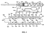
- an exemplary embodiment of this disclosure comprises a solenoid valve 100 comprising a sleeve or housing 110 and a sliding member or spool 120.
- valve 100 is coupled to an actuator assembly 130 and a fluid supply system 140.
- actuator assembly 130 comprises a casing 131, an actuator 132 (having a rod 137 and a piston 135), a first biasing member 133 and a second biasing member 134.
- first and second biasing members 133 and 134 may be compression springs.
- piston 135 of actuator 132 divides a volume of fluid contained within casing 131 into two separate volumes (one on each side of piston 135).
- Rotary actuator embodiments may comprise an actuator that separates the fluid contained within the casing into two volumes, with a first side of the actuator in fluid communication with a first volume, and a second side of the actuator in fluid communication with a second volume.
- the actuator is configured to rotate within the casing rather than slide linearly, and the biasing members may be torsion springs rather than compression springs.
- fluid supply system 140 comprises a reservoir 141.
- fluid supply system may comprise a compressor or pump (not shown) configured to compress a fluid and supply it to reservoir 140.
- fluid supply system 140 may contain air, while in other embodiments, fluid supply system may comprise other fluids, including liquids (for example, hydraulic fluid).
- housing 110 comprises a left end 151, a right end 149, an external wall 129, an internal bore 119 and a series of ports 111-118 and 121-128 extending through external wall 120 to internal bore 119.
- the pair of ports occupying the opposing positions (111 and 121, 112 and 122, ... 118 and 128) are connected via an external flow path (not shown here) and thus can be taken , as the same port.
- exhaust ports 111/121 and 118/128 exhaust to atmosphere, while supply ports 113/123 and 116/126 are coupled to fluid supply system 140 via coupling system 163.
- outlet ports 112/122, 114/124, 115/125, and 117/127 are in fluid communication with actuator assembly 130.
- outlet ports 112/122, 114/124, 115/125, and 117/127 may be in fluid communication with an actuator assembly with a different configuration than that shown in the embodiment of Figures 1-3 .
- Nonlimiting, exemplary embodiments of other such configurations are illustrated in additional figures in this disclosure.
- the term "outlet port" is generally understood to include any port which can be coupled to an actuator to provide fluid communication between the outlet port and the actuator.
- FIG. 1 For purposes of clarity in illustration, in Fig. 1 only ports 121-128 are shown coupled to external components. As shown in Fig. 1 , outlet ports 122 and 124 are coupled to casing 131 on the left side of piston 135 via coupling system 161. Also shown in Fig. 1 , outlet ports 125 and 127 are coupled to casing 131 on the right side of piston 135 via coupling system 162. In exemplary embodiments, coupling systems 161, 162 and 163 may comprise a system of tubing, piping, or any other well-known system used to provide fluid communication between components.
- spool 120 comprises an external surface 148 comprising a series of reliefs or recesses 145-147. Depending upon the position of spool 120 within internal bore 119, external surface 148 or recesses 145-147 will align with one or more ports 111-118 and 121-128. As shown in Fig. 1 , spool 120 is disposed towards left end 151 of housing 110. In this position, recess 145 aligns with ports 111/121 and 112/122 so that they are in fluid communication. In the exemplary embodiment shown in Fig. 1 , recess 146 aligns with port 114/124. Also shown in Fig.
- recess 147 aligns with ports 116/126 and 117/127 so that they are in fluid communication.
- external surface 148 aligns with ports 113/123, 115/125, and 118/128 so that each of these ports is isolated from the other ports.
- external surface 148 is a close tolerance fit within internal bore 119 so that fluid is restricted from flowing from ports 113/123, 115/125, and 118/128 to other ports. As a result, ports 113/123, 115/125, and 118/128 are not in fluid communication with other ports.
- exhaust ports 111/121 and 118/128 exhaust or vent to atmosphere and outlet ports 112/122 and 114/124 are coupled to casing 131 on the left side of piston 135 ( i.e. the left side of casing 131).
- spool 120 When spool 120 is in the position shown in Fig. 1 , the portion of casing 131 on the left side of piston 135 is vented to atmosphere. Therefore, the fluid pressure in the left portion of casing 131 will essentially be atmospheric pressure.
- supply port 116/126 are coupled to fluid supply system 140, and outlet port 117/127 are coupled to the portion of casing 131 to the right of piston 135 (i.e. the right side of casing 131). In the position shown in Fig. 1 , supply port 116/126 is in fluid communication with outlet port 117/127; therefore, the right side of casing 131 will be essentially at or near the pressure in fluid supply system 140.
- the pressure in fluid supply system 140 is greater than atmospheric pressure. Therefore, the pressure in the right side of casing 131 is greater than the pressure in the left side of casing 131. As a result of the differential pressure across piston 135, it will be moved to the left within casing 131.
- biasing members 133 and 134 also exert forces on piston 135.
- the differential fluid pressure across piston 135 compresses biasing member 134 (which exerts a force on piston 135 biasing piston 135 to the right). In the position shown in Figure 1 , biasing member 133 may a force to either the right or left on piston 135.
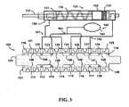
- solenoid valve 100 is shown with spool 120 located in an intermediate position between left end 151 and right end 149. In this position, recess 145 is aligned with outlet port 112/122, but outlet port 112/122 is isolated from other ports. In addition, recess 147 has aligned with outlet port 117/127, but outlet port 117/127 is also isolated from other ports. As shown in the position of Fig. 2 , recess 146 has aligned with outlet ports 114/124 and 115/125 so that these ports are in fluid communication with each other.
- outlet port 114/124 is in fluid communication with the left side of casing 131
- outlet port 115/125 is in fluid communication with the right side of casing 131.
- the left side of casing 131 is in fluid communication with the right side of casing 131.
- external surface 148 has blocked off exhaust ports 111/121 and 118/128 which vent to atmosphere. The right side of casing 131 and the left side of casing 13 are therefore not vented to atmosphere.
- the left side of casing 131 is in fluid communication with the right side of casing 131. Because the right side of casing 131 was initially at a greater pressure than the left side of casing 131, fluid will flow from the right side to the left side of casing 131. More specifically, fluid will flow from the right side of casing 131, through coupling system 162, outlet port 15/125, recess 146, outlet port 114/124, coupling system 161 and to the left side of casing 131. In this manner, fluid from the right side of casing 131 is redirected or recycled to the left side of casing 131.
- biasing member 134 This causes the fluid pressure on the right side of piston 131 to decrease and the fluid pressure on the left side of piston 131 to increase. As the pressure on each side of piston 135 approaches equilibrium, biasing member 134 will exert a force on piston 131 and move it to the right as shown in Fig. 2 . In the configuration shown in Fig. 2 , biasing member 133 is exerting a force on piston 131 towards the left. However, in certain exemplary embodiments, biasing member 134 can exert a counteracting force great enough to overcome the force of biasing member 133.
- biasing member 134 will exert a greater force than biasing member 133 so long as biasing member 134 is compressed a greater amount than biasing member 133 to compensate for the differential force applied to the piston (because the area on the left side of the piston is smaller than the right side by the area of the piston rod, while the pressure is the same), so that the piston is in an equilibrium status.
- spool 120 of solenoid valve 100 is shown in a position proximal to right end 149 of housing 110.
- recess 146 is aligned with port 115/125, but port 115/125 is isolated from other ports.
- recess 147 has aligned with ports 117/127, and 118/128 so that port 117/127 (which is coupled to the right side of casing 131) is vented to atmosphere.
- recess 145 has aligned with ports 112/122 and 113/123 so that port 112/122 (which is coupled to the left side of casing 131) is in fluid communication with fluid supply system 140.
- the left side of casing 131 is at a higher pressure than the right of casing 131 and piston 135 is moved to the right side of casing 131.
- Spool 120 can then be moved from the position shown in Fig. 3 to the position shown in Fig. 2 and the cycle can be repeated. In this manner, piston 135 can be moved within casing 131 based on the position of spool 120 within housing 110. Spool 120 can be moved within housing 110 via an electromagnetic coil (not shown) or by other mechanisms known in the art for positioning solenoid valves. While housing 110 and spool 120 are shown with a cylindrical configuration in the embodiment shown in Figures 1-3 , other embodiments may have different configurations with cross-sections that are not circular. For example, housing 110 and spool 120 may have a cross-section that is shaped like a square or other polygon.
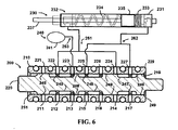
- an alternative embodiment of a solenoid valve system 200 comprises a housing 210, a spool 220, an actuator assembly 230 (having a rod 237 and a piston 235), and a fluid supply system 240.
- Solenoid valve system 200 is generally equivalent to solenoid valve system 100; however, solenoid valve system 200 comprises a different number and configuration of ports than solenoid valve system 100 and the recesses formed in spool 200 are a different configuration than those of spool 100.
- the exemplary embodiment shown in Figure 4 comprises seven ports instead of eight ports.
- Solenoid valve system 200 comprises a single supply port 213/223 coupled to fluid supply system 240 rather than two supply ports as shown in the embodiment of Figs.
- solenoid valve system 200 Other aspects of solenoid valve system 200 are generally equivalent to those of solenoid valve system 100. Therefore, like features and elements in solenoid valve system 200 are identified with similar reference numbers to those used in Figs. 1-3 (with the exception that reference numbers for Figs. 4-6 begin with "2" instead of"1").
- spool 220 is proximal to left end 251 of housing 210.
- recess 245 is aligned with exhaust port 211/221 and port 212/222 which is in fluid communication with the left side of casing 231. Therefore, the left side of casing 231 is generally at atmospheric pressure.
- recess 246 is aligned with supply port 213/223 and port 215/225 which is in fluid communication with the right side of casing 231. Therefore, the right side of casing 231 is generally at the pressure of fluid supply system 240.
- recess 247 has isolated port 214/224 (which is in fluid communication with the left side of casing 231) from the other ports. In the configuration shown in Fig. 4 , piston 235 is forced to the left side of casing 231.
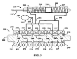
- spool has moved to a position more centrally located between left end 251 and right end 249.
- recess 245 has isolated port 212/222 and recess 246 has isolated port 215/225.
- recess 247 has aligned with port 214/224 (which is in fluid communication with the left side of casing 231) with port 217/227 (which is in fluid communication with the right side of casing 231).
- port 214/224 which is in fluid communication with the left side of casing 231
- port 217/227 which is in fluid communication with the right side of casing 231).
- biasing member 234 biases piston 235 to the position shown in Fig. 5 .
- spool 220 is shown in a position proximal to right end 249 of housing 210.
- recess 245 is aligned with supply port 213/223 and left side port 212/222.
- Recess 246 is aligned with exhaust port 218/228 and right side port 215/225.
- recess 247 is aligned with, and isolates, right side port 217/227.
- the left side of casing 231 is in fluid communication with fluid supply system 240 and the right side of casing 231 is vented to atmosphere. Piston 235 will be moved towards the right end of casing 231.
- Figs. 4-6 can be cycled so that piston 235 is moved from a position near one end of casing 231 towards the other end and back.
- an exemplary embodiment of solenoid valve system 300 comprises a rotary configuration.
- Solenoid valve system 300 can be coupled to an actuator assembly (not shown) similar to actuator assembly 130 or 230 in the previously-described embodiments.
- Solenoid valve system 300 may also be coupled to a fluid supply system similar to fluid supply system 140 or 240 in the previously-described embodiments.
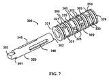
- the embodiment of Figures 7-13 comprises a housing 310 and a rotary member 320 (instead of a spool as shown in the previous embodiments).
- Rotary member 320 rotates within housing 310 to align reliefs or recesses 345-348 on the external surface of rotary member 320 with ports in housing 310.
- Housing 310 comprises a first end 351 and a second end 329 with a series of ports distributed between them.
- housing 310 comprises a series of supply ports 321 proximal to first end 351, and a series of exhaust ports 323 proximal to second end 329.
- Housing 310 further comprises a series of first actuator ports 325 proximal to supply ports 321 and a series of second actuator ports 322 between first actuator ports 325 and exhaust ports 323.
- Housing 310 further comprises a series of sealing members or ridges 305 between the various ports. Ridges 305 allow one set of ports to be isolated from an adjacent set of ports for purposes of preventing fluid communication between the various ports and external systems (such as actuator systems and fluid supply systems). For purposes of clarity, not all ridges 305 are labeled in Figures 7 and 8 .
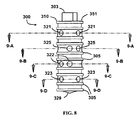
- rotary member 320 comprises a first end 301 and a second end 302.
- First end 301 comprises an engagement member 303 that allows a solenoid actuator (not shown) to rotate rotary member 320.
- rotary member 320 comprises a series of recesses 345-348 along its outer surface.
- Recesses 345 and 347 are approximately 180 degrees apart, and are aligned longitudinally ( i.e ., the recesses are generally the same length and the same distance from first end 301 and second end 302).
- recesses 346 and 348 are also approximately 180 degrees apart and aligned longitudinally.
- FIG. 8 an assembly view of housing 310 and rotary member 320 is shown with rotary member 320 positioned in a specific position within housing 310. Specifically, rotary member 320 is positioned so that first actuator ports 325 are in fluid communication with exhaust ports 323 and second actuator ports 322 are in fluid communication with supply ports 321.
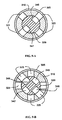
- Figure 9-A a section view taken along line 9-A in Figure 8 illustrates recesses 345 and 347 in alignment with supply ports 321.
- Figure 9-B a section view taken along line 9-B in Figure 8 illustrates recesses 346 and 348 are aligned with first actuator ports 325.
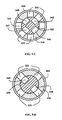
- FIG. 9-C a section view taken along line 9-C in Figure 8 illustrates recesses 345 and 347 in alignment with a pair of second actuator ports 322.
- Figure 9-D a section view taken along line 9-D in Figure 8 illustrates recesses 346 and 348 are aligned with a pair of exhaust ports 323.
- first actuator ports 325 are in fluid communication with exhaust ports 323 (via recesses 346 and 348).
- second actuator ports 322 are in fluid communication with supply ports 321 (via recesses 345 and 347).
- a fluid supply system may be in fluid communication with supply ports 321, while exhaust ports 323 are vented to atmosphere.
- first actuator ports 325 may be in fluid communication with one side of an actuator assembly, while second actuator ports 322 are in fluid communication with an opposing side of the actuator assembly. In such embodiments, placing rotary member 320 in the position shown in Figure 8 can move an actuator to one side of the actuator assembly (similar to the position of actuator assembly 130 shown in Figure 1 ).
- rotary member 320 has been rotated so that it is in a different position from that shown in Figure 8 . Specifically, rotary member 320 has been rotated so that first actuator ports 325 are in fluid communication with second actuator ports 322. In addition, supply ports 321 are not in fluid communication with either first actuator ports 325 or second actuator ports 322. Similarly, exhaust ports 323 are not in fluid communication with either first actuator ports 325 or second actuator ports 322.
- FIG. 11-A a section view taken along line 11-A in Figure 10 illustrates recesses 345 and 347 are not aligned with any of the supply ports 321.
- Figure 11-B a section view taken along line 11-B in Figure 10 illustrates recesses 345 and 347 are in alignment with a pair of first actuator ports 325. Also shown in Figure 11-B , recesses 346 and 348 are aligned with another pair of first actuator ports 325.
- FIG. 11-C a section view taken along line 11-C in Figure 10 illustrates recesses 345 and 347 in alignment with a pair of second actuator ports 322. Also shown in Figure 11-C , recesses 346 and 348 are aligned with another pair of second actuator ports 322. Finally, referring to Figure 11-D , a section view taken along line 11-D in Figure 10 illustrates recesses 346 and 348 are not aligned with any of the exhaust ports 323.
- first actuator ports 325 are in fluid communication with second actuator ports (via recesses 345, 346, 347 and 348).
- supply ports 321 and exhaust ports 323 are not in fluid communication with any ports, and thus are effectively sealed.
- first actuator ports 325 may be in fluid communication with one side of an actuator assembly, while second actuator ports 322 are in fluid communication with an opposing side of the actuator assembly.
- placing rotary member 320 in the position shown in Figure 10 can move an actuator to an intermediate position in the actuator assembly (similar to the position of actuator assembly 130 shown in Figure 2 ).
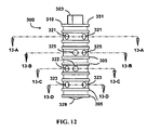
- rotary member 320 has been rotated so that it is in a different position from that shown in Figure 10 . Specifically, rotary member 320 is positioned so that first actuator ports 325 are in fluid communication with supply ports 321 and second actuator ports 322 are in fluid communication with exhaust ports 323.
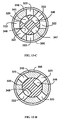
- Figure 13-A a section view taken along line 13-A in Figure 12 illustrates recesses 345 and 347 in alignment with a pair of supply ports 321.
- Figure 13-B a section view taken along line 13-B in Figure 12 illustrates recesses 345 and 347 are aligned with first actuator ports 325.
- a section view taken along line 13-C in Figure 12 illustrates recesses 346 and 348 in alignment with a pair of second actuator ports 322.
- a section view taken along line 13-D in Figure 12 illustrates recesses 346 and 348 are aligned with a pair of exhaust ports 323.
- first actuator ports 325 are in fluid communication with supply ports 321 (via recesses 345 and 347).
- second actuator ports 322 are in fluid communication with exhaust ports 323 (via recesses 346 and 348).
- a fluid supply system may be in fluid communication with supply ports 321, while exhaust ports 323 are vented to atmosphere.
- first actuator ports 325 may be in fluid communication with one side of an actuator assembly, while second actuator ports 322 are in fluid communication with an opposing side of the actuator assembly.
- placing rotary member 320 in the position shown in Figure 12 can move an actuator the side of the actuator assembly that is opposite from actuator position when rotary member 320 is in the position shown in Figure 8 (and similar to the position of actuator assembly 130 shown in Figure 3 ).
- outlet ports may be in fluid communication with both supply ports and exhaust ports in positions intermediate to those shown.
- outlet ports 112/122, 114/124, 115/125, and 117/127 are in fluid communication with exhaust port 111/121 and supply port 116/126.
- the spool can be configured so that the outlet ports are blocked from the exhaust ports and the supply ports during the transition of spool 120.
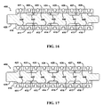
- a solenoid valve 400 comprises a sliding member or spool 420 within a sleeve or housing 410.
- Solenoid valve 400 is generally equivalent to the embodiment shown in Figures 1-3 , with the exception that the geometry of external surface 448 and recesses 445, 446 and 447 are different. Like elements are given like numbers as those shown in Figures 1-3 , with the exception that the numbers begin with "4" instead of "1 ".
- Solenoid valve 400 can also be coupled to an actuator system (not shown for purposes of clarity) similar to that shown in Figures 1-3 . Outlet ports 412/422 and 414/424 are therefore in fluid communication with one another, as are outlet ports 415/425 and 417/427.
- spool 420 is in the leftmost position, and outlet ports 412/422 and 414/424 are in fluid communication with exhaust port 411/421. In addition, outlet ports 415/425 and 417/427 are in fluid communication with supply port 416/426.
- spool 420 has shifted slightly to the right, and all ports are isolated from each other. As spool 420 shifts further to the right, it reaches the central position shown in Figure 17 , and outlet ports 412/422, 414/424, 415/425, and 417/427 are in fluid communication with each other (but isolated from exhaust ports 411/421, 418/428 and supply ports 413/423, 416/426).
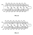
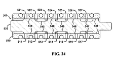
- a modified version of the embodiment shown in Figures 4-6 also comprises a spool with greater travel that is capable of isolating all ports when in intermediate positions.
- Like elements are given like numbers as those shown in Figures 4-6 , with the exception that the numbers begin with "5" instead of "2".
- Solenoid valve 500 is generally equivalent to the embodiment shown in Figures 4-6 , with the exception that the geometry of external surface 548 and recesses 545, 546 and 547 are different.
- outlet ports 512/522 and 516/526 are in fluid communication with exhaust port 511/521.
- outlet ports 514/524 and 517/527 are in fluid communication with supply port 513/523.
- all ports are isolated.
- outlet ports 512/522, 514/524, 516/526, and 517/527 are in fluid communication (and isolated from exhaust ports 511/521, 515/525 and supply ports 513/523.
- all ports are isolated.
- outlet ports 512/522 and 516/526 are in fluid communication with supply port 513/523.
- outlet ports 514/524 and 517/527 are in fluid communication with exhaust port 515/525.
Landscapes
- Engineering & Computer Science (AREA)
- General Engineering & Computer Science (AREA)
- Mechanical Engineering (AREA)
- Physics & Mathematics (AREA)
- Fluid Mechanics (AREA)
- Multiple-Way Valves (AREA)
- Magnetically Actuated Valves (AREA)
- Sliding Valves (AREA)
- Fluid-Pressure Circuits (AREA)
Claims (13)
- Ein System umfassend ein Gehäuse (110), das Gehäuse umfasst:(a) ein erstes Ende (149);(b) ein zweites Ende (151);(c) eine Vielzahl von Öffnungen umfassend Zuflussöffnungen (113, 116, 123, 126), Austrittsöffnungen (111, 118, 121, 128) und Auslassöffilungen (112, 114, 115, 117, 122, 124, 125, 127); und(d) eine Spule (120), die innerhalb des Gehäuses (110) aufgenommen wird, die Spule (120) ist so gestaltet, dass sie sich innerhalb des Gehäuses (110) von einer ersten Position zu einer zweiten Position und zu einer dritten Position bewegt, wobei:sich die zweite Position zwischen der ersten Position und der dritten Position befindet; undeine erste Auslassöffnung (114) in Flüssigkeitskontakt mit einer zweiten Auslassöffnung (115) steht, wenn sich die Spule (120) in der zweiten Position befindet.
- Das System nach Anspruch 1, wobei sich die erste Auslassöffnung (114) neben der zweiten Auslassöffnung (115) befindet.
- Das System nach Anspruch 1, wobei die Spule (120) so gestaltet ist, dass sie innerhalb des Gehäuses (110) quer gleitet oder rotiert.
- Das System nach Anspruch 1, das System umfasst ferner einen Aktor (132), wobei:(a) der Aktor (132) eine erste Seite und eine zweite Seite umfasst;(b) die erste Auslassöffnung (114) in Verbindung mit der ersten Seite des Aktors (132) steht; und(c) die zweite Auslassöffnung (115) in Verbindung mit der zweiten Seite des Aktors (132) steht, oder wobei das System ferner ein erstes Vorspannelement (133) umfasst, das so gestaltet ist, dass es eine erste Kraft auf den Aktor (132) ausübt, und ein zweites Vorspannelement (134), das so gestaltet ist, dass es eine zweite Kraft auf den Aktor (132) ausübt.
- Das System nach Anspruch 1, wobei:(a) wenn sich die Spule (120) in der ersten Position befindet:eine Zuflußöffnung (116, 126) in Flüssigkeitskontakt mit einer Auslassöffnung (117, 127) steht, undeine Austrittsöffnung (111, 121) in Flüssigkeitskontakt mit einer Auslassöffnung (112, 122) steht; und(b) wenn sich die Spule (120) in der dritten Position befindet:eine Zuflussöffnung (113, 123) in Flüssigkeitskontakt mit einer Auslassöffnung (112, 122) steht, undeine Austrittsöffmzng (118, 128) in Flüssigkeitskontakt mit einer Auslassöffnung (117, 127) steht.
- Das System nach Anspruch 1, wobei:(a) sich die Spule (120) proximal zum ersten Ende (151) des Gehäuses (110) befindet, wenn sich die Spule (120) in der ersten Position befindet;(b) sich die Spule (120) proximal zum zweiten Ende (149) des Gehäuses (110) befindet, wenn sich die Spule (120) in der dritten Position befindet.
- Das System nach Anspruch 1, wobei:(a) sich die Vielzahl an Öffnungen über das Gehäuse (110) erstrecken; und(b) die Spule (120) eine Vielzahl von Vertiefungen (145, 146, 147) umfasst, die so gestaltet sind, dass sie an die Vielzahl von Öffnungen angepasst sind.
- Das System nach Anspruch 7, wobei sich die Vertiefungen (145, 146, 147, 345, 347) (a) ringsherum um oder (b) in Längsrichtung entlang der Spule (120, 320) erstrecken.
- Das System nach Anspruch 8, wobei sich die Vertiefungen (145, 146, 147) ringsherum um die Spule (120) erstrecken und wobei die Spule (120) so gestaltet ist, dass sie quer innerhalb des Gehäuses (110) gleitet, um zu gewährleisten, dass ein erster Satz an Öffnungen miteinander in Flüssigkeitskontakt steht, wenn sich die Spule (120) in der ersten Position befindet, und ein zweiter Satz an Öffnungen miteinander in Flüssigkeitskontakt steht, wenn sich die Spule (120) in der zweiten Position befindet, und ein dritter Satz an Öffnungen miteinander in Flüssigkeitskontakt steht, wenn sich die Spule (120) in der dritten Position befindet.
- Das System nach Anspruch 8, wobei sich die Vertiefungen (345, 347) längs entlang der Spule (320) erstrecken und wobei die Spule (320) so gestaltet ist, dass sie innerhalb des Gehäuses (310) rotiert, um zu gewährleisten, dass ein erster Satz an Öffnung miteinander in Flüssigkeitskontakt steht, wenn sich die Spule (320) in der ersten Position befindet, ein zweiter Satz an Öffnungen miteinander in Flüssigkeitskontakt steht, wenn sich die Spule (320) in der zweiten Position befindet und ein dritter Satz an Öffnungen in Flüssigkeitskontakt miteinander steht, wenn sich die Spule (320) in der dritten Position befindet.
- Das System nach Anspruch 4, wobei:(a) der Aktor (132) in einer Hülle (131) angeordnet ist, die ein Flüssigkeitsvolumen umfasst;(b) der Aktor (132) das Flüssigkeitsvolumen in ein erstes Volumen und ein zweites Volumen teilt;(c) die Aktoranordnung (130) in Flüssigkeitskontakt mit einer Magnetventilanordnung (100) steht,(d) die Magnetventilanordnung (100) in einer ersten Position, in einer zweiten Position oder einer dritten Position platziert sein kamn;(e) das erste Volumen nicht in Flüssigkeitskontakt mit dem zweiten Volumen steht, wenn sich die Magnetventilanordnung (100) in der ersten Position oder der dritten Position befindet; und(f) das erste Volumen in Flüssigkeitskontakt mit dem zweiten Volumen steht, wenn sich die Magnetventilanordnung (100) in der zweiten Position befindet.
- Das System nach Anspruch 11, das System umfasst ferner ein Flüssigkeitszuflusssystem (140), wobei:(a) das Flüssigkeitszuflusssystem (140) in Flüssigkeitskontakt mit dem ersten Volumen steht, wenn sich die Magnetventilanordnung (100) in der ersten Position befindet; und(b) das Flüssigkeitszuflusssystem (140) in Flüssigkeitskontakt mit dem zweiten Volumen steht, wenn sich die Magnetventilanordnung (100) in der dritten Position befindet.
- Das System nach Anspruch 11, wobei die Magnetventilanordnung (100) eine Spule (120) umfasst, die so gestaltet ist, dass sie innerhalb des Gehäuses (110) quer gleitet oder rotiert.
Applications Claiming Priority (1)
| Application Number | Priority Date | Filing Date | Title |
|---|---|---|---|
| PCT/US2008/050382 WO2009088504A1 (en) | 2008-01-07 | 2008-01-07 | Solenoid valve assembly |
Publications (2)
| Publication Number | Publication Date |
|---|---|
| EP2240698A1 EP2240698A1 (de) | 2010-10-20 |
| EP2240698B1 true EP2240698B1 (de) | 2011-11-02 |
Family
ID=39790442
Family Applications (1)
| Application Number | Title | Priority Date | Filing Date |
|---|---|---|---|
| EP08780365A Not-in-force EP2240698B1 (de) | 2008-01-07 | 2008-01-07 | Magnetventilanordnung |
Country Status (7)
| Country | Link |
|---|---|
| US (2) | US8635940B2 (de) |
| EP (1) | EP2240698B1 (de) |
| JP (1) | JP5281099B2 (de) |
| AT (1) | ATE531945T1 (de) |
| CA (1) | CA2711398C (de) |
| ES (1) | ES2375781T3 (de) |
| WO (1) | WO2009088504A1 (de) |
Families Citing this family (17)
| Publication number | Priority date | Publication date | Assignee | Title |
|---|---|---|---|---|
| US20080099705A1 (en) | 2006-10-25 | 2008-05-01 | Enfield Technologies, Llc | Retaining element for a mechanical component |
| US8763639B2 (en) | 2007-05-18 | 2014-07-01 | Enfield Technologies, Llc | Electronically controlled valve and systems containing same |
| US9243565B2 (en) * | 2012-09-12 | 2016-01-26 | Hamilton Sundstrand Space Systems International, Inc. | Gas turbine engine fuel system metering valve |
| DE102012222399A1 (de) * | 2012-12-06 | 2014-06-12 | Robert Bosch Gmbh | Stetig verstellbares hydraulisches Einbauventil |
| KR20150130316A (ko) * | 2013-03-14 | 2015-11-23 | 에어로밸브 엘엘씨 | 공압 유체 재순환 지연 기능을 가진 공압식 방향 제어 밸브를 위한 안전 기구 |
| GB201320192D0 (en) * | 2013-11-15 | 2014-01-01 | Blagdon Actuation Res Ltd | Servo Valves |
| DE102015210274A1 (de) * | 2014-06-03 | 2015-12-03 | Voith Patent Gmbh | Mehrwegeventil, insbesondere ein 6/2-Wegeventil und Mehrwegeventilanordnung |
| JP6461869B2 (ja) * | 2016-03-30 | 2019-01-30 | Ckd株式会社 | 流路切替弁、及びその製造方法 |
| US10550863B1 (en) | 2016-05-19 | 2020-02-04 | Steven H. Marquardt | Direct link circuit |
| US11015624B2 (en) | 2016-05-19 | 2021-05-25 | Steven H. Marquardt | Methods and devices for conserving energy in fluid power production |
| US10914322B1 (en) * | 2016-05-19 | 2021-02-09 | Steven H. Marquardt | Energy saving accumulator circuit |
| CN107816561B (zh) * | 2016-09-12 | 2020-04-03 | 杭州三花研究院有限公司 | 一种换向装置 |
| US10711903B2 (en) * | 2017-06-08 | 2020-07-14 | Hamilton Sundstrand Corporation | Transfer valves |
| JP6955436B2 (ja) | 2017-12-25 | 2021-10-27 | Ckd株式会社 | 電磁アクチュエータ |
| DE102018003000A1 (de) | 2018-04-12 | 2019-10-17 | Festo Ag & Co. Kg | Ausgleichsventil, Ventilsystem und Pneumatiksystem |
| DE102021109742B4 (de) | 2021-04-19 | 2023-10-26 | Audi Aktiengesellschaft | Zentralventileinrichtung mit Anschlussraster und drehbarem Verstellelement für ein Kühlsystem eines Kraftfahrzeugs und Elektrofahrzeug mit einem solchen Kühlsystem |
| CN115218032A (zh) * | 2022-08-30 | 2022-10-21 | 靖江佳佳精密机械科技有限公司 | 一种半导体真空阀门和电磁阀连通结构及半导体真空阀门 |
Family Cites Families (26)
| Publication number | Priority date | Publication date | Assignee | Title |
|---|---|---|---|---|
| US2166940A (en) * | 1930-03-12 | 1939-07-25 | Conrad M Conradson | Hydraulic power system |
| US2637341A (en) * | 1949-07-27 | 1953-05-05 | Westinghouse Air Brake Co | Fluid pressure control valve device |
| FR1465422A (fr) * | 1965-08-06 | 1967-01-13 | Dispositif de direction hydraulique notamment assisté | |
| JPS4828829Y1 (de) * | 1969-02-26 | 1973-09-01 | ||
| JPS4828829A (de) | 1971-08-17 | 1973-04-17 | ||
| US3916952A (en) * | 1972-04-12 | 1975-11-04 | Richard S Pauliukonis | Energy conserving tandem directional valve |
| US3736958A (en) * | 1972-04-13 | 1973-06-05 | Lockheed Aircraft Corp | Four-way solenoid selector valve |
| JPS5798384U (de) * | 1980-12-10 | 1982-06-17 | ||
| JPS5798384A (en) | 1980-12-11 | 1982-06-18 | Oki Electric Ind Co Ltd | Printer |
| JPS5888276A (ja) | 1981-11-17 | 1983-05-26 | Komatsu Ltd | 電磁油圧切換弁 |
| JPH0518536Y2 (de) * | 1986-09-03 | 1993-05-17 | ||
| JPS6345273A (ja) | 1987-02-06 | 1988-02-26 | Nisshin Flour Milling Co Ltd | α−トコフエロ−ル誘導体 |
| JP2517077B2 (ja) | 1988-09-20 | 1996-07-24 | 松下冷機株式会社 | 蓄冷型保冷庫 |
| JPH0717636Y2 (ja) * | 1988-12-22 | 1995-04-26 | 株式会社ユニシアジェックス | 圧力制御装置 |
| JPH03278206A (ja) * | 1990-03-28 | 1991-12-09 | Mitsubishi Electric Corp | 電磁流量制御装置 |
| US5163353A (en) * | 1991-12-12 | 1992-11-17 | Ross Operating Valve Company | Energy saving and monitoring pneumatic control valve system |
| DE4227563C2 (de) | 1992-08-20 | 2000-04-13 | Mannesmann Rexroth Ag | Geregelter hydraulischer Vorschubantrieb |
| DE19542200C2 (de) * | 1995-11-13 | 2000-04-27 | Daimler Chrysler Ag | Servoventil |
| JP4527410B2 (ja) * | 1999-05-13 | 2010-08-18 | 株式会社アマダ | 制御バルブ |
| JP4342070B2 (ja) * | 2000-02-21 | 2009-10-14 | 株式会社アマダ | 方向制御弁 |
| US6755714B1 (en) | 2000-08-30 | 2004-06-29 | Jerry R. Huddleston | Remotely operable game caller |
| JP2002156053A (ja) * | 2000-11-16 | 2002-05-31 | Amada Eng Center Co Ltd | 方向切換弁 |
| US6755214B2 (en) * | 2001-08-03 | 2004-06-29 | Ross Operating Value Company | Solenoid valve for reduced energy consumption |
| DE10247967B3 (de) | 2002-10-15 | 2004-02-05 | Festo Ag & Co. | Mehrwegeventil mit Fluidsparmaßnahmen |
| CA2507501C (en) | 2002-11-27 | 2011-10-04 | Incyte Corporation | 3-aminopyrrolidine derivatives as modulators of chemokine receptors |
| JP4614178B1 (ja) | 2010-02-18 | 2011-01-19 | 誠 小野寺 | 電気掃除機用ノズル |
-
2008
- 2008-01-07 CA CA2711398A patent/CA2711398C/en not_active Expired - Fee Related
- 2008-01-07 JP JP2010541447A patent/JP5281099B2/ja not_active Expired - Fee Related
- 2008-01-07 US US12/811,802 patent/US8635940B2/en not_active Expired - Fee Related
- 2008-01-07 AT AT08780365T patent/ATE531945T1/de active
- 2008-01-07 ES ES08780365T patent/ES2375781T3/es active Active
- 2008-01-07 EP EP08780365A patent/EP2240698B1/de not_active Not-in-force
- 2008-01-07 WO PCT/US2008/050382 patent/WO2009088504A1/en not_active Ceased
-
2013
- 2013-12-20 US US14/135,915 patent/US9605768B2/en not_active Expired - Fee Related
Also Published As
| Publication number | Publication date |
|---|---|
| US8635940B2 (en) | 2014-01-28 |
| ATE531945T1 (de) | 2011-11-15 |
| WO2009088504A1 (en) | 2009-07-16 |
| US20110005625A1 (en) | 2011-01-13 |
| CA2711398A1 (en) | 2009-07-16 |
| CA2711398C (en) | 2015-07-14 |
| EP2240698A1 (de) | 2010-10-20 |
| JP2011508862A (ja) | 2011-03-17 |
| US20140158922A1 (en) | 2014-06-12 |
| ES2375781T3 (es) | 2012-03-06 |
| JP5281099B2 (ja) | 2013-09-04 |
| US9605768B2 (en) | 2017-03-28 |
Similar Documents
| Publication | Publication Date | Title |
|---|---|---|
| EP2240698B1 (de) | Magnetventilanordnung | |
| US20120260993A1 (en) | Poppet valve assembly for controlling a pneumatic actuator | |
| EP3129660B1 (de) | Servoventil | |
| CN104895859B (zh) | 具有负载保持功能的阀组件 | |
| EP3066370B1 (de) | Vorrichtung zur vorspannung von spulenventilen mittels versorgungsdruck | |
| GB2428460A (en) | Solenoid system | |
| EP1803980B1 (de) | Ventil mit Hohlkolben | |
| US6786236B2 (en) | Electrohydraulic servo valve | |
| EP2635829B1 (de) | Vorspannungsvorrichtung zur anwendung mit fluidventilaktoren | |
| US8408237B2 (en) | Modular spool valve | |
| EP0950816B1 (de) | Kugel-Sitzventil mit pneumatischer Steuerung | |
| US6408877B2 (en) | Directional control valve | |
| EP3409988B1 (de) | Pneumatisches servoventil mit einstellbaren dosierelementen | |
| EP4004369B1 (de) | Manuelle hydraulische übersteuerungspumpen zur verwendung mit aktuatoren | |
| US9709180B2 (en) | Directional poppet valve | |
| CN108843638B (zh) | 一种内嵌式双阀芯导控机构以及流体控制阀 | |
| WO2015088546A1 (en) | Ball valve assembly | |
| RU2333401C1 (ru) | Двухкаскадный гидрораспределитель с регулированием времени переключения золотника второго каскада | |
| EP3167215B1 (de) | Implementierungssystem für verschiebbare magnetventile | |
| JP2000097366A (ja) | 方向制御弁 | |
| CN121594215A (zh) | 多路控制阀 | |
| WO2006006873A1 (en) | Directly operated control valve in a valve device | |
| KR940000941A (ko) | 연속위치 제어장치 |
Legal Events
| Date | Code | Title | Description |
|---|---|---|---|
| PUAI | Public reference made under article 153(3) epc to a published international application that has entered the european phase |
Free format text: ORIGINAL CODE: 0009012 |
|
| 17P | Request for examination filed |
Effective date: 20100730 |
|
| AK | Designated contracting states |
Kind code of ref document: A1 Designated state(s): AT BE BG CH CY CZ DE DK EE ES FI FR GB GR HR HU IE IS IT LI LT LU LV MC MT NL NO PL PT RO SE SI SK TR |
|
| AX | Request for extension of the european patent |
Extension state: AL BA MK RS |
|
| RIN1 | Information on inventor provided before grant (corrected) |
Inventor name: GOLDFARB, MICHAEL Inventor name: SHEN, XIANGRONG |
|
| DAX | Request for extension of the european patent (deleted) | ||
| GRAP | Despatch of communication of intention to grant a patent |
Free format text: ORIGINAL CODE: EPIDOSNIGR1 |
|
| GRAS | Grant fee paid |
Free format text: ORIGINAL CODE: EPIDOSNIGR3 |
|
| GRAA | (expected) grant |
Free format text: ORIGINAL CODE: 0009210 |
|
| AK | Designated contracting states |
Kind code of ref document: B1 Designated state(s): AT BE BG CH CY CZ DE DK EE ES FI FR GB GR HR HU IE IS IT LI LT LU LV MC MT NL NO PL PT RO SE SI SK TR |
|
| REG | Reference to a national code |
Ref country code: GB Ref legal event code: FG4D |
|
| REG | Reference to a national code |
Ref country code: CH Ref legal event code: EP |
|
| REG | Reference to a national code |
Ref country code: IE Ref legal event code: FG4D |
|
| REG | Reference to a national code |
Ref country code: DE Ref legal event code: R096 Ref document number: 602008011118 Country of ref document: DE Effective date: 20120119 |
|
| REG | Reference to a national code |
Ref country code: NL Ref legal event code: VDEP Effective date: 20111102 |
|
| REG | Reference to a national code |
Ref country code: ES Ref legal event code: FG2A Ref document number: 2375781 Country of ref document: ES Kind code of ref document: T3 Effective date: 20120306 |
|
| LTIE | Lt: invalidation of european patent or patent extension |
Effective date: 20111102 |
|
| PG25 | Lapsed in a contracting state [announced via postgrant information from national office to epo] |
Ref country code: NO Free format text: LAPSE BECAUSE OF FAILURE TO SUBMIT A TRANSLATION OF THE DESCRIPTION OR TO PAY THE FEE WITHIN THE PRESCRIBED TIME-LIMIT Effective date: 20120202 Ref country code: LT Free format text: LAPSE BECAUSE OF FAILURE TO SUBMIT A TRANSLATION OF THE DESCRIPTION OR TO PAY THE FEE WITHIN THE PRESCRIBED TIME-LIMIT Effective date: 20111102 Ref country code: IS Free format text: LAPSE BECAUSE OF FAILURE TO SUBMIT A TRANSLATION OF THE DESCRIPTION OR TO PAY THE FEE WITHIN THE PRESCRIBED TIME-LIMIT Effective date: 20120302 |
|
| PG25 | Lapsed in a contracting state [announced via postgrant information from national office to epo] |
Ref country code: GR Free format text: LAPSE BECAUSE OF FAILURE TO SUBMIT A TRANSLATION OF THE DESCRIPTION OR TO PAY THE FEE WITHIN THE PRESCRIBED TIME-LIMIT Effective date: 20120203 Ref country code: BE Free format text: LAPSE BECAUSE OF FAILURE TO SUBMIT A TRANSLATION OF THE DESCRIPTION OR TO PAY THE FEE WITHIN THE PRESCRIBED TIME-LIMIT Effective date: 20111102 Ref country code: PL Free format text: LAPSE BECAUSE OF FAILURE TO SUBMIT A TRANSLATION OF THE DESCRIPTION OR TO PAY THE FEE WITHIN THE PRESCRIBED TIME-LIMIT Effective date: 20111102 Ref country code: NL Free format text: LAPSE BECAUSE OF FAILURE TO SUBMIT A TRANSLATION OF THE DESCRIPTION OR TO PAY THE FEE WITHIN THE PRESCRIBED TIME-LIMIT Effective date: 20111102 Ref country code: LV Free format text: LAPSE BECAUSE OF FAILURE TO SUBMIT A TRANSLATION OF THE DESCRIPTION OR TO PAY THE FEE WITHIN THE PRESCRIBED TIME-LIMIT Effective date: 20111102 Ref country code: PT Free format text: LAPSE BECAUSE OF FAILURE TO SUBMIT A TRANSLATION OF THE DESCRIPTION OR TO PAY THE FEE WITHIN THE PRESCRIBED TIME-LIMIT Effective date: 20120302 Ref country code: HR Free format text: LAPSE BECAUSE OF FAILURE TO SUBMIT A TRANSLATION OF THE DESCRIPTION OR TO PAY THE FEE WITHIN THE PRESCRIBED TIME-LIMIT Effective date: 20111102 Ref country code: SE Free format text: LAPSE BECAUSE OF FAILURE TO SUBMIT A TRANSLATION OF THE DESCRIPTION OR TO PAY THE FEE WITHIN THE PRESCRIBED TIME-LIMIT Effective date: 20111102 Ref country code: SI Free format text: LAPSE BECAUSE OF FAILURE TO SUBMIT A TRANSLATION OF THE DESCRIPTION OR TO PAY THE FEE WITHIN THE PRESCRIBED TIME-LIMIT Effective date: 20111102 |
|
| PG25 | Lapsed in a contracting state [announced via postgrant information from national office to epo] |
Ref country code: CY Free format text: LAPSE BECAUSE OF FAILURE TO SUBMIT A TRANSLATION OF THE DESCRIPTION OR TO PAY THE FEE WITHIN THE PRESCRIBED TIME-LIMIT Effective date: 20111102 |
|
| PG25 | Lapsed in a contracting state [announced via postgrant information from national office to epo] |
Ref country code: CZ Free format text: LAPSE BECAUSE OF FAILURE TO SUBMIT A TRANSLATION OF THE DESCRIPTION OR TO PAY THE FEE WITHIN THE PRESCRIBED TIME-LIMIT Effective date: 20111102 Ref country code: SK Free format text: LAPSE BECAUSE OF FAILURE TO SUBMIT A TRANSLATION OF THE DESCRIPTION OR TO PAY THE FEE WITHIN THE PRESCRIBED TIME-LIMIT Effective date: 20111102 Ref country code: DK Free format text: LAPSE BECAUSE OF FAILURE TO SUBMIT A TRANSLATION OF THE DESCRIPTION OR TO PAY THE FEE WITHIN THE PRESCRIBED TIME-LIMIT Effective date: 20111102 Ref country code: EE Free format text: LAPSE BECAUSE OF FAILURE TO SUBMIT A TRANSLATION OF THE DESCRIPTION OR TO PAY THE FEE WITHIN THE PRESCRIBED TIME-LIMIT Effective date: 20111102 Ref country code: BG Free format text: LAPSE BECAUSE OF FAILURE TO SUBMIT A TRANSLATION OF THE DESCRIPTION OR TO PAY THE FEE WITHIN THE PRESCRIBED TIME-LIMIT Effective date: 20120202 |
|
| PG25 | Lapsed in a contracting state [announced via postgrant information from national office to epo] |
Ref country code: MC Free format text: LAPSE BECAUSE OF NON-PAYMENT OF DUE FEES Effective date: 20120131 Ref country code: RO Free format text: LAPSE BECAUSE OF FAILURE TO SUBMIT A TRANSLATION OF THE DESCRIPTION OR TO PAY THE FEE WITHIN THE PRESCRIBED TIME-LIMIT Effective date: 20111102 |
|
| REG | Reference to a national code |
Ref country code: CH Ref legal event code: PL |
|
| PLBE | No opposition filed within time limit |
Free format text: ORIGINAL CODE: 0009261 |
|
| STAA | Information on the status of an ep patent application or granted ep patent |
Free format text: STATUS: NO OPPOSITION FILED WITHIN TIME LIMIT |
|
| REG | Reference to a national code |
Ref country code: AT Ref legal event code: MK05 Ref document number: 531945 Country of ref document: AT Kind code of ref document: T Effective date: 20111102 |
|
| 26N | No opposition filed |
Effective date: 20120803 |
|
| REG | Reference to a national code |
Ref country code: IE Ref legal event code: MM4A |
|
| PG25 | Lapsed in a contracting state [announced via postgrant information from national office to epo] |
Ref country code: LI Free format text: LAPSE BECAUSE OF NON-PAYMENT OF DUE FEES Effective date: 20120131 Ref country code: CH Free format text: LAPSE BECAUSE OF NON-PAYMENT OF DUE FEES Effective date: 20120131 |
|
| REG | Reference to a national code |
Ref country code: DE Ref legal event code: R097 Ref document number: 602008011118 Country of ref document: DE Effective date: 20120803 |
|
| PG25 | Lapsed in a contracting state [announced via postgrant information from national office to epo] |
Ref country code: IE Free format text: LAPSE BECAUSE OF NON-PAYMENT OF DUE FEES Effective date: 20120107 Ref country code: AT Free format text: LAPSE BECAUSE OF FAILURE TO SUBMIT A TRANSLATION OF THE DESCRIPTION OR TO PAY THE FEE WITHIN THE PRESCRIBED TIME-LIMIT Effective date: 20111102 |
|
| PG25 | Lapsed in a contracting state [announced via postgrant information from national office to epo] |
Ref country code: FI Free format text: LAPSE BECAUSE OF FAILURE TO SUBMIT A TRANSLATION OF THE DESCRIPTION OR TO PAY THE FEE WITHIN THE PRESCRIBED TIME-LIMIT Effective date: 20111102 |
|
| PG25 | Lapsed in a contracting state [announced via postgrant information from national office to epo] |
Ref country code: MT Free format text: LAPSE BECAUSE OF FAILURE TO SUBMIT A TRANSLATION OF THE DESCRIPTION OR TO PAY THE FEE WITHIN THE PRESCRIBED TIME-LIMIT Effective date: 20111102 |
|
| PG25 | Lapsed in a contracting state [announced via postgrant information from national office to epo] |
Ref country code: TR Free format text: LAPSE BECAUSE OF FAILURE TO SUBMIT A TRANSLATION OF THE DESCRIPTION OR TO PAY THE FEE WITHIN THE PRESCRIBED TIME-LIMIT Effective date: 20111102 |
|
| PG25 | Lapsed in a contracting state [announced via postgrant information from national office to epo] |
Ref country code: LU Free format text: LAPSE BECAUSE OF NON-PAYMENT OF DUE FEES Effective date: 20120107 |
|
| PG25 | Lapsed in a contracting state [announced via postgrant information from national office to epo] |
Ref country code: HU Free format text: LAPSE BECAUSE OF FAILURE TO SUBMIT A TRANSLATION OF THE DESCRIPTION OR TO PAY THE FEE WITHIN THE PRESCRIBED TIME-LIMIT Effective date: 20080107 |
|
| REG | Reference to a national code |
Ref country code: FR Ref legal event code: PLFP Year of fee payment: 9 |
|
| REG | Reference to a national code |
Ref country code: FR Ref legal event code: PLFP Year of fee payment: 10 |
|
| REG | Reference to a national code |
Ref country code: FR Ref legal event code: PLFP Year of fee payment: 11 |
|
| PGFP | Annual fee paid to national office [announced via postgrant information from national office to epo] |
Ref country code: GB Payment date: 20190128 Year of fee payment: 12 Ref country code: DE Payment date: 20190129 Year of fee payment: 12 Ref country code: ES Payment date: 20190201 Year of fee payment: 12 Ref country code: FR Payment date: 20190125 Year of fee payment: 12 Ref country code: IT Payment date: 20190123 Year of fee payment: 12 |
|
| REG | Reference to a national code |
Ref country code: DE Ref legal event code: R119 Ref document number: 602008011118 Country of ref document: DE |
|
| GBPC | Gb: european patent ceased through non-payment of renewal fee |
Effective date: 20200107 |
|
| PG25 | Lapsed in a contracting state [announced via postgrant information from national office to epo] |
Ref country code: DE Free format text: LAPSE BECAUSE OF NON-PAYMENT OF DUE FEES Effective date: 20200801 Ref country code: FR Free format text: LAPSE BECAUSE OF NON-PAYMENT OF DUE FEES Effective date: 20200131 Ref country code: GB Free format text: LAPSE BECAUSE OF NON-PAYMENT OF DUE FEES Effective date: 20200107 |
|
| PG25 | Lapsed in a contracting state [announced via postgrant information from national office to epo] |
Ref country code: IT Free format text: LAPSE BECAUSE OF NON-PAYMENT OF DUE FEES Effective date: 20200107 |
|
| REG | Reference to a national code |
Ref country code: ES Ref legal event code: FD2A Effective date: 20210602 |
|
| PG25 | Lapsed in a contracting state [announced via postgrant information from national office to epo] |
Ref country code: ES Free format text: LAPSE BECAUSE OF NON-PAYMENT OF DUE FEES Effective date: 20200108 |