EP2240651B1 - Profilleistenvorrichtung - Google Patents
Profilleistenvorrichtung Download PDFInfo
- Publication number
- EP2240651B1 EP2240651B1 EP09709217A EP09709217A EP2240651B1 EP 2240651 B1 EP2240651 B1 EP 2240651B1 EP 09709217 A EP09709217 A EP 09709217A EP 09709217 A EP09709217 A EP 09709217A EP 2240651 B1 EP2240651 B1 EP 2240651B1
- Authority
- EP
- European Patent Office
- Prior art keywords
- profiled strip
- receptacle
- head
- leg
- profile
- Prior art date
- Legal status (The legal status is an assumption and is not a legal conclusion. Google has not performed a legal analysis and makes no representation as to the accuracy of the status listed.)
- Active
Links
Images




Classifications
-
- E—FIXED CONSTRUCTIONS
- E04—BUILDING
- E04F—FINISHING WORK ON BUILDINGS, e.g. STAIRS, FLOORS
- E04F19/00—Other details of constructional parts for finishing work on buildings
- E04F19/08—Built-in cupboards; Masks of niches; Covers of holes enabling access to installations
Definitions
- the invention relates to a profiled strip device, with a first profiled strip and a second profiled strip, both of which are formed as continuous or juxtaposed metal profiled strips of, for example, aluminum or steel, wherein the second profiled strip with at least one mounting head in at least one receptacle on the first profiled strip form-fitting and at the same time releasably engages, wherein furthermore the first profile strip is equipped with a plurality of arranged along a leg receptacles for positionally variable fixing of the second profile strip, wherein further the fastening head as the longitudinal extent of the associated second profile strip following Befest Trentskopfprofiltechnik and recording is designed as extending in the longitudinal extent of the associated first profile strip receiving groove , and wherein on the receptacle an insertion opening for the fastening head is provided.
- Moldings are generally used in the construction sector for enclosing or delimiting, for example, floors as dividing strips, for windows for stabilization, for the production of frames, etc.
- profile strips are characterized by their strip character and additional profiling. It is very particularly preferred to produce frames with the aid of such profile strip devices, ie frames for covering wall, floor or ceiling openings.
- An example of a profiled strip device is in DE 20 2008 001 831 U1 described. Similar goes the DE 20 2007 001 538 U1 in front.
- the profiled strip device serves, for example, an inspection cover and / or a revision frame of a revision device manufacture.
- a planking using the second profile strip or a fastening device is fixed. This usually happens at the factory.
- DE 20 2007 001 538 U1 It is striking that depending on the thickness of the planking on differently shaped fastening devices must be used as quasi second profile strip. This also increases the assembly-technical effort and is in need of improvement from the handling, especially since the fastening device must be inserted as it were in a revision frame and / or inspection cover.
- a revision device which has a fastening device with the aid of a planking or generally a panel is set.
- the fastening device is adjustably connected to the associated revision frame.
- the fastening device is composed of interlocking hook elements.
- the fastening device can be connected depth adjustable to a revision frame.
- the invention is based on the technical problem of further developing a profile strip device of the embodiment described at the outset such that the attachment of a planking to, for example, the second profile strip is simple and easy, and the assembly is simplified in summary.
- a generic profile rail device in the invention is characterized in that the fastening head is designed so resilient that the fastening head can be elastically compressed yielding when it is inserted through the insertion into the receptacle and after passing the insertion in the receptacle can expand back to its original dimension resiliently to be automatically fixed by this process in the recording and this, the mounting head of the second profile strip and the mounting head enclosing receiving the first profile strip have a cross-section, which is circular in shape, wherein the cross section the receptacle has at least one recess which protrudes with respect to the cross-sectional area of the receptacle and / or the cross-section of the fastening head has at least one bulge, which faces the cross protruding surface of the mounting head.
- the mounting head can change its shape elastically resilient.
- the mounting head is composed according to an advantageous embodiment of two or more spaced apart head legs.
- the two head legs may be arranged with a central gap to each other and in each case taken together form the cross section of the mounting head.
- a special mounting head which is elastically resilient or can change its shape and this
- this elastic suspension is realized in the context of a spatially open design of the mounting head, namely by the two or more spaced apart head legs and / or in that the fastening head is made hollow.
- the head legs can therefore change their distance and / or angle to each other elastically resilient, which is why the described by the two head legs cross-section of the mounting head changes overall elastic yielding its shape.
- the mounting head dips into the receptacle on the first profile strip on the second profile strip, wherein the receptacle only at least partially surrounds the fastening head when it is elastically yielding to a certain extent and / or its former Shape changed. Due to the inherent spring forces of the mounting head this endeavors to return to its original shape. As a result, the mounting head is jammed or wedged in the receptacle and ensures that the second profile strip is fixed to the first profile strip, in a certain position of the two strips to each other.
- the union between the first and the second profile strip may be done in the simplest case so that the mounting head is clipped into the receptacle. Due to the elastic spring properties of the mounting head, it is of course also possible to remove it again from the receptacle and consequently to dissolve the established connection between the first and second profile strip again and / or to change the position of the strips to each other. That is, between the first and the second profile strip, there is a temporary connection, wherein the fastening head in the up is received substantially form-fitting and releasable.
- the attachment head is regularly, but not necessarily elastically resilient.
- the two heads defining the fastening head are connected to a common base.
- this common base is the second profile strip itself or a leg of the second profile strip, which can not be limited to a planking, a plate, or other facilities can be attached.
- the two head legs of the mounting head are usually designed differently under. In fact, it is in the one head leg to a hook leg, while the other head leg is designed as a locking leg. With the hook leg, the second profile strip is able to engage behind, for example, a projection in or on the recording of the first profile strip in its installed position. Of course, this rear grab alternatively or additionally done by the locking legs. If both head legs engage behind an associated projection in the receptacle of the first profile strip, the receptacle is equipped with respective projections which frame an insertion opening of the receptacle. Through this insertion opening of the mounting head is inserted into the receptacle and thereby elastically yielding compressed.
- the fastening head After passing through the insertion opening, the fastening head can then resiliently expand in the receptacle back to its original dimension and is automatically fixed in the receptacle by this process. As a result, the second profile strip learns the desired definition of the first profile strip.
- the hook leg and the latching leg are arranged end-to-end on the base and at an angle to each other and to the base.
- the locking leg and the hook legs are connected at about 90 ° to the base.
- the base end may have a V-bar, which in turn with its respective V-leg on the one hand, the locking leg and on the other hand, the hook leg wearing.
- the respective V-leg is connected with his foot to the base, while the head carries either the locking leg or the hook leg.
- the mounting head is equipped with at least one guide arc.
- This guide sheet slides in taking the installation position of the second profile strip relative to the first profile strip generally along the edge of the receptacle or a projection realized at this point along.
- the fastening head is compressed from the cross-section or changed in its design so that it can pass through the insertion opening of the receptacle and dive into it.
- the guide bow is no longer at the edge of the receptacle or a local projection, so that any forces compressing the mounting head omitted and this spring resumes its original shape and tilted in the recording or in this is jammed.
- the receptacle is defined by at least two receiving legs, against which the fastening head or the latching leg and the hook leg in the installed position. Because the mounting head is composed of the two head legs, it is able to perform elastic changes in certain areas cross-sectional changes. All the more so, as the two profile strips are usually designed as a continuous or juxtaposed metal profile strips made of, for example, aluminum or steel. Accordingly, both profile strips and in particular the fastening head of the second profile strip have the required formula elasticity. As a result, not only the mounting head can be set substantially form-fitting and releasable in the recording, but also any manufacturing tolerances of the mounting head respectively the recording are recorded and balanced.
- the attachment head is regularly a fastening head profiling, which follows the longitudinal extent of the associated profile strip.
- the receptacle is designed as extending in the longitudinal extent of the associated profile strip receiving groove.
- the first profile strip is equipped with a plurality of receptacles arranged along its one leg.
- the second profile strip which can be clamped with the first profile strip, can be fixed in different (height) positions on the said leg and thus on the first profile strip.
- a planking, a panel, etc. are fixed to the second profile strip, with depending on the selected recording variable (height) position in comparison to the first profile strip.
- the invention also provides an inspection device which is equipped with a revision frame and an inspection cover which can be inserted into the inspection frame. Both the inspection frame and the inspection cover can be equipped with a frame profile for receiving a planking.
- This frame profile of either the inspection frame or the inspection cover or both can now be prepared according to the invention of a profiled strip device, as described in the introduction.
- the first profile strip is designed as a frame profile of the inspection frame and / or the inspection cover and the second profile strip as a fastening device for fixing the mentioned planking.
- the second profile strip can be introduced with its mounting head in an installed position in the receptacle and can then be pivoted into a working position. During this pivoting into the working position, the second profile strip is simultaneously fixed relative to the first profile strip. This is done through the interaction of mounting head and recording.
- the second profiled strip thus experiences, at least in its working position, a fixation with respect to the first profiled strip, to be precise automatically when changing from the installation position to the working position. Because the second profile strip in this working position is arranged regularly perpendicular to the first profile strip or a leg carrying the receptacle and experiences the described fixation in the working position, a planking or a cladding or the like on the second profile strip can be determined easily. This also succeeds retrospectively, for example, in the event that a revision cover has been produced with the help of the profile strip device according to the invention and the planking should be installed only to complete all installation work.
- the planking of the inspection cover in the example described is not damaged during the entire installation work on a regular ceiling or a raised floor or on or behind a wall paneling.
- such installation work requires that the inspection cover is removed from the inspection frame.
- the result is that the inspection cover is often parked on the construction site "somewhere" and can be damaged accordingly or worse, even completely lost.
- planking is installed in the inspection cover only when the described work is completed.
- the invention additionally allows an increased flexibility over the prior art, for example, only shortly before installation, the color of the planking must be fixed, and any size or design changes can still be made shortly before completion of the work if necessary. The same applies of course in the event that the planking on the revision framework - as described - is determined.
- the automatic fixing of the fastening head in the receptacle takes place in such a way that the fastening head is clamped during pivoting from the installation position into the working position in the receptacle of the first profiled strip.
- the mounting head the second profile strip and surrounding him receiving the first profile strip in cross section and in combination either alternately round / eccentric or both eccentric.
- the attachment head may have a circular cross-sectional shape and is held in an eccentric receptacle. It is equally conceivable that the mounting head has an eccentric cross section and engages in a round recording.
- both the mounting head and the receptacle are each formed eccentrically in cross section.
- the attachment head is regularly composed of two head thighs with a central gap. The two head legs together form the cross section of the mounting head, which is designed circular or eccentric.
- this has at least one bulge, which protrudes with respect to a (imaginary) cross-sectional circular area.
- two bulges are realized on the mounting head, which are preferably substantially diametrically opposed, as compared to a center. The center coincides with the center of the (imaginary) cross-sectional circular area.
- this invention possesses at least one recess, which protrudes with respect to the cross-sectional area of the receptacle.
- the receptacle is equipped with two receiving legs, which enclose a circular to eccentric opening between them.
- the two receiving legs define an insertion gap for the mounting head.
- the insertion gap sweeps over a specific arc angle range. This may be located between 40 ° and 120 °.
- the arc angle range is 60 ° to 100 ° and more preferably a range between 70 ° and 90 °.
- the mounting head is also composed of two head legs
- Both the recording and the mounting head are able to perform elastic changes in cross-sectional changes in certain areas. All the more so, as the two profile strips are usually designed as a metal profile strips, for example, aluminum or steel. Due to this elasticity of both the mounting head and the recording, it is easy to jam the mounting head when changing from the mounting position to the working position in the recording and the head can be easily released when pivoting back from the working position to the mounting position. In addition, this formula ensures elasticity of the mounting head as the recording that any manufacturing tolerances of the mounting head respectively the recording can be added and compensated.
- the attachment head is regularly a fastening head profiling, which follows the longitudinal extent of the associated profile strip.
- the receptacle is designed as extending in the longitudinal extent of the associated profile strip receiving groove. This makes it necessary that the second profile strip is inserted with its mounting head or its Befest Trentskopfprofiltechnik in the receptacle or receiving groove of the first profile strip or must be inserted. That is, the installation position ultimately represents an insertion position or insertion position. Accordingly, the working position corresponds to a clamping position.
- Both the insertion position and the clamping position correspond to a particular angle that the second profile strip occupies or occupy with respect to the first profile strip.
- the cultivation of the second profile strip thus imperatively requires compliance with the insertion angle associated with the insertion angle.
- a certain clamping angle which specifies the working position.
- the already mentioned insertion gap of the receptacle is opened asymmetrically in comparison to an axis of symmetry of the recording.
- the invention takes into account the fact that the second profile strip from its installation position or insertion position to the working position or clamping position is pivoted almost at right angles.
- the two profile strips are equipped with the aforementioned pivot angles both the insertion angle or clamping angle limiting attacks.
- the first profile strip is equipped with a plurality of receptacles arranged along the already mentioned leg.
- the second profile strip which can be clamped with the first profile strip, can be fixed in different (height) positions on the said leg and thus on the first profile strip.
- a planking, a panel, etc. are fixed to the second profile strip, with depending on the selected recording variable (height) position in comparison to the first profile strip.
- the second profile strip can also assume a mounting position.
- the mounting position occurs as a third position of the second profiled strip relative to the first profiled strip to the installation position and the working position and is different from the two positions.
- the working position corresponds to the fact that the second profile strip is arranged at right angles or nearly at right angles to the leg with the receptacles arranged therein.
- the second profile strip extends predominantly in the direction of the said leg.
- the installation position is now located between the mounting position and working position.
- the second profile strip is usually fixed relative to the first profile strip. As a result, can be reliably excluded during assembly that the second profile strip may be lost during this process. This is particularly important when attaching the profile strip on a more or less vertical wall of importance.
- the additional mounting position ensures that the second profile strip initially saves space on the first profile strip in the course of installation is created and at the same time undergoes a fixation. If then the profile strip device is completely ready to install, the second profile strip can be easily converted into their installed position. For this purpose, the second profile strip undergoes a pivoting operation by about 90 ° in the transition from the mounting position to the working position.
- the invention also provides an inspection device which is equipped with a revision frame and an inspection cover which can be inserted into the inspection frame. Both the inspection frame and the inspection cover can be equipped with a frame profile for receiving a planking. This frame profile of either the inspection frame or the inspection cover or both can now be made according to the invention of a profiled strip device, as described above.
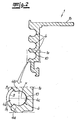
- a profile strip device which is composed of a first profile strip 1 and a second profile strip 2.
- the profiled strip device or the two profiled strips 1, 2 can be advantageously produce SZ-profile strip devices, so openings in example walls, ceilings or floors covering frame, which are made of the two below in detail yet to be described profiled strips 1, 2.
- the profiled strip device from the two profiled strips 1, 2 is used inter alia for the production of a revision device, as shown in the Fig. 6 . 9 and 10 is shown.
- the profiled strip device of the two profiled strips 1, 2 thus serves to define the frame of the relevant inspection device.
- the second profiled strip 2 can be connected to the first profiled strip 1, namely detachably.
- the second profile strip 2 has at least one fastening head 3, which is received in at least one receptacle 4 on the first profile strip 1 or engages in said receptacle 4.
- the first profiled strip 1 is equipped with several receptacles 4 (actually up to four receptacles 4 are realized).
- the individual receptacles 4 in the first profile strip 1 each along a leg 1a of this first profile strip. 1
- leg 1a another leg 1b of the first profile strip 1 is connected.
- Both legs 1a, 1b of the first profiled strip 1 are substantially perpendicular to each other, so that the profiled strip 1 is designed in cross section largely L-shaped, which of course does not necessarily have to be realized.
- the leg 1b of the profile strip 1 may serve to accommodate a planking, cladding, etc., or serves as a support therefor. In the embodiment of the Fig. 6 . 9 and 10 However, said leg 1 b acts as a limit stop in an opening.
- the second profiled strip 2 which is also and regularly used as a support for a cladding or a planking 5, as the Fig. 6 . 9 and 10 represent.
- the relevant planking 5, for example, even later on the said leg or the second profile strip 2 can be set, and without problems, the invention provides that the second profile bar 2 with its mounting head 3 inserted in the mounting position in the associated receptacle 4 and then pivoted into a working position and this case is simultaneously fixed relative to the first profile strip 1.
- the installation position of the second profile strip 2 corresponds to the in Fig. 1 and 7 illustrated lower layer.
- the position shown above the second profile strip 2 belongs to their working position.
- the fastening head 3 is in strictestitude about a fastening head profile 3, whereas the receptacle 4 is designed as a receiving groove 4. For this reason, the mounting head or the mounting profile 3 in the recording respectively on be inserted 4 in the installation position. This corresponds to the insertion position.
- the working position is also referred to below as a clamping position (in comparison to the insertion position).
- Both the insertion position and the clamping position correspond to a certain angle a between the second profiled strip 2 and the leg 1a of the first profiled strip 1 having the receptacle (s) 4.
- both the mounting head 3 and the receptacle 4 are each formed eccentrically in cross section.
- the mounting head 3 has two bulges 6, which are diametrically opposed to a center 7 of a cross-sectional circular area 18.
- the cross-sectional circular area 18 is indicated by dashed lines and corresponds to an (imaginary) circular cross-section of the mounting head 3. This deviates from the mounting head 3, because at this point the already mentioned bulges 6 are realized, which are substantially diametrically opposed to the center 7 , In this case, a bulge 6 is formed on a head and the other bulge 6 at one foot of two head legs 3a, 3b, of which the fastening head 3 is composed. Between the two head legs 3a, 3b, a central gap 3c is provided.
- the fastening head 3 has the two head legs 3 a, 3 b or they define the fastening head 3, the fastening head 3 is designed to be elastic with respect to its shape.
- the two Receiving legs 4a, 4b include a substantially circular or eccentric opening 4c between them. In this circular opening 4c of the mounting head 3 is received.
- the two receiving legs 4a, 4b define an insertion gap 4d for the fastening head 3. It can be seen that the insertion gap 4d sweeps over an arc angle ⁇ in the range between approximately 40 ° and 120 °, in the exemplary embodiment between 70 ° and 90 °.
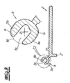
- the arc angle ⁇ is composed of two partial angles ⁇ 1 and ⁇ 2 (cf. Fig. 2 ).
- both the mounting head 3 and the receptacle enclosing it 4 of each leg 3a, 3b; 4a, 4b are constructed and the rest of the respective profile strip 1, 2 is made of metal, both the mounting head 3 and the receptacle 4 can change elastically with respect to their shape ver. This makes it possible that not only the mounting head 3 is fixed in the receptacle 4 in the working position or clamping position due to the bulges 6, sondem that this fix when changing from the clamping position into the insertion position can also be canceled. That is, the two profile strips 1, 2 are detachably connected to each other and can be reproducibly transferred to the insertion position and the clamping position. It should be additionally considered that the receptacle 4 is equipped with a bulge 10, the opposite of the insertion 4d finds an arrangement and ultimately provides for the eccentric nature of the opening 4c.
- the second bulge 6 of the fastening head 3 is arranged in the insertion gap 4d and does not engage in the receptacle 4. If now the second profile strip 2 is transferred from its installation position or insertion position in the working position or clamping position, the bulge 6 leaves the head leg 3b, the recess or bulge 10 in the receptacle 4. At the same time dives the second bulge 6 of the mounting head 3 on the head leg 3a in the recording 4 increasingly. As a result, the two bulges 6 of the mounting head 3 now ensure that the second profile strip 2 is clamped with its mounting head 3 in the receptacle 4 of the first profile strip 1.
- a similar procedure and function is for the modified embodiment of the Fig. 4 and 5 observed.
- the insertion position or installation position is now arranged.
- the second profile strip 2 is fixed both in the working position and in the mounting position each clamping with its mounting head 3 in the respective recording 4.
- the mounting head 3 in the embodiment according to the Fig. 4 and 5 over a total of four bulges 6, which are opposite each other in pairs substantially diametrically compared to the center 7.
- the four bulges 6 are respectively formed at the head and at the foot of the two head legs 3a, 3b.
- the bulges 6 deploy in the (middle) installation position Fig. 4 in the associated receptacle 4 only on the head side of the two head legs 3a, 3b effect.
- the two bulges 6 at the foot of the two head legs 3a, 3b free.
- the bulge 6 at the foot of the head leg 3a ensures the required clamping action.
- the second profile strip 2 is pivoted at the transition from the mounting position to the working position by almost 90 °.
- the second profile strip is in the installed position or insertion position in an intermediate position between the working position and the mounting position.
- This revision device is equipped with a revision frame 11 and an insertable into the inspection frame 11 inspection cover 12.
- Both the inspection frame 11 and the inspection cover 12 are each equipped with a frame profile 13 respectively 14 for receiving the planking 5.
- the frame profile 13 of the inspection frame 11 from the above-described profiled strip device according to the Fig. 1 to 3 or 4 and 5 built.
- the frame profile 13 is composed of the first profile strip 1 and the second profile strip 2.
- planks 5 of different thickness S can be fixed to the second profiled strip 2 or a fastening device realized in this way.
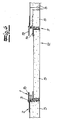
- a profile strip device is shown, which is composed again of a first profile strip 1 and a second profile strip 2.
- the frame profile strip devices or frames are defined from the two profiled strips 1, 2, which will be described below in detail.
- the profiled strip device from the two profiled strips 1, 2 is used inter alia for producing a revision device, as described in the Fig. 9 is shown.
- the profiled strip frontage serves according to the FIGS. 7 and 8 from the two moldings 1, 2 so to define the scope of the relevant revision device. Not shown is the further possibility to produce the cover of the inspection device by means of the profile strips 1, 2.
- the second profiled strip 2 can be connected to the first profiled strip 1, namely substantially positive and detachable.
- the second profiled strip 2 has the at least one fastening head 3 which is received in a form-fitting and releasable manner in at least one receptacle 4 on the first profiled strip 1 or which engages in said receptacle 4.
- the first profile strip 1 with a plurality of receptacles 4 (actually four receptacles 4 in the Fig. 7 realized) equipped.
- the further leg 1b of the first profile strip 1 is connected. Both legs 1a, 1b of the first profiled strip 1 are substantially perpendicular to each other, so that the first profiled strip 1 is designed in cross section largely L-shaped. Of course this is not mandatory.
- the leg 1b of the profile strip 1 may serve as usual to accommodate a planking, trim, etc., or serves as a support for this purpose. In the embodiment of the Fig. 9 said leg 1 b acts as a limit stop in an opening, for a revision cover 12 with frame profile 14th
- the second profiled strip 2 which is also and regularly used as a support for a cladding or a planking 5, as the Fig. 9 represents.
- the four along the leg 1a in the realization of a revision device after Fig. 9 superimposed receptacles 4 sure that the planking 5 in question can be adjusted in height adjustable by means of the second profile strip 2 to the first profile strip 1.
- the panel 5 in question for example, even later on the said leg or the second profile strip 2 can be set, and indeed without problems, the invention provides that the second profile strip 2 with its mounting head 3 substantially positive and releasable in its installed position in the Recording 4 engages.
- the mounting head 3 is elastically resilient and is composed for this purpose in the embodiment of the two spaced-apart head legs 3a, 3b together.
- a central gap 3c may be provided between the two head legs 3a, 3b (cf. Fig. 8 ).
- the fastening head 3 has the two head legs 3a, 3b and / or these define the fastening head 3, the fastening head 3 is resiliently yielding with regard to its shape.
- the two head legs 3a, 3b are connected to a common base or a leg 2a of the second profiled strip 2.
- the leg 2a of the second profiled strip 2 serves to fix the planking 5 (cf. Fig. 9 ).
- the two head legs 3a, 3b protrude at an angle from the base or the leg 2a, for example, in each case at right angles to the base or the leg 2a. This causes the two heads legs 3a, 3b arranged opposite each other and have between them an angle of about 180 °.
- the two head legs 3a, 3b of the mounting head 3 are designed differently, as can be seen in particular in the enlarged view Fig. 8 recognizes.
- one head leg 3a is designed as a hook leg 3a and the other head leg 3b as a locking leg 3b.
- both the hook leg 3a and the latching leg 3b engage behind a respective projection 16 in the receptacle 4 of the first profile strip, in the installation position shown in solid lines Fig. 7 ,
- the receptacle 4 is composed again of the two receiving legs 4a, 4b and an opening 4c, which acts as a receiving base 4c.
- the receptacle 4 For the maintenance of the mounting head 3 in the receptacle 4 primarily provide the two receiving legs 4a, 4b in conjunction with the two opposing projections 16.
- the insertion opening 17 has a cross-section or a width B.
- the fastening head 3 has a diameter or a spacing A of the ends of the two opposing limbs 3a, 3b.
- the mounting head 3 is securely held in the receptacle 4 and clamped, is that the distance B of the projections 16 is smaller than the distance A of the ends of the head legs 3a, 3b configured, ie A > B applies.
- the two head limbs 3a, 3b can be compressed and consequently their distance A (temporarily and elastically resilient) decreases, namely, until the distance A substantially corresponds to the distance B between the two projections 16 relative to one another.
- This compression or compression of the mounting head 3 is brought about in the embodiment so that the mounting head 3 with its two head legs 3 a, 3 b is inserted obliquely into the receptacle 4.
- the hook leg 3a engages behind the lower projection 16 of the receptacle 4.
- the second profiled strip 2 is pivoted in the direction of the arrow, ensures a guide arc 8 on the mounting head 3 and the end of the locking leg 3b for the necessary compression of the mounting head 3 and a Vierring réelle the distance A.
- the guide sheet 8 slides on the upper projection 16 of Receiving 4 while passing through the insertion opening 17 along, so that the two head legs 3a, 3b pass with slight reduction of their gap 3c between the insertion 17. As soon as both head legs 3a, 3b have passed the two projections 16, they are able to spring up again to their original dimensions.
- both the hook leg 3a and the locking leg 3b engage behind the associated projections 16 on both sides of the receptacle 4.
- the procedure described is of course only to be understood as an example, since the mounting head 3 can also be pressed frontally into the receptacle 4 and clipped into it.
- the two head legs 3a, 3b arranged substantially at right angles to the leg 2a or the base 2a are connected to a V-web 9.
- This V-web 9 defines with its two V-legs 9a, 9b, the gap 3c between the two head legs 3a, 3b, which is also designed V-shaped.
- the two head legs 3a, 3b are respectively connected on the head side to the associated V-legs 9a, 9b.
- the V-legs 9a, 9b are in turn connected to the base or leg 2a of the second profiled strip 2 on the foot side.
- the two profiled strips 1, 2 are continuous metal profiled strips.
- the receptacles 4 each form receiving grooves 4.
- the exemplary use of the profile strip device according to the FIGS. 7 and 8 in the realization of a revision device clearly.
- the revision device is equipped with the revision frame 11 and the inspection cover 11 which can be used in the revision frame 11.
- Both the inspection frame 11 and the inspection cover 12 are each equipped with the frame profile 13 respectively 14 for receiving the planking 5.
- the frame profile 13 of the inspection frame 11 from the above-described profiled strip device according to the FIGS. 7 and 8 built up.
- the frame profile 13 is composed of the first profile strip 1 and the second profile strip 2 as described.
- planks 5 of different thickness S can be fixed to the second profiled strip 2 or a fastening device realized in this way, as in the right-hand part of the Fig. 9 is shown.
- a revision device or a profile strip device which serves in its basic structure to release an opening 15 in a wall, ceiling and / or floor panel 19 as needed to wait behind the panel in question 19 installations can, these to install, repair etc .
- the illustrated revision device is in its basic structure of the inspection frame 11 and a frame inside in this revision frame 11 usable inspection cover 12 together.
- the inspection cover 12 is formed in cross-section L-shaped and has the associated frame profile 14. A plurality of legs of the frame profile 14 are circumferentially connected to each other and form the inspection cover 12. In the interior of the inspection cover 12, a cover panel 5 or generally the planking 5 is added, which is enclosed by the peripheral frame profile 14.
- the inspection frame 11 also has a circumferential and the opening 15 bordering frame profile 13, which corresponds to the first profile strip 1 and in the same way - as the inspection cover 12 - is designed in cross-section L-shaped. Like the cover profile 14, so the frame profile 13 of the inspection frame 11 is adapted to receive a panel 5, namely the planking 5, which is received in the frame section 13.
- the frame-side planking 5 can be designed with different planking thicknesses S.
- a fastening device 2 in the form of the second profiled strip 2 for fixing the planking 5 in question is provided on the frame profile 13 of the inspection frame 11 or the first profiled strip 1.
- the fastening device 2 is depth adjustable in the embodiment connected to the inspection frame 11. In this way, the position of the fastening device 2 in the frame depth direction T can be varied.
- the fastening device 2 is shown in the Fig. 11 to 14 and not limiting to a bar, which is basically constructed in two parts and has the mounting head 3 and a support leg or leg 2a.
- the fastening device 2 or the second profile strip 2 engages with its mounting head 3 positively and at the same time releasably in the at least one receptacle 4 on the frame section 13 of the inspection frame 11 and in the first profile strip 1.
- the fastening device 2 can also be connected to the frame profile 14 of the inspection cover 12. However, this is not shown, because usually the revision frame 11 is set up to accommodate different panel thicknesses S.
- the associated receptacle 4 has a corresponding shape to afford the positive retention of the mounting head 3 in the receptacle 4 to make.
- the receptacle 4 in the exemplary embodiment is a receiving groove which follows the longitudinal extension of the fastening device 2 designed as a strip or is adapted to it.
- the fastening device 2 (in its working position) is aligned essentially at right angles to the frame profile 13.
- the fastening device 2 extends perpendicularly or at right angles to the longer L-leg 1a of the cross-sectionally L-shaped frame profile 13, whereas the shorter L-leg 1b extends parallel to the fastening device 2.
- the reference numeral 1c denotes in the 10 to 14 a visible edge 1 c of the inspection frame 11, with which the planking 5, together with optionally a surface covering surface flush.
- planking 5 rests overall and almost flat on the support leg 2a of the fastening device 2.
- An additional profiling 2b may at this point ensure that an adhesive applied to the support leg 2a or generally the fastening device 2 adhesive agent after curing keeps the planking 5 captive.
- the planking 5 can also be connected to the support leg 2a in question by means of one or more fastening means 20.
- the fastener 20 may be a screw, a rivet or the like.
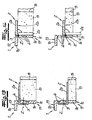
- two receptacles 4 are provided in the frame profile 13 of the inspection frame 11 in order to determine the fastening device 2 depending on the planking thickness S of the planking 5 enclosing it.
- the multiple receptacles 4 are placed in the frame depth direction T one behind the other and parallel to one another in the longitudinal direction of the frame profile 13.
- the embodiments of the Fig. 12 to 14 is common that the fastening device 2 can be set in at least two different functional positions on the inspection frame 11, respectively, the frame profile 13. These different functional positions correspond to the examples in the examples Fig. 12 and 13 to different planking strengths S or take this account.
- the embodiment according to Fig. 14 uses the various functional positions of the fastening device 2 to the assembly of the inspection frame 11 in the receiving him To facilitate opening 15 in the panel 19. In this case, the fastening device 2 engages in the cases described in each case in one and the same receptacle 4 a.
- the fastening device 2 rotate about an axis Z, by 180 °.
- the axis Z in question runs perpendicular to the frame profile 13 of the inspection frame 11 or perpendicular to its longer L-leg 1a.
- the fastening device 2 is designed overall L-shaped, this rotation about the axis Z results in that the support leg 2a of the fastening device 2 has a different distance C compared to the visible edge 1c of the inspection frame 11, in the example, the two different panel thicknesses S of the planking 5 record.
- the fastening device 2 also occupy two functional positions by a rotation again this time about another axis Z ', which in this case extends in the longitudinal extent of the frame profile 13 and its longer L-leg 1a and also in the longitudinal extent of the groove-like receptacle 4.
- the fastening device 2 or its support leg 2a makes a 90 "rotation, in this way the fastening device or the second profile strip 2 can be folded on the inside of the inspection frame 11 (assembly position) and folded away from it (working position).
- the inspection frame 11 can be easily introduced into the opening 15 together with the fastening device 2.
- the fastening device 2 is folded down into the working position and is now on the planking 5 on.
- the fastening device 2 after folding or pivoting about the axis Z ' can be locked by 90 ° in the receptacle 4 to prevent after insertion of the inspection frame 11 in the opening 15 a renewed folding down the fastening device 2 (working position).
- the determination of the planking 5 with the different planking thickness S always takes place at the support leg 2a, in which case an adhesive agent applied to the profiling 2b additionally or solely provides the required connection.
- the adaptation to the different planking of the different planking thicknesses S takes place - as in the variant according to the Fig. 11 - In such a way that the fastening device 2 with its mounting head 3 in the corresponding Beplankungsstar S corresponding receptacle 4 is set positively and releasably.
Landscapes
- Architecture (AREA)
- Engineering & Computer Science (AREA)
- Civil Engineering (AREA)
- Structural Engineering (AREA)
- Coating With Molten Metal (AREA)
- Roof Covering Using Slabs Or Stiff Sheets (AREA)
- Registering, Tensioning, Guiding Webs, And Rollers Therefor (AREA)
- Polarising Elements (AREA)
- Conveying And Assembling Of Building Elements In Situ (AREA)
- Mutual Connection Of Rods And Tubes (AREA)
- Length-Measuring Instruments Using Mechanical Means (AREA)
- Reinforcement Elements For Buildings (AREA)
- Tents Or Canopies (AREA)
- Bending Of Plates, Rods, And Pipes (AREA)
- Connection Of Plates (AREA)
Priority Applications (3)
| Application Number | Priority Date | Filing Date | Title |
|---|---|---|---|
| PL09709217T PL2240651T3 (pl) | 2008-02-08 | 2009-02-06 | Zespół listew profilowych |
| SI200930156T SI2240651T1 (sl) | 2008-02-08 | 2009-02-06 | Priprava s profilnimi letvami |
| CY20121100153T CY1112931T1 (el) | 2008-02-08 | 2012-02-15 | Διαταξη ραβδων προφιλ |
Applications Claiming Priority (4)
| Application Number | Priority Date | Filing Date | Title |
|---|---|---|---|
| DE200820001831 DE202008001831U1 (de) | 2008-02-08 | 2008-02-08 | Revisionsvorrichtung |
| DE200820010542 DE202008010542U1 (de) | 2008-08-07 | 2008-08-07 | Profilleistenvorrichtung |
| DE202008011882U DE202008011882U1 (de) | 2008-09-05 | 2008-09-05 | Profilleistenvorrichtung |
| PCT/EP2009/000826 WO2009098067A1 (de) | 2008-02-08 | 2009-02-06 | Profilleistenvorrichtung |
Publications (2)
| Publication Number | Publication Date |
|---|---|
| EP2240651A1 EP2240651A1 (de) | 2010-10-20 |
| EP2240651B1 true EP2240651B1 (de) | 2011-11-16 |
Family
ID=40602503
Family Applications (1)
| Application Number | Title | Priority Date | Filing Date |
|---|---|---|---|
| EP09709217A Active EP2240651B1 (de) | 2008-02-08 | 2009-02-06 | Profilleistenvorrichtung |
Country Status (10)
| Country | Link |
|---|---|
| EP (1) | EP2240651B1 (pl) |
| AT (1) | ATE533905T1 (pl) |
| CY (1) | CY1112931T1 (pl) |
| DK (1) | DK2240651T3 (pl) |
| ES (1) | ES2377453T3 (pl) |
| HR (1) | HRP20120112T1 (pl) |
| PL (1) | PL2240651T3 (pl) |
| PT (1) | PT2240651E (pl) |
| SI (1) | SI2240651T1 (pl) |
| WO (1) | WO2009098067A1 (pl) |
Families Citing this family (2)
| Publication number | Priority date | Publication date | Assignee | Title |
|---|---|---|---|---|
| DE202010013208U1 (de) | 2010-12-23 | 2011-02-24 | Knauf Gips Kg | Trockenbauwand |
| JP6366096B2 (ja) * | 2014-08-02 | 2018-08-01 | 株式会社サヌキ | 点検口の外枠固定装置 |
Family Cites Families (13)
| Publication number | Priority date | Publication date | Assignee | Title |
|---|---|---|---|---|
| US4139972A (en) | 1975-07-18 | 1979-02-20 | Hiromitsu Naka | Anchoring device |
| US5363616A (en) * | 1992-08-13 | 1994-11-15 | Diston Industries, Inc. | Adjustable corner mullion for joining building panels |
| JP3145607B2 (ja) * | 1995-05-23 | 2001-03-12 | 理研アルミ建材株式会社 | 点検口 |
| JP3155171B2 (ja) * | 1995-07-07 | 2001-04-09 | 理研アルミ建材株式会社 | 天井点検口 |
| JP2001279920A (ja) * | 2000-03-29 | 2001-10-10 | Naka Ind Ltd | 天井点検口の蓋体 |
| DE20015244U1 (de) * | 2000-09-01 | 2001-02-22 | Carl Prinz GmbH & Co. Metallwarenfabrik, 47574 Goch | Profilschienensystem für Bodenbeläge |
| JP2003120013A (ja) * | 2001-10-16 | 2003-04-23 | Riken Alum Kenzai Kk | 天井点検口の吊下構造 |
| GB2417979A (en) * | 2004-09-11 | 2006-03-15 | Howe Green Limited | Hinged wall access panel |
| EP1903161B1 (de) | 2006-09-18 | 2011-05-18 | Christoph Langenhorst | Revisionsvorrichtung mit einem Revisionsrahmen und einem Revisionsdeckel |
| DE202007001538U1 (de) | 2007-02-02 | 2008-06-19 | Effizien-Zen Gmbh | Revisionsvorrichtung, insbesondere Revisionsabdeckung |
| DE202008010542U1 (de) * | 2008-08-07 | 2008-10-23 | Knauf Alutop Gmbh | Profilleistenvorrichtung |
| DE202008011882U1 (de) * | 2008-09-05 | 2008-11-27 | Knauf Alutop Gmbh | Profilleistenvorrichtung |
| DE202008001831U1 (de) | 2008-02-08 | 2008-04-30 | Knauf Alutop Gmbh | Revisionsvorrichtung |
-
2009
- 2009-02-06 SI SI200930156T patent/SI2240651T1/sl unknown
- 2009-02-06 PL PL09709217T patent/PL2240651T3/pl unknown
- 2009-02-06 HR HR20120112T patent/HRP20120112T1/hr unknown
- 2009-02-06 PT PT09709217T patent/PT2240651E/pt unknown
- 2009-02-06 DK DK09709217.5T patent/DK2240651T3/da active
- 2009-02-06 AT AT09709217T patent/ATE533905T1/de active
- 2009-02-06 WO PCT/EP2009/000826 patent/WO2009098067A1/de not_active Ceased
- 2009-02-06 ES ES09709217T patent/ES2377453T3/es active Active
- 2009-02-06 EP EP09709217A patent/EP2240651B1/de active Active
-
2012
- 2012-02-15 CY CY20121100153T patent/CY1112931T1/el unknown
Also Published As
| Publication number | Publication date |
|---|---|
| WO2009098067A1 (de) | 2009-08-13 |
| PL2240651T3 (pl) | 2012-07-31 |
| PT2240651E (pt) | 2012-02-27 |
| SI2240651T1 (sl) | 2012-05-31 |
| ATE533905T1 (de) | 2011-12-15 |
| ES2377453T3 (es) | 2012-03-27 |
| CY1112931T1 (el) | 2016-04-13 |
| HRP20120112T1 (hr) | 2012-04-30 |
| EP2240651A1 (de) | 2010-10-20 |
| DK2240651T3 (da) | 2012-02-27 |
Similar Documents
| Publication | Publication Date | Title |
|---|---|---|
| EP3235983A1 (de) | Schiebetüranlage und schienenvorrichtung | |
| DE202006021264U1 (de) | Tür- und Fensterrahmen mit einem hinterschnittenen Eingriffsbereich für eine Getriebeeinheit | |
| DE102020100493A1 (de) | Torpfosten für Sichtschutz | |
| DE102007053340A1 (de) | Eckumlenkung für ein Treibstangenbeschlagsystem für einen Fenster- oder Türflügel | |
| EP3071896A1 (de) | Haltevorrichtung für ein gehäuse und verfahren zur montage des gehäuses unter verwendung der haltevorrichtung | |
| EP2240651A1 (de) | Profilleistenvorrichtung | |
| DE202008010542U1 (de) | Profilleistenvorrichtung | |
| DE202022101269U1 (de) | Befestigungssystem und Abdeckeinheit | |
| DE102016125819A1 (de) | Hinterfütterungsvorrichtung sowie damit versehene Umfassungszarge | |
| DE102005044322B4 (de) | Haltekonstruktion für Fassadenplatten, sowie Gebäudefassade | |
| DE202015102101U1 (de) | Schließblech, Anordnung mit einem solchen Schließblech und Türzarge mit einem solchen Schließblech | |
| DE202008001831U1 (de) | Revisionsvorrichtung | |
| EP3235984B1 (de) | Beschlag für ein fenster, verfahren zum herstellen des beschlags sowie entsprechendes fenster | |
| EP4526530B1 (de) | Befestigungssystem zur befestigung einer fassadenplatte an einer c-profilschiene und verfahren zur befestigung der fassadenplatte mit dem befestigungssystem | |
| DE202020100944U1 (de) | Zarge sowie Türsystem mit einer solchen Zarge | |
| DE202009012416U1 (de) | Befestigungsvorrichtung zur Anordnung einer Torzarge an einer Wand | |
| EP1830011B1 (de) | Bewehrungshalter | |
| EP2354697A2 (de) | Befestigungs-Rahmen für ein Lüftungsgitter | |
| EP2182157B1 (de) | Blende für einen Spalt zwischen einer Tür- oder Torzarge und Laibung | |
| EP3561199A1 (de) | Verbindungselement für schalungen und verfahren um schalungselemente zu verbinden | |
| DE102009003910A1 (de) | Tragschiene für eine Vorrichtung zur Halterung von Wandplatten an einer Wand sowie Fassadenbekleidung | |
| EP3636848B1 (de) | Keilelement, abstandhalter mit mindestens einem solchen keilelement, positioniervorrichtung mit einem solchen abstandhalter und verfahren zur positionierung von wandschalungen | |
| WO2003087508A1 (de) | Kopplungsvorrichtung | |
| DE69500536T2 (de) | Verriegelungsvorrichtung für den halbbefestigten Flügel eines Fensters mit zwei Flügeln | |
| AT508577B1 (de) | Treibstangenbeschlag |
Legal Events
| Date | Code | Title | Description |
|---|---|---|---|
| PUAI | Public reference made under article 153(3) epc to a published international application that has entered the european phase |
Free format text: ORIGINAL CODE: 0009012 |
|
| 17P | Request for examination filed |
Effective date: 20100812 |
|
| AK | Designated contracting states |
Kind code of ref document: A1 Designated state(s): AT BE BG CH CY CZ DE DK EE ES FI FR GB GR HR HU IE IS IT LI LT LU LV MC MK MT NL NO PL PT RO SE SI SK TR |
|
| AX | Request for extension of the european patent |
Extension state: AL BA RS |
|
| 17Q | First examination report despatched |
Effective date: 20110114 |
|
| DAX | Request for extension of the european patent (deleted) | ||
| GRAP | Despatch of communication of intention to grant a patent |
Free format text: ORIGINAL CODE: EPIDOSNIGR1 |
|
| GRAS | Grant fee paid |
Free format text: ORIGINAL CODE: EPIDOSNIGR3 |
|
| GRAA | (expected) grant |
Free format text: ORIGINAL CODE: 0009210 |
|
| AK | Designated contracting states |
Kind code of ref document: B1 Designated state(s): AT BE BG CH CY CZ DE DK EE ES FI FR GB GR HR HU IE IS IT LI LT LU LV MC MK MT NL NO PL PT RO SE SI SK TR |
|
| REG | Reference to a national code |
Ref country code: GB Ref legal event code: FG4D Free format text: NOT ENGLISH |
|
| REG | Reference to a national code |
Ref country code: CH Ref legal event code: EP |
|
| REG | Reference to a national code |
Ref country code: IE Ref legal event code: FG4D Free format text: LANGUAGE OF EP DOCUMENT: GERMAN |
|
| REG | Reference to a national code |
Ref country code: HR Ref legal event code: TUEP Ref document number: P20120112 Country of ref document: HR Ref country code: DE Ref legal event code: R096 Ref document number: 502009001950 Country of ref document: DE Effective date: 20120202 |
|
| REG | Reference to a national code |
Ref country code: RO Ref legal event code: EPE |
|
| REG | Reference to a national code |
Ref country code: CH Ref legal event code: NV Representative=s name: KELLER & PARTNER PATENTANWAELTE AG |
|
| REG | Reference to a national code |
Ref country code: NL Ref legal event code: T3 |
|
| REG | Reference to a national code |
Ref country code: DK Ref legal event code: T3 Ref country code: PT Ref legal event code: SC4A Free format text: AVAILABILITY OF NATIONAL TRANSLATION Effective date: 20120214 |
|
| REG | Reference to a national code |
Ref country code: SE Ref legal event code: TRGR |
|
| REG | Reference to a national code |
Ref country code: CH Ref legal event code: PFA Owner name: KNAUF ALUTOP GMBH Free format text: KNAUF ALUTOP GMBH#OVERWEG 14#59494 SOEST (DE) -TRANSFER TO- KNAUF ALUTOP GMBH#AM BAHNHOF 7#97346 IPHOFEN (DE) |
|
| RAP2 | Party data changed (patent owner data changed or rights of a patent transferred) |
Owner name: KNAUF ALUTOP GMBH |
|
| REG | Reference to a national code |
Ref country code: ES Ref legal event code: FG2A Ref document number: 2377453 Country of ref document: ES Kind code of ref document: T3 Effective date: 20120327 |
|
| REG | Reference to a national code |
Ref country code: NO Ref legal event code: T2 Effective date: 20111116 |
|
| REG | Reference to a national code |
Ref country code: HR Ref legal event code: PNAN Ref document number: P20120112 Country of ref document: HR Owner name: KNAUF ALUTOP GMBH, DE |
|
| REG | Reference to a national code |
Ref country code: GR Ref legal event code: EP Ref document number: 20120400369 Country of ref document: GR Effective date: 20120322 |
|
| PG25 | Lapsed in a contracting state [announced via postgrant information from national office to epo] |
Ref country code: IS Free format text: LAPSE BECAUSE OF FAILURE TO SUBMIT A TRANSLATION OF THE DESCRIPTION OR TO PAY THE FEE WITHIN THE PRESCRIBED TIME-LIMIT Effective date: 20120316 |
|
| REG | Reference to a national code |
Ref country code: HR Ref legal event code: T1PR Ref document number: P20120112 Country of ref document: HR |
|
| REG | Reference to a national code |
Ref country code: HU Ref legal event code: AG4A Ref document number: E012814 Country of ref document: HU |
|
| REG | Reference to a national code |
Ref country code: SK Ref legal event code: T3 Ref document number: E 11357 Country of ref document: SK |
|
| REG | Reference to a national code |
Ref country code: EE Ref legal event code: FG4A Ref document number: E006605 Country of ref document: EE Effective date: 20120215 |
|
| PGFP | Annual fee paid to national office [announced via postgrant information from national office to epo] |
Ref country code: IT Payment date: 20120228 Year of fee payment: 4 Ref country code: HR Payment date: 20120203 Year of fee payment: 4 |
|
| REG | Reference to a national code |
Ref country code: PL Ref legal event code: T3 |
|
| PLBE | No opposition filed within time limit |
Free format text: ORIGINAL CODE: 0009261 |
|
| STAA | Information on the status of an ep patent application or granted ep patent |
Free format text: STATUS: NO OPPOSITION FILED WITHIN TIME LIMIT |
|
| PG25 | Lapsed in a contracting state [announced via postgrant information from national office to epo] |
Ref country code: MC Free format text: LAPSE BECAUSE OF NON-PAYMENT OF DUE FEES Effective date: 20120229 |
|
| 26N | No opposition filed |
Effective date: 20120817 |
|
| REG | Reference to a national code |
Ref country code: DE Ref legal event code: R097 Ref document number: 502009001950 Country of ref document: DE Effective date: 20120817 |
|
| REG | Reference to a national code |
Ref country code: HR Ref legal event code: ODRP Ref document number: P20120112 Country of ref document: HR Payment date: 20130124 Year of fee payment: 5 |
|
| PGFP | Annual fee paid to national office [announced via postgrant information from national office to epo] |
Ref country code: MK Payment date: 20130228 Year of fee payment: 5 |
|
| PGFP | Annual fee paid to national office [announced via postgrant information from national office to epo] |
Ref country code: LU Payment date: 20130221 Year of fee payment: 5 |
|
| PGFP | Annual fee paid to national office [announced via postgrant information from national office to epo] |
Ref country code: BG Payment date: 20130213 Year of fee payment: 5 Ref country code: NO Payment date: 20130214 Year of fee payment: 5 Ref country code: HU Payment date: 20130301 Year of fee payment: 5 Ref country code: RO Payment date: 20130201 Year of fee payment: 5 Ref country code: DK Payment date: 20130218 Year of fee payment: 5 Ref country code: LT Payment date: 20130123 Year of fee payment: 5 Ref country code: ES Payment date: 20130227 Year of fee payment: 5 Ref country code: IE Payment date: 20130219 Year of fee payment: 5 Ref country code: CH Payment date: 20130220 Year of fee payment: 5 Ref country code: SE Payment date: 20130219 Year of fee payment: 5 Ref country code: EE Payment date: 20130213 Year of fee payment: 5 Ref country code: FI Payment date: 20130213 Year of fee payment: 5 |
|
| PGFP | Annual fee paid to national office [announced via postgrant information from national office to epo] |
Ref country code: CY Payment date: 20130128 Year of fee payment: 5 Ref country code: PL Payment date: 20130124 Year of fee payment: 5 Ref country code: NL Payment date: 20130219 Year of fee payment: 5 Ref country code: GR Payment date: 20130222 Year of fee payment: 5 Ref country code: LV Payment date: 20130213 Year of fee payment: 5 Ref country code: BE Payment date: 20130220 Year of fee payment: 5 Ref country code: SI Payment date: 20130129 Year of fee payment: 5 |
|
| PGFP | Annual fee paid to national office [announced via postgrant information from national office to epo] |
Ref country code: PT Payment date: 20120214 Year of fee payment: 5 |
|
| PG25 | Lapsed in a contracting state [announced via postgrant information from national office to epo] |
Ref country code: MT Free format text: LAPSE BECAUSE OF FAILURE TO SUBMIT A TRANSLATION OF THE DESCRIPTION OR TO PAY THE FEE WITHIN THE PRESCRIBED TIME-LIMIT Effective date: 20111116 |
|
| REG | Reference to a national code |
Ref country code: HR Ref legal event code: PBON Ref document number: P20120112 Country of ref document: HR Effective date: 20140206 |
|
| REG | Reference to a national code |
Ref country code: PT Ref legal event code: MM4A Free format text: LAPSE DUE TO NON-PAYMENT OF FEES Effective date: 20140806 |
|
| BERE | Be: lapsed |
Owner name: KNAUF ALUTOP G.M.B.H. Effective date: 20140228 |
|
| REG | Reference to a national code |
Ref country code: NL Ref legal event code: V1 Effective date: 20140901 |
|
| REG | Reference to a national code |
Ref country code: LT Ref legal event code: MM4D Effective date: 20140206 |
|
| REG | Reference to a national code |
Ref country code: DK Ref legal event code: EBP Effective date: 20140228 |
|
| PG25 | Lapsed in a contracting state [announced via postgrant information from national office to epo] |
Ref country code: LU Free format text: LAPSE BECAUSE OF NON-PAYMENT OF DUE FEES Effective date: 20140206 |
|
| REG | Reference to a national code |
Ref country code: CH Ref legal event code: PL Ref country code: SE Ref legal event code: EUG |
|
| REG | Reference to a national code |
Ref country code: EE Ref legal event code: MM4A Ref document number: E006605 Country of ref document: EE Effective date: 20140228 |
|
| REG | Reference to a national code |
Ref country code: GR Ref legal event code: ML Ref document number: 20120400369 Country of ref document: GR Effective date: 20140903 |
|
| PG25 | Lapsed in a contracting state [announced via postgrant information from national office to epo] |
Ref country code: NL Free format text: LAPSE BECAUSE OF NON-PAYMENT OF DUE FEES Effective date: 20140901 Ref country code: EE Free format text: LAPSE BECAUSE OF NON-PAYMENT OF DUE FEES Effective date: 20140228 Ref country code: LI Free format text: LAPSE BECAUSE OF NON-PAYMENT OF DUE FEES Effective date: 20140228 Ref country code: RO Free format text: LAPSE BECAUSE OF NON-PAYMENT OF DUE FEES Effective date: 20140206 Ref country code: CH Free format text: LAPSE BECAUSE OF NON-PAYMENT OF DUE FEES Effective date: 20140228 Ref country code: NO Free format text: LAPSE BECAUSE OF NON-PAYMENT OF DUE FEES Effective date: 20140228 Ref country code: LT Free format text: LAPSE BECAUSE OF NON-PAYMENT OF DUE FEES Effective date: 20140206 Ref country code: BG Free format text: LAPSE BECAUSE OF NON-PAYMENT OF DUE FEES Effective date: 20140930 Ref country code: GR Free format text: LAPSE BECAUSE OF NON-PAYMENT OF DUE FEES Effective date: 20140903 Ref country code: CY Free format text: LAPSE BECAUSE OF NON-PAYMENT OF DUE FEES Effective date: 20140206 Ref country code: FI Free format text: LAPSE BECAUSE OF NON-PAYMENT OF DUE FEES Effective date: 20140206 |
|
| PG25 | Lapsed in a contracting state [announced via postgrant information from national office to epo] |
Ref country code: SE Free format text: LAPSE BECAUSE OF NON-PAYMENT OF DUE FEES Effective date: 20140207 Ref country code: SI Free format text: LAPSE BECAUSE OF NON-PAYMENT OF DUE FEES Effective date: 20140207 Ref country code: LV Free format text: LAPSE BECAUSE OF NON-PAYMENT OF DUE FEES Effective date: 20140206 Ref country code: HR Free format text: LAPSE BECAUSE OF NON-PAYMENT OF DUE FEES Effective date: 20140206 |
|
| REG | Reference to a national code |
Ref country code: SI Ref legal event code: KO00 Effective date: 20141008 |
|
| REG | Reference to a national code |
Ref country code: IE Ref legal event code: MM4A |
|
| PG25 | Lapsed in a contracting state [announced via postgrant information from national office to epo] |
Ref country code: PT Free format text: LAPSE BECAUSE OF NON-PAYMENT OF DUE FEES Effective date: 20140806 |
|
| PG25 | Lapsed in a contracting state [announced via postgrant information from national office to epo] |
Ref country code: DK Free format text: LAPSE BECAUSE OF NON-PAYMENT OF DUE FEES Effective date: 20140228 Ref country code: BE Free format text: LAPSE BECAUSE OF NON-PAYMENT OF DUE FEES Effective date: 20140228 Ref country code: IE Free format text: LAPSE BECAUSE OF NON-PAYMENT OF DUE FEES Effective date: 20140206 |
|
| REG | Reference to a national code |
Ref country code: FR Ref legal event code: PLFP Year of fee payment: 7 |
|
| PG25 | Lapsed in a contracting state [announced via postgrant information from national office to epo] |
Ref country code: HU Free format text: LAPSE BECAUSE OF NON-PAYMENT OF DUE FEES Effective date: 20140207 |
|
| REG | Reference to a national code |
Ref country code: ES Ref legal event code: FD2A Effective date: 20150327 |
|
| REG | Reference to a national code |
Ref country code: AT Ref legal event code: MM01 Ref document number: 533905 Country of ref document: AT Kind code of ref document: T Effective date: 20140206 |
|
| PG25 | Lapsed in a contracting state [announced via postgrant information from national office to epo] |
Ref country code: ES Free format text: LAPSE BECAUSE OF NON-PAYMENT OF DUE FEES Effective date: 20140207 |
|
| PGFP | Annual fee paid to national office [announced via postgrant information from national office to epo] |
Ref country code: SK Payment date: 20150203 Year of fee payment: 7 Ref country code: CZ Payment date: 20150203 Year of fee payment: 7 |
|
| PG25 | Lapsed in a contracting state [announced via postgrant information from national office to epo] |
Ref country code: PL Free format text: LAPSE BECAUSE OF NON-PAYMENT OF DUE FEES Effective date: 20140206 Ref country code: AT Free format text: LAPSE BECAUSE OF NON-PAYMENT OF DUE FEES Effective date: 20140206 |
|
| PGFP | Annual fee paid to national office [announced via postgrant information from national office to epo] |
Ref country code: FR Payment date: 20150219 Year of fee payment: 7 |
|
| REG | Reference to a national code |
Ref country code: PL Ref legal event code: LAPE |
|
| PG25 | Lapsed in a contracting state [announced via postgrant information from national office to epo] |
Ref country code: IT Free format text: LAPSE BECAUSE OF NON-PAYMENT OF DUE FEES Effective date: 20140206 |
|
| REG | Reference to a national code |
Ref country code: SK Ref legal event code: MM4A Ref document number: E 11357 Country of ref document: SK Effective date: 20160206 |
|
| REG | Reference to a national code |
Ref country code: FR Ref legal event code: ST Effective date: 20161028 |
|
| PG25 | Lapsed in a contracting state [announced via postgrant information from national office to epo] |
Ref country code: CZ Free format text: LAPSE BECAUSE OF NON-PAYMENT OF DUE FEES Effective date: 20160206 Ref country code: SK Free format text: LAPSE BECAUSE OF NON-PAYMENT OF DUE FEES Effective date: 20160206 |
|
| PG25 | Lapsed in a contracting state [announced via postgrant information from national office to epo] |
Ref country code: FR Free format text: LAPSE BECAUSE OF NON-PAYMENT OF DUE FEES Effective date: 20160229 |
|
| PG25 | Lapsed in a contracting state [announced via postgrant information from national office to epo] |
Ref country code: MK Free format text: LAPSE BECAUSE OF NON-PAYMENT OF DUE FEES Effective date: 20140207 |
|
| P01 | Opt-out of the competence of the unified patent court (upc) registered |
Effective date: 20230822 |
|
| PGFP | Annual fee paid to national office [announced via postgrant information from national office to epo] |
Ref country code: GB Payment date: 20260227 Year of fee payment: 18 |
|
| PGFP | Annual fee paid to national office [announced via postgrant information from national office to epo] |
Ref country code: DE Payment date: 20260227 Year of fee payment: 18 |
|
| PGFP | Annual fee paid to national office [announced via postgrant information from national office to epo] |
Ref country code: TR Payment date: 20260127 Year of fee payment: 18 |