EP2240635B9 - Nadel zur übertragung von maschen von der nadel selbst auf benachbarte nadeln für strumpfstrickmaschinen oder ähnlichem - Google Patents
Nadel zur übertragung von maschen von der nadel selbst auf benachbarte nadeln für strumpfstrickmaschinen oder ähnlichem Download PDFInfo
- Publication number
- EP2240635B9 EP2240635B9 EP09706216A EP09706216A EP2240635B9 EP 2240635 B9 EP2240635 B9 EP 2240635B9 EP 09706216 A EP09706216 A EP 09706216A EP 09706216 A EP09706216 A EP 09706216A EP 2240635 B9 EP2240635 B9 EP 2240635B9
- Authority
- EP
- European Patent Office
- Prior art keywords
- shank
- needle
- lamina
- region
- head
- Prior art date
- Legal status (The legal status is an assumption and is not a legal conclusion. Google has not performed a legal analysis and makes no representation as to the accuracy of the status listed.)
- Not-in-force
Links
Images


Classifications
-
- D—TEXTILES; PAPER
- D04—BRAIDING; LACE-MAKING; KNITTING; TRIMMINGS; NON-WOVEN FABRICS
- D04B—KNITTING
- D04B35/00—Details of, or auxiliary devices incorporated in, knitting machines, not otherwise provided for
- D04B35/02—Knitting tools or instruments not provided for in group D04B15/00 or D04B27/00
- D04B35/04—Latch needles
Definitions
- the present invention relates to a needle for transferring stitches from the needle itself to adjacent needles for knitting machines for hosiery or the like.
- needles In the field of knitting machines for hosiery or the like, needles are known which are provided in order to allow to transfer a stitch or loop of knitting from one needle to an adjacent needle arranged in the same bed.
- a needle of this kind allows to transfer the stitch exclusively onto the needle that is arranged on one side of the needle that has to release the stitch.
- WO2007/057041 by the same Applicant, assumed included herein as reference, illustrates a needle that is capable of transferring, according to the requirements, the stitch onto the needle that is arranged on one side or to the needle that is arranged on the opposite side of the needle that has to release the stitch.
- the needle according to WO2007/057041 comprises: a shank, a head arranged at a longitudinal or upper end of the shank, and a latch that is hinged to the shank proximate to the head, about a pivoting axis that is substantially perpendicular to the longitudinal axis of the shank and can rotate about said pivoting axis in order to open or close the head.
- the needle comprises at least one elastically flexible lamina, which is associated with the shank and defines, on the two opposite sides of the shank, below the latch, two receptacles, one for each side of the shank. It is possible to insert in each of these receptacles the head of an adjacent needle in order to transfer the loop of knitting, carried by the shank and arranged at the receptacles, from said needle to the adjacent needle.
- This needle during testing, has proved to be susceptible of improvements aimed mainly at reducing the stresses of the elastically flexible lamina and of the loop of knitting when, as a consequence of the longitudinal movement of the needle, the lamina enters the loop carried by the shank in order to widen it and facilitate the movement of the laminas toward the shank after releasing the loop of knitting to the adjacent needle.
- the aim of the present invention is to provide a needle for transferring stitches from said needle to adjacent needles for knitting machines for hosiery or the like that reduces the extent of the stresses induced by the loop of knitting on the elastically flexible lamina and vice versa during the insertion of the latter in the loop of knitting in order to widen it in preparation for the transfer of the loop of knitting to an adjacent needle.
- an object of the invention is to provide a needle which, by reducing the stresses transmitted to the elastically flexible lamina, reduces the danger of abnormal or irregular deformations of the lamina that might compromise the transfer of the loop of knitting to the adjacent needle.
- Another object of the invention is to provide a needle that allows the most gradual possible widening of the loop of knitting that must be transferred, so as to also reduce the danger of breakage of the loop of knitting.
- Another object of the invention is to provide a needle that is capable of cooperating in producing the flexing of the laminas toward the shank of the corresponding needle after the loop of knitting has been transferred from one needle to the adjacent needle.
- Still another object of the invention is to provide a needle that can have a reduced thickness, so as to allow its use on high-fineness machines, particularly in machines with more than 12 needles per inch.
- a needle for transferring stitches from said needle to adjacent needles for knitting machines for hosiery or the like is achieved by a needle for transferring stitches from said needle to adjacent needles for knitting machines for hosiery or the like, according to claim 1
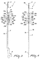
- the needle according to the invention generally designated by the reference numeral 1, comprises: a shank 2, which has an elongated shape, a head 3 and a latch 4.
- the head 3 is arranged at a longitudinal end or upper end of the shank 2 and is shaped like a hook that is open toward the front side of the shank 2, in a manner similar to known types of needles.
- the latch 4 is hinged to the shank 2 proximate to the head 3, about a pivoting axis 4a that is substantially perpendicular to the longitudinal axis of the shank 2, and rotatable about the pivoting axis 4a to open or close the head 3, as in known types of needles.
- the shank 2 has, along its extension, on its front side and proximate to its longitudinal end, or lower end, that lies opposite with respect to the head 3, at least one heel 5, which protrudes from its front side and can engage in a per se known manner the needle actuation cams provided in the knitting machine for hosiery or the like on which the needle 1 is to be fitted.
- the needle according to the invention comprises at least one lamina 6a, 6b, which is connected to the shank 2 and has, at each of the two opposite sides 7a, 7b of the shank 2, below the latch 4, a portion 8a, 8b, which is elastically flexible from an inactive position, in which it is close to the corresponding side 7a or 7b of the shank 2, as shown in Figures 3 and 4 , to an active position, in which it is spaced from the corresponding side 7a or 7b of the shank 2, as shown in Figures 1 and 2 .
- said portion 8a, 8b widens the loop of knitting 9 fitted on the shank 2 at said portion 8a, 8b of the lamina 6a, 6b and, in the space comprised between the portion 8a, 8b of the lamina 6a, 6b and the corresponding side 7a, 7b of the shank 2, when the portion 8a, 8b is in the active position, it is possible to insert the head 3 of an adjacent needle 1b to pick up the loop of knitting 9 by means of said adjacent needle 1b, as will become better apparent hereinafter.
- the shank 2 between the latch 4 and the end of the portion 8a, 8b of the lamina 6a, 6b that is directed toward the head 3, has a region 10 for blending the shank 2 with the portion 8a, 8b of the lamina 6a, 6b.
- the portions 8a, 8b can be part of a single lamina that is shaped conveniently so as to arrange the portion 8a on one side 7a of the shank 2 and the portion 8b on the opposite side 7b of the shank 2, preferably there are two laminas 6a, 6b, one for each side 7a, 7b of the shank 2, which are fixed, at their end directed toward the lower end of the shank 2, to the corresponding side 7a, 7b of the shank 2.
- the laminas 6a, 6b are extended toward the head 3 and rest, with their end directed toward the head 3, against the corresponding side 7a, 7b of the shank 2.
- Each of the laminas 6a, 6b has the respective portion 8a, 8b that can flex elastically toward or away from the corresponding side 7a, 7b of the shank 2.
- Each portion 8a, 8b can flex elastically toward the corresponding side 7a, 7b of the shank 2 in contrast with its elastic reaction, so as to move, in the absence of forces that act thereon, to the active position.
- Each lamina 6a, 6b is contoured so as to have: a lower region 20a, 20b, which lies so as to adhere to the corresponding side 7a, 7b of the shank 2 and is fixed thereto; an intermediate region, which constitutes the portion 8a, 8b; and an upper region 11a, 11b, which ends with the upper end 12a, 12b or which, as in the illustrated embodiment, is limited to said upper end 12a, 12b that rests against the corresponding side 7a, 7b of the shank 2.
- the intermediate region which constitutes the portion 8a, 8b that can flex elastically toward and away from the corresponding side 7a, 7b of the shank 2, is preferably constituted, starting from its lower end and in the absence of forces acting thereon: by a first segment 13a, 13b, which is folded away from the corresponding side 7a, 7b of the shank 2; by a second segment 14a, 14b, which is substantially parallel to the corresponding side 7a, 7b of the shank 2; and by a third segment 15a, 15b, which is folded toward the corresponding side 7a, 7b of the shank 2.
- Each portion 8a, 8b has, on its front side, a front protrusion 16a, 16b that defines, with its upper profile, a supporting shoulder 17a, 17b for the loop of knitting 9.
- each portion 8a, 8b has, on its rear side, a rear protrusion 18a, 18b that can engage by resting against the head 3 of an adjacent needle 1a, 1b.
- the lower region 20a, 20b of the lamina 6a, 6b is fixed to the side 7a, 7b at an appropriately provided recess and the portion 8a, 8b is shifted forward with respect to said lower region 20a, 20b.
- the blending region 10 is shaped like a wedge that tapers toward the head 3.
- the region of the needle 1 that is occupied by the portions 8a, 8b of the laminas 6a, 6b has, along the anteroposterior direction, an increased space occupation toward the front side of the needle with respect to the contiguous regions of the shank 2.
- the blending region 10 has a front face 10c, which is inclined with respect to the longitudinal axis of the shank 2 so as to blend said region occupied by the portions 8a, 8b of the laminas 6a, 6b with the portion of the shank 2 that is arranged above.
- Said front face 10c of the blending region 10 has a curved lower segment that blends it with its base side.
- the blending region 10 is delimited laterally by sides 10a, 10b that are shaped, at least for a segment starting from their upper end, like a plane that is inclined with respect to the longitudinal axis of the shank 2 and move mutually closer progressively toward the head 3.
- the lower end of the blending region 10 is wider than the distance between the two opposite sides 7a, 7b of the shank 2 in regions that are contiguous to the blending region 10.
- each lamina 6a, 6b i.e., the end that is directed toward the head 3, is connected to the blending region 10 proximate its base.
- each lamina 6a, 6b rests, so that it can slide parallel to the longitudinal axis of the shank 2, in a recess 19a, 19b formed in the corresponding side of the blending region 10.
- the blending region 10 can be formed at least partly by a block that is fixed to the shank 2, as in the embodiment shown in Figures 1 to 9 .
- the upper part of the blending region 10 is formed directly in the shank 2, while the remaining part of the blending region 10 is obtained, as a continuation of the upper part, in a block that is fixed rigidly to the shank 2.
- the blending region 10 can be obtained monolithically with the shank 2, as in the constructive variation of the needle according to the invention shown in Figure 10 .
- the upper ends 12a, 12b of the portions 8a, 8b of the laminas 6a, 6b are inserted slidingly within a slot 19 that is open at the front and in a downward region proximate to the base of the blending region 10.
- the first segment 13a, 13b of the portion 8a, 8b of the laminas 6a, 6b has a rear protrusion 22a, 22b, so as to allow said first portion 13a, 13b to engage in any case the sides 10a, 10b of the blending regions 10 of adjacent needles, provided like the needle 1, as a consequence of a longitudinal movement of the needle 1 with respect to the adjacent needles.
- the needle 1, arranged between the needles 1b, 1a is the needle that carries the loop of knitting 9 and must release it to the adjacent needle 1b, while the other needle 1a, arranged on the opposite side with respect to the needle 1b relative to the needle 1, is not affected by the transfer of the loop of knitting 9.
- the needle 1 is referenced hereinafter also as “releasing needle”
- the needle 1b is also referenced as “receiving needle”
- the needle 1a is also referenced as "inactive needle”.
- the needle 1 After forming the loop of knitting 9 and after knocking over the loop of knitting formed previously, is raised, by means of the needle actuation cams with which its heel 5 engages, so as to protrude for a segment above the knitting formation plane 21, which, as is known, is formed by the sinkers, not shown for the sake of simplicity, which retain the loops of knitting 9 that have just been formed.
- the extent of the lifting of the needle 1, which must release the loop of knitting 9, is such as to bring the portion 8a, 8b of the laminas 6a, 6b at the knitting formation plane 21 and extract the portion 8a, 8b completely from the region that is occupied by the so-called "strips" that delimit laterally the axial slots of the lateral surface of the needle cylinder in which the needles slide.
- the laminas 6a, 6b first pressed against the shank 2 of the releasing needle 1 by the presence of the strips, move away by elastic reaction from the shank 2 with their portion 8a, 8b, which thus passes into the active position.
- the shank 2 of the needle 1 slides within the loop of knitting 9 which, being crossed first by the blending region 10 and then by the portion 8a, 8b of the laminas 6a, 6b up to the resting shoulder 17a, 17b, is widened progressively in a manner in which it is suitable to be crossed at least by the receiving needle 1b.
- the presence of the blended region 10 ensures a gradual expansion of the loop of knitting 9, avoiding excessive stresses both of the loop and of the laminas 6a, 6b.
- the receiving needle 1b onto which the loop of knitting 9 is to be transferred, is moved upward with respect to the releasing needle 1, so as to insert its open head 3 in the space comprised between the portion 8a, 8b and the shank 2 of the releasing needle 1.
- the receiving needle 1b in this lifting, is arranged with its head 3 between the rear protrusion 18b and the side 7b of the shank 2 of the releasing needle 1. Thanks to this fact, the receiving needle 1b prevents the portion 8b of the lamina 6b from being crushed completely by the loop of knitting 9 against the side 7b of the shank 2 of the releasing needle 1 and the first segment 13b assuredly keeps open the latch of the receiving needle 1b.
- the inactive needle 1 a is in a lower position with respect to the position occupied by the receiving needle 1b, but its head 3 is in any case preferably arranged between the rear protrusion 18a and the side 7a of the shank 2 so as to not interfere with the process for transferring the loop of knitting 9.
- the releasing needle 1 is lowered and the receiving needle 1b is lifted, preferably to the position that corresponds to the held-stitch position.
- the descent of the releasing needle 1 moves the receiving needle 1b so that it protrudes with its head upward from the portion 8b of the lamina 6b. Moreover, the descent of the needle 1 causes the loop of knitting 9, arranged around the laminas 6a, 6b, to slide along the third segment 15b of the portion 8b, moving it toward the shank 2 and bringing it into the head of the receiving needle 1b.
- the two needles 1 and 1b can be lowered together below the knitting formation plane 21. During this lowering, the portions 8a, 8b of the laminas 6a, 6b, by engaging the strips, are moved into the inactive position.
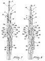
- the passage of the portions 8a, 8b of the laminas 6a, 6b from the active position to the inactive position after the transfer of the loop of knitting 9 can be achieved following the descent of the releasing needle 1 between the adjacent needles 1a, 1b, since the first segment 13a, 13b of the portions 8a, 8b of the laminas 6a, 6b engages the sides 10a, 10b of the blending region 10, as shown in Figures 7 and 8 .
- the inactive needle 1a which does not take part in the transfer of the loop of knitting 9, can be used to reduce the extent of the elastic deformation of the portion 8a of the lamina 6a of the adjacent releasing needle 1 away from the corresponding side 7a of the releasing needle 1, so as to reduce the stresses to which the loop of knitting 9 to be transferred and the other lamina 6b are subjected.
- the releasing needle 1 and the inactive needle 1a are lifted together, so that the releasing needle 1 slides within the loop of knitting 9 until it is moved against the resting shoulder 17b of the lamina 6b, whose portion 8b is in the active position, while the contact of the blending region 10 of the inactive needle 1a continues to limit the spacing of the portion 8a of the lamina 6a from the side 7a of the releasing needle 1.
- Figure 9 illustrates the sequence of actuation, in the direction indicated by the arrow 30, of set of three needles 1, 1a, 1b.
- the needles have all been shown with the corresponding latch 4 open, without altering the fact that the latch 4 is open or closed on the head 3 of the needles depending on the operating conditions of the needles.
- the needles according to the invention are used in a dial of a machine with cylinder and dial, the needles are moved radially outward instead of being raised and radially inward instead of being lowered.
- the particular structure of the needle according to the invention allows to provide said needle according to the invention with a reduced thickness, such as to allow its use in machines with high fineness (higher than 18 needles per inch).
- the needle according to the invention can be used advantageously also on double-bed machines to transfer a stitch from one bed to the other also with transfer from one needle of one bed to an adjacent needle of the same bed without requiring relative movements between the beds and therefore avoiding the problems of precision and complexity in execution that these movements entail.
- needles according to the invention with the possibility to transfer the stitches from either side of the needles on machines that can be actuated with a reciprocating motion allows to produce items of knitting with knitted regions of any shape with increasing or decreasing stitches, increasing their quality and degree of finish.
- the needle according to the invention fully achieves the intended aim, since it allows to perform direct transfer of a stitch from said needle to one of the two adjacent needles, i.e., in either direction, and the presence of the blending region achieves a gradual expansion of the loop of knitting to be transferred, avoiding excessive stresses both of the loop of knitting and of the elastically flexible laminas.
- said blending region can be used to actuate the transition from the active position to the inactive position and to limit or block the elastic deformation away from the corresponding side of the needle of the elastically flexible portions of the laminas of adjacent needles.
- the materials used, as well as the dimensions, may be any according to requirements and to the state of the art.
Landscapes
- Engineering & Computer Science (AREA)
- Textile Engineering (AREA)
- Knitting Machines (AREA)
Claims (12)
- Nadel zum Übertragen von Maschen von derselben auf angrenzende Nadeln für Strumpfstrickmaschinen oder dergleichen, umfassend einen Schaft (2), einen Kopf (3), der an einem Längsende bzw. oberen Ende des Schaftes (2) angeordnet und wie ein Haken konturiert ist, der zur Vorderseite des Schaftes (2) offen ist, und eine Zunge (4), die an dem Schaft (2) nahe dem Kopf (3) schwenkbar um eine Schwenkachse (4a) gelagert ist, die im Wesentlichen senkrecht zur Längsachse des Schaftes (2) ist, und die sich um die Schwenkachse (4a) drehen kann, um den Kopf (3) zu öffnen oder zu schließen, mindestens ein Blättchen (6a, 6b), das mit dem Schaft (2) verbunden ist und auf jeder der beiden entgegengesetzten Seiten (7a, 7b) des Schaftes (2) unterhalb der Zunge (4) einen Abschnitt (8a, 8b) hat, der sich elastisch von einer inaktiven Position, in der er näher zur entsprechenden Seite (7a, 7b) des Schaftes (2) ist, in eine aktive Position biegen kann, in der er zur entsprechenden Seite (7a, 7b) des Schaftes (2) beabstandet ist, wobei der elastisch biegsame Abschnitt (8a, 8b) des Blättchens (6a, 6b) in der aktiven Position eine Ausdehnung der Strickmasche (9) erzeugt, die an dem elastisch biegsamen Abschnitt (8a, 8b) des Blättchens (6a, 6b) auf den Schaft (2) aufgebracht ist, wobei der Knopf (3) einer angrenzenden Nadel (1b) in den Raum, der zwischen dem elastisch biegsamen Abschnitt (8a, 8b) des Blättchens (6a, 6b) in dessen aktiver Position und der entsprechenden Seite (7a, 7b) des Schaftes (2) vorhanden ist, eingeführt werden kann, um die Strickmasche (9) mittels der angrenzenden Nadel (1b) aufzunehmen, wobei der Schaft (2) zwischen der Zunge (4) und dem zum Kopf (3) gerichteten Ende des elastisch biegsamen Abschnittes (8a, 8b) des Blättchens (6a, 6b) einen Bereich (10) zum Verbinden des Schaftes (2) mit dem elastisch biegsamen Abschnitt (8a, 8b) des Blättchens (6a, 6b) hat, dadurch gekennzeichnet, dass der Verbindungsbereich (10) wie ein Keil geformt ist, der sich in Richtung des Kopfes (3) der Nadel (1) verjüngt.
- Nadel nach Anspruch 1, dadurch gekennzeichnet, dass das Blättchen (6a, 6b) für jede Seite des Schaftes (2) umfasst: einen unteren Bereich (20a), der so liegt, dass er an der entsprechenden Seite (7a, 7b) des Schaftes (2) anhaftet und daran befestigt ist, einen mittleren Bereich, der den elastisch biegsamen Abschnitt (8a, 8b) des Blättchens (6a, 6b) bildet, und einen oberen Bereich (11a, 11b), der mit dem oberen Ende (12a, 12b) des Blättchens endet, das an der entsprechenden Seite (7a, 7b) des Schaftes (2) anliegt.
- Nadel nach einem oder mehr der vorhergehenden Ansprüche, dadurch gekennzeichnet, dass der untere Bereich (20a, 20b) des Blättchens (6a, 6b) an der entsprechenden Seite (7a, 7b) des Schaftes (2) an einer entsprechenden Aussparung befestigt ist und der elastisch biegsame Abschnitt (8a, 8b) des Blättchens (6a, 6b) in Bezug auf den unteren Bereich (20a, 20b) des Blättchens (6a, 6b) nach vorne verschoben ist.
- Nadel nach einem oder mehr der vorhergehenden Ansprüche, dadurch gekennzeichnet, dass der Bereich der Nadel (1), an dem die elastisch biegsamen Abschnitte (8a, 8b) des Blättchens (6a, 6b) angeordnet sind, entlang der anteroposterioren Richtung der Nadel (1) eine Raumeinnahme hat, die in Richtung der Vorderseite der Nadel (1) in Bezug auf die angrenzenden Bereiche zunimmt, wobei der Verbindungsbereich (10) eine Vorderfläche (10c) hat, die in Bezug auf die Längsachse des Schaftes (2) geneigt ist, um an der Vorderseite den Bereich des Schaftes (2), der mit den elastisch biegsamen Abschnitten (8a, 8b) des Blättchens (6a, 6b) versehen ist, mit dem darüber liegenden angrenzenden Bereich zu verbinden.
- Nadel nach einem oder mehr der vorhergehenden Ansprüche, dadurch gekennzeichnet, dass der Verbindungsbereich (10) seitlich von Seitenflächen (10a, 10b) begrenzt ist, die zumindest für einen Abschnitt, der von ihren oberen Enden ausgeht, wie eine Ebene geformt sind, die in Bezug auf die Längsachse des Schaftes (2) geneigt ist, und die sich fortschreitend in Richtung des Kopfes (3) einander annähern.
- Nadel nach einem oder mehr der vorhergehenden Ansprüche, dadurch gekennzeichnet, dass das untere Ende des Verbindungsbereiches (10) breiter als der Abstand zwischen den zwei entgegengesetzten Seiten (7a, 7b) des Schaftes (2) in Bereichen ist, die an den Verbindungsbereich (10) angrenzen.
- Nadel nach einem oder mehr der vorhergehenden Ansprüche, dadurch gekennzeichnet, dass das zum Kopf (3) gerichtete obere Ende (12a, 12b) der elastisch biegsamen Abschnitte (8a, 8b) des Blättchens (6a, 6b) mit dem Verbindungsbereich (10) nahe dessen Basis verbunden ist.
- Nadel nach einem oder mehr der vorhergehenden Ansprüche, dadurch gekennzeichnet, dass das zum Kopf (3) gerichtete obere Ende (12a, 12b) jedes der elastisch biegsamen Abschnitte (8a, 8b) des Blättchens (6a, 6b) in einer Aussparung (19a, 19b) ruht, so dass es entlang einer zur Längsachse des Schaftes (2) parallelen Richtung gleiten kann, wobei die Aussparung in der entsprechenden Seite (10a, 10b) des Verbindungsbereiches (10) ausgebildet ist.
- Nadel nach einem oder mehr der vorhergehenden Ansprüche, dadurch gekennzeichnet, dass die Vorderfläche (10c) des Verbindungsbereichs (10) einen gebogenen Verbindungsabschnitt hat, der nahe der Basis des Verbindungsbereichs (10) ist.
- Nadel nach einem oder mehr der vorhergehenden Ansprüche, dadurch gekennzeichnet, dass der Verbindungsbereich (10) zumindest teilweise monolithisch mit dem Schaft (2) vorgesehen ist.
- Nadel nach einem oder mehr der vorhergehenden Ansprüche, dadurch gekennzeichnet, dass der Verbindungsbereich (10) zumindest teilweise aus einem Block gebildet ist, der an dem Schaft (2) befestigt ist.
- Nadel nach einem oder mehr der vorhergehenden Ansprüche, dadurch gekennzeichnet, dass jeder der elastisch biegsamen Abschnitte (8a, 8b) des Blättchens (6a, 6b), ausgehend von seinem unteren Ende und wenn keine Kräfte darauf ausgeübt werden, gebildet ist: von einem ersten Abschnitt (13a, 13b), der von der entsprechenden Seite (7a, 7b) des Schaftes (2) weggebogen ist, von einem zweiten Abschnitt (14a, 14b), der im Wesentlichen parallel zur entsprechenden Seite (7a, 7b) des Schaftes (2) ist, und von einem dritten Abschnitt (15a, 15b), der zur entsprechenden Seite (7a, 7b) des Schaftes (2) gebogen ist, wobei der erste Abschnitt (13a, 13b) zum Zwecke des Übergangs des elastisch biegsamen Abschnittes (8a, 8b) des Blättchens (6a, 6b) von der aktiven Position in die inaktive Position als Folge der Längsbewegung der Nadel (1) in Bezug auf die angrenzende Nadel (1b) gleitend mit einer Seitenfläche (10a, 10b) des Verbindungsbereichs (10) einer angrenzenden Nadel (1b) in Eingriff kommen kann.
Applications Claiming Priority (2)
| Application Number | Priority Date | Filing Date | Title |
|---|---|---|---|
| IT000122A ITMI20080122A1 (it) | 2008-01-28 | 2008-01-28 | Ago per operare il trasferimento di punti di maglia dallo stesso ago ad aghi adiacenti per macchine per maglieria, calzetteria o simili. |
| PCT/EP2009/050805 WO2009095360A1 (en) | 2008-01-28 | 2009-01-23 | Needle for transferring stitches from the needle itself to adjacent needles for hosiery knitting machines or the like |
Publications (3)
| Publication Number | Publication Date |
|---|---|
| EP2240635A1 EP2240635A1 (de) | 2010-10-20 |
| EP2240635B1 EP2240635B1 (de) | 2011-09-21 |
| EP2240635B9 true EP2240635B9 (de) | 2012-09-19 |
Family
ID=40290137
Family Applications (1)
| Application Number | Title | Priority Date | Filing Date |
|---|---|---|---|
| EP09706216A Not-in-force EP2240635B9 (de) | 2008-01-28 | 2009-01-23 | Nadel zur übertragung von maschen von der nadel selbst auf benachbarte nadeln für strumpfstrickmaschinen oder ähnlichem |
Country Status (6)
| Country | Link |
|---|---|
| EP (1) | EP2240635B9 (de) |
| KR (1) | KR20100107040A (de) |
| CN (1) | CN101939474B (de) |
| AT (1) | ATE525507T1 (de) |
| IT (1) | ITMI20080122A1 (de) |
| WO (1) | WO2009095360A1 (de) |
Families Citing this family (2)
| Publication number | Priority date | Publication date | Assignee | Title |
|---|---|---|---|---|
| KR20120045475A (ko) | 2010-10-29 | 2012-05-09 | 엘지디스플레이 주식회사 | 유기전계발광소자 및 그 제조방법 |
| DE102017114412A1 (de) * | 2017-06-28 | 2019-01-17 | Terrot Gmbh | Maschenbildungselemente für eine Strickmaschine, Strickmaschine und Strickverfahren |
Family Cites Families (3)
| Publication number | Priority date | Publication date | Assignee | Title |
|---|---|---|---|---|
| GB495379A (en) * | 1936-05-09 | 1938-11-08 | Jacquard Knitting Machine Co Inc | Improvements in or relating to knitting machines |
| DE10227533C1 (de) * | 2002-06-20 | 2003-12-11 | Groz Beckert Kg | Nadel mit Umhängefeder |
| ATE462814T1 (de) * | 2005-11-18 | 2010-04-15 | Santoni & C Spa | Nadel zur übergabe von maschen an benachbarte nadeln für strick- oder wirkmaschinen oder dergleichen |
-
2008
- 2008-01-28 IT IT000122A patent/ITMI20080122A1/it unknown
-
2009
- 2009-01-23 WO PCT/EP2009/050805 patent/WO2009095360A1/en not_active Ceased
- 2009-01-23 CN CN2009801038056A patent/CN101939474B/zh not_active Expired - Fee Related
- 2009-01-23 EP EP09706216A patent/EP2240635B9/de not_active Not-in-force
- 2009-01-23 KR KR1020107017458A patent/KR20100107040A/ko not_active Ceased
- 2009-01-23 AT AT09706216T patent/ATE525507T1/de not_active IP Right Cessation
Also Published As
| Publication number | Publication date |
|---|---|
| EP2240635A1 (de) | 2010-10-20 |
| WO2009095360A1 (en) | 2009-08-06 |
| CN101939474A (zh) | 2011-01-05 |
| ITMI20080122A1 (it) | 2009-07-29 |
| ATE525507T1 (de) | 2011-10-15 |
| KR20100107040A (ko) | 2010-10-04 |
| EP2240635B1 (de) | 2011-09-21 |
| CN101939474B (zh) | 2012-02-15 |
Similar Documents
| Publication | Publication Date | Title |
|---|---|---|
| EP2148949B1 (de) | Betriebssichere maschenbildende maschine mit zungennadeln und keinen platinen | |
| EP3165651B1 (de) | Flachstrickmaschine | |
| EP2240635B1 (de) | Nadel zur übertragung von maschen von der nadel selbst auf benachbarte nadeln für strumpfstrickmaschinen oder ähnlichem | |
| EP2240634B1 (de) | Nadel zur maschenübertragung von der nadel selbst auf benachbarte nadeln für wirkmaschinen oder dergleichen | |
| EP2002043B1 (de) | Zweizylindrige rundstrickmaschine für miederwaren und andere strickwaren | |
| EP2240636B1 (de) | Nadel zur übertragung von maschen von der nadel selbst auf benachbarte nadeln in strumpfstrickmaschinen oder ähnlichem | |
| EP1948859B1 (de) | Nadel zur übergabe von maschen an benachbarte nadeln für strick- oder wirkmaschinen oder dergleichen | |
| JP2013139644A (ja) | 横編機のシンカー装置 | |
| EP3165652B1 (de) | Strickverfahren und rundstrickmaschine | |
| CN101605935A (zh) | 织针运动机构 | |
| CN101415870B (zh) | 用于袜类或类似物的圆型针织机 | |
| EP2681353A1 (de) | Verbesserte platine für rundstrickmaschinen zur herstellung von strumpfwaren mit hohem widerstand gegen beschädigungsgefahr durch benachbarte nadeln | |
| HK1120575B (en) | Needle for transferring stitches therefrom to adjacent needles for hosiery knitting machines or the like | |
| JP5232862B2 (ja) | 円形靴下編み機における編み目の移動のためのプッシャー | |
| CZ300949B6 (cs) | Zarízení okrouhlého pletacího stroje pro výrobu ponožkového zboží |
Legal Events
| Date | Code | Title | Description |
|---|---|---|---|
| PUAI | Public reference made under article 153(3) epc to a published international application that has entered the european phase |
Free format text: ORIGINAL CODE: 0009012 |
|
| 17P | Request for examination filed |
Effective date: 20100727 |
|
| AK | Designated contracting states |
Kind code of ref document: A1 Designated state(s): AT BE BG CH CY CZ DE DK EE ES FI FR GB GR HR HU IE IS IT LI LT LU LV MC MK MT NL NO PL PT RO SE SI SK TR |
|
| AX | Request for extension of the european patent |
Extension state: AL BA RS |
|
| GRAP | Despatch of communication of intention to grant a patent |
Free format text: ORIGINAL CODE: EPIDOSNIGR1 |
|
| DAX | Request for extension of the european patent (deleted) | ||
| RTI1 | Title (correction) |
Free format text: NEEDLE FOR TRANSFERRING STITCHES FROM THE NEEDLE ITSELF TO ADJACENT NEEDLES FOR HOSIERY KNITTING MACHINES OR THE LIKE |
|
| GRAS | Grant fee paid |
Free format text: ORIGINAL CODE: EPIDOSNIGR3 |
|
| GRAA | (expected) grant |
Free format text: ORIGINAL CODE: 0009210 |
|
| AK | Designated contracting states |
Kind code of ref document: B1 Designated state(s): AT BE BG CH CY CZ DE DK EE ES FI FR GB GR HR HU IE IS IT LI LT LU LV MC MK MT NL NO PL PT RO SE SI SK TR |
|
| REG | Reference to a national code |
Ref country code: GB Ref legal event code: FG4D |
|
| REG | Reference to a national code |
Ref country code: CH Ref legal event code: EP |
|
| REG | Reference to a national code |
Ref country code: IE Ref legal event code: FG4D |
|
| REG | Reference to a national code |
Ref country code: DE Ref legal event code: R096 Ref document number: 602009002703 Country of ref document: DE Effective date: 20111117 |
|
| REG | Reference to a national code |
Ref country code: NL Ref legal event code: VDEP Effective date: 20110921 |
|
| PG25 | Lapsed in a contracting state [announced via postgrant information from national office to epo] |
Ref country code: LT Free format text: LAPSE BECAUSE OF FAILURE TO SUBMIT A TRANSLATION OF THE DESCRIPTION OR TO PAY THE FEE WITHIN THE PRESCRIBED TIME-LIMIT Effective date: 20110921 Ref country code: SE Free format text: LAPSE BECAUSE OF FAILURE TO SUBMIT A TRANSLATION OF THE DESCRIPTION OR TO PAY THE FEE WITHIN THE PRESCRIBED TIME-LIMIT Effective date: 20110921 Ref country code: NO Free format text: LAPSE BECAUSE OF FAILURE TO SUBMIT A TRANSLATION OF THE DESCRIPTION OR TO PAY THE FEE WITHIN THE PRESCRIBED TIME-LIMIT Effective date: 20111221 Ref country code: FI Free format text: LAPSE BECAUSE OF FAILURE TO SUBMIT A TRANSLATION OF THE DESCRIPTION OR TO PAY THE FEE WITHIN THE PRESCRIBED TIME-LIMIT Effective date: 20110921 Ref country code: HR Free format text: LAPSE BECAUSE OF FAILURE TO SUBMIT A TRANSLATION OF THE DESCRIPTION OR TO PAY THE FEE WITHIN THE PRESCRIBED TIME-LIMIT Effective date: 20110921 |
|
| LTIE | Lt: invalidation of european patent or patent extension |
Effective date: 20110921 |
|
| PG25 | Lapsed in a contracting state [announced via postgrant information from national office to epo] |
Ref country code: LV Free format text: LAPSE BECAUSE OF FAILURE TO SUBMIT A TRANSLATION OF THE DESCRIPTION OR TO PAY THE FEE WITHIN THE PRESCRIBED TIME-LIMIT Effective date: 20110921 Ref country code: AT Free format text: LAPSE BECAUSE OF FAILURE TO SUBMIT A TRANSLATION OF THE DESCRIPTION OR TO PAY THE FEE WITHIN THE PRESCRIBED TIME-LIMIT Effective date: 20110921 Ref country code: GR Free format text: LAPSE BECAUSE OF FAILURE TO SUBMIT A TRANSLATION OF THE DESCRIPTION OR TO PAY THE FEE WITHIN THE PRESCRIBED TIME-LIMIT Effective date: 20111222 Ref country code: SI Free format text: LAPSE BECAUSE OF FAILURE TO SUBMIT A TRANSLATION OF THE DESCRIPTION OR TO PAY THE FEE WITHIN THE PRESCRIBED TIME-LIMIT Effective date: 20110921 Ref country code: CY Free format text: LAPSE BECAUSE OF FAILURE TO SUBMIT A TRANSLATION OF THE DESCRIPTION OR TO PAY THE FEE WITHIN THE PRESCRIBED TIME-LIMIT Effective date: 20110921 |
|
| REG | Reference to a national code |
Ref country code: AT Ref legal event code: MK05 Ref document number: 525507 Country of ref document: AT Kind code of ref document: T Effective date: 20110921 |
|
| PG25 | Lapsed in a contracting state [announced via postgrant information from national office to epo] |
Ref country code: BE Free format text: LAPSE BECAUSE OF FAILURE TO SUBMIT A TRANSLATION OF THE DESCRIPTION OR TO PAY THE FEE WITHIN THE PRESCRIBED TIME-LIMIT Effective date: 20110921 |
|
| PG25 | Lapsed in a contracting state [announced via postgrant information from national office to epo] |
Ref country code: CZ Free format text: LAPSE BECAUSE OF FAILURE TO SUBMIT A TRANSLATION OF THE DESCRIPTION OR TO PAY THE FEE WITHIN THE PRESCRIBED TIME-LIMIT Effective date: 20110921 Ref country code: IS Free format text: LAPSE BECAUSE OF FAILURE TO SUBMIT A TRANSLATION OF THE DESCRIPTION OR TO PAY THE FEE WITHIN THE PRESCRIBED TIME-LIMIT Effective date: 20120121 Ref country code: SK Free format text: LAPSE BECAUSE OF FAILURE TO SUBMIT A TRANSLATION OF THE DESCRIPTION OR TO PAY THE FEE WITHIN THE PRESCRIBED TIME-LIMIT Effective date: 20110921 |
|
| PG25 | Lapsed in a contracting state [announced via postgrant information from national office to epo] |
Ref country code: NL Free format text: LAPSE BECAUSE OF FAILURE TO SUBMIT A TRANSLATION OF THE DESCRIPTION OR TO PAY THE FEE WITHIN THE PRESCRIBED TIME-LIMIT Effective date: 20110921 Ref country code: PL Free format text: LAPSE BECAUSE OF FAILURE TO SUBMIT A TRANSLATION OF THE DESCRIPTION OR TO PAY THE FEE WITHIN THE PRESCRIBED TIME-LIMIT Effective date: 20110921 Ref country code: EE Free format text: LAPSE BECAUSE OF FAILURE TO SUBMIT A TRANSLATION OF THE DESCRIPTION OR TO PAY THE FEE WITHIN THE PRESCRIBED TIME-LIMIT Effective date: 20110921 Ref country code: RO Free format text: LAPSE BECAUSE OF FAILURE TO SUBMIT A TRANSLATION OF THE DESCRIPTION OR TO PAY THE FEE WITHIN THE PRESCRIBED TIME-LIMIT Effective date: 20110921 Ref country code: PT Free format text: LAPSE BECAUSE OF FAILURE TO SUBMIT A TRANSLATION OF THE DESCRIPTION OR TO PAY THE FEE WITHIN THE PRESCRIBED TIME-LIMIT Effective date: 20120123 |
|
| PLBE | No opposition filed within time limit |
Free format text: ORIGINAL CODE: 0009261 |
|
| STAA | Information on the status of an ep patent application or granted ep patent |
Free format text: STATUS: NO OPPOSITION FILED WITHIN TIME LIMIT |
|
| PG25 | Lapsed in a contracting state [announced via postgrant information from national office to epo] |
Ref country code: DK Free format text: LAPSE BECAUSE OF FAILURE TO SUBMIT A TRANSLATION OF THE DESCRIPTION OR TO PAY THE FEE WITHIN THE PRESCRIBED TIME-LIMIT Effective date: 20110921 |
|
| 26N | No opposition filed |
Effective date: 20120622 |
|
| PG25 | Lapsed in a contracting state [announced via postgrant information from national office to epo] |
Ref country code: MC Free format text: LAPSE BECAUSE OF NON-PAYMENT OF DUE FEES Effective date: 20120131 |
|
| REG | Reference to a national code |
Ref country code: DE Ref legal event code: R097 Ref document number: 602009002703 Country of ref document: DE Effective date: 20120622 |
|
| REG | Reference to a national code |
Ref country code: FR Ref legal event code: ST Effective date: 20120928 |
|
| REG | Reference to a national code |
Ref country code: IE Ref legal event code: MM4A |
|
| PG25 | Lapsed in a contracting state [announced via postgrant information from national office to epo] |
Ref country code: FR Free format text: LAPSE BECAUSE OF NON-PAYMENT OF DUE FEES Effective date: 20120131 |
|
| PG25 | Lapsed in a contracting state [announced via postgrant information from national office to epo] |
Ref country code: IE Free format text: LAPSE BECAUSE OF NON-PAYMENT OF DUE FEES Effective date: 20120123 |
|
| PG25 | Lapsed in a contracting state [announced via postgrant information from national office to epo] |
Ref country code: MK Free format text: LAPSE BECAUSE OF FAILURE TO SUBMIT A TRANSLATION OF THE DESCRIPTION OR TO PAY THE FEE WITHIN THE PRESCRIBED TIME-LIMIT Effective date: 20110921 |
|
| PG25 | Lapsed in a contracting state [announced via postgrant information from national office to epo] |
Ref country code: ES Free format text: LAPSE BECAUSE OF FAILURE TO SUBMIT A TRANSLATION OF THE DESCRIPTION OR TO PAY THE FEE WITHIN THE PRESCRIBED TIME-LIMIT Effective date: 20120101 |
|
| PG25 | Lapsed in a contracting state [announced via postgrant information from national office to epo] |
Ref country code: BG Free format text: LAPSE BECAUSE OF FAILURE TO SUBMIT A TRANSLATION OF THE DESCRIPTION OR TO PAY THE FEE WITHIN THE PRESCRIBED TIME-LIMIT Effective date: 20111221 |
|
| PG25 | Lapsed in a contracting state [announced via postgrant information from national office to epo] |
Ref country code: MT Free format text: LAPSE BECAUSE OF FAILURE TO SUBMIT A TRANSLATION OF THE DESCRIPTION OR TO PAY THE FEE WITHIN THE PRESCRIBED TIME-LIMIT Effective date: 20110921 |
|
| REG | Reference to a national code |
Ref country code: CH Ref legal event code: PL |
|
| GBPC | Gb: european patent ceased through non-payment of renewal fee |
Effective date: 20130123 |
|
| PG25 | Lapsed in a contracting state [announced via postgrant information from national office to epo] |
Ref country code: LI Free format text: LAPSE BECAUSE OF NON-PAYMENT OF DUE FEES Effective date: 20130131 Ref country code: CH Free format text: LAPSE BECAUSE OF NON-PAYMENT OF DUE FEES Effective date: 20130131 |
|
| PG25 | Lapsed in a contracting state [announced via postgrant information from national office to epo] |
Ref country code: GB Free format text: LAPSE BECAUSE OF NON-PAYMENT OF DUE FEES Effective date: 20130123 |
|
| PG25 | Lapsed in a contracting state [announced via postgrant information from national office to epo] |
Ref country code: TR Free format text: LAPSE BECAUSE OF FAILURE TO SUBMIT A TRANSLATION OF THE DESCRIPTION OR TO PAY THE FEE WITHIN THE PRESCRIBED TIME-LIMIT Effective date: 20110921 |
|
| PG25 | Lapsed in a contracting state [announced via postgrant information from national office to epo] |
Ref country code: LU Free format text: LAPSE BECAUSE OF NON-PAYMENT OF DUE FEES Effective date: 20120123 |
|
| PG25 | Lapsed in a contracting state [announced via postgrant information from national office to epo] |
Ref country code: HU Free format text: LAPSE BECAUSE OF FAILURE TO SUBMIT A TRANSLATION OF THE DESCRIPTION OR TO PAY THE FEE WITHIN THE PRESCRIBED TIME-LIMIT Effective date: 20090123 |
|
| REG | Reference to a national code |
Ref country code: DE Ref legal event code: R082 Ref document number: 602009002703 Country of ref document: DE Representative=s name: SCHAUMBURG & PARTNER PATENTANWAELTE GBR, DE Ref country code: DE Ref legal event code: R082 Ref document number: 602009002703 Country of ref document: DE Representative=s name: SCHAUMBURG & PARTNER PATENTANWAELTE MBB, DE Ref country code: DE Ref legal event code: R082 Ref document number: 602009002703 Country of ref document: DE Representative=s name: SCHAUMBURG UND PARTNER PATENTANWAELTE MBB, DE |
|
| PGFP | Annual fee paid to national office [announced via postgrant information from national office to epo] |
Ref country code: IT Payment date: 20191023 Year of fee payment: 12 |
|
| PG25 | Lapsed in a contracting state [announced via postgrant information from national office to epo] |
Ref country code: IT Free format text: LAPSE BECAUSE OF NON-PAYMENT OF DUE FEES Effective date: 20210123 |
|
| PGFP | Annual fee paid to national office [announced via postgrant information from national office to epo] |
Ref country code: DE Payment date: 20230106 Year of fee payment: 15 |
|
| P01 | Opt-out of the competence of the unified patent court (upc) registered |
Effective date: 20230528 |
|
| REG | Reference to a national code |
Ref country code: DE Ref legal event code: R119 Ref document number: 602009002703 Country of ref document: DE |
|
| PG25 | Lapsed in a contracting state [announced via postgrant information from national office to epo] |
Ref country code: DE Free format text: LAPSE BECAUSE OF NON-PAYMENT OF DUE FEES Effective date: 20240801 |
|
| PG25 | Lapsed in a contracting state [announced via postgrant information from national office to epo] |
Ref country code: DE Free format text: LAPSE BECAUSE OF NON-PAYMENT OF DUE FEES Effective date: 20240801 |