EP2240634B1 - Nadel zur maschenübertragung von der nadel selbst auf benachbarte nadeln für wirkmaschinen oder dergleichen - Google Patents
Nadel zur maschenübertragung von der nadel selbst auf benachbarte nadeln für wirkmaschinen oder dergleichen Download PDFInfo
- Publication number
- EP2240634B1 EP2240634B1 EP09706885.2A EP09706885A EP2240634B1 EP 2240634 B1 EP2240634 B1 EP 2240634B1 EP 09706885 A EP09706885 A EP 09706885A EP 2240634 B1 EP2240634 B1 EP 2240634B1
- Authority
- EP
- European Patent Office
- Prior art keywords
- needle
- lamina
- shank
- elastically flexible
- flexible portion
- Prior art date
- Legal status (The legal status is an assumption and is not a legal conclusion. Google has not performed a legal analysis and makes no representation as to the accuracy of the status listed.)
- Active
Links
Images


Classifications
-
- D—TEXTILES; PAPER
- D04—BRAIDING; LACE-MAKING; KNITTING; TRIMMINGS; NON-WOVEN FABRICS
- D04B—KNITTING
- D04B35/00—Details of, or auxiliary devices incorporated in, knitting machines, not otherwise provided for
- D04B35/02—Knitting tools or instruments not provided for in group D04B15/00 or D04B27/00
- D04B35/04—Latch needles
-
- D—TEXTILES; PAPER
- D04—BRAIDING; LACE-MAKING; KNITTING; TRIMMINGS; NON-WOVEN FABRICS
- D04B—KNITTING
- D04B15/00—Details of, or auxiliary devices incorporated in, weft knitting machines, restricted to machines of this kind
- D04B15/14—Needle cylinders
-
- D—TEXTILES; PAPER
- D04—BRAIDING; LACE-MAKING; KNITTING; TRIMMINGS; NON-WOVEN FABRICS
- D04B—KNITTING
- D04B9/00—Circular knitting machines with independently-movable needles
- D04B9/20—Circular knitting machines with independently-movable needles with provision for narrowing or widening; with reciprocatory action, e.g. for knitting of flat portions
Definitions
- the present invention relates to a needle for transferring stitches from the needle itself to adjacent needles for knitting machines for hosiery or the like.
- needles In the field of knitting machines for hosiery, needles are known which are provided in order to allow to transfer a stitch or loop of knitting from one needle to an adjacent needle arranged in the same bed.
- a needle of this kind allows to transfer the stitch exclusively onto the needle that is arranged on one side of the needle that has to release the stitch.
- WO2007/057041 by the same Applicant, assumed included herein as reference, illustrates a needle that is capable of transferring, according to the requirements, the stitch onto the needle that is arranged on one side or to the needle that is arranged on the opposite side of the needle that has to release the stitch.
- the needle according to WO2007/057041 comprises: a shank, a head arranged at a longitudinal or upper end of the shank, and a latch that is hinged to the shank proximate to the head, about a pivoting axis that is substantially perpendicular to the longitudinal axis of the shank and rotatable about said pivoting axis in order to open or close the head.
- the needle comprises at least one elastically flexible lamina, which is associated with the shank and defines, on the two opposite sides of the shank, below the latch, two receptacles, one for each side of the shank. It is possible to insert in each of these receptacles the head of an adjacent needle in order to transfer the loop of knitting, carried by the shank and arranged at the receptacles, from said needle to the adjacent needle.
- This needle during testing, has proved to be susceptible of improvements aimed mainly at reducing the wear of the lamina and of the head and at achieving higher reliability in transferring the stitch or loop of knitting.
- the aim of the present invention is indeed to provide a needle for transferring stitches from said needle to adjacent needles for knitting machines for hosiery or the like that ensures high durability.
- an object of the invention is to provide a needle that allows to achieve high reliability in transferring the stitch or loop of knitting.
- Another object of the invention is to provide a needle that reduces the stresses on the stitch or loop of knitting and on the portions of the needle that transfer the stitch or loop of knitting.
- Still another object of the invention is to provide a needle that is highly versatile in use.
- Another object of the invention is to provide a needle that can have a reduced thickness, so as to allow its use on high-fineness machines, particularly in machines with more than 12 needles per inch.
- a needle for transferring stitches from said needle to adjacent needles for knitting machines for hosiery or the like comprising a shank, a head that is arranged at a longitudinal or upper end of said shank and is contoured like a hook that is open toward the front side of said shank, and a latch, which is pivoted to said shank proximate to said head, about a pivoting axis that is substantially perpendicular to the longitudinal axis of said shank, and rotatable about said pivoting axis in order to open or close said head, characterized in that it comprises at least one lamina that is connected to said shank and has, on each of the two opposite sides of said shank, below said latch, a portion that can flex elastically from an inactive position, in which it is closer to the corresponding side of the shank, to an active position, in which it is spaced from the corresponding side of the shank; in said active position
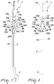
- the needle according to the invention generally designated by the reference numeral 1 both in the embodiment shown in Figures 1 to 12 and in the constructive variations shown in the subsequent figures, comprises: a shank 2, which has an elongated shape, a head 3 and a latch 4.
- the head 3 is arranged at a longitudinal end or upper end of the shank 2 and is shaped like a hook that is open toward the front side of the shank 2, in a manner similar to known types of needle.
- the latch 4 is hinged to the shank 2 proximate to the head 3, about a pivoting axis 4a that is substantially perpendicular to the longitudinal axis of the shank 2, and rotatable about the pivoting axis 4a to open or close the head 3, as in known types of needle.
- the shank 2 has, along its extension, on its front side and proximate to its longitudinal end, or lower end, that lies opposite with respect to the head 3, at least one heel 5, which protrudes from its front side and can engage in a per se known manner the needle actuation cams provided in the knitting machine for hosiery or the like on which the needle 1 is to be fitted.
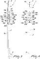
- the needle according to the invention in the embodiment shown in Figures 1 to 12 , comprises at least one lamina 6a, 6b, which is connected to the shank 2 and has, on each of the two opposite sides 7a, 7b of the shank 2, below the latch 4, a portion 8a, 8b, which is elastically flexible from an inactive position, in which it is close to the corresponding side 7a or 7b of the shank 2, as shown in particular in Figures 3 and 4 , to an active position, in which it is spaced from the corresponding side 7a or 7b of the shank 2, as shown in particular in Figures 1 and 2 .
- said portion 8a, 8b widens the loop of knitting 9 fitted on the shank 2 at said portion 8a, 8b of the lamina 6a, 6b and, in the space comprised between the portion 8a, 8b of the lamina 6a, 6b and the corresponding side 7a, 7b of the shank 2, when the portion 8a, 8b is in the active position, it is possible to insert the head 3 of an adjacent needle 1b to pick up the loop of knitting 9 by means of said adjacent needle 1b, as will become better apparent hereinafter.
- the lamina 6a, 6b rests, at least with its end directed toward the head 3, against the shank 2 in a region located forward with respect to the head 3. Substantially, the region of said end, which constitutes the upper end of the lamina 6a, 6b, that rests against the shank 2 is shifted forward with respect to the position of the head 3.
- the portion 8a, 8b of the lamina 6a, 6b has a region that can be superimposed laterally, on the opposite side with respect to the corresponding side 7a, 7b of the shank 2, on the head of an adjacent needle 1a, 1b inserted in the space comprised between the portion 8a, 8b of the lamina 6a, 6b, in the active position, and the corresponding side 7a, 7b of the shank 2.
- the portions 8a, 8b can be part of a single lamina that is shaped conveniently so as to arrange the portion 8a on one side 7a of the shank 2 and the portion 8b on the opposite side 7b of the shank 2, as will be described in greater detail hereinafter, preferably there are two laminas 6a, 6b, one for each side 7a, 7b of the shank 2, which are fixed, at their end directed toward the lower end of the shank 2, to the corresponding side 7a, 7b of the shank 2.
- the laminas 6a, 6b are extended toward the head 3 and rest, with their end directed toward the head 3, against the corresponding side 7a, 7b of the shank 2.
- Each of the laminas 6a, 6b has the respective portion 8a, 8b that can flex elastically toward or away from the corresponding side 7a, 7b of the shank 2.
- Each portion 8a, 8b can flex elastically toward the corresponding side 7a, 7b of the shank 2 in contrast with its elastic reaction, so as to move, in the absence of forces that act thereon, to the active position.
- Each lamina 6a, 6b is contoured so as to have: a lower region 20a, 20b, which lies so as to adhere to the corresponding side 7a, 7b of the shank 2 and is fixed thereto; an intermediate region, which constitutes the portion 8a, 8b; and an upper region 11a, 11b, which ends with the upper end 12a, 12b or which, as in the illustrated embodiment, is limited to said upper end 12a, 12b that rests against the corresponding side 7a, 7b of the shank 2.
- the intermediate region which constitutes the portion 8a, 8b that can flex elastically toward and away from the corresponding side 7a, 7b of the shank 2, is preferably constituted, starting from its lower end and in the absence of forces acting thereon: by a first segment 13a, 13b, which is folded away from the corresponding side 7a, 7b of the shank 2; by a second segment 14a, 14b, which is substantially parallel to the corresponding side 7a, 7b of the shank 2; and by a third segment 15a, 15b, which is folded toward the corresponding side 7a, 7b of the shank 2.
- Each portion 8a, 8b has, on its front side, a front protrusion 16a, 16b that defines, with its upper profile, a supporting shoulder 17a, 17b for the loop of knitting 9.
- the supporting shoulder 17a, 17b is defined on the upper side of a front protrusion 16a, 16b of the second segment 14a, 14b of the portion 8a, 8b of the lamina 6a, 6b.
- each portion 8a, 8b has, on its rear side, a rear protrusion 18a, 18b that constitutes the region that can be superimposed laterally, on the opposite side with respect to the corresponding side 7a, 7b of the shank 2, on the head 3 of an adjacent needle 1a, 1b.
- Said rear protrusion 18a, 18b can engage by resting against the head 3 of the adjacent needle 1a, 1b.
- the rear protrusion 18a, 18b is provided on the rear side of the second segment 14a, 14b of the portion 8a, 8b of the lamina 6a, 6b.
- the first segment 13a, 13b of the portion 8a, 8b of the lamina 6a, 6b, at least proximate to the second segment 14a, 14b of the portion 8a, 8b of the lamina 6a, 6b, is located forward with respect to the head 3, so as to define an abutment for the latch of an adjacent needle during the transfer of the loop of knitting 9, as will become better apparent hereinafter.
- the lower region 20a, 20b of the lamina 6a, 6b is fixed to the side 7a, 7b at an appropriately provided recess and the portion 8a, 8b is shifted forward with respect to said lower region 20a, 20b.
- the region of the needle 1 that is occupied by the portions 8a, 8b of the laminas 6a, 6b has, along the anteroposterior direction, an increased space occupation toward the front side of the needle with respect to the contiguous regions of the shank 2.
- the shank 2 between the latch 4 and the end of the portion 8a, 8b of the lamina 6a, 6b that is directed toward the head 3, has a region 10 for blending the shank 2 with the portion 8a, 8b of the lamina 6a, 6b.
- the blending region 10 is shaped like a wedge that tapers toward the head 3.
- the blending region 10 has a front face 10c, which is inclined with respect to the longitudinal axis of the shank 2 so as to blend the region occupied by the portions 8a, 8b of the laminas 6a, 6b with the segment of the shank 2 that is arranged above.
- Said front face 10c of the blending region 10 has a curved lower segment that blends it with its base side.
- the blending region 10 is delimited laterally by sides 10a, 10b that are shaped, at least for a segment starting from their upper end, like a plane that is inclined with respect to the longitudinal axis of the shank 2 and move mutually closer progressively toward the head 3.
- the lower end of the blending region 10 is wider than the distance between the two opposite sides 7a, 7b of the shank 2 in regions that are contiguous to the blending region 10.
- each lamina 6a, 6b i.e., the end that is directed toward the head 3, is connected to the blending region 10 proximate its base.
- each lamina 6a, 6b rests, so that it can slide parallel to the longitudinal axis of the shank 2, in a recess 19a, 19b formed in the corresponding side of the blending region 10.
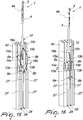
- the blending region 10 can be formed at least partly by a block that is fixed to the shank 2, as in the embodiment shown in Figures 1 to 12 .
- the upper portion of the blending region 10 is formed directly in the shank 2, while the remaining portion of the blending region 10 is obtained, as a continuation of the upper portion, in a block that is fixed rigidly to the shank 2.
- the blending region 10 can be obtained monolithically with the shank 2, as in the constructive variation of the needle according to the invention shown in Figure 13 .
- the upper ends 12a, 12b of the portions 8a, 8b of the laminas 6a, 6b are inserted slidingly within a slot 19 that is open at the front and in a downward region proximate to the base of the blending region 10.
- the first segment 13a, 13b of the portion 8a, 8b of the laminas 6a, 6b has a rear protrusion 22a, 22b, so as to allow said first portion 13a, 13b to engage in any case the sides 10a, 10b of the blending regions 10 of adjacent needles, provided like the needle 1, as a consequence of a longitudinal movement of the needle 1 with respect to the adjacent needles.
- the blending region 10 is not provided with the inclined lateral sides, since the shank 2, at said blending region 10, has sides that are mutually parallel.
- the blending region 10 is formed only by the front face 10c, which is inclined with respect to the longitudinal axis of the shank 2, so as to blend at the front the region occupied by the portions 8a, 8b of the laminas 6a, 6b with the portion of the shank 2 located above.
- the upper ends 12a, 12b of the portions 8a, 8b of the laminas 6a, 6b are inserted slidingly within recesses 19a, 19b formed in the sides of the shank 2, in a manner similar to the embodiment shown in Figures 1 to 12 .
- the needle is provided substantially as in the second constructive variation, shown in Figures 15 and 16 , with the difference that the two laminas 6a, 6b are provided monolithically instead of in two separate portions.
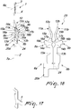
- the laminas 6a, 6b are obtained by means of a single portion 23 formed by blanking, shown in Figure 18 , and folded along the line 24.
- the blanked portion 23 is further bent to provide the first segment 13a, 13b and the third segment 15a, 15b.
- the laminas 6a, 6b are obtained by means of a single portion 25 formed by blanking, shown in Figure 20 , and folded along the line 26.
- the blanked portion 25 is further bent to provide the first segment 13a, 13b and the third segment 15a, 15b.
- the portion of the shank 2 that lies between the portion 8a, 8b of the lamina 6a, 6b above the blending region 10 and the head 3 has a front cutout that reduces the front space occupation of the shank 2 so as to avoid its interference with the rear protrusion 18a, 18b of the portion 8a, 8b of the lamina 6a, 6b of the adjacent needle during the transfer of the loop of knitting 9.
- the needles that are adjacent to the needle 1, which must release the stitch or loop of knitting 9, have been designated by the reference numerals 1a, 1b, but can be provided, as shown, like the needle 1 described up to now.
- the needle 1, arranged between the needles 1b, 1a is the needle that carries the loop of knitting 9 and must release it to the adjacent needle 1b, while the other needle 1a, arranged on the opposite side with respect to the needle 1b relative to the needle 1, is not affected by the transfer of the loop of knitting 9.
- the needle 1 is referenced hereinafter also as “releasing needle”
- the needle 1b is also referenced as “receiving needle”
- the needle 1a is also referenced as "inactive needle”.
- the needle 1 After forming the loop of knitting 9 and after knocking over the loop of knitting formed previously, is raised, by means of the needle actuation cams with which its heel 5 engages, so as to protrude for a segment above the knitting formation plane 21, which, as is known, is formed by the sinkers, not shown for the sake of simplicity in Figures 5 to 9 , which retain the loops of knitting 9 that have just been formed.
- the extent of the lifting of the needle 1, which must release the loop of knitting 9, is such as to bring the portion 8a, 8b of the laminas 6a, 6b at the knitting formation plane 21 and extract the portion 8a, 8b completely from the region that is occupied by the so-called "strips" that delimit laterally the seats, constituted by axial slots of the lateral surface of the needle cylinder 40, in which the needles slide.
- the laminas 6a, 6b first pressed against the shank 2 of the releasing needle 1 by the presence of the strips, move away by elastic reaction from the shank 2 with their portion 8a, 8b, which thus passes into the active position.
- the shank 2 of the needle 1 slides within the loop of knitting 9, which, being crossed first by the blending region 10 and then by the portion 8a, 8b of the laminas 6a, 6b up to the resting shoulder 17a, 17b, is widened progressively in a manner in which it is suitable to be crossed at least by the receiving needle 1b.
- the presence of the blended region 10 ensures a gradual expansion of the loop of knitting 9, avoiding excessive stresses both of the loop and of the laminas 6a, 6b.
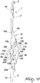
- the receiving needle 1b onto which the loop of knitting 9 is to be transferred, is moved upward with respect to the releasing needle 1, so as to insert its open head 3 in the space comprised between the portion 8b and the shank 2 of the releasing needle 1. It should be noted that the receiving needle 1b, in this lifting, is arranged with its head 3 between the rear protrusion 18b and the side 7b of the shank 2 of the releasing needle 1.
- the receiving needle 1b prevents the portion 8b of the lamina 6b from being crushed completely by the loop of knitting 9 against the side 7b of the shank 2 of the releasing needle 1 and the first segment 13b defines a front abutment that prevents the latch 4 of the receiving needle 1b from rotating about the axis 4a, assuredly keeping open the latch 4 of the receiving needle 1b, as shown in particular in Figure 7 .
- the inactive needle 1a is in a lower position with respect to the position occupied by the receiving needle 1b, but its head 3 is in any case preferably arranged between the rear protrusion 18a and the side 7a of the shank 2, and is thus "covered” by the rear protrusion 18a, so as to not interfere with the process for transferring the loop of knitting 9, as shown in particular in Figure 8 .
- the releasing needle 1 is lowered and the receiving needle 1b is lifted, preferably to the position that corresponds to the held-stitch position.
- the descent of the releasing needle 1 moves the receiving needle 1b so that it protrudes with its head upward from the portion 8b of the lamina 6b. Moreover, the descent of the needle 1 causes the loop of knitting 9, arranged around the laminas 6a, 6b, to slide along the third segment 15b of the portion 8b, moving it toward the shank 2 and bringing it into the head of the receiving needle 1b.
- the head 3 of the receiving needle 1b protrudes upward from the portion 8b of the lamina 6b practically without interfering with the portion 8b of the lamina 6b of the releasing needle 1 and therefore without the need to produce the separation of its upper end from the shank 2 of the releasing needle 1. In this manner, the wear of the head 3 of the receiving needle 1b and of the lamina 6b of the releasing needle 1 is reduced significantly.
- the two needles 1 and 1b can be lowered together below the knitting formation plane 21. During this lowering, the portions 8a, 8b of the laminas 6a, 6b, by engaging the strips, are moved into the inactive position.
- the passage of the portions 8a, 8b of the laminas 6a, 6b from the active position to the inactive position after the transfer of the loop of knitting 9 can be achieved following the descent of the releasing needle 1 between the adjacent needles 1a, 1b, since the first segment 13a, 13b of the portions 8a, 8b of the laminas 6a, 6b engages the sides 10a, 10b of the blending region 10, as shown in Figures 10 and 11 .
- the inactive needle 1a which does not take part in the transfer of the loop of knitting 9, can be used to reduce the extent of the elastic deformation of the portion 8a of the lamina 6a of the adjacent releasing needle 1 away from the corresponding side 7a of the releasing needle 1, so as to reduce the stresses to which the loop of knitting 9 to be transferred and the other lamina 6b are subjected.
- the releasing needle 1 and the inactive needle 1a are lifted together, so that the releasing needle 1 slides within the loop of knitting 9 until it is moved against the resting shoulder 17b of the lamina 6b, whose portion 8b is in the active position, while the contact of the blending region 10 of the inactive needle 1a continues to limit the spacing of the portion 8a of the lamina 6a from the side 7a of the releasing needle 1.
- Figure 12 illustrates the sequence of actuation, in the direction indicated by the arrow 30, of sets of three needles 1, 1a, 1b.
- the needles have all been shown with the corresponding latch 4 open, without altering the fact that the latch 4 is open or closed on the head of the needles 3 depending on the operating conditions of the needles.
- the sinkers 29 and/or the strips 27 engage the rear protrusion 18a, 18b of the second portion 14a, 14b of the portions 8a, 8b of the laminas 6a, 6b, assuredly preventing a compression of the portions 8a, 8b toward the shank 2 of the releasing needle 1 by virtue of the action of the loop of knitting 9.
- the needles according to the invention are used in a dial of a machine with cylinder and dial, the needles are moved radially outward instead of being raised and radially inward instead of being lowered.
- the particular structure of the needle according to the invention allows to provide said needle according to the invention with a reduced thickness, such as to allow its use in machines with high fineness (higher than 18 needles per inch).
- the needle according to the invention can be used advantageously also on double-bed machines to transfer a stitch from one bed to the other also with transfer from one needle of one bed to an adjacent needle of the same bed without requiring relative movements between the beds and therefore avoiding the problems of precision and complexity in execution that these movements entail.
- needles according to the invention with the possibility to transfer the stitches from either side of the needles on machines that can be actuated with an alternating motion allows to produce items of knitting with knitted regions of any shape with increasing or decreasing stitches, increasing their quality and degree of finish.
- the needle according to the invention fully achieves the intended aim, since by limiting the sliding between the elastically flexible portion of the laminas and the head of the adjacent needle onto which the stitch or loop of knitting is to be transferred it reduces the wear of these components, achieving longer durability for the needle.
- the covering of the head of the adjacent needles by the elastically flexible portion of the lamina of the releasing needle during the transfer of the stitch or loop of knitting ensures high precision and reliability in the operation for transferring the stitch or loop of knitting.
- Another advantage of the needle according to the invention is that it can prevent the compression of the elastically flexible portions of the lamina against the shank of the needle thanks to the action of the stitch or loop of knitting to be transferred and/or prevent or limit the spacing of the elastically flexible portions of the lamina from the shank of the needle that must release the stitch or loop of knitting by means of the adjacent needle or by means of other elements of the machine on which it is mounted, achieving high versatility in actuation and use.
- the materials used, as well as the dimensions, may be any according to requirements and to the state of the art.
Landscapes
- Engineering & Computer Science (AREA)
- Textile Engineering (AREA)
- Knitting Machines (AREA)
Claims (15)
- Eine Nadel (1) zur Maschenübertragung davon auf benachbarte Nadeln (1a, 1b) für Wirkmaschinen oder dergleichen, die Folgendes umfasst: einen Schaft (2), einen Kopf (3), der an einem Längs- oder oberen Ende des Schafts (2) angeordnet und wie ein Haken geformt ist, der zur Vorderseite des Schafts (2) hin offen ist, und eine Klinke (4), die drehgelenkig nahe dem Kopf (3) um eine Schwenkachse (4a) mit dem Schaft (2) verbunden ist, welche im Wesentlichen senkrecht zur Längsachse des Schafts (2) ist, und drehbar um die Schwenkachse (4a) zum Öffnen oder Schließen des Kopfs (3), mindestens ein Plättchen (6a, 6b), das mit dem Schaft (2) verbunden ist und auf jeder der beiden gegenüberliegenden Seiten (7a, 7b) des Schafts (2), unterhalb der Klinke (4), einen Abschnitt (8a, 8b) hat, der sich elastisch aus einer inaktiven Position, in welcher er näher an der entsprechenden Seite (7a, 7b) des Schafts (2) liegt, in eine aktive Position biegen kann, in welcher er von der entsprechenden Seite (7a, 7b) des Schafts (2) beabstandet ist; wobei in der aktiven Position der elastisch biegsame Abschnitt (8a, 8b) des Plättchens (6a, 6b) geeignet ist, eine Erweiterung einer Wirkschlaufe (9) zu bilden, die an dem elastisch biegsamen Abschnitt (8a, 8b) des Plättchens (6a, 6b) auf den Schaft (2) aufgesetzt ist; wobei der Kopf (3) einer benachbarten Nadel (1b) in der aktiven Position in den Raum zwischen dem elastisch biegsamen Abschnitt (8a, 8b) des Plättchens (6a, 6b) und der entsprechenden Seite (7a, 7b) des Schafts (2) einsetzbar ist, zum Aufnehmen der Wirkschlaufe (9) mit Hilfe der benachbarten Nadel (1b); wobei der elastisch biegsame Abschnitt (8a, 8b) des Plättchens (6a, 6b) einen Bereich hat, der seitlich, auf der Seite, die der entsprechenden Seite (7a, 7b) des Schafts (2) gegenüberliegt, auf den Kopf (3) der benachbarten Nadel (1b) gelegt werden kann, der in der aktiven Position in den Raum zwischen dem elastisch biegsamen Abschnitt (8a, 8b) des Plättchens (6a, 6b) und der entsprechenden Seite (7a, 7b) des Schafts (2) eingesetzt ist; dadurch gekennzeichnet, dass
das Plättchen (6a, 6b) mindestens mit dem Ende (12a, 12b), das dem Kopf (3) zugewandt ist, an der entsprechenden Seite (7a, 7b) des Schafts (2) in einem Bereich anliegt, der sich vor dem Kopf (3) befindet, so dass der Abstand zwischen der Längsachse des Schafts (2) des Endes (12a, 12b) des Plättchens (6a, 6b), das dem Kopf (3) zugewandt ist, größer ist als der Abstand zwischen der freien Spitze des Hakens und der Längsachse des Schafts (2). - Die Nadel (1) gemäß Anspruch 1, dadurch gekennzeichnet, dass das Plättchen (6a, 6b) für jede Seite (7a, 7b) des Schafts (2) einen unteren Bereich (20a, 20b) hat, der haftend an der entsprechenden Seite (7a, 7b) des Schafts (2) anliegt und daran befestigt ist; einen intermediären Bereich, der den elastisch biegsamen Abschnitt (8a, 8b) des Plättchens (6a, 6b) bildet, und einen oberen Bereich (11a, 11b), der an dem oberen Ende (12a, 12b) des Plättchens (6a, 6b) endet, das an der entsprechenden Seite (7a, 7b) des Schafts (2) anliegt.
- Die Nadel gemäß einem oder mehreren der obigen Ansprüche, dadurch gekennzeichnet, dass der elastisch biegsame Abschnitt (8a, 8b) des Plättchens (6a, 6b), ausgehend von seinem unteren Ende und in Abwesenheit darauf einwirkender Kräfte, aus Folgendem besteht: einem ersten Segment (13a, 13b), das von der entsprechenden Seite (7a, 7b) des Schafts (2) fort geknickt ist; einem zweiten Segment (14a, 14b), das im Wesentlichen parallel zur entsprechenden Seite (7a, 7b) des Schafts (2) ist; und einem dritten Segment (15a, 15b), das zur entsprechenden Seite (7a, 7b) des Schafts (2) hin geknickt ist; wobei das dritte Segment (15a, 15b) weiter vorne angeordnet ist als der Kopf (3).
- Die Nadel gemäß Anspruch 3, dadurch gekennzeichnet, dass das erste Segment (13a, 13b) des elastisch biegsamen Abschnitts (8a, 8b) des Plättchens (6a, 6b), mindestens nahe dem zweiten Segment (14a, 14b) des elastisch biegsamen Abschnitts (8a, 8b) des Plättchens (6a, 6b), weiter vorne angeordnet ist als der Kopf (3).
- Die Nadel gemäß einem der obigen Ansprüche 3 oder 4,
dadurch gekennzeichnet, dass der Bereich, der seitlich auf den Kopf (3) der benachbarten Nadel (1b) gelegt werden kann, durch einen hinteren Vorsprung (18a, 18b) des zweiten Segments (14a, 14b) des elastisch biegsamen Abschnitts (8a, 8b) des Plättchens (6a, 6b) bestimmt ist. - Die Nadel gemäß einem oder mehreren der Ansprüche 3 bis 5, dadurch gekennzeichnet, dass die Rückseite des ersten Segments (13a, 13b) des elastisch biegsamen Abschnitts (8a, 8b) des Plättchens (6a, 6b) ein Widerlager für die Klinke (4) der benachbarten Nadel (1b) bestimmt, das der Drehung seiner Klinke (4) um ihre Schwenkachse (4a) mit Bezug auf den Schaft (2) der benachbarten Nadel (1b) entgegenwirkt.
- Die Nadel gemäß einem oder mehreren der obigen Ansprüche, dadurch gekennzeichnet, dass der elastisch biegsame Abschnitt (8a, 8b) des Plättchens (6a, 6b) an seiner Vorderseite eine Stützschulter für die Wirkschlaufe hat.
- Die Nadel gemäß Anspruch 7 und einem der Ansprüche 3 bis 6,
dadurch gekennzeichnet, dass die Stützschulter durch die Oberseite eines vorderen Vorsprungs (16a, 16b) des zweiten Segments (14a, 14b) des elastisch biegsamen Abschnitts (8a, 8b) des Plättchens (6a, 6b) bestimmt ist. - Die Nadel gemäß einem oder mehreren der obigen Ansprüche, dadurch gekennzeichnet, dass der elastisch biegsame Abschnitt (8a, 8b) des Plättchens (6a, 6b) in Elemente der Maschine eingreifen kann, die seitlich von der Nadel (1) angeordnet sind, um den elastisch biegsamen Abschnitt (8a, 8b) des Plättchens (6a, 6b) in der inaktiven Position zu halten oder dorthin zu überführen; und zur Überführung des elastisch biegsamen Abschnitts (8a, 8b) des Plättchens (6a, 6b) in die aktive Position von den Elementen der Maschine getrennt werden kann.
- Die Nadel gemäß einem oder mehreren der obigen Ansprüche, dadurch gekennzeichnet, dass der elastisch biegsame Abschnitt (8a, 8b) des Plättchens (6a, 6b) in Elemente der Maschine eingreifen kann, die seitlich von der Nadel (1) angeordnet sind, um den elastisch biegsamen Abschnitt (8a, 8b) des Plättchens (6a, 6b) in der aktiven Position zu halten.
- Die Nadel gemäß einem oder mehreren der obigen Ansprüche, dadurch gekennzeichnet, dass der elastisch biegsame Abschnitt (8a, 8b) des Plättchens (6a, 6b) in die Seite (7) einer benachbarten Nadel (1b) eingreifen kann, um den elastisch biegsamen Abschnitt (8a, 8b) des Plättchens (6a, 6b) in die inaktive Position zu überführen oder dort zu halten.
- Die Nadel gemäß einem oder mehreren der obigen Ansprüche, dadurch gekennzeichnet, dass der elastisch biegsame Abschnitt (8a, 8b) des Plättchens (6a, 6b) in die Seite des Sitzes eingreifen kann, der im Nadelhalter (40) der Maschine geformt ist und dazu dient, die Nadel (1) aufzunehmen, um den elastisch biegsamen Abschnitt (8a, 8b) des Plättchens (6a, 6b) in die inaktive Position zu überführen oder dort zu halten.
- Die Nadel gemäß einem oder mehreren der obigen Ansprüche, dadurch gekennzeichnet, dass der elastisch biegsame Abschnitt (8a, 8b) des Plättchens (6a, 6b) in den Abschnitt des Nadelhalters (40) eingreifen kann, der die Seite des Sitzes bestimmt, der eine benachbarte Nadel aufnimmt, um den elastisch biegsamen Abschnitt (8a, 8b) des Plättchens (6a, 6b) in der aktiven Position zu halten.
- Die Nadel gemäß einem oder mehreren der obigen Ansprüche, dadurch gekennzeichnet, dass der Schaft (2) zwischen der Klinke (4) und dem Ende des elastisch biegsamen Abschnitts (8a, 8b) des Plättchens (6a, 6b), das dem Kopf (3) zugewandt ist, einen Bereich (10) hat, in dem der Schaft (2) in den elastisch biegsamen Abschnitt (8a, 8b) des Plättchens (6a, 6b) übergeht.
- Die Nadel gemäß Anspruch 14, dadurch gekennzeichnet, dass der Übergangsbereich (10) wie ein Keil geformt ist, der zu dem Kopf (3) der Nadel (1) hin spitz zuläuft.
Applications Claiming Priority (2)
| Application Number | Priority Date | Filing Date | Title |
|---|---|---|---|
| IT000121A ITMI20080121A1 (it) | 2008-01-28 | 2008-01-28 | Ago per operare il trasferimento di punti di maglia dallo stesso ago ad aghi adiacenti per macchine per maglieria, calzetteria o simili. |
| PCT/EP2009/050802 WO2009095359A1 (en) | 2008-01-28 | 2009-01-23 | Needle for transferring stitches from the needle itself to adjacent needles for hosiery knitting machines or the like |
Publications (2)
| Publication Number | Publication Date |
|---|---|
| EP2240634A1 EP2240634A1 (de) | 2010-10-20 |
| EP2240634B1 true EP2240634B1 (de) | 2019-06-26 |
Family
ID=40290136
Family Applications (1)
| Application Number | Title | Priority Date | Filing Date |
|---|---|---|---|
| EP09706885.2A Active EP2240634B1 (de) | 2008-01-28 | 2009-01-23 | Nadel zur maschenübertragung von der nadel selbst auf benachbarte nadeln für wirkmaschinen oder dergleichen |
Country Status (5)
| Country | Link |
|---|---|
| EP (1) | EP2240634B1 (de) |
| KR (1) | KR20100110861A (de) |
| CN (1) | CN101939473B (de) |
| IT (1) | ITMI20080121A1 (de) |
| WO (1) | WO2009095359A1 (de) |
Families Citing this family (2)
| Publication number | Priority date | Publication date | Assignee | Title |
|---|---|---|---|---|
| CN111286863A (zh) * | 2020-01-14 | 2020-06-16 | 冯加林 | 一种织针 |
| EP3889330B1 (de) | 2020-04-01 | 2023-08-23 | Groz-Beckert KG | Textilwerkzeugteilepaar und verfahren zur bestückung einer textilmaschine |
Family Cites Families (7)
| Publication number | Priority date | Publication date | Assignee | Title |
|---|---|---|---|---|
| US2997865A (en) * | 1961-08-29 | Philip | ||
| US3584481A (en) * | 1969-03-06 | 1971-06-15 | Teihichi Kayashi | Knitting needle for transferring stitches |
| IT8321328U1 (it) * | 1983-03-30 | 1984-09-30 | Santoni & C Spa | Ago del piatto composito per macchina circolare monocilindrica per calzetteria atta a produrre maglia a costa. |
| JP2724676B2 (ja) * | 1994-03-17 | 1998-03-09 | 株式会社島精機製作所 | 横編機 |
| US6321578B1 (en) * | 2001-02-28 | 2001-11-27 | Francesco Gavagnin Apollonio | Method and apparatus for transferring a loop from a selected needle to an adjacent needle for creating a decorative open-work pattern with no-run stitch and loop transfer knitting needle |
| DE10227533C1 (de) * | 2002-06-20 | 2003-12-11 | Groz Beckert Kg | Nadel mit Umhängefeder |
| WO2007057041A1 (en) * | 2005-11-18 | 2007-05-24 | Santoni S.P.A. | Needle for transferring stitches therefrom to adjacent needles for hosiery knitting machines or the like |
-
2008
- 2008-01-28 IT IT000121A patent/ITMI20080121A1/it unknown
-
2009
- 2009-01-23 KR KR1020107017457A patent/KR20100110861A/ko not_active Ceased
- 2009-01-23 EP EP09706885.2A patent/EP2240634B1/de active Active
- 2009-01-23 WO PCT/EP2009/050802 patent/WO2009095359A1/en not_active Ceased
- 2009-01-23 CN CN2009801038041A patent/CN101939473B/zh not_active Expired - Fee Related
Non-Patent Citations (1)
| Title |
|---|
| None * |
Also Published As
| Publication number | Publication date |
|---|---|
| ITMI20080121A1 (it) | 2009-07-29 |
| CN101939473B (zh) | 2013-03-27 |
| WO2009095359A1 (en) | 2009-08-06 |
| CN101939473A (zh) | 2011-01-05 |
| KR20100110861A (ko) | 2010-10-13 |
| EP2240634A1 (de) | 2010-10-20 |
Similar Documents
| Publication | Publication Date | Title |
|---|---|---|
| EP1247887B1 (de) | Platinen vorrichtung für flachstrickmaschine | |
| EP1054089B1 (de) | Verfahren zur Herstellung von schlauchförmigen Waren, sowie Strumpfwaren und dergleichen, welche an einem axialen Ende geschlossen sind, unter Verwendung einer Einzelzylinder-Rundstrickmaschine | |
| EP3165651B1 (de) | Flachstrickmaschine | |
| EP2240634B1 (de) | Nadel zur maschenübertragung von der nadel selbst auf benachbarte nadeln für wirkmaschinen oder dergleichen | |
| EP2240635B9 (de) | Nadel zur übertragung von maschen von der nadel selbst auf benachbarte nadeln für strumpfstrickmaschinen oder ähnlichem | |
| EP2002043B1 (de) | Zweizylindrige rundstrickmaschine für miederwaren und andere strickwaren | |
| EP2240636B1 (de) | Nadel zur übertragung von maschen von der nadel selbst auf benachbarte nadeln in strumpfstrickmaschinen oder ähnlichem | |
| EP1948859B1 (de) | Nadel zur übergabe von maschen an benachbarte nadeln für strick- oder wirkmaschinen oder dergleichen | |
| EP3165652B1 (de) | Strickverfahren und rundstrickmaschine | |
| EP1325973B1 (de) | Schuss-strickmaschine mit maschenübertragungsvorrichtung und verfahren zum übertragen von maschen | |
| HK1120575B (en) | Needle for transferring stitches therefrom to adjacent needles for hosiery knitting machines or the like | |
| JP5232862B2 (ja) | 円形靴下編み機における編み目の移動のためのプッシャー | |
| WO2012117351A1 (en) | Improved sinker for circular hosiery knitting machines, with high resistance to the danger of damage causable by contiguous needles | |
| CN101415871A (zh) | 用于袜类或类似物的圆型针织机 |
Legal Events
| Date | Code | Title | Description |
|---|---|---|---|
| PUAI | Public reference made under article 153(3) epc to a published international application that has entered the european phase |
Free format text: ORIGINAL CODE: 0009012 |
|
| 17P | Request for examination filed |
Effective date: 20100727 |
|
| AK | Designated contracting states |
Kind code of ref document: A1 Designated state(s): AT BE BG CH CY CZ DE DK EE ES FI FR GB GR HR HU IE IS IT LI LT LU LV MC MK MT NL NO PL PT RO SE SI SK TR |
|
| AX | Request for extension of the european patent |
Extension state: AL BA RS |
|
| 17Q | First examination report despatched |
Effective date: 20110321 |
|
| DAX | Request for extension of the european patent (deleted) | ||
| GRAP | Despatch of communication of intention to grant a patent |
Free format text: ORIGINAL CODE: EPIDOSNIGR1 |
|
| STAA | Information on the status of an ep patent application or granted ep patent |
Free format text: STATUS: GRANT OF PATENT IS INTENDED |
|
| INTG | Intention to grant announced |
Effective date: 20190110 |
|
| GRAS | Grant fee paid |
Free format text: ORIGINAL CODE: EPIDOSNIGR3 |
|
| GRAA | (expected) grant |
Free format text: ORIGINAL CODE: 0009210 |
|
| STAA | Information on the status of an ep patent application or granted ep patent |
Free format text: STATUS: THE PATENT HAS BEEN GRANTED |
|
| AK | Designated contracting states |
Kind code of ref document: B1 Designated state(s): AT BE BG CH CY CZ DE DK EE ES FI FR GB GR HR HU IE IS IT LI LT LU LV MC MK MT NL NO PL PT RO SE SI SK TR |
|
| REG | Reference to a national code |
Ref country code: GB Ref legal event code: FG4D |
|
| REG | Reference to a national code |
Ref country code: CH Ref legal event code: EP |
|
| REG | Reference to a national code |
Ref country code: DE Ref legal event code: R096 Ref document number: 602009058869 Country of ref document: DE |
|
| REG | Reference to a national code |
Ref country code: AT Ref legal event code: REF Ref document number: 1148390 Country of ref document: AT Kind code of ref document: T Effective date: 20190715 |
|
| REG | Reference to a national code |
Ref country code: IE Ref legal event code: FG4D |
|
| REG | Reference to a national code |
Ref country code: NL Ref legal event code: MP Effective date: 20190626 |
|
| PG25 | Lapsed in a contracting state [announced via postgrant information from national office to epo] |
Ref country code: HR Free format text: LAPSE BECAUSE OF FAILURE TO SUBMIT A TRANSLATION OF THE DESCRIPTION OR TO PAY THE FEE WITHIN THE PRESCRIBED TIME-LIMIT Effective date: 20190626 Ref country code: LT Free format text: LAPSE BECAUSE OF FAILURE TO SUBMIT A TRANSLATION OF THE DESCRIPTION OR TO PAY THE FEE WITHIN THE PRESCRIBED TIME-LIMIT Effective date: 20190626 Ref country code: FI Free format text: LAPSE BECAUSE OF FAILURE TO SUBMIT A TRANSLATION OF THE DESCRIPTION OR TO PAY THE FEE WITHIN THE PRESCRIBED TIME-LIMIT Effective date: 20190626 Ref country code: SE Free format text: LAPSE BECAUSE OF FAILURE TO SUBMIT A TRANSLATION OF THE DESCRIPTION OR TO PAY THE FEE WITHIN THE PRESCRIBED TIME-LIMIT Effective date: 20190626 Ref country code: NO Free format text: LAPSE BECAUSE OF FAILURE TO SUBMIT A TRANSLATION OF THE DESCRIPTION OR TO PAY THE FEE WITHIN THE PRESCRIBED TIME-LIMIT Effective date: 20190926 |
|
| REG | Reference to a national code |
Ref country code: LT Ref legal event code: MG4D |
|
| PG25 | Lapsed in a contracting state [announced via postgrant information from national office to epo] |
Ref country code: LV Free format text: LAPSE BECAUSE OF FAILURE TO SUBMIT A TRANSLATION OF THE DESCRIPTION OR TO PAY THE FEE WITHIN THE PRESCRIBED TIME-LIMIT Effective date: 20190626 Ref country code: GR Free format text: LAPSE BECAUSE OF FAILURE TO SUBMIT A TRANSLATION OF THE DESCRIPTION OR TO PAY THE FEE WITHIN THE PRESCRIBED TIME-LIMIT Effective date: 20190927 Ref country code: BG Free format text: LAPSE BECAUSE OF FAILURE TO SUBMIT A TRANSLATION OF THE DESCRIPTION OR TO PAY THE FEE WITHIN THE PRESCRIBED TIME-LIMIT Effective date: 20190926 |
|
| REG | Reference to a national code |
Ref country code: AT Ref legal event code: MK05 Ref document number: 1148390 Country of ref document: AT Kind code of ref document: T Effective date: 20190626 |
|
| PG25 | Lapsed in a contracting state [announced via postgrant information from national office to epo] |
Ref country code: CZ Free format text: LAPSE BECAUSE OF FAILURE TO SUBMIT A TRANSLATION OF THE DESCRIPTION OR TO PAY THE FEE WITHIN THE PRESCRIBED TIME-LIMIT Effective date: 20190626 Ref country code: PT Free format text: LAPSE BECAUSE OF FAILURE TO SUBMIT A TRANSLATION OF THE DESCRIPTION OR TO PAY THE FEE WITHIN THE PRESCRIBED TIME-LIMIT Effective date: 20191028 Ref country code: RO Free format text: LAPSE BECAUSE OF FAILURE TO SUBMIT A TRANSLATION OF THE DESCRIPTION OR TO PAY THE FEE WITHIN THE PRESCRIBED TIME-LIMIT Effective date: 20190626 Ref country code: NL Free format text: LAPSE BECAUSE OF FAILURE TO SUBMIT A TRANSLATION OF THE DESCRIPTION OR TO PAY THE FEE WITHIN THE PRESCRIBED TIME-LIMIT Effective date: 20190626 Ref country code: EE Free format text: LAPSE BECAUSE OF FAILURE TO SUBMIT A TRANSLATION OF THE DESCRIPTION OR TO PAY THE FEE WITHIN THE PRESCRIBED TIME-LIMIT Effective date: 20190626 Ref country code: AT Free format text: LAPSE BECAUSE OF FAILURE TO SUBMIT A TRANSLATION OF THE DESCRIPTION OR TO PAY THE FEE WITHIN THE PRESCRIBED TIME-LIMIT Effective date: 20190626 Ref country code: SK Free format text: LAPSE BECAUSE OF FAILURE TO SUBMIT A TRANSLATION OF THE DESCRIPTION OR TO PAY THE FEE WITHIN THE PRESCRIBED TIME-LIMIT Effective date: 20190626 |
|
| PG25 | Lapsed in a contracting state [announced via postgrant information from national office to epo] |
Ref country code: ES Free format text: LAPSE BECAUSE OF FAILURE TO SUBMIT A TRANSLATION OF THE DESCRIPTION OR TO PAY THE FEE WITHIN THE PRESCRIBED TIME-LIMIT Effective date: 20190626 Ref country code: IS Free format text: LAPSE BECAUSE OF FAILURE TO SUBMIT A TRANSLATION OF THE DESCRIPTION OR TO PAY THE FEE WITHIN THE PRESCRIBED TIME-LIMIT Effective date: 20191026 |
|
| PG25 | Lapsed in a contracting state [announced via postgrant information from national office to epo] |
Ref country code: DK Free format text: LAPSE BECAUSE OF FAILURE TO SUBMIT A TRANSLATION OF THE DESCRIPTION OR TO PAY THE FEE WITHIN THE PRESCRIBED TIME-LIMIT Effective date: 20190626 Ref country code: PL Free format text: LAPSE BECAUSE OF FAILURE TO SUBMIT A TRANSLATION OF THE DESCRIPTION OR TO PAY THE FEE WITHIN THE PRESCRIBED TIME-LIMIT Effective date: 20190626 |
|
| PG25 | Lapsed in a contracting state [announced via postgrant information from national office to epo] |
Ref country code: IS Free format text: LAPSE BECAUSE OF FAILURE TO SUBMIT A TRANSLATION OF THE DESCRIPTION OR TO PAY THE FEE WITHIN THE PRESCRIBED TIME-LIMIT Effective date: 20200224 |
|
| REG | Reference to a national code |
Ref country code: DE Ref legal event code: R097 Ref document number: 602009058869 Country of ref document: DE |
|
| PLBE | No opposition filed within time limit |
Free format text: ORIGINAL CODE: 0009261 |
|
| STAA | Information on the status of an ep patent application or granted ep patent |
Free format text: STATUS: NO OPPOSITION FILED WITHIN TIME LIMIT |
|
| PG2D | Information on lapse in contracting state deleted |
Ref country code: IS |
|
| 26N | No opposition filed |
Effective date: 20200603 |
|
| PG25 | Lapsed in a contracting state [announced via postgrant information from national office to epo] |
Ref country code: MC Free format text: LAPSE BECAUSE OF FAILURE TO SUBMIT A TRANSLATION OF THE DESCRIPTION OR TO PAY THE FEE WITHIN THE PRESCRIBED TIME-LIMIT Effective date: 20190626 Ref country code: SI Free format text: LAPSE BECAUSE OF FAILURE TO SUBMIT A TRANSLATION OF THE DESCRIPTION OR TO PAY THE FEE WITHIN THE PRESCRIBED TIME-LIMIT Effective date: 20190626 |
|
| REG | Reference to a national code |
Ref country code: CH Ref legal event code: PL |
|
| GBPC | Gb: european patent ceased through non-payment of renewal fee |
Effective date: 20200123 |
|
| REG | Reference to a national code |
Ref country code: BE Ref legal event code: MM Effective date: 20200131 |
|
| PG25 | Lapsed in a contracting state [announced via postgrant information from national office to epo] |
Ref country code: LU Free format text: LAPSE BECAUSE OF NON-PAYMENT OF DUE FEES Effective date: 20200123 Ref country code: FR Free format text: LAPSE BECAUSE OF NON-PAYMENT OF DUE FEES Effective date: 20200131 Ref country code: GB Free format text: LAPSE BECAUSE OF NON-PAYMENT OF DUE FEES Effective date: 20200123 |
|
| PG25 | Lapsed in a contracting state [announced via postgrant information from national office to epo] |
Ref country code: CH Free format text: LAPSE BECAUSE OF NON-PAYMENT OF DUE FEES Effective date: 20200131 Ref country code: LI Free format text: LAPSE BECAUSE OF NON-PAYMENT OF DUE FEES Effective date: 20200131 Ref country code: BE Free format text: LAPSE BECAUSE OF NON-PAYMENT OF DUE FEES Effective date: 20200131 |
|
| PG25 | Lapsed in a contracting state [announced via postgrant information from national office to epo] |
Ref country code: IE Free format text: LAPSE BECAUSE OF NON-PAYMENT OF DUE FEES Effective date: 20200123 |
|
| PG25 | Lapsed in a contracting state [announced via postgrant information from national office to epo] |
Ref country code: MT Free format text: LAPSE BECAUSE OF FAILURE TO SUBMIT A TRANSLATION OF THE DESCRIPTION OR TO PAY THE FEE WITHIN THE PRESCRIBED TIME-LIMIT Effective date: 20190626 Ref country code: CY Free format text: LAPSE BECAUSE OF FAILURE TO SUBMIT A TRANSLATION OF THE DESCRIPTION OR TO PAY THE FEE WITHIN THE PRESCRIBED TIME-LIMIT Effective date: 20190626 |
|
| PG25 | Lapsed in a contracting state [announced via postgrant information from national office to epo] |
Ref country code: MK Free format text: LAPSE BECAUSE OF FAILURE TO SUBMIT A TRANSLATION OF THE DESCRIPTION OR TO PAY THE FEE WITHIN THE PRESCRIBED TIME-LIMIT Effective date: 20190626 |
|
| PGFP | Annual fee paid to national office [announced via postgrant information from national office to epo] |
Ref country code: TR Payment date: 20230120 Year of fee payment: 15 Ref country code: IT Payment date: 20230113 Year of fee payment: 15 Ref country code: DE Payment date: 20230106 Year of fee payment: 15 |
|
| P01 | Opt-out of the competence of the unified patent court (upc) registered |
Effective date: 20230528 |
|
| REG | Reference to a national code |
Ref country code: DE Ref legal event code: R119 Ref document number: 602009058869 Country of ref document: DE |
|
| PG25 | Lapsed in a contracting state [announced via postgrant information from national office to epo] |
Ref country code: DE Free format text: LAPSE BECAUSE OF NON-PAYMENT OF DUE FEES Effective date: 20240801 |
|
| PG25 | Lapsed in a contracting state [announced via postgrant information from national office to epo] |
Ref country code: DE Free format text: LAPSE BECAUSE OF NON-PAYMENT OF DUE FEES Effective date: 20240801 |
|
| PG25 | Lapsed in a contracting state [announced via postgrant information from national office to epo] |
Ref country code: IT Free format text: LAPSE BECAUSE OF NON-PAYMENT OF DUE FEES Effective date: 20240123 |