EP2239898B1 - Transmission pilote par des postes de relais dans un système de communication de relais à plusieurs bonds - Google Patents
Transmission pilote par des postes de relais dans un système de communication de relais à plusieurs bonds Download PDFInfo
- Publication number
- EP2239898B1 EP2239898B1 EP10171144.8A EP10171144A EP2239898B1 EP 2239898 B1 EP2239898 B1 EP 2239898B1 EP 10171144 A EP10171144 A EP 10171144A EP 2239898 B1 EP2239898 B1 EP 2239898B1
- Authority
- EP
- European Patent Office
- Prior art keywords
- pilot
- station
- relay
- data
- format
- Prior art date
- Legal status (The legal status is an assumption and is not a legal conclusion. Google has not performed a legal analysis and makes no representation as to the accuracy of the status listed.)
- Active
Links
Images


Classifications
-
- H—ELECTRICITY
- H04—ELECTRIC COMMUNICATION TECHNIQUE
- H04L—TRANSMISSION OF DIGITAL INFORMATION, e.g. TELEGRAPHIC COMMUNICATION
- H04L5/00—Arrangements affording multiple use of the transmission path
- H04L5/003—Arrangements for allocating sub-channels of the transmission path
- H04L5/0048—Allocation of pilot signals, i.e. of signals known to the receiver
-
- H—ELECTRICITY
- H04—ELECTRIC COMMUNICATION TECHNIQUE
- H04B—TRANSMISSION
- H04B7/00—Radio transmission systems, i.e. using radiation field
- H04B7/14—Relay systems
- H04B7/15—Active relay systems
- H04B7/155—Ground-based stations
- H04B7/15557—Selecting relay station operation mode, e.g. between amplify and forward mode, decode and forward mode or FDD - and TDD mode
-
- H—ELECTRICITY
- H04—ELECTRIC COMMUNICATION TECHNIQUE
- H04L—TRANSMISSION OF DIGITAL INFORMATION, e.g. TELEGRAPHIC COMMUNICATION
- H04L1/00—Arrangements for detecting or preventing errors in the information received
- H04L1/0001—Systems modifying transmission characteristics according to link quality, e.g. power backoff
- H04L1/0023—Systems modifying transmission characteristics according to link quality, e.g. power backoff characterised by the signalling
- H04L1/0026—Transmission of channel quality indication
-
- H—ELECTRICITY
- H04—ELECTRIC COMMUNICATION TECHNIQUE
- H04L—TRANSMISSION OF DIGITAL INFORMATION, e.g. TELEGRAPHIC COMMUNICATION
- H04L1/00—Arrangements for detecting or preventing errors in the information received
- H04L1/12—Arrangements for detecting or preventing errors in the information received by using return channel
- H04L1/16—Arrangements for detecting or preventing errors in the information received by using return channel in which the return channel carries supervisory signals, e.g. repetition request signals
- H04L1/18—Automatic repetition systems, e.g. Van Duuren systems
- H04L1/1867—Arrangements specially adapted for the transmitter end
-
- H—ELECTRICITY
- H04—ELECTRIC COMMUNICATION TECHNIQUE
- H04L—TRANSMISSION OF DIGITAL INFORMATION, e.g. TELEGRAPHIC COMMUNICATION
- H04L25/00—Baseband systems
- H04L25/02—Details ; arrangements for supplying electrical power along data transmission lines
- H04L25/0202—Channel estimation
- H04L25/0224—Channel estimation using sounding signals
- H04L25/0226—Channel estimation using sounding signals sounding signals per se
-
- H—ELECTRICITY
- H04—ELECTRIC COMMUNICATION TECHNIQUE
- H04L—TRANSMISSION OF DIGITAL INFORMATION, e.g. TELEGRAPHIC COMMUNICATION
- H04L5/00—Arrangements affording multiple use of the transmission path
- H04L5/0001—Arrangements for dividing the transmission path
- H04L5/0028—Variable division
-
- H—ELECTRICITY
- H04—ELECTRIC COMMUNICATION TECHNIQUE
- H04L—TRANSMISSION OF DIGITAL INFORMATION, e.g. TELEGRAPHIC COMMUNICATION
- H04L5/00—Arrangements affording multiple use of the transmission path
- H04L5/0091—Signaling for the administration of the divided path
- H04L5/0094—Indication of how sub-channels of the path are allocated
-
- H—ELECTRICITY
- H04—ELECTRIC COMMUNICATION TECHNIQUE
- H04W—WIRELESS COMMUNICATION NETWORKS
- H04W48/00—Access restriction; Network selection; Access point selection
- H04W48/08—Access restriction or access information delivery, e.g. discovery data delivery
- H04W48/12—Access restriction or access information delivery, e.g. discovery data delivery using downlink control channel
-
- H—ELECTRICITY
- H04—ELECTRIC COMMUNICATION TECHNIQUE
- H04L—TRANSMISSION OF DIGITAL INFORMATION, e.g. TELEGRAPHIC COMMUNICATION
- H04L1/00—Arrangements for detecting or preventing errors in the information received
- H04L1/0001—Systems modifying transmission characteristics according to link quality, e.g. power backoff
- H04L1/0002—Systems modifying transmission characteristics according to link quality, e.g. power backoff by adapting the transmission rate
- H04L1/0003—Systems modifying transmission characteristics according to link quality, e.g. power backoff by adapting the transmission rate by switching between different modulation schemes
-
- H—ELECTRICITY
- H04—ELECTRIC COMMUNICATION TECHNIQUE
- H04L—TRANSMISSION OF DIGITAL INFORMATION, e.g. TELEGRAPHIC COMMUNICATION
- H04L1/00—Arrangements for detecting or preventing errors in the information received
- H04L1/0001—Systems modifying transmission characteristics according to link quality, e.g. power backoff
- H04L1/0009—Systems modifying transmission characteristics according to link quality, e.g. power backoff by adapting the channel coding
-
- H—ELECTRICITY
- H04—ELECTRIC COMMUNICATION TECHNIQUE
- H04L—TRANSMISSION OF DIGITAL INFORMATION, e.g. TELEGRAPHIC COMMUNICATION
- H04L1/00—Arrangements for detecting or preventing errors in the information received
- H04L1/004—Arrangements for detecting or preventing errors in the information received by using forward error control
- H04L1/0056—Systems characterized by the type of code used
- H04L1/0071—Use of interleaving
-
- H—ELECTRICITY
- H04—ELECTRIC COMMUNICATION TECHNIQUE
- H04L—TRANSMISSION OF DIGITAL INFORMATION, e.g. TELEGRAPHIC COMMUNICATION
- H04L1/00—Arrangements for detecting or preventing errors in the information received
- H04L2001/0092—Error control systems characterised by the topology of the transmission link
- H04L2001/0097—Relays
-
- H—ELECTRICITY
- H04—ELECTRIC COMMUNICATION TECHNIQUE
- H04L—TRANSMISSION OF DIGITAL INFORMATION, e.g. TELEGRAPHIC COMMUNICATION
- H04L25/00—Baseband systems
- H04L25/02—Details ; arrangements for supplying electrical power along data transmission lines
- H04L25/0202—Channel estimation
- H04L25/0224—Channel estimation using sounding signals
- H04L25/0228—Channel estimation using sounding signals with direct estimation from sounding signals
-
- H—ELECTRICITY
- H04—ELECTRIC COMMUNICATION TECHNIQUE
- H04L—TRANSMISSION OF DIGITAL INFORMATION, e.g. TELEGRAPHIC COMMUNICATION
- H04L27/00—Modulated-carrier systems
- H04L27/26—Systems using multi-frequency codes
- H04L27/2601—Multicarrier modulation systems
- H04L27/2626—Arrangements specific to the transmitter only
-
- H—ELECTRICITY
- H04—ELECTRIC COMMUNICATION TECHNIQUE
- H04L—TRANSMISSION OF DIGITAL INFORMATION, e.g. TELEGRAPHIC COMMUNICATION
- H04L27/00—Modulated-carrier systems
- H04L27/26—Systems using multi-frequency codes
- H04L27/2601—Multicarrier modulation systems
- H04L27/2647—Arrangements specific to the receiver only
-
- H—ELECTRICITY
- H04—ELECTRIC COMMUNICATION TECHNIQUE
- H04L—TRANSMISSION OF DIGITAL INFORMATION, e.g. TELEGRAPHIC COMMUNICATION
- H04L5/00—Arrangements affording multiple use of the transmission path
- H04L5/0001—Arrangements for dividing the transmission path
- H04L5/0014—Three-dimensional division
- H04L5/0023—Time-frequency-space
-
- H—ELECTRICITY
- H04—ELECTRIC COMMUNICATION TECHNIQUE
- H04L—TRANSMISSION OF DIGITAL INFORMATION, e.g. TELEGRAPHIC COMMUNICATION
- H04L5/00—Arrangements affording multiple use of the transmission path
- H04L5/003—Arrangements for allocating sub-channels of the transmission path
- H04L5/0032—Distributed allocation, i.e. involving a plurality of allocating devices, each making partial allocation
-
- H—ELECTRICITY
- H04—ELECTRIC COMMUNICATION TECHNIQUE
- H04W—WIRELESS COMMUNICATION NETWORKS
- H04W48/00—Access restriction; Network selection; Access point selection
- H04W48/08—Access restriction or access information delivery, e.g. discovery data delivery
-
- H—ELECTRICITY
- H04—ELECTRIC COMMUNICATION TECHNIQUE
- H04W—WIRELESS COMMUNICATION NETWORKS
- H04W84/00—Network topologies
- H04W84/02—Hierarchically pre-organised networks, e.g. paging networks, cellular networks, WLAN [Wireless Local Area Network] or WLL [Wireless Local Loop]
- H04W84/04—Large scale networks; Deep hierarchical networks
- H04W84/042—Public Land Mobile systems, e.g. cellular systems
- H04W84/047—Public Land Mobile systems, e.g. cellular systems using dedicated repeater stations
-
- H—ELECTRICITY
- H04—ELECTRIC COMMUNICATION TECHNIQUE
- H04W—WIRELESS COMMUNICATION NETWORKS
- H04W88/00—Devices specially adapted for wireless communication networks, e.g. terminals, base stations or access point devices
- H04W88/02—Terminal devices
- H04W88/04—Terminal devices adapted for relaying to or from another terminal or user
Definitions
- the present disclosure relates generally to communication, and more specifically to techniques for supporting multihop relay in a wireless communication system.
- Wireless communication systems are widely deployed to provide various communication services such as voice, video, packet data, messaging, broadcast, etc. These wireless systems may be multiple-access systems capable of supporting multiple users by sharing the available system resources. Examples of such multiple-access systems include Code Division Multiple Access (CDMA) systems, Time Division Multiple Access (TDMA) systems, Frequency Division Multiple Access (FDMA) systems, Orthogonal FDMA (OFDMA) systems, and Single-Carrier FDMA (SC-FDMA) systems.
- CDMA Code Division Multiple Access
- TDMA Time Division Multiple Access
- FDMA Frequency Division Multiple Access
- OFDMA Orthogonal FDMA
- SC-FDMA Single-Carrier FDMA
- Wireless systems have established themselves as a growing area in the field of telecommunications. The current trends and demands are to deliver multimedia services such as voice, video, interactive games, etc., with guaranteed Quality of Service (QoS). High data transmission capability is desirable in order to support high quality multimedia services.
- QoS Quality of Service
- a wireless communication system may support multihop relay in order to improve coverage and/or performance.
- a base station may transmit data to a subscriber station via one or more relay stations.
- Each relay station may receive the data from an upstream station (e.g., the base station or another relay station) and may retransmit the data to a downstream station (e.g., the subscriber station or another relay station).
- a transmission from one station to another station is considered as a hop. It may be desirable for each relay station to retransmit the data as efficiently as possible and in a manner that is transparent to the subscriber station.
- US 2006/098592 discloses a protocol communications system includes a processor, a bus, a memory, an RF section, and an integrated station device. An access point is detected based on information transmitted frequency channels using a protocol. Detection is initiated automatically during a power-on sequence or by activating an input device such as a button. Frequency channels are scanned for a beacon signal and an access point chosen as a preferred access point based on a metric such as power level.
- WO 2004/038985 discloses that a user terminal supports multiple spatial multiplexing (SM) modes such as a steered mode and a non-steered mode. For data transmission, multiple data streams are coded and modulated in accordance with their selected rates to obtain multiple data symbol streams.
- SM spatial multiplexing
- These streams are then spatially processed in accordance with a selected SM mode (e.g., with a matrix of steering vectors for the steered mode and with the identity matrix for the non-steered mode) to obtain multiple transmit symbol streams for transmission from multiple antennas.
- a selected SM mode e.g., with a matrix of steering vectors for the steered mode and with the identity matrix for the non-steered mode
- multiple received symbol streams are spatially processed in accordance with the selected SM mode (e.g., with a matrix of eigenvectors for the steered mode and with a spatial filter matrix for the non-steered mode) to obtain multiple recovered data symbol streams.
- These streams are demodulated and decoded in accordance with their selected rates to obtain multiple decoded data streams.
- the scheme is founded on a cross-layer paradigm, which enables a transmitting node to perform instant rate adaptation as well as to select among relays and among flows, thereby taking full advantage of the inherent multiuser diversity.
- the relative performance of MDF is benchmarked against two reference schemes, nearest with forward progress (NFP) and selection diversity forwarding (SDF).
- NFP forward progress
- SDF selection diversity forwarding
- the simulations indicate that the proposed scheme yields a substantial throughput increase.
- a radio communication apparatus is disclosed that enables the influence of the feedback information on the channel capacity to be kept to the minimum without reducing the transmission efficiency of information by transmission of pilot symbol.
- a delay dispersion measuring section generates a delay profile using the received signal, and measures delay dispersion indicative of dispersion of delayed versions.
- a moving speed estimating section estimates moving speed of a mobile station apparatus that transmits a pilot symbol based on the variation in reception power of the pilot symbol.
- Another-cell interference measuring section measures other-cell interference caused by signals transmitted in cells except the cell to which the apparatus belongs.
- a pilot pattern information generating section selects a pilot pattern such that placement of pilot symbol is optimal in a frame, and generates the pilot pattern information.
- EP 1 542 488 discloses that a set of different pilot structures are designed for use in different environments and/or different user behaviours that are expected to occur in a cell. The radio conditions for a user are estimated. Each user is then assigned an area (108A-E) in resource space for its communication, which has a suitable pilot configuration.
- the entire resource space is provided with different pilot structures in different parts (110A-D) in advance and allocation of resources to the users are then performed in order to match estimated radio conditions to the provided pilot structure.
- allocation is performed first, and then the actual pilot structure is adapted within the allocated resource space area to suit the environmental conditions.
- a CDMA system may implement a radio technology such as cdma2000, Universal Terrestrial Radio Access (UTRA), etc.
- An OFDMA system may implement a radio technology such as Ultra Mobile Broadband (UMB), Evolved UTRA (E-UTRA), IEEE 802.11 (which is also referred to as Wi-Fi), IEEE 802.16 (which is also referred to as WiMAX), IEEE 802.20, Flash-OFDM®, etc.
- UMB Ultra Mobile Broadband
- E-UTRA Evolved UTRA
- IEEE 802.11 which is also referred to as Wi-Fi
- IEEE 802.16 which is also referred to as WiMAX
- IEEE 802.20 Flash-OFDM®
- IEEE 802.16e entitled “Part 16: Air Interface for Fixed and Mobile Broadband Wireless Access Systems Amendment 2: Physical and Medium Access Control Layers for Combined Fixed and Mobile Operation in Licensed Bands," February 28, 2006
- IEEE 802.16j entitled “Part 16: Air Interface for Fixed and Mobile Broadband Wireless Access Systems Multihop Relay Specification,” December 24, 2007 .
- IEEE 802.16m covers multihop relay and is intended to enhance performance of IEEE 802.16 standards by introducing relay stations. Some objectives of IEEE 802.16j include extending coverage area, enhancing throughput and system capacity, saving battery life of subscriber stations, and minimizing complexity of relay stations.
- FIG. 1 shows a wireless communication system 100 that supports multihop relay.
- FIG. 1 shows only one base stations (BS) 110, three relay stations (RS) 120, 122 and 124, and two subscriber stations (SS) 130 and 132.
- a system may include any number of base stations and any number of relay stations that support communication for any number of subscriber stations.
- a base station is a station that supports communication for subscriber stations.
- a base station may perform functions such as connectivity, management, and control of relay stations and subscriber stations.
- a base station may also be referred to as a Node B, an evolved Node B, an access point, etc.
- a relay station is a station that provides connectivity to other relay stations and/or subscriber stations.
- a relay station may also provide management and control of subordinate relay stations and/or subscriber stations.
- the air interface between a relay station and a subscriber station may be identical to the air interface between a base station and a subscriber station.
- a base station may be coupled to a core network via a backhaul (not shown in FIG. 1 ) in order to support various services.
- a relay station may or may not be directly coupled to the backhaul and may have limited functionality to support multihop communication via that relay station.
- Subscriber stations may be dispersed throughout the system, and each subscriber station may be stationary or mobile.
- a subscriber station may also be referred to as a mobile station, a terminal, an access terminal, a user equipment, a subscriber unit, a station, etc.
- a subscriber station may be a cellular phone, a personal digital assistant (PDA), a wireless device, a wireless modem, a handheld device, a laptop computer, a cordless phone, etc.
- PDA personal digital assistant
- a subscriber station may communicate with a base station and/or a relay station via the downlink (DL) and uplink (UL).
- the downlink (or forward link) refers to the communication link from the base station or the relay station to the subscriber station.
- the uplink (or reverse link) refers to the communication link from the subscriber station to the base station or the relay station.
- base station 110 may communicate with subscriber station 130 via relay station 120.
- Base station 110 may transmit data for subscriber station 130 on the downlink.
- Relay station 120 may receive the data from base station 110 and may retransmit the data on the downlink to subscriber station 130.
- Base station 110 and subscriber station 130 may also be able to communicate directly with one another.
- Base station 110 may also communicate with subscriber station 132 via relay stations 122 and 124. Base station 110 may transmit data for subscriber station 132 on the downlink. Relay station 122 may receive the data from base station 110 and may retransmit the data to relay station 124. Relay station 124 may receive the data from relay station 122 and may retransmit the data on the downlink to subscriber station 132. Base station 110 may not be able to communicate directly with subscriber station 132 and may rely on one or more relay stations for communication with subscriber station 132.
- FIG. 1 shows an example of 2-hop communication between base station 110 and subscriber station 130.
- FIG. 1 also shows an example of 3-hop communication between base station 110 and subscriber station 132.
- a base station and a subscriber station may communicate via any number of hops.
- IEEE 802.16 utilizes orthogonal frequency division multiplexing (OFDM) for the downlink and uplink.
- OFDM partitions the system bandwidth into multiple (NFFT) orthogonal subcarriers, which may also be referred to as tones, bins, etc.
- NFFT multiple orthogonal subcarriers
- Each subcarrier may be modulated with data or pilot.
- the number of subcarriers may be dependent on the system bandwidth as well as the spacing between adjacent subcarriers.
- NFFT may be equal to 128, 256, 512, 1024 or 2048. Only a subset of the NFFT total subcarriers may be usable for transmission of data and pilot, and the remaining subcarriers may serve as guard subcarriers to allow the system to meet spectral mask requirements.
- a data subcarrier is a subcarrier used for data
- a pilot subcarrier is a subcarrier used for pilot.
- An OFDM symbol may be transmitted in each OFDM symbol period (or simply, a symbol period) and may include data subcarriers used to send data, pilot subcarriers used to send pilot, and guard subcarriers not used for data or pilot.
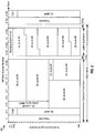
- FIG. 2 shows an example frame structure 200 without multihop relay for a time division duplex (TDD) mode in IEEE 802.16.
- the transmission timeline is partitioned into units of frames. Each frame spans a predetermined time duration, e.g., 5 milliseconds (ms), and is partitioned into a downlink subframe and an uplink subframe.
- the downlink and uplink subframes are separated by a transmit transmission gap (TTG) and a receive transmission gap (RTG).
- TTG transmit transmission gap
- RTG receive transmission gap
- a number of physical subchannels may be defined. Each physical subchannel includes a set of subcarriers that may be contiguous or distributed across the system bandwidth. A number of logical subchannels may also be defined and may be mapped to the physical subchannels based on a known mapping. The logical subchannels simplify the allocation of resources.
- a downlink subframe includes a preamble, a frame control header (FCH), a downlink map (DL-MAP), an uplink map (UL-MAP), and downlink (DL) bursts.
- the preamble may carry a known transmission that may be used by subscriber stations for frame detection and synchronization.
- the FCH may carry parameters used to receive the DL-MAP, the UL-MAP, and the downlink bursts.
- the DL-MAP may carry a DL-MAP message, which may include information elements (IEs) for various types of control information (e.g., resources allocation) for downlink access.
- the UL-MAP may carry a UL-MAP message, which includes IEs for various types of control information for uplink access.
- the downlink bursts may carry data for the subscriber stations being served.
- An uplink subframe may include uplink bursts, which may carry data from the subscriber stations scheduled for uplink transmission.
- the downlink and uplink subframes may cover any fraction of a frame.
- a frame includes 43 OFDM symbols
- the downlink subframe includes 27 OFDM symbols
- the uplink subframe includes 16 OFDM symbols.
- the frame, downlink subframe, and uplink subframe may also have other durations, which may be fixed or configurable.
- IEEE 802.16 supports FUSC, PUSC, and band AMC for data transmission on the downlink.
- each subchannel includes a set of subcarriers from across the system bandwidth.
- the subcarriers are arranged in groups, and each subchannel includes a set of subcarriers from across a single group.
- each subchannel includes a set of contiguous subcarriers.
- a downlink subframe may include zero or more FUSC zones, zero or more PUSC zones, and zero or more band AMC zones. Each zone includes all NFFT subcarriers in one or more consecutive OFDM symbols.
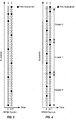
- FIG. 3 shows a subcarrier structure for FUSC.
- pilot subcarriers are located uniformly across the available subcarriers and are spaced apart by 12 subcarriers.
- the pilot subcarriers in the even-numbered OFDM symbols are staggered by six subcarriers from the pilot subcarriers in the odd-numbered OFDM symbols.
- Each OFDM symbol also includes a set of fixed pilot subcarriers (e.g., subcarriers 39, 261, ..., 1701). Of the remaining subcarriers, most are used for data and some are used as guard subcarriers.
- a subchannel includes 48 data subcarriers distributed across the system bandwidth.
- FIG. 4 shows a subcarrier structure for PUSC.
- the available subcarriers are arranged into clusters, with each cluster including 14 consecutive subcarriers.
- the fifth and ninth subcarriers in each cluster are pilot subcarriers, and the remaining 12 subcarriers are data subcarriers.
- the first and eleventh subcarriers in each cluster are pilot subcarriers, and the remaining 12 subcarriers are data subcarriers.
- the clusters are arranged into groups, with each group including 24 clusters. For PUSC, a subchannel includes 24 data subcarriers distributed across one group.
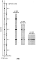
- FIG. 5 shows a subcarrier structure for band AMC.
- the available subcarriers are arranged into bins, with each bin including 9 consecutive subcarriers.
- the center subcarrier in each bin is a pilot subcarrier, and the remaining 8 subcarriers are data subcarriers.
- a subchannel may include one bin in six consecutive OFDM symbols, two bins in three consecutive OFDM symbols, or three bins in two consecutive OFDM symbols.
- a subscriber station may be assigned one or more slots for data transmission on the downlink.
- a slot is a minimum data allocation unit.
- FUSC a slot is one subchannel (with 48 data subcarriers) in one OFDM symbol.
- PUSC a slot is one subchannel (with 24 data subcarriers) in two OFDM symbols.
- band AMC a slot is 8, 16 or 24 data subcarriers in 6, 3 or 2 OFDM symbols, respectively.
- FIGS. 3, 4 and 5 show three pilot formats that may be used for sending pilot. Other pilot formats may also be defined.
- the pilot subcarriers may be staggered across OFDM symbols instead of being at the same location as shown in FIG. 5 . If multiple transmit antennas are used for transmission, then the same or different pilot formats may be used for these multiple transmit antennas.
- the slots, subchannels, and pilots for FUSC, PUSC, and band AMC are described in the aforementioned IEEE 802.16 documents.
- a base station may transmit data directly to a subscriber station using frame structure 200 in FIG. 2 .
- the subscriber station may perform frame detection and synchronization based on the preamble and obtain parameters from the FCH.
- the subscriber station may then process the DL-MAP to obtain a DL-MAP message that may indicate a downlink burst in slots assigned to the subscriber station.
- the subscriber station may then process the downlink burst to recover the data sent to the subscriber station.
- the subscriber station may first obtain a channel estimate for the data subcarriers in the downlink burst based on pilot sent on the pilot subcarriers.
- the location of the data and pilot subcarriers may be dependent on whether the data was sent using FUSC, PUSC, or band AMC.
- the subscriber station may then perform detection for the data subcarriers based on the channel estimate.
- the pilot subcarriers thus carry important information used by the subscriber station to recover the data.
- a base station may transmit data to a subscriber station via one or more relay stations.
- the system may support a transparent mode and a non-transparent mode.
- Table 1 lists some characteristics of the transparent mode and non-transparent mode, which are described in detail in the aforementioned IEEE 802.16j document.
- Table 1 Mode Description Transparent mode • Base station schedules transmission on the downlink, generates assignment messages, and coordinates retransmission by relay stations. • Relay station retransmits data received from the base station but does not transmit preamble, FCH or MAP. • Subscriber station receives assignment messages from the base station and receives data from the relay station.
- Non-transparent mode • Base station schedules transmission for the first hop. • Relay station can schedule retransmission for subsequent hop and generate assignment messages. Relay station retransmits data received from the base station and also transmits preamble, FCH and MAP. • Subscriber station receives assignment messages and data from the relay station.
- FIG. 6 shows a frame structure for multihop relay in the transparent mode.
- the top half of FIG. 6 shows a frame 610 for a base station, and the bottom half of FIG. 6 shows a frame 620 for a relay station. Only the downlink subframes of frames 610 and 620 are described below.
- the downlink subframe is partitioned into a downlink access zone 612 and an optional transparent zone 614.
- Each zone may include any number of OFDM symbols, which may be configurable and determined by the base station.
- downlink access zone 612 includes OFDM symbols k through k+10
- optional transparent zone 614 includes OFDM symbols k+11 through k+17.
- the base station transmits a preamble, an FCH, a DL-MAP, a UL-MAP, a relay MAP (R-MAP), and downlink bursts in downlink access zone 612, e.g., in similar manner as described above for FIG. 2 .
- the R-MAP may carry an R-MAP message that may convey the detailed allocation for the relay station in optional transparent zone 614.
- the base station may or may not transmit during optional transparent zone 614.
- the downlink subframe is also partitioned into a downlink access zone 622 and an optional transparent zone 624 that are time-aligned with downlink access zone 612 and optional transparent zone 614 of frame 610.
- Downlink access zone 622 and optional transparent zone 624 are separated by a relay receive/transmit transition gap (R-RTG), which is given in an integer number of OFDM symbols.
- R-RTG relay receive/transmit transition gap
- the relay station may receive the preamble, FCH, DL-MAP, UL-MAP, R-MAP, and downlink bursts from the base station during downlink access zone 622.
- the relay station may ignore downlink burst #6, which overlaps the R-RTG and may be intended for a subscriber station.
- the relay station may retransmit some or all of the data received from the base station in optional transparent zone 624 as indicated by the R-MAP message.
- the base station may send a DL-MAP message that conveys the downlink burst assigned to each subscriber station being served.
- Each subscriber station may receive the DL-MAP message from the base station and may process the assigned downlink burst, which may be transmitted by the base station or the relay station.
- a subscriber station may thus receive the preamble, FCH, and DL-MAP message from the base station but may receive data from the relay station.
- the relay station may receive the data from the base station and retransmit the data as indicated by the base station.
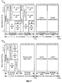
- FIG. 7 shows a frame structure for multihop relay in the non-transparent mode.
- the top half of FIG. 7 shows a frame 710 for a base station, and the bottom half of FIG. 7 shows a frame 720 for a relay station. Only the downlink subframes of frames 710 and 720 are described below.
- the downlink subframe is partitioned into a downlink access zone 712 and a downlink relay zone 714.
- Each zone includes any number of OFDM symbols, which may be configurable and determined by the base station.
- the base station may transmit a preamble, an FCH, a DL-MAP, a UL-MAP, and downlink bursts in downlink access zone 712 directly to subscriber stations.
- the base station may transmit a relay FCH (R-FCH), an R-MAP, and downlink bursts in downlink relay zone 714 to the relay station.
- R-FCH relay FCH
- the downlink subframe is also partitioned into a downlink access zone 722 and a downlink relay zone 724 that are time-aligned with downlink access zone 712 and downlink relay zone 714 of frame 710.
- the relay station may receive the R-FCH, R-MAP, and downlink bursts from the base station during downlink relay zone 724.
- the relay station may transmit a preamble, an FCH, a DL-MAP, a UL-MAP, and downlink bursts for some or all of the data received from the base station in downlink access zone 722 of the next frame. There is thus a delay of one frame for the data retransmitted by the relay station.
- the base station may send an R-MAP message that may convey the downlink burst for each relay station in downlink relay zone 714.
- the relay station may receive the data from the base station as indicated by the R-MAP message.
- the relay station may transmit a preamble, an FCH, a DL-MAP, a UL-MAP, and downlink bursts containing the data received from the base station in downlink access zone 722 to subscriber stations.
- the DL-MAP message may convey the downlink burst assigned by the relay station to each subscriber station.
- Each subscriber station may receive the preamble, the FCH, the DL-MAP message, and the data from the relay station and may not need to receive anything from the base station.
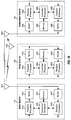
- FIG. 8 shows a frame structure for three hops in the non-transparent mode.
- the top of FIG. 8 shows a frame 810 for a base station
- the middle of FIG. 8 shows a frame 820 for a first relay station (RS1)
- the bottom of FIG. 8 shows a frame 830 for a second relay station (RS2).
- RS1 first relay station
- RS2 second relay station
- the downlink subframe is partitioned into a downlink access zone 812 and a downlink relay zone 816.
- Each zone may include any number of OFDM symbols.
- the base station transmits a preamble, an FCH, a DL-MAP, a UL-MAP, and downlink bursts in downlink access zone 812 directly to subscriber stations.
- the base station transmits an R-FCH, an R-MAP, and downlink bursts in downlink relay zone 816 to the first relay station.
- the downlink subframe is partitioned into a downlink access zone 822 and downlink relay zones 824 and 826.
- Downlink access zone 822 and downlink relay zone 824 are time-aligned with downlink access zone 812 of frame 810.
- Downlink relay zone 826 is time-aligned with downlink relay zone 816 of frame 810.
- the first relay station receives the R-FCH, the R-MAP, and the downlink bursts from the base station during downlink relay zone 826.
- the first relay station transmits a preamble, an FCH, a DL-MAP, a UL-MAP, and downlink bursts for some of the data received from the base station to subscriber stations in downlink access zone 822 of the next frame.
- the data sent by the first relay station in downlink access zone 822 may be for subscriber stations that do not need the second relay station.
- the first relay station may also retransmit some of the data received from the base station to the second relay station in downlink relay zone 824 of the next frame.
- the downlink subframe is partitioned into a downlink access zone 832 and a downlink relay zone 834.
- Downlink access zone 832 and downlink relay zone 834 are time-aligned with downlink access zone 822 and downlink relay zone 824 of frame 820.
- the second relay station receives data from the first relay station in downlink relay zone 834.
- the second relay station transmits a preamble, an FCH, a DL-MAP, a UL-MAP, and downlink bursts for the data received from the first relay station to subscriber stations in downlink access zone 832 of the next frame.
- FIG. 9 shows another frame structure for three hops in the non-transparent mode.
- the top of FIG. 9 shows a frame 910 for a base station
- the middle of FIG. 9 shows a frame 920 for a first relay station
- the bottom of FIG. 9 shows a frame 930 for a second relay station.
- the downlink subframe of frame 910 is partitioned into a downlink access zone 912 and a downlink relay zone 916.
- the base station may transmit overhead and data in zones 912 and 916, as described above for zones 812 and 816 in FIG. 8 .
- the downlink subframe of frame 920 is partitioned into a downlink access zone 922 and downlink relay zones 924 and 926.
- the first relay station receives data in zone 926 and transmits overhead and data in zones 922 and 924, as described above for zones 822, 824 and 826 in FIG. 8 .
- the downlink subframe is partitioned into a downlink access zone 932 and downlink relay zones 934 and 936.
- the second relay station receives data from the first relay station in downlink relay zone 934.
- the second relay station transmits a preamble, an FCH, a DL-MAP, a UL-MAP, and downlink bursts for the data received from the first relay station to subscriber stations in zones 932 and 936 of the next frame.
- FIGS. 8 and 9 show two frame structures that support three hops via two relay stations. For these frame structures, there is a delay of one frame for the data retransmitted by the first relay station, and a delay of one frame for the data retransmitted by the second relay station. More than two hops may be supported with other frame structures. More than three hops may also be supported, e.g., with more downlink relay zones. In general, there may be separate zones for base station to subscriber station (BS-SS) communication, relay station to relay station (RS-RS) communication, and relay station to subscriber station (RS-SS) communication.
- BS-SS base station to subscriber station
- RS-RS relay station to relay station
- RS-SS relay station to subscriber station
- a subscriber station receives the pilot sent by a base station and uses this pilot to perform channel estimation and report channel conditions.
- the base station is not sending pilot.
- the relay station itself generates the pilot for the subscriber station.
- a relay station receives data and a first pilot from an upstream station and retransmits the data and transmit a second pilot to a downstream station.
- the first pilot allows the relay station to recover the data from the upstream station.
- the second pilot allows the downstream station to recover the retransmitted data from the relay station.
- the first and second pilots may be transmitted in the same or different manners, depending on various factors such as the number of hops between a base station and a subscriber station, the order of the relay station in the multihop relay, etc.
- Each pilot may be transmitted in accordance with a pilot format that indicates how the pilot is to be transmitted.
- a pilot format may also be referred to as a pilot structure, a pilot scheme, etc.
- FIG. 10 shows a scheme for transmitting data and pilot in 2-hop relay.
- Base station 110 may transmit data and pilot to relay station 120, e.g., in downlink access zone 612 in FIG. 6 or downlink relay zone 714 in FIG. 7 .
- Base station 110 may transmit pilot using any of the pilot formats shown in FIGS. 3, 4 and 5 or using some other pilot format for the downlink bursts sent to relay station 120. Since the data and pilot in these downlink bursts are intended for relay station 120 and not for subscriber station 130, the pilot may be transmitted using a pilot format that is not supported by subscriber station 130.
- Relay station 120 may retransmit the data and may transmit pilot to subscriber station 130, e.g., in optional transparent zone 624 in FIG. 6 or downlink access zone 722 in FIG. 7 .
- Relay station 120 may transmit pilot using a pilot format supported by subscriber station 130, e.g., using the pilot format shown in FIG. 3, 4 or 5 depending on whether the data is retransmitted using FUSC, PUSC, or band AMC, respectively. This allows subscriber station 130 to receive the retransmitted data and pilot from relay station 120 in the same manner as if the data and pilot were transmitted by base station 110. Subscriber station 130 does not need to be aware of whether the data and pilot are coming from base station 110 or relay station 120.
- FIG. 11 shows a scheme for transmitting data and pilot in 3-hop relay.
- Base station 110 transmits data and pilot to relay station 122, e.g., in downlink relay zone 816 in FIG. 8 or downlink relay zone 916 in FIG. 9 .
- Base station 110 transmits pilot using any pilot format.
- Relay station 122 retransmits the data and transmits pilot to relay station 124, e.g., in downlink relay zone 824 in FIG. 8 or downlink relay zone 924 in FIG. 9 .
- Relay station 122 may also transmit pilot using any pilot format.
- Relay station 124 retransmits the data and transmits pilot to subscriber station 132, e.g., in downlink access zone 832 in FIG. 8 or downlink access zone 932 in FIG. 9 .
- Relay station 124 may transmit pilot using a pilot format supported by subscriber station 130.
- an upstream station e.g., a base station or a relay station transmits pilot to a downstream relay station using any pilot format.
- a relay station for the last hop transmits pilot using a pilot format supported by a subscriber station and in the same manner as the base station. The last relay station replicates the way the base station would send the pilot if the base station was transmitting.
- the pilot in the last hop may be dependent on whether data is resent using FUSC, PUSC, or band AMC.
- the pilot sent by a base station for BS-RS communication may be the same as the pilot sent by the base station for BS-SS communication or may be customized for the BS-RS communication and entirely different from the pilot for the BS-SS communication.
- the pilot sent by a relay station for RS-RS communication may be the same as the pilot sent by the base station for BS-SS communication or may be customized for the RS-RS communication and entirely different from the pilot for the BS-SS communication.
- the pilot sent by a relay station for RS-SS communication may be the same as the pilot sent by the base station for BS-SS communication.
- the pilot sent by an upstream station (e.g., a base station or a relay station) to a downstream relay station may be based on a pilot format determined by over-the-air negotiation between the two stations.
- the upstream station or the downstream relay station may send a signal, a message, or some other information to convey a pilot format to use for the pilot.
- pilot formats may be used for the pilot sent by the upstream station to the downstream relay station.
- the pilot may be global and sent on pilot subcarriers distributed across the system bandwidth.
- the pilot may also be local and sent on pilot subcarriers distributed across a portion of the system bandwidth.
- Local pilot may support frequency reuse of greater than one.
- the number of pilot subcarriers and the location of the pilot subcarriers in each OFDM symbol may be selected to provide good performance.
- the upstream station and the downstream relay station may observe good channel conditions. Hence, fewer pilot subcarriers may be sufficient to achieve good performance.
- the number of pilot subcarriers and the location of the pilot subcarriers may be static across all OFDM symbols or may change dynamically from OFDM symbol to OFDM symbol.
- the upstream station sends information indicative of a pilot format being used for the pilot sent to the downstream relay station.
- the downstream relay station receives the pilot in accordance with the pilot format indicated by the upstream station.
- the upstream station sends data and pilot in accordance with FUSC, PUSC, or band AMC mode.
- the downstream relay station may determine the pilot format based on the transmission mode used for the data.
- a downstream station uses the pilot received from an upstream station (e.g., a relay station or a base station) to perform channel estimation and obtain a channel estimate.
- the downstream station uses the channel estimate to perform detection/decoding of data received from the upstream station.
- the downstream station also obtains channel information based on the pilot.
- the channel information may comprise a carrier-to-interference-and-noise ratio (CINR), a modulation coding set (MCS), a channel quality indicator (CQI), etc.
- CINR carrier-to-interference-and-noise ratio
- MCS modulation coding set
- CQI channel quality indicator
- the channel information may be used by the upstream station or the downstream station for rate selection to select a rate for data transmission from the upstream station to the downstream station.
- FIG. 12 shows a design of a process 1200 performed by a relay station to support multihop relay.
- the relay station receives data and a first pilot from a first station (block 1212).
- the relay station derives a channel estimate based on the first pilot (block 1214) and then performs detection for the data received from the first station based on the channel estimate (block 1216).
- the relay station resends the data and send a second pilot to a second station (block 1218).
- the relay station receives channel information from the second station, with the channel information being derived by the second station based on the second pilot (block 1220).
- the relay station forwards the channel information to the first station and/or selects a rate for data transmission to the second station based on the channel information (block 1222).
- the first station may be a base station, and the second station may be a subscriber station.
- the first station may be a base station, and the second station may be another relay station.
- the first station may be another relay station, and the second station may be a subscriber station.
- the first and second stations may also be upstream and downstream relay stations, respectively.
- Each pilot may be sent on at least one pilot subcarrier in at least one OFDM symbol.
- the location of the at least one pilot subcarrier may be determined based on a pilot format for the pilot.
- the relay station receives the first pilot in accordance with a first pilot format and sends the second pilot in accordance with a second pilot format that is different from the first pilot format.
- the relay station receives the first pilot in accordance with a pilot format and may send the second pilot in accordance with the same pilot format used for the first pilot.
- the relay station receives from the first station information indicative of a pilot format for the first pilot.
- the relay station receives the first pilot in accordance with the pilot format.
- the relay station receives from the first station information indicative of a pilot format for the second pilot.
- the relay station may then send the second pilot in accordance with the pilot format.
- the relay station resends the data in accordance with a transmission mode selected from among multiple transmission modes (e.g., FUSC, PUSC, and band AMC). Each transmission mode may be associated with a different pilot format.
- the relay station may send the second pilot in accordance with the pilot format associated with the selected transmission mode.
- FIG. 13 shows a design of an apparatus 1300 for supporting multihop relay.
- Apparatus 1300 includes means for receiving data and a first pilot from a first station (module 1312), means for deriving a channel estimate based on the first pilot (module 1314), means for performing detection for the data received from the first station based on the channel estimate (module 1316), means for resending the data and sending a second pilot to a second station (module 1318), means for receiving channel information from the second station (module 1320), and means for forwarding the channel information to the first station and/or selecting a rate for data transmission to the second station based on the channel information (module 1322).
- FIG. 14 shows a design of a process 1400 performed by a subscriber station for receiving data with multihop relay.
- the subscriber station receives data and pilot from a relay station, with the data being sent from a base station to the subscriber station and resent by the relay station, and the pilot being sent directly from the relay station to the subscriber station (block 1412).
- the subscriber station performs detection for the data received from the relay station based on the pilot (block 1414).
- the subscriber station receives information indicative of a pilot format from the base station.
- the subscriber station receives information indicative of a pilot format from the relay station.
- the subscriber station receives the pilot from the relay station in accordance with the pilot format.
- the subscriber station receives information indicative of a transmission mode selected from among multiple transmission modes, with each transmission mode being associated with a different pilot format. The subscriber station may then receive the pilot from the relay station in accordance with the pilot format associated with the selected transmission mode.
- the subscriber station derives a channel estimate based on the pilot received from the relay station.
- the subscriber station then performs detection for the data received from the relay station based on the channel estimate.
- the subscriber station also determines channel information based on the pilot (block 1416) and sends the channel information to the relay station (block 1418).
- FIG. 15 shows a design of an apparatus 1500 for receiving data with multihop relay.
- Apparatus 1500 includes means for receiving data and pilot from a relay station, with the data being sent from a base station to a subscriber station and resent by the relay station, and the pilot being sent directly from the relay station to the subscriber station (module 1512), means for performing detection for the data received from the relay station based on the pilot (module 1514), means for determining channel information based on the pilot (module 1516), and means for sending the channel information to the relay station (module 1518).
- the modules in FIGS. 13 and 15 may comprise processors, electronics devices, hardware devices, electronics components, logical circuits, memories, etc., or any combination thereof.
- the techniques described herein may also be used for data transmission on the uplink from a subscriber station to a base station via one or more relay stations.
- the subscriber station may transmit data and a first pilot using a pilot format supported by the subscriber station.
- a relay station may receive the data and the first pilot from the subscriber station and may retransmit the data and transmit a second pilot to another relay station or a base station.
- the second pilot may be sent in any format supported by the relay station and the recipient station.
- FIG. 16 shows a block diagram of a design of base station 110, relay station 120, and subscriber station 130 in FIG. 1 .
- a transmit processor 1610 receives data for subscriber station 130 and other subscriber stations, processes (e.g., encodes, interleaves, and modulates) the data, and generates data symbols. Transmit processor 1610 also processes overhead information (e.g., MAP messages) and pilot to obtain overhead symbols and pilot symbols, respectively. Transmit processor 1610 further processes the data, overhead, and pilot symbols (e.g., for OFDM) and provides output chips.
- a transmitter (TMTR) 1612 conditions (e.g., converts to analog, amplifies, filters, and frequency upconverts) the output chips and generates a downlink signal, which is transmitted via an antenna 1614.
- TMTR transmitter
- an antenna 1634 receives the downlink signal from base station 110 and provides a received signal to a receiver (RCVR) 1636.
- Receiver 1636 conditions (e.g., filters, amplifies, frequency downconverts, and digitizes) the received signal and provides samples.
- a receive processor 1638 processes the samples (e.g., for OFDM) to obtain received symbols, processes received pilot symbols to obtain a channel estimate, and performs detection on received data and overhead symbols with the channel estimate to obtain detected symbols.
- Receive processor 1638 further processes (e.g., demodulates, deinterleaves, and decodes) the detected symbols to recover the data and overhead information sent by base station 110.
- a transmit processor 1630 processes the data received from base station 110, overhead information, and pilot to generate data, overhead, and pilot symbols, respectively. Transmit processor 1630 further processes these symbols (e.g., for OFDM) to generate output chips.
- a transmitter 1632 conditions the output chips and generates a downlink relay signal, which is transmitted via antenna 1634.
- the downlink relay signal from relay station 120 is received by an antenna 1650, conditioned by a receiver 1652, and processed by a receive processor 1654 to recover the data resent by relay station 120.
- the downlink signal from base station 110 is also received by antenna 1650, conditioned by receiver 1652, and processed by receive processor 1654 to recover overhead sent by base station 110 in the transparent mode.
- Data, signaling (e.g., channel information), and pilot to send on the uplink are processed by a transmit processor 1656 and conditioned by a transmitter 1658 to generate an uplink signal, which is transmitted via antenna 1650.
- Relay station 120 receives and processes the uplink signal from subscriber station 130 to recover the data and signaling sent by the subscriber station. Relay station 120 processes the data, signaling, and pilot to generate an uplink relay signal, which is transmitted to base station 110. At base station 110, the uplink relay signal from relay station 120 is received by antenna 1614, conditioned by a receiver 1616, and processed by a receive processor 1618 to recover the data and signaling sent by relay station 120.
- Controllers/processors 1620, 1640 and 1660 direct the operation of various units within base station 110, relay station 120, and subscriber station 130, respectively.
- Controller/processor 1640 may perform or direct process 1200 in FIG. 12 and/or other processes for the techniques described herein.
- Controller/processor 1660 may perform or direct process 1400 in FIG. 14 and/or other processes for the techniques described herein.
- Memories 1622, 1642 and 1662 store data and program codes for base station 110, relay station 120, and subscriber station 130, respectively.
- the techniques described herein may be implemented by various means. For example, these techniques may be implemented in hardware, firmware, software, or a combination thereof.
- the processing units used to perform the techniques may be implemented within one or more application specific integrated circuits (ASICs), digital signal processors (DSPs), digital signal processing devices (DSPDs), programmable logic devices (PLDs), field programmable gate arrays (FPGAs), processors, controllers, micro-controllers, microprocessors, electronic devices, other electronic units designed to perform the functions described herein, a computer, or a combination thereof.
- ASICs application specific integrated circuits
- DSPs digital signal processors
- DSPDs digital signal processing devices
- PLDs programmable logic devices
- FPGAs field programmable gate arrays
- processors controllers, micro-controllers, microprocessors, electronic devices, other electronic units designed to perform the functions described herein, a computer, or a combination thereof.
- firmware and/or software implementation the techniques may be implemented with code (e.g., procedures, functions, modules, instructions, etc.) that performs the functions described herein.
- code e.g., procedures, functions, modules, instructions, etc.
- any computer/processor-readable medium tangibly embodying firmware and/or software code may be used in implementing the techniques described herein.
- the firmware and/or software code may be stored in a memory (e.g., memory 1622, 1642 or 1662 in FIG. 16 ) and executed by a processor (e.g., processor 1620, 1640 or 1660).
- the memory may be implemented within the processor or external to the processor.
- the firmware and/or software code may also be stored in a computer/processor-readable medium such as random access memory (RAM), read-only memory (ROM), non-volatile random access memory (NVRAM), programmable read-only memory (PROM), electrically erasable PROM (EEPROM), FLASH memory, floppy disk, compact disc (CD), digital versatile disc (DVD), magnetic or optical data storage device, etc.
- RAM random access memory
- ROM read-only memory
- NVRAM non-volatile random access memory
- PROM programmable read-only memory
- EEPROM electrically erasable PROM
- FLASH memory floppy disk, compact disc (CD), digital versatile disc (DVD), magnetic or optical data storage device, etc.
- CD compact disc
- DVD digital versatile disc
- magnetic or optical data storage device etc.
- the code may be executable by one or more computers/processors and may cause the computer/processor(s) to perform certain aspects of the functionality described herein.
Claims (7)
- Appareil relais destiné à supporter la transmission relais à sauts multiples pour la communication sans fil, comprenant :au moins un processeur configuré pour recevoir des données ainsi que un premier signal pilote à partir d'une première station (110), et pour envoyer de nouveau les données et pour envoyer un deuxième signal pilote à une deuxième station (130) ; etune mémoire couplée à le au moins un processeur et caractérisé en ce que le au moins un processeur est configuré pour recevoir, à partie de la premier station, des informations indicatives d'un premier format de signal pilote associé à un premier mode de transmission pour le premier signal pilote, et pour recevoir le premier signal pilote selon le premier format de signal pilote et pour recevoir, à partie de la premier station, des informations indicatives d'un deuxième format de signal pilote pour le deuxième signal pilote, et pour envoyer le deuxième signal pilote selon le deuxième format de signal pilote, dans lequel le deuxième format de signal pilote est associé à un deuxième mode de transmission, dans lequel le premier format de signal pilote pour le premier signal pilote est différent du deuxième format de signal pilote pour le deuxième signal pilote, dans lequel le premier et le deuxième modes de transmission sont choisis parmi des modes de transmission multiples, et dans lequel les modes de transmission multiples comprennent l'utilisation complète de sous-porteuses, FUSC, l'utilisation partielle des sous porteuses, PUSC, et modulation et codage adaptatifs (AMC) de bande.
- Procédé pour supporter la transmission relais à sauts multiples dans un système de communication sans fil, comprenant les étapes consistant à :recevoir des données ainsi que un premier signal pilote à partir d'une première station ; etenvoyer de nouveau les données et envoyer un deuxième signal pilote vers une deuxième station, et caractérisé par les étapes consistant à :recevoir, à partir de la premier station, des informations indicatives d'un premier format de signal pilote associé à un premier mode de transmission pour le premier signal pilote,recevoir le premier signal pilote selon le premier format de signal pilote ;recevoir, à partir de la première station, des indications indicatives d'un deuxième format de signal pilote pour le deuxième signal pilote et envoyer le deuxième signal pilote selon le deuxième format de signal pilote, dans lequel le premier format de signal pilote pour le premier signal pilote est différent du deuxième format de signal pilote pour le deuxième signal pilote, dans lequel le deuxième format de signal pilote est associé à une deuxième mode de transmission, dans lequel le premier et le deuxième modes de transmission sont choisis parmi des modes de transmission multiples et dans lequel les modes de transmission multiples comprennent l'utilisation complète de sous-porteuses, FUSC, l'utilisation partielle des sous porteuses, PUSC, et modulation et codage adaptatifs (AMC) de bande..
- Le procédé selon la revendication 2, dans lequel les étapes consistant à envoyer de nouveau les données et envoyer le deuxième signal pilote comprennent les étapes consistant à envoyer de nouveau les données selon un mode de transmission choisi parmi les modes de transmission multiples, chaque mode de transmission étant associé à un différent format de signal pilote, et l'étape consistant à envoyer le deuxième signal pilote selon un deuxième format de signal pilote associé au mode de transmission choisi.
- Appareil formant station d'abonné pour la communication sans fil, comprenant :au moins un processeur configuré pour :recevoir des données ainsi que un signal pilote au niveau de la station d'abonné à partir d'un appareil relais (120) selon la revendication 1, les données étant envoyées à partie d'une station de base (110) vers l'appareil relais en étant envoyées de nouveau par l'appareil relais (120) vers la station d'abonné (130), le signal pilote étant envoyé directement à partir de l'appareil relais (120) vers la station d'abonné (130), et configuré pour réaliser la détection sur les données reçues à partir de l'appareil relais (120) sur la base du signal pilote ; etune mémoire couplée à le au moins un processeur et caractérisé en ce que le processeur est en outre configuré pour :recevoir des informations indicatives d'un format de signal pilote à partir de la station de base (110) dans lequel la réception du signal pilote à partir de l'appareil relais (120) comprend la réception du signal pilote à partir de l'appareil relais (120) selon le format de signal pilote.
- L'appareil formant station d'abonné selon la revendication 4, dans lequel le au moins un processeur est configuré pour recevoir des informations indicatives d'un mode de transmission choisi parmi des modes de transmission multiples, chaque mode de transmission étant associé à un format de signal pilote différent, et configuré pour recevoir le signal pilote à partir de la station relais (120) selon un format de signal pilote qui est associé au mode de transmission choisi.
- Un procédé (1400) pour la communication sans fil, comprenant :la réception de données ainsi que un signal pilote au niveau d'une station d'abonné à partir d'un appareil relais (120) selon la revendication 1, les données étant envoyées à partir d'une station de base (110) vers l'appareil relais (120) et étant envoyées de nouveaux par l'appareil relais (120) vers la station d'abonné (130) (120), le signal pilote étant envoyé directement à partir de l'appareil relais (120) vers la station d'abonné (130) ; etla réalisation (1414) de détection pour les données envoyées de nouveau par l'appareil relais (120) sur la base du signal pilote à partir de l'appareil relais, et caractérisé en ce que le procédé comprend en outre la réception, au niveau de la station d'abonné, des informations indicatives d'un format de signal pilote à partir de la station de base (110) et dans lequel l'étape consistant à recevoir le signal pilote à partir de l'appareil relais (120) comprend la réception du signal pilote à partir de la station relais (120) selon le format de signal pilote reçu à partir de la station de base ou de l'appareil relais.
- Le procédé selon la revendication 6, comprenant en outre :la réception des informations indicatives d'un mode de transmission choisi parmi des modes de transmission multiples, chaque mode de transmission étant associé à un format de signal pilote différent, et dans lequel l'étape consistant à recevoir le signal pilote à partir de l'appareil relais (120) comprend la réception du signal pilote à partir de l'appareil relais (120) selon un format de signal pilote associé au mode de transmission choisi.
Applications Claiming Priority (3)
| Application Number | Priority Date | Filing Date | Title |
|---|---|---|---|
| US89539007P | 2007-03-16 | 2007-03-16 | |
| US12/042,864 US8670704B2 (en) | 2007-03-16 | 2008-03-05 | Pilot transmission by relay stations in a multihop relay communication system |
| EP08732289A EP2135413A2 (fr) | 2007-03-16 | 2008-03-14 | Transmission pilote par des postes de relais dans un système de communication de relais à plusieurs bonds |
Related Parent Applications (2)
| Application Number | Title | Priority Date | Filing Date |
|---|---|---|---|
| EP08732289A Division EP2135413A2 (fr) | 2007-03-16 | 2008-03-14 | Transmission pilote par des postes de relais dans un système de communication de relais à plusieurs bonds |
| EP08732289.7 Division | 2008-03-14 |
Publications (2)
| Publication Number | Publication Date |
|---|---|
| EP2239898A1 EP2239898A1 (fr) | 2010-10-13 |
| EP2239898B1 true EP2239898B1 (fr) | 2016-03-09 |
Family
ID=39763184
Family Applications (6)
| Application Number | Title | Priority Date | Filing Date |
|---|---|---|---|
| EP12151318A Ceased EP2445151A1 (fr) | 2007-03-16 | 2008-03-14 | Transmission pilote par des postes de relais dans un système de communication de relais à plusieurs bonds |
| EP10171144.8A Active EP2239898B1 (fr) | 2007-03-16 | 2008-03-14 | Transmission pilote par des postes de relais dans un système de communication de relais à plusieurs bonds |
| EP10171146A Withdrawn EP2239900A1 (fr) | 2007-03-16 | 2008-03-14 | transmission pilote par des postes de relais dans un système de communication de relais à plusieurs bonds |
| EP16185514.3A Pending EP3119048A1 (fr) | 2007-03-16 | 2008-03-14 | Transmission de pilote par des stations relais dans un système de communication de relais à sauts multiples |
| EP10171145A Ceased EP2239899A1 (fr) | 2007-03-16 | 2008-03-14 | Transmission pilote par des postes de relais dans un système de communication de relais à plusieurs bonds |
| EP08732289A Ceased EP2135413A2 (fr) | 2007-03-16 | 2008-03-14 | Transmission pilote par des postes de relais dans un système de communication de relais à plusieurs bonds |
Family Applications Before (1)
| Application Number | Title | Priority Date | Filing Date |
|---|---|---|---|
| EP12151318A Ceased EP2445151A1 (fr) | 2007-03-16 | 2008-03-14 | Transmission pilote par des postes de relais dans un système de communication de relais à plusieurs bonds |
Family Applications After (4)
| Application Number | Title | Priority Date | Filing Date |
|---|---|---|---|
| EP10171146A Withdrawn EP2239900A1 (fr) | 2007-03-16 | 2008-03-14 | transmission pilote par des postes de relais dans un système de communication de relais à plusieurs bonds |
| EP16185514.3A Pending EP3119048A1 (fr) | 2007-03-16 | 2008-03-14 | Transmission de pilote par des stations relais dans un système de communication de relais à sauts multiples |
| EP10171145A Ceased EP2239899A1 (fr) | 2007-03-16 | 2008-03-14 | Transmission pilote par des postes de relais dans un système de communication de relais à plusieurs bonds |
| EP08732289A Ceased EP2135413A2 (fr) | 2007-03-16 | 2008-03-14 | Transmission pilote par des postes de relais dans un système de communication de relais à plusieurs bonds |
Country Status (10)
| Country | Link |
|---|---|
| US (1) | US8670704B2 (fr) |
| EP (6) | EP2445151A1 (fr) |
| JP (2) | JP5518492B2 (fr) |
| KR (2) | KR101341037B1 (fr) |
| CN (2) | CN101636931B (fr) |
| BR (1) | BRPI0808918B1 (fr) |
| CA (3) | CA2679221C (fr) |
| RU (1) | RU2433549C2 (fr) |
| TW (2) | TWI426728B (fr) |
| WO (1) | WO2008115827A2 (fr) |
Families Citing this family (56)
| Publication number | Priority date | Publication date | Assignee | Title |
|---|---|---|---|---|
| US8130780B2 (en) * | 2007-06-15 | 2012-03-06 | Futurewei Technologies, Inc. | Method and apparatus for assigning resources in a wireless system with multiple regions |
| US20080317151A1 (en) * | 2007-06-19 | 2008-12-25 | Samsung Electronics Co., Ltd. | Apparatus and method for forming subchannel in a communication system |
| US20090003257A1 (en) * | 2007-06-27 | 2009-01-01 | Motorola, Inc. | Apriori proactive retransmissions |
| US20090075589A1 (en) * | 2007-09-13 | 2009-03-19 | Azure Communications Inc. | Broadband range extension relay for wireless networks |
| KR20090043927A (ko) * | 2007-10-30 | 2009-05-07 | 삼성전자주식회사 | 통신 시스템에서 데이터 복원 정보 송수신 장치 및 방법 |
| KR101443630B1 (ko) * | 2007-11-09 | 2014-09-23 | 엘지전자 주식회사 | 기본 신호 할당 단위 설정 방법 및 이를 이용한 신호 전송방법 |
| WO2009084925A1 (fr) * | 2008-01-03 | 2009-07-09 | Lg Electronics Inc. | Trame permettant la prise en charge souple de modes hétérogènes et de modes tdd/fdd et procédé d'émission de signaux à l'aide de celle-ci |
| KR101481592B1 (ko) * | 2008-04-04 | 2015-01-12 | 엘지전자 주식회사 | 무선 통신 시스템에서의 중계기를 통한 신호 전송 방법 |
| IL190659A0 (en) * | 2008-04-07 | 2008-12-29 | Mariana Goldhamer | Wireless communication network with relay stations |
| US8514765B1 (en) * | 2008-05-09 | 2013-08-20 | Research In Motion Limited | Dynamic zoning changes in multi-hop relaying systems |
| US8355734B2 (en) * | 2008-08-07 | 2013-01-15 | Apple Inc. | Wireless system |
| EP2313990B1 (fr) * | 2008-08-12 | 2018-05-23 | BlackBerry Limited | Appareil et procédé pour permettre un relais transparent de liaison descendante dans un réseau de communication sans fil |
| US8259560B2 (en) * | 2008-08-29 | 2012-09-04 | Harris Corporation | Communication system allocating pilot sub-carriers and related methods |
| KR101465151B1 (ko) * | 2008-09-19 | 2014-11-25 | 노키아 솔루션스 앤드 네트웍스 오와이 | 네트워크 엘리먼트 및 네트워크 엘리먼트를 동작시키는 방법 |
| WO2010031438A1 (fr) * | 2008-09-19 | 2010-03-25 | Nokia Siemens Networks Oy | Élément de réseau et procédé d'exploitation d'un élément de réseau |
| US8472366B2 (en) | 2008-09-22 | 2013-06-25 | Research In Motion Limited | Network-relay signaling for downlink transparent relay |
| KR101459155B1 (ko) * | 2008-09-30 | 2014-11-10 | 엘지전자 주식회사 | 협력 무선통신 시스템을 위한 기준신호의 전송방법 및 무선자원의 할당방법 |
| US8971241B2 (en) * | 2008-09-30 | 2015-03-03 | Qualcolmm Incorporated | Techniques for supporting relay operation in wireless communication systems |
| JP5184703B2 (ja) * | 2008-10-01 | 2013-04-17 | エルジー エレクトロニクス インコーポレイティド | 無線通信システムにおける中継器のための無線リソース割当方法及び装置 |
| US9203564B2 (en) * | 2008-10-20 | 2015-12-01 | Qualcomm Incorporated | Data transmission via a relay station in a wireless communication system |
| EP2351270A4 (fr) * | 2008-10-30 | 2017-06-07 | Apple Inc. | Techniques de relais adéquates pour un équipement d'utilisateur en liaison descendante |
| US20100120442A1 (en) * | 2008-11-12 | 2010-05-13 | Motorola, Inc. | Resource sharing in relay operations within wireless communication systems |
| US9112576B2 (en) * | 2008-12-26 | 2015-08-18 | Lg Electronics Inc. | Method for transmitting and receiving signal in multi-hop relay system |
| US8886113B2 (en) * | 2008-12-30 | 2014-11-11 | Qualcomm Incorporated | Centralized control of relay operation |
| BRPI0924472A2 (pt) * | 2009-02-24 | 2016-02-16 | Alcatel Lucent | "método, estação base e estação de encaminhamento para executar processo arq em um sistema com base em encaminhamento" |
| WO2010107234A2 (fr) * | 2009-03-17 | 2010-09-23 | 한국전자통신연구원 | Procédé de transmission de données d'un système de communication sans fil comprenant une station relais |
| US8929303B2 (en) * | 2009-04-06 | 2015-01-06 | Samsung Electronics Co., Ltd. | Control and data channels for advanced relay operation |
| US9154352B2 (en) * | 2009-04-21 | 2015-10-06 | Qualcomm Incorporated | Pre-communication for relay base stations in wireless communication |
| CN101873625B (zh) * | 2009-04-27 | 2013-01-09 | 电信科学技术研究院 | 一种中继链路中的信道估计方法、系统及设备 |
| US8649281B2 (en) * | 2009-04-27 | 2014-02-11 | Samsung Electronics Co., Ltd. | Control design for backhaul relay to support multiple HARQ processes |
| CN101877859A (zh) * | 2009-04-28 | 2010-11-03 | 大唐移动通信设备有限公司 | 一种中继下行数据的处理方法及系统 |
| US9584215B2 (en) | 2009-05-08 | 2017-02-28 | Lg Electronics Inc. | Relay node and method for receiving a signal from a base station in a mobile communication system |
| US8737911B2 (en) * | 2009-05-11 | 2014-05-27 | Qualcomm Incorporated | Dual-stage echo cancellation in a wireless repeater using an inserted pilot |
| CN101895925B (zh) * | 2009-05-22 | 2014-11-05 | 中兴通讯股份有限公司 | 一种实现中继站下行协作重传的方法及中继站 |
| PL2441310T3 (pl) * | 2009-06-12 | 2020-04-30 | Nokia Technologies Oy | Sposób i urządzenie umożliwiające komunikację węzła przekaźnikowego |
| US20100329216A1 (en) * | 2009-06-29 | 2010-12-30 | Yu-Chih Jen | Method of Handling Mobile Device Mobility and Related Communication Device |
| CN101958769B (zh) * | 2009-07-14 | 2013-04-17 | 华为技术有限公司 | 导频传输方法和中继设备 |
| JP5411609B2 (ja) * | 2009-07-17 | 2014-02-12 | 住友電気工業株式会社 | 無線中継装置、フレーム構造、フレームの生成方法、無線中継装置の制御方法、及び無線通信システム |
| KR101075098B1 (ko) * | 2009-07-21 | 2011-10-19 | 연세대학교 산학협력단 | 중계국 및 디코딩 후 전달 릴레이 시스템에서 처리율 향상 방법 |
| US8249499B2 (en) * | 2009-07-31 | 2012-08-21 | Sierra Wireless, Inc. | Method, system and device for initiating wireless communication |
| KR20110014101A (ko) | 2009-08-04 | 2011-02-10 | 엘지전자 주식회사 | 릴레이 백홀 자원 할당 |
| CN102449967B (zh) * | 2009-08-17 | 2014-05-28 | 上海贝尔股份有限公司 | 移动通信系统及其中的数据传输方法 |
| US9143294B2 (en) * | 2009-08-31 | 2015-09-22 | Lg Electronics Inc. | Method of using component carrier by relay station in multi-carrier system and relay station |
| EP2357751A1 (fr) * | 2010-02-17 | 2011-08-17 | Alcatel Lucent | Étalonnage de liaison de retour |
| US8520634B2 (en) | 2010-08-04 | 2013-08-27 | Sierra Wireless, Inc. | Active/standby operation of a femtocell base station |
| KR20140010624A (ko) | 2012-07-16 | 2014-01-27 | 한국전자통신연구원 | 해상 무선 통신 방법 및 장치 |
| KR101877754B1 (ko) * | 2012-11-26 | 2018-07-13 | 삼성전자주식회사 | 멀티 홉 네트워크에서 채널 정보를 송, 수신하는 방법 및 그 단말들 |
| CN103249155B (zh) * | 2013-04-22 | 2016-01-06 | 东南大学 | 一种ofdm无线中继网络系统的资源分配方法 |
| US9544116B2 (en) * | 2014-02-14 | 2017-01-10 | Qualcomm Incorporated | Pilot transmission by relay stations in a multihop relay communication system |
| WO2015127616A1 (fr) * | 2014-02-27 | 2015-09-03 | 华为技术有限公司 | Procédé et dispositif de transmission de données de réseau local sans fil |
| WO2016010578A1 (fr) * | 2014-07-18 | 2016-01-21 | Intel IP Corporation | Procédé, appareil, et support lisible par ordinateur pour la transmission de porteuses pilotes dans des réseaux locaux sans fil |
| US20160157157A1 (en) * | 2014-12-01 | 2016-06-02 | Gemtek Technology Co., Ltd. | Wireless transmission system |
| US10848294B2 (en) * | 2018-05-02 | 2020-11-24 | Qualcomm Incorporated | Management of remote interference in time division duplexing networks |
| CN112771977A (zh) | 2018-07-24 | 2021-05-07 | 皇家Kpn公司 | 共享资源上的可靠低时延通信 |
| WO2020020852A1 (fr) * | 2018-07-24 | 2020-01-30 | Koninklijke Kpn N.V. | Communication fiable sur des ressources partagées |
| US11936503B2 (en) * | 2020-08-04 | 2024-03-19 | Qualcomm Incorporated | Techniques for adding pilots to a forwarded signal by a repeater node |
Citations (1)
| Publication number | Priority date | Publication date | Assignee | Title |
|---|---|---|---|---|
| EP1542488A1 (fr) * | 2003-12-12 | 2005-06-15 | Telefonaktiebolaget LM Ericsson (publ) | Procédé et appareil d'affectation d'un signal pilote adapté à les caractéristique du canal |
Family Cites Families (36)
| Publication number | Priority date | Publication date | Assignee | Title |
|---|---|---|---|---|
| DE3426575A1 (de) * | 1984-07-19 | 1986-01-23 | Gardena Kress + Kastner Gmbh, 7900 Ulm | Gelenkstueck fuer ein wasserfuehrendes rohrsystem |
| US5513379A (en) | 1994-05-04 | 1996-04-30 | At&T Corp. | Apparatus and method for dynamic resource allocation in wireless communication networks utilizing ordered borrowing |
| US6381290B1 (en) | 1998-05-15 | 2002-04-30 | Ericsson Inc. | Mobile unit for pilot symbol assisted wireless system and method of improving performance thereof |
| US7110349B2 (en) * | 2001-03-06 | 2006-09-19 | Brn Phoenix, Inc. | Adaptive communications methods for multiple user packet radio wireless networks |
| JP2002290246A (ja) * | 2001-03-28 | 2002-10-04 | Hitachi Kokusai Electric Inc | 送受信機 |
| JP3919159B2 (ja) | 2001-04-27 | 2007-05-23 | 日本放送協会 | Ofdmデジタル信号中継装置 |
| DE10145759B4 (de) | 2001-09-17 | 2004-02-12 | Siemens Ag | Verfahren und Funk-Kommunikationssystem zur Datenübertragung |
| RU2207723C1 (ru) | 2001-10-01 | 2003-06-27 | Военный университет связи | Способ распределения ресурсов в системе электросвязи с множественным доступом |
| JP2004048126A (ja) * | 2002-07-09 | 2004-02-12 | Hitachi Ltd | 無線通信制限装置および無線通信中継局および無線通信基地局 |
| US7324429B2 (en) * | 2002-10-25 | 2008-01-29 | Qualcomm, Incorporated | Multi-mode terminal in a wireless MIMO system |
| JP2006510326A (ja) * | 2002-12-16 | 2006-03-23 | ワイデファイ インコーポレイテッド | 改良された無線ネットワーク中継器 |
| US7218891B2 (en) * | 2003-03-31 | 2007-05-15 | Nortel Networks Limited | Multi-hop intelligent relaying method and apparatus for use in a frequency division duplexing based wireless access network |
| US7027827B2 (en) * | 2003-05-19 | 2006-04-11 | Motorola, Inc. | Method and apparatus for channel sharing between multiple communication systems |
| JP4564012B2 (ja) * | 2003-05-28 | 2010-10-20 | テレフオンアクチーボラゲット エル エム エリクソン(パブル) | 中継を利用する無線通信ネットワークのための方法およびシステム |
| US7558575B2 (en) * | 2003-07-24 | 2009-07-07 | Motorola Inc. | Method and apparatus for wireless communication in a high velocity environment |
| EP2560315B1 (fr) * | 2003-08-12 | 2020-04-15 | Godo Kaisha IP Bridge 1 | Appareil de communication radio et procédé de transmission de symbole pilote |
| US8018893B2 (en) * | 2003-09-03 | 2011-09-13 | Motorola Mobility, Inc. | Method and apparatus for relay facilitated communications |
| SE0303602D0 (sv) * | 2003-12-30 | 2003-12-30 | Ericsson Telefon Ab L M | Method and arrangement in self-organizing cooperative network |
| JP4394474B2 (ja) * | 2004-02-16 | 2010-01-06 | 株式会社エヌ・ティ・ティ・ドコモ | 無線中継システム、無線中継装置及び無線中継方法 |
| JP4398752B2 (ja) | 2004-02-19 | 2010-01-13 | 株式会社エヌ・ティ・ティ・ドコモ | 無線中継システム、無線中継装置及び無線中継方法 |
| JP2008507884A (ja) * | 2004-07-22 | 2008-03-13 | コーニンクレッカ フィリップス エレクトロニクス エヌ ヴィ | コントローラユニット、通信装置及び通信システム並びに移動ノード間での通信方法 |
| KR100856249B1 (ko) | 2004-08-26 | 2008-09-03 | 삼성전자주식회사 | 무선 통신 시스템에서 초기 동작 모드 검출 방법 |
| JP4494134B2 (ja) | 2004-09-01 | 2010-06-30 | Kddi株式会社 | 無線通信システム、中継局装置および基地局装置 |
| US7720484B2 (en) * | 2004-09-02 | 2010-05-18 | Samsung Electronics Co., Ltd. | Proxy translator for extending the coverage area of a wireless network |
| US8478283B2 (en) | 2004-09-29 | 2013-07-02 | Apple Inc. | Method and system for capacity and coverage enhancement in wireless networks with relays |
| JP4647613B2 (ja) * | 2004-09-29 | 2011-03-09 | パナソニック株式会社 | 無線通信装置および無線通信方法 |
| US7725074B2 (en) | 2005-02-18 | 2010-05-25 | Panasonic Corporation | Wireless communication method, relay station apparatus, and wireless transmitting apparatus |
| USRE45125E1 (en) * | 2005-03-14 | 2014-09-09 | Panasonic Intellectual Property Corporation Of America | Integrated circuit |
| KR20060124401A (ko) * | 2005-05-31 | 2006-12-05 | 삼성전자주식회사 | 무선 통신 시스템에서 중계국을 이용한 스케줄링 방법 및그 시스템 |
| KR100975743B1 (ko) * | 2005-07-14 | 2010-08-12 | 삼성전자주식회사 | 무선 통신 시스템에서 신호 릴레이 방법 및 시스템 |
| KR20070031173A (ko) * | 2005-09-14 | 2007-03-19 | 삼성전자주식회사 | 다중홉 릴레이 셀룰러 네트워크에서 다중 링크를 지원하기위한 장치 및 방법 |
| US7876839B2 (en) * | 2005-12-30 | 2011-01-25 | Intel Corporation | Receiver and method for channel estimation for multicarrier communication systems |
| KR100871856B1 (ko) * | 2006-01-06 | 2008-12-03 | 삼성전자주식회사 | 광대역 무선접속 통신시스템에서 중계 서비스를 제공하기위한 장치 및 방법 |
| EP1850509B1 (fr) | 2006-04-24 | 2009-12-02 | NTT DoCoMo Inc. | Méthode et système de l'estimation de canal dans un système de communication sans fils, répéteur et récepteur |
| US7623487B2 (en) * | 2006-05-24 | 2009-11-24 | Nortel Networks Limited | OFDM system and method for supporting a wide range of mobility speeds |
| US8520606B2 (en) * | 2006-10-23 | 2013-08-27 | Samsung Electronics Co., Ltd | Synchronous spectrum sharing based on OFDM/OFDMA signaling |
-
2008
- 2008-03-05 US US12/042,864 patent/US8670704B2/en active Active
- 2008-03-14 KR KR1020127006577A patent/KR101341037B1/ko active IP Right Grant
- 2008-03-14 EP EP12151318A patent/EP2445151A1/fr not_active Ceased
- 2008-03-14 CN CN2008800085229A patent/CN101636931B/zh active Active
- 2008-03-14 BR BRPI0808918-3A patent/BRPI0808918B1/pt active IP Right Grant
- 2008-03-14 EP EP10171144.8A patent/EP2239898B1/fr active Active
- 2008-03-14 JP JP2009554673A patent/JP5518492B2/ja active Active
- 2008-03-14 EP EP10171146A patent/EP2239900A1/fr not_active Withdrawn
- 2008-03-14 CA CA2679221A patent/CA2679221C/fr active Active
- 2008-03-14 WO PCT/US2008/057125 patent/WO2008115827A2/fr active Application Filing
- 2008-03-14 RU RU2009138233/09A patent/RU2433549C2/ru active
- 2008-03-14 KR KR1020097021451A patent/KR101252726B1/ko active IP Right Grant
- 2008-03-14 EP EP16185514.3A patent/EP3119048A1/fr active Pending
- 2008-03-14 EP EP10171145A patent/EP2239899A1/fr not_active Ceased
- 2008-03-14 CA CA2987839A patent/CA2987839C/fr active Active
- 2008-03-14 CA CA2934632A patent/CA2934632C/fr active Active
- 2008-03-14 CN CN201310581830.3A patent/CN103647618B/zh active Active
- 2008-03-14 EP EP08732289A patent/EP2135413A2/fr not_active Ceased
- 2008-03-17 TW TW097109408A patent/TWI426728B/zh active
- 2008-03-17 TW TW102148544A patent/TWI526013B/zh active
-
2014
- 2014-04-02 JP JP2014076254A patent/JP5852166B2/ja active Active
Patent Citations (1)
| Publication number | Priority date | Publication date | Assignee | Title |
|---|---|---|---|---|
| EP1542488A1 (fr) * | 2003-12-12 | 2005-06-15 | Telefonaktiebolaget LM Ericsson (publ) | Procédé et appareil d'affectation d'un signal pilote adapté à les caractéristique du canal |
Also Published As
Similar Documents
| Publication | Publication Date | Title |
|---|---|---|
| EP2239898B1 (fr) | Transmission pilote par des postes de relais dans un système de communication de relais à plusieurs bonds | |
| KR101185869B1 (ko) | 멀티홉 중계 통신 시스템에서의 데이터 전송 및 전력 제어 | |
| US9831990B2 (en) | Communication system, method, base station, and communication device | |
| JP2009188839A (ja) | 無線中継局および無線端末 | |
| US9544116B2 (en) | Pilot transmission by relay stations in a multihop relay communication system |
Legal Events
| Date | Code | Title | Description |
|---|---|---|---|
| PUAI | Public reference made under article 153(3) epc to a published international application that has entered the european phase |
Free format text: ORIGINAL CODE: 0009012 |
|
| 17P | Request for examination filed |
Effective date: 20100728 |
|
| AC | Divisional application: reference to earlier application |
Ref document number: 2135413 Country of ref document: EP Kind code of ref document: P |
|
| AK | Designated contracting states |
Kind code of ref document: A1 Designated state(s): AT BE BG CH CY CZ DE DK EE ES FI FR GB GR HR HU IE IS IT LI LT LU LV MC MT NL NO PL PT RO SE SI SK TR |
|
| AX | Request for extension of the european patent |
Extension state: AL BA MK RS |
|
| 17Q | First examination report despatched |
Effective date: 20110617 |
|
| GRAP | Despatch of communication of intention to grant a patent |
Free format text: ORIGINAL CODE: EPIDOSNIGR1 |
|
| RIC1 | Information provided on ipc code assigned before grant |
Ipc: H04B 7/155 20060101ALI20150827BHEP Ipc: H04L 5/00 20060101ALN20150827BHEP Ipc: H04L 1/18 20060101ALI20150827BHEP Ipc: H04W 48/12 20090101ALI20150827BHEP Ipc: H04L 27/26 20060101ALI20150827BHEP Ipc: H04W 84/04 20090101ALN20150827BHEP Ipc: H04L 1/00 20060101ALI20150827BHEP Ipc: H04L 25/02 20060101AFI20150827BHEP Ipc: H04W 48/08 20090101ALN20150827BHEP Ipc: H04W 88/04 20090101ALI20150827BHEP |
|
| INTG | Intention to grant announced |
Effective date: 20150917 |
|
| GRAS | Grant fee paid |
Free format text: ORIGINAL CODE: EPIDOSNIGR3 |
|
| GRAA | (expected) grant |
Free format text: ORIGINAL CODE: 0009210 |
|
| STAA | Information on the status of an ep patent application or granted ep patent |
Free format text: STATUS: THE PATENT HAS BEEN GRANTED |
|
| AC | Divisional application: reference to earlier application |
Ref document number: 2135413 Country of ref document: EP Kind code of ref document: P |
|
| AK | Designated contracting states |
Kind code of ref document: B1 Designated state(s): AT BE BG CH CY CZ DE DK EE ES FI FR GB GR HR HU IE IS IT LI LT LU LV MC MT NL NO PL PT RO SE SI SK TR |
|
| REG | Reference to a national code |
Ref country code: GB Ref legal event code: FG4D |
|
| REG | Reference to a national code |
Ref country code: AT Ref legal event code: REF Ref document number: 780205 Country of ref document: AT Kind code of ref document: T Effective date: 20160315 Ref country code: CH Ref legal event code: EP |
|
| REG | Reference to a national code |
Ref country code: IE Ref legal event code: FG4D |
|
| REG | Reference to a national code |
Ref country code: DE Ref legal event code: R096 Ref document number: 602008042764 Country of ref document: DE |
|
| REG | Reference to a national code |
Ref country code: LT Ref legal event code: MG4D |
|
| REG | Reference to a national code |
Ref country code: NL Ref legal event code: MP Effective date: 20160309 |
|
| PG25 | Lapsed in a contracting state [announced via postgrant information from national office to epo] |
Ref country code: GR Free format text: LAPSE BECAUSE OF FAILURE TO SUBMIT A TRANSLATION OF THE DESCRIPTION OR TO PAY THE FEE WITHIN THE PRESCRIBED TIME-LIMIT Effective date: 20160610 Ref country code: HR Free format text: LAPSE BECAUSE OF FAILURE TO SUBMIT A TRANSLATION OF THE DESCRIPTION OR TO PAY THE FEE WITHIN THE PRESCRIBED TIME-LIMIT Effective date: 20160309 Ref country code: ES Free format text: LAPSE BECAUSE OF FAILURE TO SUBMIT A TRANSLATION OF THE DESCRIPTION OR TO PAY THE FEE WITHIN THE PRESCRIBED TIME-LIMIT Effective date: 20160309 Ref country code: NO Free format text: LAPSE BECAUSE OF FAILURE TO SUBMIT A TRANSLATION OF THE DESCRIPTION OR TO PAY THE FEE WITHIN THE PRESCRIBED TIME-LIMIT Effective date: 20160609 Ref country code: FI Free format text: LAPSE BECAUSE OF FAILURE TO SUBMIT A TRANSLATION OF THE DESCRIPTION OR TO PAY THE FEE WITHIN THE PRESCRIBED TIME-LIMIT Effective date: 20160309 |
|
| REG | Reference to a national code |
Ref country code: AT Ref legal event code: MK05 Ref document number: 780205 Country of ref document: AT Kind code of ref document: T Effective date: 20160309 |
|
| PG25 | Lapsed in a contracting state [announced via postgrant information from national office to epo] |
Ref country code: BE Free format text: LAPSE BECAUSE OF NON-PAYMENT OF DUE FEES Effective date: 20160331 Ref country code: LV Free format text: LAPSE BECAUSE OF FAILURE TO SUBMIT A TRANSLATION OF THE DESCRIPTION OR TO PAY THE FEE WITHIN THE PRESCRIBED TIME-LIMIT Effective date: 20160309 Ref country code: NL Free format text: LAPSE BECAUSE OF FAILURE TO SUBMIT A TRANSLATION OF THE DESCRIPTION OR TO PAY THE FEE WITHIN THE PRESCRIBED TIME-LIMIT Effective date: 20160309 Ref country code: SE Free format text: LAPSE BECAUSE OF FAILURE TO SUBMIT A TRANSLATION OF THE DESCRIPTION OR TO PAY THE FEE WITHIN THE PRESCRIBED TIME-LIMIT Effective date: 20160309 Ref country code: LT Free format text: LAPSE BECAUSE OF FAILURE TO SUBMIT A TRANSLATION OF THE DESCRIPTION OR TO PAY THE FEE WITHIN THE PRESCRIBED TIME-LIMIT Effective date: 20160309 Ref country code: PL Free format text: LAPSE BECAUSE OF FAILURE TO SUBMIT A TRANSLATION OF THE DESCRIPTION OR TO PAY THE FEE WITHIN THE PRESCRIBED TIME-LIMIT Effective date: 20160309 |
|
| PG25 | Lapsed in a contracting state [announced via postgrant information from national office to epo] |
Ref country code: EE Free format text: LAPSE BECAUSE OF FAILURE TO SUBMIT A TRANSLATION OF THE DESCRIPTION OR TO PAY THE FEE WITHIN THE PRESCRIBED TIME-LIMIT Effective date: 20160309 Ref country code: IS Free format text: LAPSE BECAUSE OF FAILURE TO SUBMIT A TRANSLATION OF THE DESCRIPTION OR TO PAY THE FEE WITHIN THE PRESCRIBED TIME-LIMIT Effective date: 20160709 |
|
| REG | Reference to a national code |
Ref country code: CH Ref legal event code: PL |
|
| PG25 | Lapsed in a contracting state [announced via postgrant information from national office to epo] |
Ref country code: SK Free format text: LAPSE BECAUSE OF FAILURE TO SUBMIT A TRANSLATION OF THE DESCRIPTION OR TO PAY THE FEE WITHIN THE PRESCRIBED TIME-LIMIT Effective date: 20160309 Ref country code: PT Free format text: LAPSE BECAUSE OF FAILURE TO SUBMIT A TRANSLATION OF THE DESCRIPTION OR TO PAY THE FEE WITHIN THE PRESCRIBED TIME-LIMIT Effective date: 20160711 Ref country code: CZ Free format text: LAPSE BECAUSE OF FAILURE TO SUBMIT A TRANSLATION OF THE DESCRIPTION OR TO PAY THE FEE WITHIN THE PRESCRIBED TIME-LIMIT Effective date: 20160309 Ref country code: AT Free format text: LAPSE BECAUSE OF FAILURE TO SUBMIT A TRANSLATION OF THE DESCRIPTION OR TO PAY THE FEE WITHIN THE PRESCRIBED TIME-LIMIT Effective date: 20160309 Ref country code: RO Free format text: LAPSE BECAUSE OF FAILURE TO SUBMIT A TRANSLATION OF THE DESCRIPTION OR TO PAY THE FEE WITHIN THE PRESCRIBED TIME-LIMIT Effective date: 20160309 |
|
| REG | Reference to a national code |
Ref country code: DE Ref legal event code: R097 Ref document number: 602008042764 Country of ref document: DE |
|
| REG | Reference to a national code |
Ref country code: IE Ref legal event code: MM4A |
|
| PG25 | Lapsed in a contracting state [announced via postgrant information from national office to epo] |
Ref country code: BE Free format text: LAPSE BECAUSE OF FAILURE TO SUBMIT A TRANSLATION OF THE DESCRIPTION OR TO PAY THE FEE WITHIN THE PRESCRIBED TIME-LIMIT Effective date: 20160309 Ref country code: IT Free format text: LAPSE BECAUSE OF FAILURE TO SUBMIT A TRANSLATION OF THE DESCRIPTION OR TO PAY THE FEE WITHIN THE PRESCRIBED TIME-LIMIT Effective date: 20160309 |
|
| PLBE | No opposition filed within time limit |
Free format text: ORIGINAL CODE: 0009261 |
|
| STAA | Information on the status of an ep patent application or granted ep patent |
Free format text: STATUS: NO OPPOSITION FILED WITHIN TIME LIMIT |
|
| PG25 | Lapsed in a contracting state [announced via postgrant information from national office to epo] |
Ref country code: CH Free format text: LAPSE BECAUSE OF NON-PAYMENT OF DUE FEES Effective date: 20160331 Ref country code: IE Free format text: LAPSE BECAUSE OF NON-PAYMENT OF DUE FEES Effective date: 20160314 Ref country code: LI Free format text: LAPSE BECAUSE OF NON-PAYMENT OF DUE FEES Effective date: 20160331 Ref country code: DK Free format text: LAPSE BECAUSE OF FAILURE TO SUBMIT A TRANSLATION OF THE DESCRIPTION OR TO PAY THE FEE WITHIN THE PRESCRIBED TIME-LIMIT Effective date: 20160309 |
|
| REG | Reference to a national code |
Ref country code: FR Ref legal event code: ST Effective date: 20170111 |
|
| 26N | No opposition filed |
Effective date: 20161212 |
|
| PG25 | Lapsed in a contracting state [announced via postgrant information from national office to epo] |
Ref country code: BG Free format text: LAPSE BECAUSE OF FAILURE TO SUBMIT A TRANSLATION OF THE DESCRIPTION OR TO PAY THE FEE WITHIN THE PRESCRIBED TIME-LIMIT Effective date: 20160609 |
|
| PG25 | Lapsed in a contracting state [announced via postgrant information from national office to epo] |
Ref country code: FR Free format text: LAPSE BECAUSE OF NON-PAYMENT OF DUE FEES Effective date: 20160509 |
|
| PG25 | Lapsed in a contracting state [announced via postgrant information from national office to epo] |
Ref country code: SI Free format text: LAPSE BECAUSE OF FAILURE TO SUBMIT A TRANSLATION OF THE DESCRIPTION OR TO PAY THE FEE WITHIN THE PRESCRIBED TIME-LIMIT Effective date: 20160309 |
|
| PG25 | Lapsed in a contracting state [announced via postgrant information from national office to epo] |
Ref country code: MT Free format text: LAPSE BECAUSE OF FAILURE TO SUBMIT A TRANSLATION OF THE DESCRIPTION OR TO PAY THE FEE WITHIN THE PRESCRIBED TIME-LIMIT Effective date: 20160309 |
|
| PG25 | Lapsed in a contracting state [announced via postgrant information from national office to epo] |
Ref country code: HU Free format text: LAPSE BECAUSE OF FAILURE TO SUBMIT A TRANSLATION OF THE DESCRIPTION OR TO PAY THE FEE WITHIN THE PRESCRIBED TIME-LIMIT; INVALID AB INITIO Effective date: 20080314 Ref country code: CY Free format text: LAPSE BECAUSE OF FAILURE TO SUBMIT A TRANSLATION OF THE DESCRIPTION OR TO PAY THE FEE WITHIN THE PRESCRIBED TIME-LIMIT Effective date: 20160309 |
|
| PG25 | Lapsed in a contracting state [announced via postgrant information from national office to epo] |
Ref country code: MT Free format text: LAPSE BECAUSE OF FAILURE TO SUBMIT A TRANSLATION OF THE DESCRIPTION OR TO PAY THE FEE WITHIN THE PRESCRIBED TIME-LIMIT Effective date: 20160331 Ref country code: TR Free format text: LAPSE BECAUSE OF FAILURE TO SUBMIT A TRANSLATION OF THE DESCRIPTION OR TO PAY THE FEE WITHIN THE PRESCRIBED TIME-LIMIT Effective date: 20160309 Ref country code: LU Free format text: LAPSE BECAUSE OF NON-PAYMENT OF DUE FEES Effective date: 20160314 Ref country code: MC Free format text: LAPSE BECAUSE OF FAILURE TO SUBMIT A TRANSLATION OF THE DESCRIPTION OR TO PAY THE FEE WITHIN THE PRESCRIBED TIME-LIMIT Effective date: 20160309 |
|
| PGFP | Annual fee paid to national office [announced via postgrant information from national office to epo] |
Ref country code: GB Payment date: 20230208 Year of fee payment: 16 Ref country code: DE Payment date: 20230210 Year of fee payment: 16 |