EP2239506B1 - Premixing direct injector - Google Patents
Premixing direct injector Download PDFInfo
- Publication number
- EP2239506B1 EP2239506B1 EP10152193.8A EP10152193A EP2239506B1 EP 2239506 B1 EP2239506 B1 EP 2239506B1 EP 10152193 A EP10152193 A EP 10152193A EP 2239506 B1 EP2239506 B1 EP 2239506B1
- Authority
- EP
- European Patent Office
- Prior art keywords
- fuel
- chamber
- downstream
- upstream
- injection nozzle
- Prior art date
- Legal status (The legal status is an assumption and is not a legal conclusion. Google has not performed a legal analysis and makes no representation as to the accuracy of the status listed.)
- Active
Links
Images
Classifications
-
- F—MECHANICAL ENGINEERING; LIGHTING; HEATING; WEAPONS; BLASTING
- F23—COMBUSTION APPARATUS; COMBUSTION PROCESSES
- F23D—BURNERS
- F23D14/00—Burners for combustion of a gas, e.g. of a gas stored under pressure as a liquid
- F23D14/46—Details
- F23D14/62—Mixing devices; Mixing tubes
-
- F—MECHANICAL ENGINEERING; LIGHTING; HEATING; WEAPONS; BLASTING
- F23—COMBUSTION APPARATUS; COMBUSTION PROCESSES
- F23R—GENERATING COMBUSTION PRODUCTS OF HIGH PRESSURE OR HIGH VELOCITY, e.g. GAS-TURBINE COMBUSTION CHAMBERS
- F23R3/00—Continuous combustion chambers using liquid or gaseous fuel
- F23R3/02—Continuous combustion chambers using liquid or gaseous fuel characterised by the air-flow or gas-flow configuration
- F23R3/04—Air inlet arrangements
- F23R3/10—Air inlet arrangements for primary air
-
- F—MECHANICAL ENGINEERING; LIGHTING; HEATING; WEAPONS; BLASTING
- F23—COMBUSTION APPARATUS; COMBUSTION PROCESSES
- F23R—GENERATING COMBUSTION PRODUCTS OF HIGH PRESSURE OR HIGH VELOCITY, e.g. GAS-TURBINE COMBUSTION CHAMBERS
- F23R3/00—Continuous combustion chambers using liquid or gaseous fuel
- F23R3/28—Continuous combustion chambers using liquid or gaseous fuel characterised by the fuel supply
- F23R3/286—Continuous combustion chambers using liquid or gaseous fuel characterised by the fuel supply having fuel-air premixing devices
-
- F—MECHANICAL ENGINEERING; LIGHTING; HEATING; WEAPONS; BLASTING
- F23—COMBUSTION APPARATUS; COMBUSTION PROCESSES
- F23R—GENERATING COMBUSTION PRODUCTS OF HIGH PRESSURE OR HIGH VELOCITY, e.g. GAS-TURBINE COMBUSTION CHAMBERS
- F23R2900/00—Special features of, or arrangements for continuous combustion chambers; Combustion processes therefor
- F23R2900/00002—Gas turbine combustors adapted for fuels having low heating value [LHV]
Definitions
- the subject matter disclosed herein relates to fuel injectors for turbine engines.
- Turbine engines such as, for example, gas turbine engines may operate using a number of different types of fuels.
- the use of natural gas to power turbine engines has led to a reduction in the emissions of turbine engines and increased efficiency.
- Other fuels such as, for example hydrogen (H2) and mixtures of hydrogen and nitrogen offer further reductions of emissions and greater efficiency.
- Hydrogen fuels often have a higher reactivity than natural gas fuels, causing hydrogen fuel to combust more easily.
- fuel nozzles designed for use with natural gas fuels may not be fully compatible for use with fuels having a higher reactivity.
- US 4100733 describes a fuel supply means comprising a cylindrical member forming the outer wall of the supply means, an upstream plate-like member affixed to the cylindrical outer wall and which forms the upstream wall of the supply means and a downstream plate-like member which is affixed to the cylindrical outer wall at a location spaced axially from the upstream plate-like member forming a fuel chamber therebetween.
- a divider is spaced axially between the upstream and downstream plate-like members to form a primary section and an axially adjacent, secondary section within the fuel chamber.
- the fuel supply means includes means for directing fuel to the primary and secondary sections of the fuel chamber and a plurality of open ended, mixing tubes which penetrate the upstream and downstream plate-like members and are adapted to flow air therethrough across the fuel supply means.
- Each tube has at least one orifice through which fuel is flowable from the primary section for mixing with the through flowing air.
- Gas turbine engines may operate using a variety of fuels.
- the use of natural gas, for example, offers savings in fuel cost and decreases carbon and other undesirable emissions.
- Some gas turbine engines inject the fuel into a combustor where the fuel mixes with an air stream and is ignited.
- One disadvantage of mixing the fuel and air in the combustor is that the mixture may not be uniformly mixed prior to combustion.
- the combustion of a non-uniform fuel air mixture may result in some portions of the mixture combusting at higher temperatures than other portions of the mixture. The higher temperatures are undesirable because the chemical reaction at the higher temperatures may result in the emission of undesirable pollutants.
- One method for overcoming the non-uniform mixture of gasses in the combustor includes mixing the fuel and air prior to injecting the mixture into the combustor.
- the method is performed by, for example, a premixing direct injection (PDI) injector fuel nozzle.
- PDI direct injection
- the use of a PDI injector nozzle to mix, for example, natural gas and air allows a uniform mixture of fuel and air to be injected into the combustor prior to ignition of the mixture.
- Hydrogen gas (H2) and mixtures of hydrogen and, for example, nitrogen gas used as fuel offer a further reduction in pollutants emitted from the gas turbine.
- H2 Hydrogen gas
- it is undesirable for combustion to occur in the injector since the injector is designed to operate in temperatures below combustion temperatures. Rather, a PDI injector is intended to mix the relatively cool fuel and air, and emit the mixture into the combustor where the mixture is combusted.
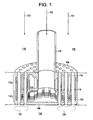
- FIG. 1 illustrates a perspective, partially cut-away view of an exemplary embodiment of a portion of a PDI injector nozzle 100 (injector).
- the injector 100 includes a body member 102 having an upstream wall 104 and a downstream wall 106.
- a baffle member 108 is disposed in the body member 102, and defines an upstream chamber 110 and a downstream chamber 112.
- a plurality of mixing tubes 114 is disposed in the body member 102.
- the mixing tubes 114 include inlets 116 communicative between the upstream chamber 110 and an inner surface of the mixing tubes 114.
- air flows along a path indicated by the arrow 101 through a shroud 118.
- the air enters the mixing tubes 114 via apertures in the upstream wall 104.
- a fuel such as, for example, hydrogen gas or a mixture of gasses flows along a path indicated by the arrow 103 through a fuel cavity 120.
- the fuel enters the body member 102 in the downstream chamber 112.
- the fuel flows radialy outward from the center of the down stream chamber 112 and into the upstream chamber 110.
- the fuel enters the inlets 116 and flows into the mixing tubes 114.
- the fuel and air mix in the mixing tubes 114 and are emitted as a fuel-air mixture from the mixing tubes into a combustor portion 122 of a turbine engine.
- the fuel-air mixture combusts in the flame regions 124 of the combustor portion 122.
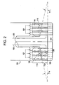
- FIG. 2 illustrates a side cut-away view of a portion of the injector 100, and will further illustrate the operation of the injector 100.
- the fuel flow is shown by the arrows 103.
- the fuel enters the downstream chamber 112 along a path parallel to the center axis 201 of the injector 100.
- the fuel flows radialy outward from the center axis 201.
- the fuel flows into the upstream chamber 110 after passing an outer lip of the baffle member 108.
- the fuel flows through the upstream chamber 110, enters the inlets 116, and flows into the mixing tubes 114.
- the fuel-air mix is created in the mixing tubes 114, downstream from the inlets 116.
- the fuel is cooler than the air.
- the flow of the fuel around the surface of the mixing tubes 114 in the downstream chamber 112 cools the mixing tubes 114 and helps to prevent the ignition or sustained burning of the fuel-air mixture inside the mixing tubes 114.
- the velocity of the fuel flow is maintained above a threshold level.
- the surface area of the downstream wall 106 increases. Since the velocity of the fuel flow is influenced by the volume of the downstream chamber 112, the baffle member 108 that is disposed at an oblique angle to the down stream wall 106, the volume of the chamber increases as the fuel flow approaches the outer diameter of the downstream chamber 112-reducing the velocity of the fuel flow.
- the baffle member 108 is shown at an angle ( ⁇ ) relative to the downstream wall 106.
- the angle ( ⁇ ) of the baffle member 108 reduces the distance between the baffle member 108 and the downstream wall 106 (indicated by arrow 203) as the fuel flows radialy outward in the downstream chamber 112.
- the reduction of the distance 203 in proportion to the increase in the surface area of the downstream wall 106 allows the volume of the downstream chamber 112 to be maintained below a threshold volume.
- the angle ( ⁇ ) of the baffle member 108 may be geometrically calculated to effectively maintain the lower threshold velocity of the gas flow.
- the angle of the baffle member 108 also reduces the distance between the baffle member 108 and the upstream wall 104 as the fuel flows into the upstream chamber 110.
- the angle of the baffle member 108 helps to maintain a uniform pressure and velocity of the fuel flow in the upstream chamber 110.
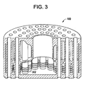
- FIG. 3 illustrates a perspective, partially cut-away view of a portion of the injector 100.
- the heat exchange between the fuel and the outer surface of the mixing tubes 114 may be improved by cooling features disposed on the outer surface of the mixing tubes 114.
- FIG. 3 shows an exemplary embodiment of cooling fins 302 connected to the mixing tubes 114.
- the cooling fins 302 increase the surface area of the outer surface of the mixing tubes 114 and improve the heat exchange between the fuel and the outer surface of the mixing tubes 114.
- the additional surface area, and/or a higher heat transfer coefficient effect the improvement in the heat exchange.
- FIG. 3 is an example of one embodiment of cooling features.
- Other embodiments may include, for example, a different number of cooling fins, dimples, ridges, fins at oblique angles, groves, channels, or other similar cooling features.
Landscapes
- Engineering & Computer Science (AREA)
- Chemical & Material Sciences (AREA)
- Combustion & Propulsion (AREA)
- Mechanical Engineering (AREA)
- General Engineering & Computer Science (AREA)
- Fuel-Injection Apparatus (AREA)
- Gas Burners (AREA)
Applications Claiming Priority (1)
| Application Number | Priority Date | Filing Date | Title |
|---|---|---|---|
| US12/417,896 US8157189B2 (en) | 2009-04-03 | 2009-04-03 | Premixing direct injector |
Publications (3)
| Publication Number | Publication Date |
|---|---|
| EP2239506A2 EP2239506A2 (en) | 2010-10-13 |
| EP2239506A3 EP2239506A3 (en) | 2012-08-15 |
| EP2239506B1 true EP2239506B1 (en) | 2015-07-22 |
Family
ID=42269514
Family Applications (1)
| Application Number | Title | Priority Date | Filing Date |
|---|---|---|---|
| EP10152193.8A Active EP2239506B1 (en) | 2009-04-03 | 2010-01-29 | Premixing direct injector |
Country Status (4)
| Country | Link |
|---|---|
| US (1) | US8157189B2 (enExample) |
| EP (1) | EP2239506B1 (enExample) |
| JP (1) | JP5508879B2 (enExample) |
| CN (1) | CN101858605B (enExample) |
Families Citing this family (52)
| Publication number | Priority date | Publication date | Assignee | Title |
|---|---|---|---|---|
| US9140454B2 (en) | 2009-01-23 | 2015-09-22 | General Electric Company | Bundled multi-tube nozzle for a turbomachine |
| EP2264370B1 (de) * | 2009-06-16 | 2012-10-10 | Siemens Aktiengesellschaft | Brenneranordnung für eine Verfeuerungsanlage zum Verfeuern fluidischer Brennstoffe und Verfahren zum Betrieb einer solchen Brenneranordnung |
| US8794545B2 (en) * | 2009-09-25 | 2014-08-05 | General Electric Company | Internal baffling for fuel injector |
| US8276385B2 (en) * | 2009-10-08 | 2012-10-02 | General Electric Company | Staged multi-tube premixing injector |
| US8603203B2 (en) * | 2010-04-12 | 2013-12-10 | Samsung Sdi Co., Ltd. | Burner nozzle assembly and fuel reformer having the same |
| EP2402655A1 (de) * | 2010-07-02 | 2012-01-04 | Siemens Aktiengesellschaft | Brennermodul |
| US8800289B2 (en) | 2010-09-08 | 2014-08-12 | General Electric Company | Apparatus and method for mixing fuel in a gas turbine nozzle |
| US9010083B2 (en) | 2011-02-03 | 2015-04-21 | General Electric Company | Apparatus for mixing fuel in a gas turbine |
| US8955327B2 (en) * | 2011-08-16 | 2015-02-17 | General Electric Company | Micromixer heat shield |
| US9506654B2 (en) | 2011-08-19 | 2016-11-29 | General Electric Company | System and method for reducing combustion dynamics in a combustor |
| US8984887B2 (en) | 2011-09-25 | 2015-03-24 | General Electric Company | Combustor and method for supplying fuel to a combustor |
| US8801428B2 (en) | 2011-10-04 | 2014-08-12 | General Electric Company | Combustor and method for supplying fuel to a combustor |
| US8550809B2 (en) | 2011-10-20 | 2013-10-08 | General Electric Company | Combustor and method for conditioning flow through a combustor |
| US9188335B2 (en) | 2011-10-26 | 2015-11-17 | General Electric Company | System and method for reducing combustion dynamics and NOx in a combustor |
| US8894407B2 (en) | 2011-11-11 | 2014-11-25 | General Electric Company | Combustor and method for supplying fuel to a combustor |
| US9033699B2 (en) | 2011-11-11 | 2015-05-19 | General Electric Company | Combustor |
| US20130122436A1 (en) * | 2011-11-11 | 2013-05-16 | General Electric Company | Combustor and method for supplying fuel to a combustor |
| US9004912B2 (en) | 2011-11-11 | 2015-04-14 | General Electric Company | Combustor and method for supplying fuel to a combustor |
| US8438851B1 (en) * | 2012-01-03 | 2013-05-14 | General Electric Company | Combustor assembly for use in a turbine engine and methods of assembling same |
| US9322557B2 (en) * | 2012-01-05 | 2016-04-26 | General Electric Company | Combustor and method for distributing fuel in the combustor |
| US20130192234A1 (en) * | 2012-01-26 | 2013-08-01 | General Electric Company | Bundled multi-tube nozzle assembly |
| US9341376B2 (en) | 2012-02-20 | 2016-05-17 | General Electric Company | Combustor and method for supplying fuel to a combustor |
| US9052112B2 (en) | 2012-02-27 | 2015-06-09 | General Electric Company | Combustor and method for purging a combustor |
| US8511086B1 (en) | 2012-03-01 | 2013-08-20 | General Electric Company | System and method for reducing combustion dynamics in a combustor |
| US9121612B2 (en) | 2012-03-01 | 2015-09-01 | General Electric Company | System and method for reducing combustion dynamics in a combustor |
| US9163839B2 (en) * | 2012-03-19 | 2015-10-20 | General Electric Company | Micromixer combustion head end assembly |
| US8701419B2 (en) * | 2012-05-10 | 2014-04-22 | General Electric Company | Multi-tube fuel nozzle with mixing features |
| US9709277B2 (en) * | 2012-05-15 | 2017-07-18 | General Electric Company | Fuel plenum premixing tube with surface treatment |
| US9261279B2 (en) * | 2012-05-25 | 2016-02-16 | General Electric Company | Liquid cartridge with passively fueled premixed air blast circuit for gas operation |
| US20130318976A1 (en) * | 2012-05-29 | 2013-12-05 | General Electric Company | Turbomachine combustor nozzle and method of forming the same |
| US9267690B2 (en) * | 2012-05-29 | 2016-02-23 | General Electric Company | Turbomachine combustor nozzle including a monolithic nozzle component and method of forming the same |
| US20140000269A1 (en) * | 2012-06-29 | 2014-01-02 | General Electric Company | Combustion nozzle and an associated method thereof |
| US9249734B2 (en) | 2012-07-10 | 2016-02-02 | General Electric Company | Combustor |
| US8904798B2 (en) | 2012-07-31 | 2014-12-09 | General Electric Company | Combustor |
| US9677766B2 (en) * | 2012-11-28 | 2017-06-13 | General Electric Company | Fuel nozzle for use in a turbine engine and method of assembly |
| US9291103B2 (en) | 2012-12-05 | 2016-03-22 | General Electric Company | Fuel nozzle for a combustor of a gas turbine engine |
| US9353950B2 (en) | 2012-12-10 | 2016-05-31 | General Electric Company | System for reducing combustion dynamics and NOx in a combustor |
| US9151503B2 (en) * | 2013-01-04 | 2015-10-06 | General Electric Company | Coaxial fuel supply for a micromixer |
| US20140270731A1 (en) * | 2013-03-12 | 2014-09-18 | Applied Materials, Inc. | Thermal management apparatus for solid state light source arrays |
| US9273868B2 (en) | 2013-08-06 | 2016-03-01 | General Electric Company | System for supporting bundled tube segments within a combustor |
| KR101838822B1 (ko) * | 2013-10-18 | 2018-03-14 | 미츠비시 쥬고교 가부시키가이샤 | 연료 분사기 |
| US9423135B2 (en) * | 2013-11-21 | 2016-08-23 | General Electric Company | Combustor having mixing tube bundle with baffle arrangement for directing fuel |
| US9518742B2 (en) | 2013-12-02 | 2016-12-13 | General Electric Company | Premixer assembly for mixing air and fuel for combustion |
| US10087844B2 (en) * | 2015-11-18 | 2018-10-02 | General Electric Company | Bundled tube fuel nozzle assembly with liquid fuel capability |
| US10145561B2 (en) | 2016-09-06 | 2018-12-04 | General Electric Company | Fuel nozzle assembly with resonator |
| JP6822894B2 (ja) | 2017-04-28 | 2021-01-27 | 三菱パワー株式会社 | 燃料噴射器及びガスタービン |
| US11701625B2 (en) | 2021-05-05 | 2023-07-18 | Gideon Vandegrift | Multiple-Venturi nozzle, system, method of manufacture and method of use |
| US12010958B2 (en) | 2021-05-05 | 2024-06-18 | Gideon Vandegrift | High flow Venturi nozzle, system, method of manufacture and method of use |
| CN113432121B (zh) * | 2021-06-09 | 2022-06-21 | 西安交通大学 | 一种异径环肋水冷型表面燃烧燃气装置 |
| CN115435338B (zh) * | 2022-11-09 | 2023-01-03 | 中国空气动力研究与发展中心超高速空气动力研究所 | 一种采用混合喷嘴的大流量燃烧加热喷注器 |
| US11867400B1 (en) * | 2023-02-02 | 2024-01-09 | Pratt & Whitney Canada Corp. | Combustor with fuel plenum with mixing passages having baffles |
| KR102932015B1 (ko) | 2024-01-25 | 2026-03-03 | 두산에너빌리티 주식회사 | 연소기용 노즐, 연소기, 및 이를 포함하는 가스 터빈 |
Family Cites Families (13)
| Publication number | Priority date | Publication date | Assignee | Title |
|---|---|---|---|---|
| US4100733A (en) * | 1976-10-04 | 1978-07-18 | United Technologies Corporation | Premix combustor |
| US4966001A (en) * | 1987-10-23 | 1990-10-30 | General Electric Company | Multiple venturi tube gas fuel injector for catalytic combustor |
| US5000004A (en) * | 1988-08-16 | 1991-03-19 | Kabushiki Kaisha Toshiba | Gas turbine combustor |
| GB9019188D0 (en) * | 1990-09-03 | 1990-10-17 | Turbotak Inc | Improved spray nozzle design |
| US5263325A (en) * | 1991-12-16 | 1993-11-23 | United Technologies Corporation | Low NOx combustion |
| CN2199457Y (zh) * | 1994-08-26 | 1995-05-31 | 胡俊达 | 燃气灶燃气空气自动混合器 |
| US5904477A (en) * | 1995-10-05 | 1999-05-18 | Shell Oil Company | Burner for partial oxidation of a hydrocarbon-containing fuel |
| US6267585B1 (en) * | 1995-12-19 | 2001-07-31 | Daimlerchrysler Aerospace Airbus Gmbh | Method and combustor for combusting hydrogen |
| US6427447B1 (en) * | 2001-02-06 | 2002-08-06 | United Technologies Corporation | Bulkhead for dual fuel industrial and aeroengine gas turbines |
| CN2551875Y (zh) * | 2002-04-01 | 2003-05-21 | 杜子君 | 防风型高效节能燃气燃烧器 |
| US8112999B2 (en) * | 2008-08-05 | 2012-02-14 | General Electric Company | Turbomachine injection nozzle including a coolant delivery system |
| US9140454B2 (en) * | 2009-01-23 | 2015-09-22 | General Electric Company | Bundled multi-tube nozzle for a turbomachine |
| US8539773B2 (en) * | 2009-02-04 | 2013-09-24 | General Electric Company | Premixed direct injection nozzle for highly reactive fuels |
-
2009
- 2009-04-03 US US12/417,896 patent/US8157189B2/en active Active
-
2010
- 2010-01-29 EP EP10152193.8A patent/EP2239506B1/en active Active
- 2010-02-01 JP JP2010019850A patent/JP5508879B2/ja active Active
- 2010-02-03 CN CN201010119082.3A patent/CN101858605B/zh active Active
Also Published As
| Publication number | Publication date |
|---|---|
| CN101858605B (zh) | 2014-03-05 |
| US20100252652A1 (en) | 2010-10-07 |
| US8157189B2 (en) | 2012-04-17 |
| EP2239506A3 (en) | 2012-08-15 |
| JP5508879B2 (ja) | 2014-06-04 |
| JP2010243146A (ja) | 2010-10-28 |
| CN101858605A (zh) | 2010-10-13 |
| EP2239506A2 (en) | 2010-10-13 |
Similar Documents
| Publication | Publication Date | Title |
|---|---|---|
| EP2239506B1 (en) | Premixing direct injector | |
| JP5583368B2 (ja) | 予混合直接噴射ノズル | |
| US7065972B2 (en) | Fuel-air mixing apparatus for reducing gas turbine combustor exhaust emissions | |
| US8276385B2 (en) | Staged multi-tube premixing injector | |
| US8117845B2 (en) | Systems to facilitate reducing flashback/flame holding in combustion systems | |
| EP2405201B1 (en) | Injection nozzle for a turbomachine | |
| EP2912381B1 (en) | Sequential combustion with dilution gas mixer | |
| US6374615B1 (en) | Low cost, low emissions natural gas combustor | |
| EP2525149B1 (en) | Gas turbine combustor | |
| CN103185353B (zh) | 用于涡轮发动机中的燃烧器组件及其组装方法 | |
| JP6196868B2 (ja) | 燃料ノズルとその組立方法 | |
| CN100552300C (zh) | 用于燃烧器的同心的固定稀释及可变的旁路空气喷射 | |
| US8256226B2 (en) | Radial lean direct injection burner | |
| EP2754963A1 (en) | Gas turbine combustor | |
| JP2011169573A (ja) | 多管式予混合噴射器 | |
| CN101294715A (zh) | 燃烧装置及烧嘴的燃烧方法 | |
| CN109654537B (zh) | 一种中心燃料喷嘴 | |
| JP2016017740A (ja) | ミキサを備えた2段燃焼器配列 | |
| KR20160030051A (ko) | 가스 터빈의 연소기를 위한 희석 가스 또는 공기 혼합기 | |
| CN105121962B (zh) | 具有稀释气体的连续燃烧 | |
| JP5610446B2 (ja) | ガスタービン燃焼器 |
Legal Events
| Date | Code | Title | Description |
|---|---|---|---|
| PUAI | Public reference made under article 153(3) epc to a published international application that has entered the european phase |
Free format text: ORIGINAL CODE: 0009012 |
|
| AK | Designated contracting states |
Kind code of ref document: A2 Designated state(s): AT BE BG CH CY CZ DE DK EE ES FI FR GB GR HR HU IE IS IT LI LT LU LV MC MK MT NL NO PL PT RO SE SI SK SM TR |
|
| AX | Request for extension of the european patent |
Extension state: AL BA RS |
|
| PUAL | Search report despatched |
Free format text: ORIGINAL CODE: 0009013 |
|
| AK | Designated contracting states |
Kind code of ref document: A3 Designated state(s): AT BE BG CH CY CZ DE DK EE ES FI FR GB GR HR HU IE IS IT LI LT LU LV MC MK MT NL NO PL PT RO SE SI SK SM TR |
|
| AX | Request for extension of the european patent |
Extension state: AL BA RS |
|
| RIC1 | Information provided on ipc code assigned before grant |
Ipc: F23R 3/28 20060101AFI20120706BHEP Ipc: F23R 3/10 20060101ALI20120706BHEP Ipc: F23D 14/62 20060101ALI20120706BHEP |
|
| 17P | Request for examination filed |
Effective date: 20130215 |
|
| GRAP | Despatch of communication of intention to grant a patent |
Free format text: ORIGINAL CODE: EPIDOSNIGR1 |
|
| INTG | Intention to grant announced |
Effective date: 20150305 |
|
| GRAS | Grant fee paid |
Free format text: ORIGINAL CODE: EPIDOSNIGR3 |
|
| GRAA | (expected) grant |
Free format text: ORIGINAL CODE: 0009210 |
|
| AK | Designated contracting states |
Kind code of ref document: B1 Designated state(s): AT BE BG CH CY CZ DE DK EE ES FI FR GB GR HR HU IE IS IT LI LT LU LV MC MK MT NL NO PL PT RO SE SI SK SM TR |
|
| REG | Reference to a national code |
Ref country code: GB Ref legal event code: FG4D |
|
| REG | Reference to a national code |
Ref country code: CH Ref legal event code: EP |
|
| REG | Reference to a national code |
Ref country code: IE Ref legal event code: FG4D |
|
| REG | Reference to a national code |
Ref country code: AT Ref legal event code: REF Ref document number: 738136 Country of ref document: AT Kind code of ref document: T Effective date: 20150815 |
|
| REG | Reference to a national code |
Ref country code: DE Ref legal event code: R096 Ref document number: 602010025999 Country of ref document: DE |
|
| REG | Reference to a national code |
Ref country code: AT Ref legal event code: MK05 Ref document number: 738136 Country of ref document: AT Kind code of ref document: T Effective date: 20150722 |
|
| REG | Reference to a national code |
Ref country code: LT Ref legal event code: MG4D |
|
| REG | Reference to a national code |
Ref country code: NL Ref legal event code: MP Effective date: 20150722 |
|
| PG25 | Lapsed in a contracting state [announced via postgrant information from national office to epo] |
Ref country code: NO Free format text: LAPSE BECAUSE OF FAILURE TO SUBMIT A TRANSLATION OF THE DESCRIPTION OR TO PAY THE FEE WITHIN THE PRESCRIBED TIME-LIMIT Effective date: 20151022 Ref country code: GR Free format text: LAPSE BECAUSE OF FAILURE TO SUBMIT A TRANSLATION OF THE DESCRIPTION OR TO PAY THE FEE WITHIN THE PRESCRIBED TIME-LIMIT Effective date: 20151023 Ref country code: FI Free format text: LAPSE BECAUSE OF FAILURE TO SUBMIT A TRANSLATION OF THE DESCRIPTION OR TO PAY THE FEE WITHIN THE PRESCRIBED TIME-LIMIT Effective date: 20150722 Ref country code: LT Free format text: LAPSE BECAUSE OF FAILURE TO SUBMIT A TRANSLATION OF THE DESCRIPTION OR TO PAY THE FEE WITHIN THE PRESCRIBED TIME-LIMIT Effective date: 20150722 Ref country code: LV Free format text: LAPSE BECAUSE OF FAILURE TO SUBMIT A TRANSLATION OF THE DESCRIPTION OR TO PAY THE FEE WITHIN THE PRESCRIBED TIME-LIMIT Effective date: 20150722 |
|
| PG25 | Lapsed in a contracting state [announced via postgrant information from national office to epo] |
Ref country code: PT Free format text: LAPSE BECAUSE OF FAILURE TO SUBMIT A TRANSLATION OF THE DESCRIPTION OR TO PAY THE FEE WITHIN THE PRESCRIBED TIME-LIMIT Effective date: 20151123 Ref country code: IS Free format text: LAPSE BECAUSE OF FAILURE TO SUBMIT A TRANSLATION OF THE DESCRIPTION OR TO PAY THE FEE WITHIN THE PRESCRIBED TIME-LIMIT Effective date: 20151122 Ref country code: SE Free format text: LAPSE BECAUSE OF FAILURE TO SUBMIT A TRANSLATION OF THE DESCRIPTION OR TO PAY THE FEE WITHIN THE PRESCRIBED TIME-LIMIT Effective date: 20150722 Ref country code: PL Free format text: LAPSE BECAUSE OF FAILURE TO SUBMIT A TRANSLATION OF THE DESCRIPTION OR TO PAY THE FEE WITHIN THE PRESCRIBED TIME-LIMIT Effective date: 20150722 Ref country code: AT Free format text: LAPSE BECAUSE OF FAILURE TO SUBMIT A TRANSLATION OF THE DESCRIPTION OR TO PAY THE FEE WITHIN THE PRESCRIBED TIME-LIMIT Effective date: 20150722 Ref country code: HR Free format text: LAPSE BECAUSE OF FAILURE TO SUBMIT A TRANSLATION OF THE DESCRIPTION OR TO PAY THE FEE WITHIN THE PRESCRIBED TIME-LIMIT Effective date: 20150722 Ref country code: ES Free format text: LAPSE BECAUSE OF FAILURE TO SUBMIT A TRANSLATION OF THE DESCRIPTION OR TO PAY THE FEE WITHIN THE PRESCRIBED TIME-LIMIT Effective date: 20150722 |
|
| REG | Reference to a national code |
Ref country code: DE Ref legal event code: R097 Ref document number: 602010025999 Country of ref document: DE |
|
| PG25 | Lapsed in a contracting state [announced via postgrant information from national office to epo] |
Ref country code: EE Free format text: LAPSE BECAUSE OF FAILURE TO SUBMIT A TRANSLATION OF THE DESCRIPTION OR TO PAY THE FEE WITHIN THE PRESCRIBED TIME-LIMIT Effective date: 20150722 Ref country code: SK Free format text: LAPSE BECAUSE OF FAILURE TO SUBMIT A TRANSLATION OF THE DESCRIPTION OR TO PAY THE FEE WITHIN THE PRESCRIBED TIME-LIMIT Effective date: 20150722 Ref country code: IT Free format text: LAPSE BECAUSE OF FAILURE TO SUBMIT A TRANSLATION OF THE DESCRIPTION OR TO PAY THE FEE WITHIN THE PRESCRIBED TIME-LIMIT Effective date: 20150722 Ref country code: DK Free format text: LAPSE BECAUSE OF FAILURE TO SUBMIT A TRANSLATION OF THE DESCRIPTION OR TO PAY THE FEE WITHIN THE PRESCRIBED TIME-LIMIT Effective date: 20150722 Ref country code: CZ Free format text: LAPSE BECAUSE OF FAILURE TO SUBMIT A TRANSLATION OF THE DESCRIPTION OR TO PAY THE FEE WITHIN THE PRESCRIBED TIME-LIMIT Effective date: 20150722 |
|
| PLBE | No opposition filed within time limit |
Free format text: ORIGINAL CODE: 0009261 |
|
| STAA | Information on the status of an ep patent application or granted ep patent |
Free format text: STATUS: NO OPPOSITION FILED WITHIN TIME LIMIT |
|
| PG25 | Lapsed in a contracting state [announced via postgrant information from national office to epo] |
Ref country code: BE Free format text: LAPSE BECAUSE OF NON-PAYMENT OF DUE FEES Effective date: 20160131 Ref country code: RO Free format text: LAPSE BECAUSE OF FAILURE TO SUBMIT A TRANSLATION OF THE DESCRIPTION OR TO PAY THE FEE WITHIN THE PRESCRIBED TIME-LIMIT Effective date: 20150722 |
|
| 26N | No opposition filed |
Effective date: 20160425 |
|
| PG25 | Lapsed in a contracting state [announced via postgrant information from national office to epo] |
Ref country code: SI Free format text: LAPSE BECAUSE OF FAILURE TO SUBMIT A TRANSLATION OF THE DESCRIPTION OR TO PAY THE FEE WITHIN THE PRESCRIBED TIME-LIMIT Effective date: 20150722 Ref country code: LU Free format text: LAPSE BECAUSE OF FAILURE TO SUBMIT A TRANSLATION OF THE DESCRIPTION OR TO PAY THE FEE WITHIN THE PRESCRIBED TIME-LIMIT Effective date: 20160129 |
|
| REG | Reference to a national code |
Ref country code: CH Ref legal event code: PL |
|
| GBPC | Gb: european patent ceased through non-payment of renewal fee |
Effective date: 20160129 |
|
| PG25 | Lapsed in a contracting state [announced via postgrant information from national office to epo] |
Ref country code: MC Free format text: LAPSE BECAUSE OF FAILURE TO SUBMIT A TRANSLATION OF THE DESCRIPTION OR TO PAY THE FEE WITHIN THE PRESCRIBED TIME-LIMIT Effective date: 20150722 |
|
| REG | Reference to a national code |
Ref country code: FR Ref legal event code: ST Effective date: 20160930 |
|
| PG25 | Lapsed in a contracting state [announced via postgrant information from national office to epo] |
Ref country code: CH Free format text: LAPSE BECAUSE OF NON-PAYMENT OF DUE FEES Effective date: 20160131 Ref country code: LI Free format text: LAPSE BECAUSE OF NON-PAYMENT OF DUE FEES Effective date: 20160131 Ref country code: GB Free format text: LAPSE BECAUSE OF NON-PAYMENT OF DUE FEES Effective date: 20160129 |
|
| REG | Reference to a national code |
Ref country code: IE Ref legal event code: MM4A |
|
| PG25 | Lapsed in a contracting state [announced via postgrant information from national office to epo] |
Ref country code: FR Free format text: LAPSE BECAUSE OF NON-PAYMENT OF DUE FEES Effective date: 20160201 |
|
| PG25 | Lapsed in a contracting state [announced via postgrant information from national office to epo] |
Ref country code: BE Free format text: LAPSE BECAUSE OF FAILURE TO SUBMIT A TRANSLATION OF THE DESCRIPTION OR TO PAY THE FEE WITHIN THE PRESCRIBED TIME-LIMIT Effective date: 20150722 |
|
| PG25 | Lapsed in a contracting state [announced via postgrant information from national office to epo] |
Ref country code: IE Free format text: LAPSE BECAUSE OF NON-PAYMENT OF DUE FEES Effective date: 20160129 |
|
| PG25 | Lapsed in a contracting state [announced via postgrant information from national office to epo] |
Ref country code: NL Free format text: LAPSE BECAUSE OF FAILURE TO SUBMIT A TRANSLATION OF THE DESCRIPTION OR TO PAY THE FEE WITHIN THE PRESCRIBED TIME-LIMIT Effective date: 20150722 |
|
| PG25 | Lapsed in a contracting state [announced via postgrant information from national office to epo] |
Ref country code: MT Free format text: LAPSE BECAUSE OF FAILURE TO SUBMIT A TRANSLATION OF THE DESCRIPTION OR TO PAY THE FEE WITHIN THE PRESCRIBED TIME-LIMIT Effective date: 20150722 |
|
| PG25 | Lapsed in a contracting state [announced via postgrant information from national office to epo] |
Ref country code: HU Free format text: LAPSE BECAUSE OF FAILURE TO SUBMIT A TRANSLATION OF THE DESCRIPTION OR TO PAY THE FEE WITHIN THE PRESCRIBED TIME-LIMIT; INVALID AB INITIO Effective date: 20100129 Ref country code: CY Free format text: LAPSE BECAUSE OF FAILURE TO SUBMIT A TRANSLATION OF THE DESCRIPTION OR TO PAY THE FEE WITHIN THE PRESCRIBED TIME-LIMIT Effective date: 20150722 Ref country code: SM Free format text: LAPSE BECAUSE OF FAILURE TO SUBMIT A TRANSLATION OF THE DESCRIPTION OR TO PAY THE FEE WITHIN THE PRESCRIBED TIME-LIMIT Effective date: 20150722 |
|
| PG25 | Lapsed in a contracting state [announced via postgrant information from national office to epo] |
Ref country code: MK Free format text: LAPSE BECAUSE OF FAILURE TO SUBMIT A TRANSLATION OF THE DESCRIPTION OR TO PAY THE FEE WITHIN THE PRESCRIBED TIME-LIMIT Effective date: 20150722 Ref country code: TR Free format text: LAPSE BECAUSE OF FAILURE TO SUBMIT A TRANSLATION OF THE DESCRIPTION OR TO PAY THE FEE WITHIN THE PRESCRIBED TIME-LIMIT Effective date: 20150722 Ref country code: MT Free format text: LAPSE BECAUSE OF FAILURE TO SUBMIT A TRANSLATION OF THE DESCRIPTION OR TO PAY THE FEE WITHIN THE PRESCRIBED TIME-LIMIT Effective date: 20160131 |
|
| PG25 | Lapsed in a contracting state [announced via postgrant information from national office to epo] |
Ref country code: BG Free format text: LAPSE BECAUSE OF FAILURE TO SUBMIT A TRANSLATION OF THE DESCRIPTION OR TO PAY THE FEE WITHIN THE PRESCRIBED TIME-LIMIT Effective date: 20150722 |
|
| REG | Reference to a national code |
Ref country code: DE Ref legal event code: R081 Ref document number: 602010025999 Country of ref document: DE Owner name: GENERAL ELECTRIC TECHNOLOGY GMBH, CH Free format text: FORMER OWNER: GENERAL ELECTRIC CO., SCHENECTADY, N.Y., US |
|
| PGFP | Annual fee paid to national office [announced via postgrant information from national office to epo] |
Ref country code: DE Payment date: 20251217 Year of fee payment: 17 |