EP2239434A1 - Abgasbehandlungseinrichtung und zugehöriges Herstellungsverfahren - Google Patents
Abgasbehandlungseinrichtung und zugehöriges Herstellungsverfahren Download PDFInfo
- Publication number
- EP2239434A1 EP2239434A1 EP10155413A EP10155413A EP2239434A1 EP 2239434 A1 EP2239434 A1 EP 2239434A1 EP 10155413 A EP10155413 A EP 10155413A EP 10155413 A EP10155413 A EP 10155413A EP 2239434 A1 EP2239434 A1 EP 2239434A1
- Authority
- EP
- European Patent Office
- Prior art keywords
- hood
- connecting piece
- treatment device
- connection
- exhaust
- Prior art date
- Legal status (The legal status is an assumption and is not a legal conclusion. Google has not performed a legal analysis and makes no representation as to the accuracy of the status listed.)
- Granted
Links
Images


Classifications
-
- F—MECHANICAL ENGINEERING; LIGHTING; HEATING; WEAPONS; BLASTING
- F01—MACHINES OR ENGINES IN GENERAL; ENGINE PLANTS IN GENERAL; STEAM ENGINES
- F01N—GAS-FLOW SILENCERS OR EXHAUST APPARATUS FOR MACHINES OR ENGINES IN GENERAL; GAS-FLOW SILENCERS OR EXHAUST APPARATUS FOR INTERNAL-COMBUSTION ENGINES
- F01N13/00—Exhaust or silencing apparatus characterised by constructional features
- F01N13/18—Construction facilitating manufacture, assembly, or disassembly
- F01N13/1872—Construction facilitating manufacture, assembly, or disassembly the assembly using stamp-formed parts or otherwise deformed sheet-metal
-
- F—MECHANICAL ENGINEERING; LIGHTING; HEATING; WEAPONS; BLASTING
- F01—MACHINES OR ENGINES IN GENERAL; ENGINE PLANTS IN GENERAL; STEAM ENGINES
- F01N—GAS-FLOW SILENCERS OR EXHAUST APPARATUS FOR MACHINES OR ENGINES IN GENERAL; GAS-FLOW SILENCERS OR EXHAUST APPARATUS FOR INTERNAL-COMBUSTION ENGINES
- F01N13/00—Exhaust or silencing apparatus characterised by constructional features
- F01N13/18—Construction facilitating manufacture, assembly, or disassembly
- F01N13/1838—Construction facilitating manufacture, assembly, or disassembly characterised by the type of connection between parts of exhaust or silencing apparatus, e.g. between housing and tubes, between tubes and baffles
-
- F—MECHANICAL ENGINEERING; LIGHTING; HEATING; WEAPONS; BLASTING
- F01—MACHINES OR ENGINES IN GENERAL; ENGINE PLANTS IN GENERAL; STEAM ENGINES
- F01N—GAS-FLOW SILENCERS OR EXHAUST APPARATUS FOR MACHINES OR ENGINES IN GENERAL; GAS-FLOW SILENCERS OR EXHAUST APPARATUS FOR INTERNAL-COMBUSTION ENGINES
- F01N13/00—Exhaust or silencing apparatus characterised by constructional features
- F01N13/18—Construction facilitating manufacture, assembly, or disassembly
- F01N13/1888—Construction facilitating manufacture, assembly, or disassembly the housing of the assembly consisting of two or more parts, e.g. two half-shells
-
- F—MECHANICAL ENGINEERING; LIGHTING; HEATING; WEAPONS; BLASTING
- F01—MACHINES OR ENGINES IN GENERAL; ENGINE PLANTS IN GENERAL; STEAM ENGINES
- F01N—GAS-FLOW SILENCERS OR EXHAUST APPARATUS FOR MACHINES OR ENGINES IN GENERAL; GAS-FLOW SILENCERS OR EXHAUST APPARATUS FOR INTERNAL-COMBUSTION ENGINES
- F01N13/00—Exhaust or silencing apparatus characterised by constructional features
- F01N13/18—Construction facilitating manufacture, assembly, or disassembly
- F01N13/1888—Construction facilitating manufacture, assembly, or disassembly the housing of the assembly consisting of two or more parts, e.g. two half-shells
- F01N13/1894—Construction facilitating manufacture, assembly, or disassembly the housing of the assembly consisting of two or more parts, e.g. two half-shells the parts being assembled in longitudinal direction
-
- F—MECHANICAL ENGINEERING; LIGHTING; HEATING; WEAPONS; BLASTING
- F01—MACHINES OR ENGINES IN GENERAL; ENGINE PLANTS IN GENERAL; STEAM ENGINES
- F01N—GAS-FLOW SILENCERS OR EXHAUST APPARATUS FOR MACHINES OR ENGINES IN GENERAL; GAS-FLOW SILENCERS OR EXHAUST APPARATUS FOR INTERNAL-COMBUSTION ENGINES
- F01N3/00—Exhaust or silencing apparatus having means for purifying, rendering innocuous, or otherwise treating exhaust
- F01N3/08—Exhaust or silencing apparatus having means for purifying, rendering innocuous, or otherwise treating exhaust for rendering innocuous
- F01N3/10—Exhaust or silencing apparatus having means for purifying, rendering innocuous, or otherwise treating exhaust for rendering innocuous by thermal or catalytic conversion of noxious components of exhaust
- F01N3/24—Exhaust or silencing apparatus having means for purifying, rendering innocuous, or otherwise treating exhaust for rendering innocuous by thermal or catalytic conversion of noxious components of exhaust characterised by constructional aspects of converting apparatus
- F01N3/28—Construction of catalytic reactors
-
- F—MECHANICAL ENGINEERING; LIGHTING; HEATING; WEAPONS; BLASTING
- F01—MACHINES OR ENGINES IN GENERAL; ENGINE PLANTS IN GENERAL; STEAM ENGINES
- F01N—GAS-FLOW SILENCERS OR EXHAUST APPARATUS FOR MACHINES OR ENGINES IN GENERAL; GAS-FLOW SILENCERS OR EXHAUST APPARATUS FOR INTERNAL-COMBUSTION ENGINES
- F01N13/00—Exhaust or silencing apparatus characterised by constructional features
- F01N13/18—Construction facilitating manufacture, assembly, or disassembly
-
- F—MECHANICAL ENGINEERING; LIGHTING; HEATING; WEAPONS; BLASTING
- F01—MACHINES OR ENGINES IN GENERAL; ENGINE PLANTS IN GENERAL; STEAM ENGINES
- F01N—GAS-FLOW SILENCERS OR EXHAUST APPARATUS FOR MACHINES OR ENGINES IN GENERAL; GAS-FLOW SILENCERS OR EXHAUST APPARATUS FOR INTERNAL-COMBUSTION ENGINES
- F01N2470/00—Structure or shape of exhaust gas passages, pipes or tubes
- F01N2470/06—Tubes being formed by assembly of stamped or otherwise deformed sheet-metal
-
- Y—GENERAL TAGGING OF NEW TECHNOLOGICAL DEVELOPMENTS; GENERAL TAGGING OF CROSS-SECTIONAL TECHNOLOGIES SPANNING OVER SEVERAL SECTIONS OF THE IPC; TECHNICAL SUBJECTS COVERED BY FORMER USPC CROSS-REFERENCE ART COLLECTIONS [XRACs] AND DIGESTS
- Y10—TECHNICAL SUBJECTS COVERED BY FORMER USPC
- Y10T—TECHNICAL SUBJECTS COVERED BY FORMER US CLASSIFICATION
- Y10T29/00—Metal working
- Y10T29/49—Method of mechanical manufacture
- Y10T29/49398—Muffler, manifold or exhaust pipe making
Definitions
- the present invention relates to a method for producing an exhaust gas treatment device for an exhaust system of an internal combustion engine.
- the present invention also relates to an exhaust gas treatment device for an exhaust system of an internal combustion engine.
- the present invention also relates to a kit for producing exhaust gas treatment devices.
- an exhaust gas treatment device used in motor vehicles, such.
- a particulate filter, a catalytic converter, a silencer or any combination thereof a housing, the circumference of a shell and the end each having a bottom. It is also customary to design at least one connection, namely an exhaust gas inlet or an exhaust gas outlet, on at least one of these end-side bottoms.
- the respective bottom is for example possible to design the respective bottom as a funnel, which is produced integrally with a corresponding connection piece, wherein a longitudinal center axis of the respective connection piece can be inclined relative to the longitudinal central axis of the housing in a corresponding manner.
- a corresponding number of appropriately configured funnels must be provided. This is associated with a considerable amount of tools and warehousing and logistics.
- the present invention is concerned with the problem of finding a way for an exhaust gas treatment device of the type mentioned above, which in particular enables a simplified production and thus a cheaper production.
- the present invention is based on the general idea to design at least one of the end bottoms of the housing as a hood, which is spherical or spherical segment-shaped.
- This particular hemispherical dome may e.g. be provided with a corresponding tool in a quasi arbitrary spatial position with a connection opening.
- a standardized connection piece can then be particularly easily recognized and connected to the hood.
- the proposed construction thus makes it possible to inexpensively adapt exhaust treatment devices to widely varying installation situations.
- the respective connecting piece can be formed at its end facing the hood complementary to the outer contour of the hood be.
- the connecting piece is equipped at its connection end with an annular, spherical segment-shaped collar which is shaped to match the spherical shape or spherical segment shape of the hood. Such a shape simplifies assembly and at the same time allows easy tolerance compensation.
- the hood facing the connecting end of the connecting piece can lie in a plane which is perpendicular to the longitudinal central axis of the connecting piece.
- the connection end of the connecting piece lies in a plane which is inclined relative to a normal plane running perpendicular to the longitudinal central axis of the connecting piece, for example by approximately 45 °.
- a collar can be integrally formed, by means of which the hood can be releasably attached via a clamp connection on the jacket.
- a kit according to the invention by means of which the exhaust gas treatment devices according to the invention can be produced or with the aid of which the method according to the invention for producing the exhaust gas treatment devices can be carried out, there is at least one type of jacket with which the respective jacket of the respective housing can be produced, at least a hood type without connection opening and suitable for the respective jacket type as well as at least one connection piece type suitable for the respective hood. It is clear that for different sized exhaust treatment devices as well different types of shells, hood types and connection types can be provided.
- Fig. 1 and 2 includes an exhaust treatment device 1, only partially shown, suitable for use in an exhaust system an internal combustion engine is suitable, a housing 2.
- This housing 2 has with respect to a longitudinal central axis 3 of the housing 2 a circumferentially closed circumferential jacket 4.
- the jacket 4 surrounds or surrounds at least one exhaust gas treatment element 5, wherein a bearing mat 6 can be arranged between the jacket 4 and the exhaust gas treatment element 5 in the usual way.
- the housing 2 has at its end, ie axially with respect to its longitudinal central axis 3, two end floors 7, of which in the Fig. 1 and 2 only one is recognizable.
- the internal combustion engine e.g. a diesel engine or gasoline engine
- the exhaust gas treatment device 1 can be designed, for example, as a particle filter device. Accordingly, the exhaust gas treatment element 5 is then a particle filter element. Alternatively, the exhaust gas treatment device 1 may also be a catalyst device, so that the exhaust gas treatment element 5 is then a catalyst element. Likewise, combined facilities are conceivable in which z. For example, an oxidation catalyst element is arranged upstream of a particle filter element.
- At least one of the floors 7, here the bottom 7 shown is designed as a hood 8, which has a spherical shape or spherical segment shape.
- the hood 8 is shaped as a hemisphere.
- the hemispherical hood 8 is grown on the jacket 4 in the region of its "equator".
- the hood 8 includes a connection opening 9, which passes through the hood 8 and in the finished state of the exhaust gas treatment device 1 can serve as an inlet port or as an exhaust port for exhaust gas.
- the connecting piece 10, 11 is mounted in the region of the respective connection opening 9 to the hood 8, so that said connection piece 10, 11 communicates through the respective connection opening 9 with the interior of the hood 8.
- the respective connecting piece 10, 11 in the finished state of the exhaust gas treatment device 1 forms an inlet connection or an outlet connection for exhaust gas.
- the respective connecting piece 10, 11 is welded to the hood 8.
- the respective connecting piece 10, 11 may be provided on a connecting end 12 facing the hood 8 with a collar 14 which protrudes outwards and is closed circumferentially in relation to a longitudinal central axis 13 of the respective connecting piece 10, 11.
- said collar 14 is complementary to the outer contour of the hood 8 in the region of the respective connection opening 9 enclosing opening edge 15 is formed. This results in a surface contact between collar 14 and opening edge 15, which simplifies the production of a gas-tight connection between the connecting piece 10, 11 and hood 8.
- the respective connecting piece 10, 11 can be configured in a straight line. Accordingly, it has a straight longitudinal central axis 13.
- the connecting piece 10 has a frusto-conical section, which easily converges with increasing distance from the hood 8. Further, in this embodiment, the terminal end 12 of the connecting piece 10 is designed so that it lies in a plane 16 which extends perpendicular to the longitudinal central axis 13 of the connecting piece 10.
- FIG. 2 shows Fig. 2 an embodiment in which the connecting piece 11 is cylindrically shaped and accordingly has a constant cross-section over its entire length. Further, in this embodiment, the terminal end 12 of the connecting piece 11 is located in a plane 17, which includes an angle 19 with a normal plane 18, that is inclined with respect to the normal plane 18. Said normal plane 18 extends perpendicular to the longitudinal central axis 13 of the connecting piece 11 Fig. 2 shown connecting piece 11 is thus tapered connection side. As a result, other angular ranges between the two longitudinal central axes 3, 13 of the respective connecting piece 10, 11 and the housing 2 or the shell 4 can be realized. For example, the chamfered connection piece 11 makes an angle of about 90 ° between the longitudinal central axis 3 of the housing 2 and the longitudinal central axis 13 of the connection piece 11.
- the Fig. 3a, 3b and 3c show in addition three embodiments of the hood 8.
- the in Fig. 3a shown hood 8 corresponds to those of Fig. 1 and 2
- the hood 8 is designed so that it can be releasably secured by means of a clamp, not shown, on the respective jacket 4.
- the hood 8 is provided on a jacket 4 facing side with respect to the longitudinal center axis 3 of the housing 2 circumferential collar 21.
- This can optionally be integrally formed on the hood 8.
- Fig. 3c is on the hood 8 also formed a circumferential annular groove 22 at the transition to the collar 21. In this annular groove 22, the respective clamp can engage to cooperate with the collar 21.
- the respective hood 8 usually contains only one of the connection openings 9 and not two as in the Fig. 3a to 3c shown. Besides that is the Fig. 3a to 3c removable, that the hood 8 at the jacket 4 facing Side may have a cylindrical portion 23 which simplifies the connection to the cylindrical shell 4.
- an inventive kit is in Fig. 4 globally denoted by 20.
- the exhaust treatment device 1 can be produced. It includes according to the Fig. 4a to 4c at least one type of jacket for producing the jacket 4 of the housing 2 and at least one hood type suitable for the respective jacket type for producing the hood 8 which fits the jacket 4.
- the kit 20 comprises at least one connecting piece type.
- the connecting piece 11 of Fig. 4a corresponds to the connecting piece 11 of Fig. 2 while the connecting piece 10 of the Fig. 4b the connecting piece 10 of Fig. 1 equivalent.
- the respective hood 8 is provided without the connection opening 9.
- the kit 20 may also have different types of shells for producing differently sized coats 4 and matching hood types. Also differently sized connection nozzle types can be present.
- Fig. 4 the spherical or spherical segment-shaped or hemispherical hood 8 produced or provided in the kit 20.
- the hood 8 can be used universally for any angle between the longitudinal central axis 3 of the housing 2 and the longitudinal central axis 13 of the still to be mounted connecting piece 10, 11.
- the hood 8 can be made, for example, from a flat sheet by deep drawing or by pressing.
- connection opening 9 is made at a suitable location of the hood 8, which in the state Fig. 5 is reproduced.
- the connection opening 9 can be produced, for example, by means of a suitable cutting tool or by means of a punching tool or by means of a laser welding method.
- connection piece 10 here the straight-line connection piece 10 accordingly Fig. 6 to be assembled.
- the respective connecting piece 10 is grown in the region of the connection opening 9 to the hood 8.
- the connecting piece 10 can be welded or soldered to the hood 8, for example.
- the in Fig. 6c state shown here corresponds to the illustration according to Fig. 1 ,
- the hood 8 is already in a state in which it still has no connection opening 9, grown on the jacket 4. It is clear that the hood 8 can also be attached to the casing 4 at a later time, in particular after the connection opening 9 has been produced and / or after the respective connection piece 10, 11 has been attached.
Landscapes
- Engineering & Computer Science (AREA)
- Chemical & Material Sciences (AREA)
- Combustion & Propulsion (AREA)
- Mechanical Engineering (AREA)
- General Engineering & Computer Science (AREA)
- Chemical Kinetics & Catalysis (AREA)
- Health & Medical Sciences (AREA)
- Toxicology (AREA)
- Exhaust Gas After Treatment (AREA)
Abstract
Description
- Die vorliegende Erfindung betrifft ein Verfahren zum Herstellen einer Abgasbehandlungseinrichtung für eine Abgasanlage einer Brennkraftmaschine. Die vorliegende Erfindung betrifft außerdem eine Abgasbehandlungseinrichtung für eine Abgasanlage einer Brennkraftmaschine. Ferner betrifft die vorliegende Erfindung auch einen Bausatz zum Herstellen von Abgasbehandlungseinrichtungen.
- Üblicherweise weist eine bei Kraftfahrzeugen zur Anwendung kommende Abgasbehandlungseinrichtung, wie z. Bsp. ein Partikelfilter, ein Katalysator, ein Schalldämpfer oder beliebige Kombinationen daraus, ein Gehäuse auf, das umfangsseitig einen Mantel und endseitig jeweils einen Boden aufweist. Üblich ist es ferner, zumindest einen Anschluss, nämlich einen Abgaseinlass bzw. einen Abgasauslass, an zumindest einem dieser endseitigen Böden auszubilden.
- Für unterschiedliche Einbausituationen, die bei verschiedenen Fahrzeugtypen bzw. Anwendungsformen stark variieren können, ist es erforderlich, die jeweilige Abgasbehandlungseinrichtung mit unterschiedlichen Raumlagen montieren zu können. Beispielsweise müssen hierzu unterschiedliche Winkel zwischen einer Längsmittelachse des Gehäuses und zuführenden bzw. abführenden Gasleitungen realisiert werden.
- Hierzu ist es bspw. möglich, den jeweiligen Boden als Trichter auszugestalten, der integral mit einem entsprechenden Anschlussstutzen hergestellt ist, wobei eine Längsmittelachse des jeweiligen Anschlussstutzens in entsprechender Weise gegenüber der Längsmittelachse des Gehäuses geneigt sein kann. Um nun eine Vielzahl unterschiedlicher Zuführwinkel bzw. Abführwinkel realisieren zu können, muss eine entsprechende Anzahl an passend konfigurierten Trichtern bereitgestellt werden. Dies ist mit einem erheblichen Aufwand an Werkzeugen und Lagerhaltung sowie Logistik verbunden.
- Die vorliegende Erfindung beschäftigt sich mit dem Problem, für eine Abgasbehandlungseinrichtung der eingangs genannten Art einen Weg aufzuzeigen, der insbesondere eine vereinfachte Herstellung und somit eine preiswertere Fertigung ermöglicht.
- Dieses Problem wird erfindungsgemäß durch die Gegenstände der unabhängigen Ansprüche gelöst. Vorteilhafte Ausführungsformen sind Gegenstand der abhängigen Ansprüche.
- Die vorliegende Erfindung beruht auf dem allgemeinen Gedanken, zumindest einen der endseitigen Böden des Gehäuses als Haube auszugestalten, die kugelförmig bzw. kugelsegmentförmig ausgebildet ist. Diese insbesondere halbkugelförmige Haube kann z.B. mit Hilfe eines entsprechenden Werkzeugs in einer quasi beliebigen Raumlage mit einer Anschlussöffnung versehen werden. An diese Anschlussöffnung kann dann besonders einfach ein standardisierter Anschlussstutzen angesetzt und mit der Haube verbunden werden. Auf diese Weise kann mit Hilfe von lediglich zwei Standard-Bauteilen, nämlich der Haube und des Anschlussstutzens, eine quasi beliebige räumliche Ausrichtung des Anschlussstutzens bezüglich der Längsmittelachse des Gehäuses erzielt werden, die individuell für die jeweilige Einbausituation konzipiert ist. Die vorgeschlagene Bauweise ermöglicht es somit, Abgasbehandlungseinrichtungen preiswert an stark variierende Einbausituationen adaptieren zu können.
- Zweckmäßig kann der jeweilige Anschlussstutzen an seinem der Haube zugewandten Anschlussende komplementär zur Außenkontur der Haube geformt sein. Hierdurch kann eine flächige Anlage zwischen Anschlussstutzen und Haube realisiert werden. Beispielsweise ist der Anschlussstutzen an seinem Anschlussende mit einem ringförmig umlaufenden, kugelsegmentförmigen Kragen ausgestattet, der passend zur Kugelform bzw. Kugelsegmentform der Haube geformt ist. Eine derartige Formgebung vereinfacht die Montage und ermöglicht gleichzeitig einen einfachen Toleranzausgleich.
- Das der Haube zugewandte Anschlussende des Anschlussstutzens kann in einer Ebene liegen, die senkrecht zur Längsmittelachse des Anschlussstutzens verläuft. Ebenso ist eine Ausführungsform möglich, bei welcher das Anschlussende des Anschlussstutzens in einer Ebene liegt, die gegenüber einer senkrecht zur Längsmittelachse des Anschlussstutzens verlaufenden Normalebene geneigt verläuft, bspw. um etwa 45°. Durch derartige schräge bzw. abgeschrägte Anschlussstutzen ist es insbesondere möglich, einen Winkel von 90° zwischen der Längsmittelachse des Anschlussstutzens und der Längsmittelachse des Gehäuses zu realisieren.
- An der Haube kann integral ein Kragen angeformt sein, mit dessen Hilfe die Haube über eine Schellenverbindung lösbar am Mantel befestigt werden kann.
- In einem erfindungsgemäßen Bausatz, mit dessen Hilfe die erfindungsgemäßen Abgasbehandlungseinrichtungen hergestellt werden können bzw. mit dessen Hilfe das erfindungsgemäße Verfahren zum Herstellen der Abgasbehandlungseinrichtungen durchgeführt werden kann, finden sich zumindest ein Manteltyp, mit dessen Hilfe der jeweilige Mantel des jeweiligen Gehäuses hergestellt werden kann, zumindest ein Haubentyp ohne Anschlussöffnung und passend zum jeweiligen Manteltyp sowie zumindest ein Anschlussstutzentyp passend zur jeweiligen Haube. Es ist klar, dass für unterschiedlich groß dimensionierte Abgasbehandlungseinrichtungen auch unterschiedlich große Manteltypen, Haubentypen und Anschlusstypen vorgesehen sein können.
- Weitere wichtige Merkmale und Vorteile der Erfindung ergeben sich aus den Unteransprüchen, aus den Zeichnungen und aus der zugehörigen Figurenbeschreibung anhand der Zeichnungen.
- Es versteht sich, dass die vorstehend genannten und die nachstehend noch zu erläuternden Merkmale nicht nur in der jeweils angegebenen Kombination, sondern auch in anderen Kombinationen oder in Alleinstellung verwendbar sind, ohne den Rahmen der vorliegenden Erfindung zu verlassen.
- Bevorzugte Ausführungsbeispiele der Erfindung sind in den Zeichnungen dargestellt und werden in der nachfolgenden Beschreibung näher erläutert, wobei sich gleiche Bezugszeichen auf gleiche oder ähnliche oder funktional gleiche Bauteile beziehen.
- Es zeigen, jeweils schematisch,
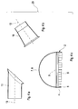
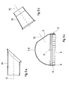
- Fig. 1 und 2
- jeweils einen stark vereinfachten Längsschnitt durch eine Abgasbehandlungseinrichtung im Bereich eines Bodens, bei verschiedenen Ausführungsformen,
- Fig. 3
- Längsschnitte durch eine Haube bei verschiedenen Varianten a, b, c,
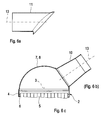
- Fig. 4 bis 6
- Ansichten wie in den
Fig. 1 und 2 , jedoch bei unterschiedlichen Stadien eines Herstellungsverfahrens. - Entsprechend den
Fig. 1 und 2 umfasst eine nur teilweise dargestellte Abgasbehandlungseinrichtung 1, die für eine Verwendung in einer Abgasanlage einer Brennkraftmaschine geeignet ist, ein Gehäuse 2. Dieses Gehäuse 2 weist bezüglich einer Längsmittelachse 3 des Gehäuses 2 einen umfangsseitig geschlossen umlaufenden Mantel 4 auf. Der Mantel 4 umschließt bzw. umhüllt dabei zumindest ein Abgasbehandlungselement 5, wobei zwischen Mantel 4 und Abgasbehandlungselement 5 in üblicher Weise eine Lagermatte 6 angeordnet sein kann. Ferner besitzt das Gehäuse 2 endseitig, also bezüglich seiner Längsmittelachse 3 axial zwei Endböden 7, von denen in denFig. 1 und 2 jeweils nur einer erkennbar ist. - Die Brennkraftmaschine, z.B. ein Dieselmotor oder Ottomotor, kann in Fahrzeugen, in Straßenfahrzeugen, in Baufahrzeugen, in sogenannten non-road-Fahrzeugen sowie in Wasserfahrzeugen, also in Schiffen ebenso zur Anwendung kommen wie in stationären Einrichtungen, wie z. B. Blockheizkraftwerke oder Baumaschinen oder Stromgeneratoren.
- Die Abgasbehandlungseinrichtung 1 kann bspw. als Partikelfiltereinrichtung konzipiert sein. Dementsprechend handelt es sich dann beim Abgasbehandlungselement 5 um ein Partikelfilterelement. Alternativ kann es sich bei der Abgasbehandlungseinrichtung 1 auch um eine Katalysatoreinrichtung handeln, so dass das Abgasbehandlungselement 5 dann ein Katalysatorelement ist. Ebenso sind kombinierte Einrichtungen denkbar, bei denen z. Bsp. ein Oxydationskatalysatorelement stromauf eines Partikelfilterelements angeordnet ist.
- Zumindest einer der Böden 7, hier der gezeigte Boden 7 ist als Haube 8 ausgestaltet, die eine Kugelform bzw. Kugelsegmentform aufweist. In den gezeigten Beispielen ist die Haube 8 als Halbkugel geformt. Die halbkugelförmige Haube 8 ist im Bereich ihres "Äquators" an den Mantel 4 angebaut. Ferner enthält die Haube 8 eine Anschlussöffnung 9, welche die Haube 8 durchsetzt und die im fertigen Zustand der Abgasbehandlungseinrichtung 1 als Einlassöffnung oder als Auslassöffnung für Abgas dienen kann. Außerdem ist an die Haube 8 ein Anschlussstutzen 10 (
Fig. 1 ) bzw. 11 (Fig. 2 ) angebaut. Der Anschlussstutzen 10, 11 ist dabei im Bereich der jeweiligen Anschlussöffnung 9 an die Haube 8 angebaut, so dass besagter Anschlussstutzen 10, 11 durch die jeweilige Anschlussöffnung 9 mit dem Inneren der Haube 8 kommuniziert. In der Folge bildet der jeweilige Anschlussstutzen 10, 11 im fertigen Zustand der Abgasbehandlungseinrichtung 1 einen Einlassstutzen bzw. einen Auslassstutzen für Abgas. Bevorzugt ist der jeweilige Anschlussstutzen 10, 11 an die Haube 8 angeschweißt. Hierzu kann der jeweilige Anschlussstutzen 10, 11 an einem der Haube 8 zugewandten Anschlussende 12 mit einem nach außen abstehenden und bezüglich einer Längsmittelachse 13 des jeweiligen Anschlussstutzens 10, 11 in Umfangsrichtung geschlossen umlaufenden Kragen 14 ausgestattet sein. Zweckmäßig ist besagter Kragen 14 komplementär zur Außenkontur der Haube 8 im Bereich eines die jeweilige Anschlussöffnung 9 einfassenden Öffnungsrands 15 geformt. Hierdurch ergibt sich eine flächige Kontaktierung zwischen Kragen 14 und Öffnungsrand 15, was die Herstellung einer gasdichten Verbindung zwischen Anschlussstutzen 10, 11 und Haube 8 vereinfacht. - Der jeweilige Anschlussstutzen 10, 11 kann geradlinig konfiguriert sein. Dementsprechend besitzt er eine geradlinige Längsmittelachse 13.
- Bei der in
Fig. 1 gezeigten Ausführungsform besitzt der Anschlussstutzen 10 einen kegelstumpfförmigen Abschnitt, der mit zunehmenden Abstand von der Haube 8 leicht konvergiert. Ferner ist bei dieser Ausführungsform das Anschlussende 12 des Anschlussstutzens 10 so konzipiert, dass es in einer Ebene 16 liegt, die sich senkrecht zur Längsmittelachse 13 des Anschlussstutzens 10 erstreckt. - Im Unterschied dazu zeigt
Fig. 2 eine Ausführungsform, bei welcher der Anschlussstutzen 11 zylindrisch geformt ist und dementsprechend über seine gesamte Länge einen konstanten Querschnitt aufweist. Ferner liegt bei dieser Ausführungsform das Anschlussende 12 des Anschlussstutzens 11 in einer Ebene 17, die mit einer Normalebene 18 einen Winkel 19 einschließt, also gegenüber der Normalebene 18 geneigt ist. Besagte Normalebene 18 erstreckt sich senkrecht zur Längsmittelachse 13 des Anschlussstutzens 11. Der inFig. 2 gezeigte Anschlussstutzen 11 ist somit anschlussseitig abgeschrägt. Hierdurch können andere Winkelbereiche zwischen den beiden Längsmittelachsen 3, 13 des jeweiligen Anschlussstutzens 10, 11 und des Gehäuses 2 bzw. des Mantels 4 realisiert werden. Beispielsweise ermöglicht der abgeschrägte Anschlussstutzen 11 einen Winkel von etwa 90° zwischen der Längsmittelachse 3 des Gehäuses 2 und der Längsmittelachse 13 des Anschlussstutzens 11. - Die
Fig. 3a, 3b und 3c zeigen ergänzend drei Ausführungsformen der Haube 8. Die inFig. 3a gezeigte Haube 8 entspricht denjenigen derFig. 1 und 2 . In denFig. 3b bis 3c ist die Haube 8 so gestaltet, dass sie mit Hilfe einer nicht gezeigten Schelle am jeweiligen Mantel 4 lösbar befestigt werden kann. Hierzu ist die Haube 8 an einer dem Mantel 4 zugewandten Seite mit einem bezüglich der Längsmittelachse 3 des Gehäuses 2 umlaufenden Kragen 21 versehen. Dieser kann optional integral an der Haube 8 ausgeformt sein. Im Beispiel derFig. 3c ist an der Haube 8 außerdem eine umlaufende Ringnut 22 am Übergang zum Kragen 21 ausgeformt. In diese Ringnut 22 kann die jeweilige Schelle eingreifen, um mit dem Kragen 21 zusammenzuwirken. Es ist klar, dass auch andere Konfigurationen, insbesondere mit angebautem Kragen, denkbar sind. Ferner ist klar, dass die jeweilige Haube 8 üblicherweise nur eine der Anschlussöffnungen 9 enthält und nicht zwei wie in denFig. 3a bis 3c dargestellt. Außerdem ist denFig. 3a bis 3c entnehmbar, dass die Haube 8 an der dem Mantel 4 zugewandten Seite einen zylindrischen Abschnitt 23 aufweisen kann, der den Anschluss an den zylindrischen Mantel 4 vereinfacht. - Ein erfindungsgemäßer Bausatz ist in
Fig. 4 global mit 20 bezeichnet. Mit Hilfe dieses Bausatzes 20 kann die Abgasbehandlungseinrichtung 1 hergestellt werden. Er umfasst entsprechend denFig. 4a bis 4c zumindest einen Manteltyp zum Herstellen des Mantels 4 des Gehäuses 2 sowie zumindest einen zum jeweiligen Manteltyp passenden Haubentyp zum Herstellen der zum Mantel 4 passenden Haube 8. Ferner umfasst der Bausatz 20 zumindest einen Anschlussstutzentyp. In der Gesamtdarstellung derFig. 4 sind rein exemplarisch die beiden unterschiedlichen Anschlussstutzen 10, 11 derFig. 1 und 2 dargestellt. Der Anschlussstutzen 11 derFig. 4a entspricht dem Anschlussstutzen 11 derFig. 2 , während der Anschlussstutzen 10 derFig. 4b dem Anschlussstutzen 10 derFig. 1 entspricht. Innerhalb des Bausatzes 20 ist die jeweilige Haube 8 ohne die Anschlussöffnung 9 bereitgestellt. Es ist klar, dass der Bausatz 20 auch verschiedene Manteltypen zum Herstellen unterschiedlich dimensionierter Mäntel 4 sowie dazu passende Haubentypen aufweisen kann. Auch können unterschiedlich dimensionierte Anschlussstutzentypen vorhanden sein. - Ein Verfahren zum Herstellen der Abgasbehandlungseinrichtung 1 wird im Folgenden anhand der
Fig. 4 bis 6 näher erläutert. - Zunächst wird entsprechend
Fig. 4 die kugelförmige oder kugelsegmentförmige bzw. halbkugelförmige Haube 8 hergestellt bzw. im Bausatz 20 bereitgestellt. Die Haube 8 ist universell für beliebige Winkel zwischen der Längsmittelachse 3 des Gehäuses 2 und der Längsmittelachse 13 des noch zu montierenden Anschlussstutzens 10, 11 einsetzbar. Die Haube 8 kann bspw. aus einem ebenen Blech durch Tiefziehen oder durch Drücken hergestellt werden. - Sobald der einzuhaltende Winkel zwischen der Längsmittelachse 3 des Gehäuses 2 und der Längsmittelachse 13 des jeweiligen Anschlussstutzens 10, 11 feststeht, wird an einer dafür geeigneten Stelle der Haube 8 die Anschlussöffnung 9 hergestellt, was im Zustand der
Fig. 5 wiedergegeben ist. Die Anschlussöffnung 9 kann bspw. mittels eines geeigneten Schneidwerkzeugs oder mittels eines Stanzwerkzeugs oder mittels eines Laserschweißverfahrens hergestellt werden. Durch die Positionierung der Anschlussöffnung 9 liegt die Längsmittelachse 13 des späteren Anschlussstutzens 10, 11 bereits mehr oder weniger fest, zumindest wenn es sich um den geradlinigen Anschlussstutzen 10 gemäßFig. 5b handelt. - Anschließend kann der passende Anschlussstutzen, hier der geradlinige Anschlussstutzen 10 entsprechend
Fig. 6 montiert werden. Hierzu wird der jeweilige Anschlussstutzen 10 im Bereich der Anschlussöffnung 9 an die Haube 8 angebaut. Wie erwähnt, lässt sich der Anschlussstutzen 10 bspw. an die Haube 8 anschweißen oder anlöten. Der inFig. 6c gezeigte Zustand entspricht hier der Darstellung gemäßFig. 1 . - Im gezeigten Beispiel ist die Haube 8 bereits in einem Zustand, in dem sie noch keine Anschlussöffnung 9 aufweist, an den Mantel 4 angebaut. Es ist klar, dass die Haube 8 auch zu einem späteren Zeitpunkt, insbesondere nach dem Herstellen der Anschlussöffnung 9 und/oder nach dem Anbauen des jeweiligen Anschlussstutzens 10, 11, an den Mantel 4 angebaut werden kann.
- Beim Verbinden von Haube 8 und Mantel 4 können die üblichen Herstellungsmethoden berücksichtigt werden, insbesondere auch ein Downsizing oder Zusammendrücken des Mantels 4 im Rahmen des Canning-Prozesses, bei dem der jeweilige Abgasbehandlungseinsatz 5 in den Mantel 4 eingesetzt wird und bei dem der jeweilige Mantel 4 an die Abmessungen des jeweiligen Abgasbehandlungseinsatzes 5 angepasst wird.
- Es ist klar, dass die einzelnen Merkmale der hier gezeigten unterschiedlichen Ausführungsformen auch beliebig miteinander kombinierbar sind, um dadurch gemischte oder neue Ausführungsformen zu erzielen.
Claims (13)
- Verfahren zum Herstellen einer Abgasbehandlungseinrichtung (1) für eine Abgasanlage einer Brennkraftmaschine,- wobei die Abgasbehandlungseinrichtung (1) ein Gehäuse (2) aufweist, das umfangsseitig einen Mantel (4) und endseitig zumindest einen Boden (7) aufweist,- bei dem zumindest ein solcher Boden (7) als kugelförmige oder kugelsegmentförmige Haube (8) hergestellt wird,- bei dem in die Haube (8) eine Anschlussöffnung (9) eingebracht wird,- bei dem ein Anschlussstutzen (10, 11) im Bereich der Anschlussöffnung (9) an die Haube (8) angebaut wird.
- Verfahren nach Anspruch 1,
dadurch gekennzeichnet,
dass der Anschlussstutzen (10, 11) an die Haube (8) angeschweißt wird. - Verfahren nach Anspruch 1 oder 2,
dadurch gekennzeichnet,
dass der Anschlussstutzen (10, 11) geradlinig konfiguriert wird. - Verfahren nach einem der Ansprüche 1 bis 3,
dadurch gekennzeichnet,
dass der Anschlussstutzen (10, 11) an seinem der Haube (8) zugewandten Anschlussende (12) komplementär zur Außenkontur der Haube (8) geformt wird. - Verfahren nach einem der Ansprüche 1 bis 4,
dadurch gekennzeichnet,
dass der Anschlussstutzen (11) mit seinem der Haube (8) zugewandten Anschlussende (12) in einer Ebene (17) liegt, die gegenüber einer senkrecht auf der Längsmittelachse (13) des Anschlussstutzens (11) stehenden Normalebene (18) geneigt ist. - Abgasbehandlungseinrichtung für eine Abgasanlage einer Brennkraftmaschine, insbesondere eines Kraftfahrzeugs,- mit einem Gehäuse (2), das einen Mantel (4) und endseitig zumindest einen Boden (7) aufweist,- wobei zumindest ein solcher Boden (7) als kugelförmige oder kugelsegmentförmige Haube (8) ausgestaltet ist,- wobei die Haube (8) eine Anschlussöffnung (9) aufweist,- wobei an die Haube (8) im Bereich der Anschlussöffnung (9) ein Anschlussstutzen (10, 11) angebaut ist.
- Abgasbehandlungseinrichtung nach Anspruch 6,
dadurch gekennzeichnet,
dass der Anschlussstutzen (10, 11) an die Haube (8) angeschweißt ist. - Abgasbehandlungseinrichtung nach Anspruch 6 oder 7,
dadurch gekennzeichnet,
dass der Anschlussstutzen (10, 11) geradlinig konfiguriert ist. - Abgasbehandlungseinrichtung nach einem der Ansprüche 6 bis 8,
dadurch gekennzeichnet,
dass der Anschlussstutzen (10, 11) an seinem der Haube (8) zugewandten Anschlussende (12) komplementär zur Außenkontur der Haube (8) geformt ist. - Abgasbehandlungseinrichtung nach einem der Ansprüche 6 bis 9,
dadurch gekennzeichnet,
dass der Anschlussstutzen (11) mit seinem der Haube (8) zugewandten Anschlussende (12) in einer Ebene (17) liegt, die gegenüber einer senkrecht auf der Längsmittelachse (13) des Anschlussstutzens (11) stehenden Normalebene (18) geneigt ist. - Abgasbehandlungseinrichtung n ach einem der Ansprüche 6 bis 10,
dadurch gekennzeichnet,
dass die Haube (8) mittels einer Schelle lösbar am Mantel (4) befestigt ist. - Abgasbehandlungseinrichtung nach Anspruch 11,
dadurch gekennzeichnet,
dass an der Haube (8) ein umlaufender Kragen (21) integral ausgeformt ist, der mit der Schelle zusammenwirkt. - Bausatz zum Herstellen von Abgasbehandlungseinrichtungen (1) nach einem der Ansprüche 6 bis 12 und/oder zum Herstellen von Abgasbehandlungseinrichtungen (1) mit dem Verfahren nach einem der Ansprüche 1 bis 5,- der zumindest einen Manteltyp zum Herstellen des Mantels (4) des Gehäuses (2) aufweist,- das zumindest einen Haubentyp zum Herstellen des jeweiligen Bodens (7) des Gehäuses (2) aufweist,- der zumindest einen Anschlussstutzentyp zum Anbauen des jeweiligen Anschlussstutzens (10, 11) an die mit der Anschlussöffnung (9) versehene Haube (8) aufweist.
Applications Claiming Priority (1)
| Application Number | Priority Date | Filing Date | Title |
|---|---|---|---|
| DE102009015625A DE102009015625A1 (de) | 2009-04-02 | 2009-04-02 | Abgasbehandlungseinrichtung und zugehöriges Herstellungsverfahren |
Publications (2)
| Publication Number | Publication Date |
|---|---|
| EP2239434A1 true EP2239434A1 (de) | 2010-10-13 |
| EP2239434B1 EP2239434B1 (de) | 2012-05-16 |
Family
ID=42153694
Family Applications (1)
| Application Number | Title | Priority Date | Filing Date |
|---|---|---|---|
| EP10155413A Revoked EP2239434B1 (de) | 2009-04-02 | 2010-03-04 | Verfahren zur Herstellung eines Gehäuses für eine Abgasbehandlungseinrichtung und Gehäuse und Bausatz |
Country Status (3)
| Country | Link |
|---|---|
| US (1) | US20110083421A1 (de) |
| EP (1) | EP2239434B1 (de) |
| DE (1) | DE102009015625A1 (de) |
Families Citing this family (1)
| Publication number | Priority date | Publication date | Assignee | Title |
|---|---|---|---|---|
| US9387438B2 (en) | 2014-02-14 | 2016-07-12 | Tenneco Automotive Operating Company Inc. | Modular system for reduction of sulphur oxides in exhaust |
Citations (4)
| Publication number | Priority date | Publication date | Assignee | Title |
|---|---|---|---|---|
| US4969264A (en) * | 1986-06-12 | 1990-11-13 | Tennessee Gas Pipeline Company | Catalytic converter and substrate support |
| EP1596049A1 (de) * | 2004-05-14 | 2005-11-16 | Dr.Ing. H.C. F. Porsche Aktiengesellschaft | Verbindungsvorrichtung |
| DE102005002857A1 (de) * | 2005-01-20 | 2006-08-03 | J. Eberspächer GmbH & Co. KG | Abgasbehandlungsvorrichtung |
| EP1990514A1 (de) * | 2007-05-09 | 2008-11-12 | Delphi Technologies, Inc. | Abgasrohranbindung für eine Abgasbehandlungsvorrichtung |
Family Cites Families (3)
| Publication number | Priority date | Publication date | Assignee | Title |
|---|---|---|---|---|
| US3523590A (en) * | 1968-12-18 | 1970-08-11 | Tenneco Inc | Simplified muffler shell construction |
| EP1799980A1 (de) * | 2004-09-08 | 2007-06-27 | Donaldson Company, Inc. | Konstruktion für eine motorabgassystemkomponente |
| FR2905405B1 (fr) * | 2006-09-01 | 2008-11-07 | Renault Sas | Agencement pour le raccordement d'un conduit a un organe de depollution d'une ligne d'echappement d'un moteur a combustion |
-
2009
- 2009-04-02 DE DE102009015625A patent/DE102009015625A1/de not_active Withdrawn
-
2010
- 2010-03-04 EP EP10155413A patent/EP2239434B1/de not_active Revoked
- 2010-04-01 US US12/752,484 patent/US20110083421A1/en not_active Abandoned
Patent Citations (4)
| Publication number | Priority date | Publication date | Assignee | Title |
|---|---|---|---|---|
| US4969264A (en) * | 1986-06-12 | 1990-11-13 | Tennessee Gas Pipeline Company | Catalytic converter and substrate support |
| EP1596049A1 (de) * | 2004-05-14 | 2005-11-16 | Dr.Ing. H.C. F. Porsche Aktiengesellschaft | Verbindungsvorrichtung |
| DE102005002857A1 (de) * | 2005-01-20 | 2006-08-03 | J. Eberspächer GmbH & Co. KG | Abgasbehandlungsvorrichtung |
| EP1990514A1 (de) * | 2007-05-09 | 2008-11-12 | Delphi Technologies, Inc. | Abgasrohranbindung für eine Abgasbehandlungsvorrichtung |
Also Published As
| Publication number | Publication date |
|---|---|
| US20110083421A1 (en) | 2011-04-14 |
| EP2239434B1 (de) | 2012-05-16 |
| DE102009015625A1 (de) | 2010-10-07 |
Similar Documents
| Publication | Publication Date | Title |
|---|---|---|
| EP0818615B1 (de) | Katalysatorgehäuse | |
| EP1967709B1 (de) | Abgasbehandlungseinrichtung und zugehöriges Herstellungsverfahren | |
| EP2757235B1 (de) | Schalldämpfer und Verfahren zu seiner Herstellung | |
| EP2852738B1 (de) | Abgasnachbehandlungseinrichtung und zugehöriges herstellungsverfahren | |
| EP2799681A1 (de) | Abgasanlagenkomponente | |
| WO2012146379A2 (de) | Verfahren zum herstellen von anschlussbuchsen | |
| DE102015008328A1 (de) | Filteranschlusseinrichtung, Filtereinrichtung und Verbindungsvorrichtung zur Verbindung eines Filters mit einer Filteranschlusseinrichtung | |
| EP3037150B1 (de) | Filtereinrichtung | |
| EP2239434B1 (de) | Verfahren zur Herstellung eines Gehäuses für eine Abgasbehandlungseinrichtung und Gehäuse und Bausatz | |
| DE102010032319A1 (de) | Flanschverbindung | |
| EP2915973B1 (de) | Trichter-Rohr-Anordnung | |
| WO2013068153A2 (de) | Elektromotorbaugruppe | |
| WO2012035163A1 (de) | Abgasbehandlungseinheit für eine abgasrückführleitung | |
| EP1875053B1 (de) | Abgasleitungsabschnitt | |
| DE102011002492A1 (de) | Flanschbauteil und Herstellungsverfahren | |
| DE102019100741A1 (de) | Verfahren zur Herstellung eines Schalldämpfers, Schalldämpfer sowie Fahrzeug | |
| DE102005002857B4 (de) | Baukastensystem für eine Abgasbehandlungsvorrichtung | |
| DE19962311B4 (de) | Katalytische Abgasreinigungsvorrichtung | |
| EP1941137A1 (de) | Gehäuse für ein bauteil einer abgasanlage sowie verfahren zur herstellung eines solchen gehäuses | |
| DE10358504A1 (de) | Verfahren zur Herstellung eines Katalysatorgehäuses | |
| DE102010044064B4 (de) | Katalysator und Abgasanlage | |
| DE102005024831A1 (de) | Schalldämpfer für eine Abgasanlage und Herstellungsverfahren | |
| EP1118749A2 (de) | Abgaskatalysator | |
| DE102011112973A1 (de) | Anschlussverbindung und Verfahren zum Verbinden eines flexiblen Leitungsteils aus Metall mit einem Anschlussteil | |
| DE102017128607A1 (de) | Gehäuseanschlusselement |
Legal Events
| Date | Code | Title | Description |
|---|---|---|---|
| PUAI | Public reference made under article 153(3) epc to a published international application that has entered the european phase |
Free format text: ORIGINAL CODE: 0009012 |
|
| AK | Designated contracting states |
Kind code of ref document: A1 Designated state(s): AT BE BG CH CY CZ DE DK EE ES FI FR GB GR HR HU IE IS IT LI LT LU LV MC MK MT NL NO PL PT RO SE SI SK SM TR |
|
| AX | Request for extension of the european patent |
Extension state: AL BA ME RS |
|
| 17P | Request for examination filed |
Effective date: 20110413 |
|
| 17Q | First examination report despatched |
Effective date: 20110511 |
|
| RIC1 | Information provided on ipc code assigned before grant |
Ipc: F01N 3/28 20060101ALI20111125BHEP Ipc: F01N 13/18 20100101AFI20111125BHEP |
|
| GRAP | Despatch of communication of intention to grant a patent |
Free format text: ORIGINAL CODE: EPIDOSNIGR1 |
|
| RTI1 | Title (correction) |
Free format text: METHOD FOR MANUFACTURING A CASING FOR AN EXHAUST GAS CLEANING DEVICE AND CASING AND KIT |
|
| RTI1 | Title (correction) |
Free format text: METHOD FOR MANUFACTURING A CASING FOR AN EXHAUST GAS TREATMENT DEVICE AND CASING AND KIT |
|
| GRAS | Grant fee paid |
Free format text: ORIGINAL CODE: EPIDOSNIGR3 |
|
| GRAA | (expected) grant |
Free format text: ORIGINAL CODE: 0009210 |
|
| AK | Designated contracting states |
Kind code of ref document: B1 Designated state(s): AT BE BG CH CY CZ DE DK EE ES FI FR GB GR HR HU IE IS IT LI LT LU LV MC MK MT NL NO PL PT RO SE SI SK SM TR |
|
| REG | Reference to a national code |
Ref country code: GB Ref legal event code: FG4D Free format text: NOT ENGLISH |
|
| REG | Reference to a national code |
Ref country code: CH Ref legal event code: EP |
|
| REG | Reference to a national code |
Ref country code: AT Ref legal event code: REF Ref document number: 558212 Country of ref document: AT Kind code of ref document: T Effective date: 20120615 |
|
| REG | Reference to a national code |
Ref country code: IE Ref legal event code: FG4D Free format text: LANGUAGE OF EP DOCUMENT: GERMAN |
|
| REG | Reference to a national code |
Ref country code: DE Ref legal event code: R096 Ref document number: 502010000754 Country of ref document: DE Effective date: 20120712 |
|
| REG | Reference to a national code |
Ref country code: SE Ref legal event code: TRGR |
|
| REG | Reference to a national code |
Ref country code: NL Ref legal event code: VDEP Effective date: 20120516 |
|
| REG | Reference to a national code |
Ref country code: LT Ref legal event code: MG4D Effective date: 20120516 |
|
| PG25 | Lapsed in a contracting state [announced via postgrant information from national office to epo] |
Ref country code: LT Free format text: LAPSE BECAUSE OF FAILURE TO SUBMIT A TRANSLATION OF THE DESCRIPTION OR TO PAY THE FEE WITHIN THE PRESCRIBED TIME-LIMIT Effective date: 20120516 Ref country code: PL Free format text: LAPSE BECAUSE OF FAILURE TO SUBMIT A TRANSLATION OF THE DESCRIPTION OR TO PAY THE FEE WITHIN THE PRESCRIBED TIME-LIMIT Effective date: 20120516 Ref country code: IS Free format text: LAPSE BECAUSE OF FAILURE TO SUBMIT A TRANSLATION OF THE DESCRIPTION OR TO PAY THE FEE WITHIN THE PRESCRIBED TIME-LIMIT Effective date: 20120916 Ref country code: CY Free format text: LAPSE BECAUSE OF FAILURE TO SUBMIT A TRANSLATION OF THE DESCRIPTION OR TO PAY THE FEE WITHIN THE PRESCRIBED TIME-LIMIT Effective date: 20120516 Ref country code: NO Free format text: LAPSE BECAUSE OF FAILURE TO SUBMIT A TRANSLATION OF THE DESCRIPTION OR TO PAY THE FEE WITHIN THE PRESCRIBED TIME-LIMIT Effective date: 20120816 Ref country code: FI Free format text: LAPSE BECAUSE OF FAILURE TO SUBMIT A TRANSLATION OF THE DESCRIPTION OR TO PAY THE FEE WITHIN THE PRESCRIBED TIME-LIMIT Effective date: 20120516 |
|
| PG25 | Lapsed in a contracting state [announced via postgrant information from national office to epo] |
Ref country code: LV Free format text: LAPSE BECAUSE OF FAILURE TO SUBMIT A TRANSLATION OF THE DESCRIPTION OR TO PAY THE FEE WITHIN THE PRESCRIBED TIME-LIMIT Effective date: 20120516 Ref country code: GR Free format text: LAPSE BECAUSE OF FAILURE TO SUBMIT A TRANSLATION OF THE DESCRIPTION OR TO PAY THE FEE WITHIN THE PRESCRIBED TIME-LIMIT Effective date: 20120817 Ref country code: SI Free format text: LAPSE BECAUSE OF FAILURE TO SUBMIT A TRANSLATION OF THE DESCRIPTION OR TO PAY THE FEE WITHIN THE PRESCRIBED TIME-LIMIT Effective date: 20120516 Ref country code: HR Free format text: LAPSE BECAUSE OF FAILURE TO SUBMIT A TRANSLATION OF THE DESCRIPTION OR TO PAY THE FEE WITHIN THE PRESCRIBED TIME-LIMIT Effective date: 20120516 Ref country code: PT Free format text: LAPSE BECAUSE OF FAILURE TO SUBMIT A TRANSLATION OF THE DESCRIPTION OR TO PAY THE FEE WITHIN THE PRESCRIBED TIME-LIMIT Effective date: 20120917 |
|
| PG25 | Lapsed in a contracting state [announced via postgrant information from national office to epo] |
Ref country code: CZ Free format text: LAPSE BECAUSE OF FAILURE TO SUBMIT A TRANSLATION OF THE DESCRIPTION OR TO PAY THE FEE WITHIN THE PRESCRIBED TIME-LIMIT Effective date: 20120516 Ref country code: DK Free format text: LAPSE BECAUSE OF FAILURE TO SUBMIT A TRANSLATION OF THE DESCRIPTION OR TO PAY THE FEE WITHIN THE PRESCRIBED TIME-LIMIT Effective date: 20120516 Ref country code: RO Free format text: LAPSE BECAUSE OF FAILURE TO SUBMIT A TRANSLATION OF THE DESCRIPTION OR TO PAY THE FEE WITHIN THE PRESCRIBED TIME-LIMIT Effective date: 20120516 Ref country code: EE Free format text: LAPSE BECAUSE OF FAILURE TO SUBMIT A TRANSLATION OF THE DESCRIPTION OR TO PAY THE FEE WITHIN THE PRESCRIBED TIME-LIMIT Effective date: 20120516 Ref country code: NL Free format text: LAPSE BECAUSE OF FAILURE TO SUBMIT A TRANSLATION OF THE DESCRIPTION OR TO PAY THE FEE WITHIN THE PRESCRIBED TIME-LIMIT Effective date: 20120516 Ref country code: SK Free format text: LAPSE BECAUSE OF FAILURE TO SUBMIT A TRANSLATION OF THE DESCRIPTION OR TO PAY THE FEE WITHIN THE PRESCRIBED TIME-LIMIT Effective date: 20120516 |
|
| PLBI | Opposition filed |
Free format text: ORIGINAL CODE: 0009260 |
|
| PG25 | Lapsed in a contracting state [announced via postgrant information from national office to epo] |
Ref country code: IT Free format text: LAPSE BECAUSE OF FAILURE TO SUBMIT A TRANSLATION OF THE DESCRIPTION OR TO PAY THE FEE WITHIN THE PRESCRIBED TIME-LIMIT Effective date: 20120516 |
|
| 26 | Opposition filed |
Opponent name: TENNECO GMBH Effective date: 20130212 |
|
| PLAX | Notice of opposition and request to file observation + time limit sent |
Free format text: ORIGINAL CODE: EPIDOSNOBS2 |
|
| PG25 | Lapsed in a contracting state [announced via postgrant information from national office to epo] |
Ref country code: ES Free format text: LAPSE BECAUSE OF FAILURE TO SUBMIT A TRANSLATION OF THE DESCRIPTION OR TO PAY THE FEE WITHIN THE PRESCRIBED TIME-LIMIT Effective date: 20120827 |
|
| REG | Reference to a national code |
Ref country code: DE Ref legal event code: R026 Ref document number: 502010000754 Country of ref document: DE Effective date: 20130212 |
|
| RAP2 | Party data changed (patent owner data changed or rights of a patent transferred) |
Owner name: EBERSPAECHER EXHAUST TECHNOLOGY GMBH & CO. KG |
|
| PG25 | Lapsed in a contracting state [announced via postgrant information from national office to epo] |
Ref country code: BG Free format text: LAPSE BECAUSE OF FAILURE TO SUBMIT A TRANSLATION OF THE DESCRIPTION OR TO PAY THE FEE WITHIN THE PRESCRIBED TIME-LIMIT Effective date: 20120816 |
|
| BERE | Be: lapsed |
Owner name: J. EBERSPACHER G.M.B.H. & CO. KG Effective date: 20130331 |
|
| REG | Reference to a national code |
Ref country code: GB Ref legal event code: 732E Free format text: REGISTERED BETWEEN 20130905 AND 20130911 |
|
| PLAX | Notice of opposition and request to file observation + time limit sent |
Free format text: ORIGINAL CODE: EPIDOSNOBS2 |
|
| PG25 | Lapsed in a contracting state [announced via postgrant information from national office to epo] |
Ref country code: MC Free format text: LAPSE BECAUSE OF NON-PAYMENT OF DUE FEES Effective date: 20130331 |
|
| REG | Reference to a national code |
Ref country code: DE Ref legal event code: R082 Ref document number: 502010000754 Country of ref document: DE Representative=s name: BRP RENAUD & PARTNER, DE |
|
| PLBB | Reply of patent proprietor to notice(s) of opposition received |
Free format text: ORIGINAL CODE: EPIDOSNOBS3 |
|
| REG | Reference to a national code |
Ref country code: DE Ref legal event code: R082 Ref document number: 502010000754 Country of ref document: DE Representative=s name: BRP RENAUD UND PARTNER MBB RECHTSANWAELTE PATE, DE Effective date: 20131104 Ref country code: DE Ref legal event code: R082 Ref document number: 502010000754 Country of ref document: DE Representative=s name: BRP RENAUD UND PARTNER MBB, DE Effective date: 20131104 Ref country code: DE Ref legal event code: R082 Ref document number: 502010000754 Country of ref document: DE Representative=s name: RLTG RUTTENSPERGER LACHNIT TROSSIN GOMOLL PATE, DE Effective date: 20131104 Ref country code: DE Ref legal event code: R082 Ref document number: 502010000754 Country of ref document: DE Representative=s name: BRP RENAUD & PARTNER, DE Effective date: 20131104 Ref country code: DE Ref legal event code: R081 Ref document number: 502010000754 Country of ref document: DE Owner name: EBERSPAECHER EXHAUST TECHNOLOGY GMBH & CO. KG, DE Free format text: FORMER OWNER: J. EBERSPAECHER GMBH & CO. KG, 73730 ESSLINGEN, DE Effective date: 20131104 |
|
| REG | Reference to a national code |
Ref country code: IE Ref legal event code: MM4A |
|
| PG25 | Lapsed in a contracting state [announced via postgrant information from national office to epo] |
Ref country code: BE Free format text: LAPSE BECAUSE OF NON-PAYMENT OF DUE FEES Effective date: 20130331 Ref country code: IE Free format text: LAPSE BECAUSE OF NON-PAYMENT OF DUE FEES Effective date: 20130304 |
|
| PG25 | Lapsed in a contracting state [announced via postgrant information from national office to epo] |
Ref country code: MT Free format text: LAPSE BECAUSE OF FAILURE TO SUBMIT A TRANSLATION OF THE DESCRIPTION OR TO PAY THE FEE WITHIN THE PRESCRIBED TIME-LIMIT Effective date: 20120516 |
|
| REG | Reference to a national code |
Ref country code: CH Ref legal event code: PL |
|
| PG25 | Lapsed in a contracting state [announced via postgrant information from national office to epo] |
Ref country code: LI Free format text: LAPSE BECAUSE OF NON-PAYMENT OF DUE FEES Effective date: 20140331 Ref country code: CH Free format text: LAPSE BECAUSE OF NON-PAYMENT OF DUE FEES Effective date: 20140331 |
|
| PG25 | Lapsed in a contracting state [announced via postgrant information from national office to epo] |
Ref country code: SM Free format text: LAPSE BECAUSE OF FAILURE TO SUBMIT A TRANSLATION OF THE DESCRIPTION OR TO PAY THE FEE WITHIN THE PRESCRIBED TIME-LIMIT Effective date: 20120516 |
|
| PG25 | Lapsed in a contracting state [announced via postgrant information from national office to epo] |
Ref country code: TR Free format text: LAPSE BECAUSE OF FAILURE TO SUBMIT A TRANSLATION OF THE DESCRIPTION OR TO PAY THE FEE WITHIN THE PRESCRIBED TIME-LIMIT Effective date: 20120516 |
|
| PG25 | Lapsed in a contracting state [announced via postgrant information from national office to epo] |
Ref country code: LU Free format text: LAPSE BECAUSE OF NON-PAYMENT OF DUE FEES Effective date: 20130304 Ref country code: MK Free format text: LAPSE BECAUSE OF FAILURE TO SUBMIT A TRANSLATION OF THE DESCRIPTION OR TO PAY THE FEE WITHIN THE PRESCRIBED TIME-LIMIT Effective date: 20120516 Ref country code: HU Free format text: LAPSE BECAUSE OF FAILURE TO SUBMIT A TRANSLATION OF THE DESCRIPTION OR TO PAY THE FEE WITHIN THE PRESCRIBED TIME-LIMIT; INVALID AB INITIO Effective date: 20100304 |
|
| PLAB | Opposition data, opponent's data or that of the opponent's representative modified |
Free format text: ORIGINAL CODE: 0009299OPPO |
|
| R26 | Opposition filed (corrected) |
Opponent name: TENNECO GMBH Effective date: 20130212 |
|
| REG | Reference to a national code |
Ref country code: DE Ref legal event code: R082 Ref document number: 502010000754 Country of ref document: DE Representative=s name: RLTG RUTTENSPERGER LACHNIT TROSSIN GOMOLL PATE, DE |
|
| REG | Reference to a national code |
Ref country code: DE Ref legal event code: R064 Ref document number: 502010000754 Country of ref document: DE Ref country code: DE Ref legal event code: R103 Ref document number: 502010000754 Country of ref document: DE |
|
| RDAF | Communication despatched that patent is revoked |
Free format text: ORIGINAL CODE: EPIDOSNREV1 |
|
| REG | Reference to a national code |
Ref country code: FR Ref legal event code: PLFP Year of fee payment: 7 |
|
| PGFP | Annual fee paid to national office [announced via postgrant information from national office to epo] |
Ref country code: DE Payment date: 20160322 Year of fee payment: 7 |
|
| REG | Reference to a national code |
Ref country code: AT Ref legal event code: MM01 Ref document number: 558212 Country of ref document: AT Kind code of ref document: T Effective date: 20150304 |
|
| PGFP | Annual fee paid to national office [announced via postgrant information from national office to epo] |
Ref country code: FR Payment date: 20160322 Year of fee payment: 7 Ref country code: GB Payment date: 20160322 Year of fee payment: 7 Ref country code: SE Payment date: 20160322 Year of fee payment: 7 |
|
| RDAG | Patent revoked |
Free format text: ORIGINAL CODE: 0009271 |
|
| STAA | Information on the status of an ep patent application or granted ep patent |
Free format text: STATUS: PATENT REVOKED |
|
| 27W | Patent revoked |
Effective date: 20160301 |
|
| GBPR | Gb: patent revoked under art. 102 of the ep convention designating the uk as contracting state |
Effective date: 20160301 |
|
| PG25 | Lapsed in a contracting state [announced via postgrant information from national office to epo] |
Ref country code: AT Free format text: LAPSE BECAUSE OF NON-PAYMENT OF DUE FEES Effective date: 20150304 |
|
| REG | Reference to a national code |
Ref country code: AT Ref legal event code: MA03 Ref document number: 558212 Country of ref document: AT Kind code of ref document: T Effective date: 20160301 |
|
| REG | Reference to a national code |
Ref country code: SE Ref legal event code: ECNC |