EP2239338B1 - Fluidtransferkontrolle - Google Patents
Fluidtransferkontrolle Download PDFInfo
- Publication number
- EP2239338B1 EP2239338B1 EP10003757.1A EP10003757A EP2239338B1 EP 2239338 B1 EP2239338 B1 EP 2239338B1 EP 10003757 A EP10003757 A EP 10003757A EP 2239338 B1 EP2239338 B1 EP 2239338B1
- Authority
- EP
- European Patent Office
- Prior art keywords
- intensity
- fluid transfer
- vessels
- quenching
- parameter value
- Prior art date
- Legal status (The legal status is an assumption and is not a legal conclusion. Google has not performed a legal analysis and makes no representation as to the accuracy of the status listed.)
- Active
Links
Images

Classifications
-
- G—PHYSICS
- G01—MEASURING; TESTING
- G01N—INVESTIGATING OR ANALYSING MATERIALS BY DETERMINING THEIR CHEMICAL OR PHYSICAL PROPERTIES
- G01N35/00—Automatic analysis not limited to methods or materials provided for in any single one of groups G01N1/00 - G01N33/00; Handling materials therefor
- G01N35/10—Devices for transferring samples or any liquids to, in, or from, the analysis apparatus, e.g. suction devices, injection devices
- G01N35/1009—Characterised by arrangements for controlling the aspiration or dispense of liquids
- G01N35/1016—Control of the volume dispensed or introduced
-
- G—PHYSICS
- G01—MEASURING; TESTING
- G01N—INVESTIGATING OR ANALYSING MATERIALS BY DETERMINING THEIR CHEMICAL OR PHYSICAL PROPERTIES
- G01N21/00—Investigating or analysing materials by the use of optical means, i.e. using sub-millimetre waves, infrared, visible or ultraviolet light
- G01N21/62—Systems in which the material investigated is excited whereby it emits light or causes a change in wavelength of the incident light
- G01N21/63—Systems in which the material investigated is excited whereby it emits light or causes a change in wavelength of the incident light optically excited
- G01N21/64—Fluorescence; Phosphorescence
- G01N21/6428—Measuring fluorescence of fluorescent products of reactions or of fluorochrome labelled reactive substances, e.g. measuring quenching effects, using measuring "optrodes"
-
- G—PHYSICS
- G01—MEASURING; TESTING
- G01N—INVESTIGATING OR ANALYSING MATERIALS BY DETERMINING THEIR CHEMICAL OR PHYSICAL PROPERTIES
- G01N21/00—Investigating or analysing materials by the use of optical means, i.e. using sub-millimetre waves, infrared, visible or ultraviolet light
- G01N21/62—Systems in which the material investigated is excited whereby it emits light or causes a change in wavelength of the incident light
- G01N21/63—Systems in which the material investigated is excited whereby it emits light or causes a change in wavelength of the incident light optically excited
- G01N21/64—Fluorescence; Phosphorescence
- G01N21/6428—Measuring fluorescence of fluorescent products of reactions or of fluorochrome labelled reactive substances, e.g. measuring quenching effects, using measuring "optrodes"
- G01N2021/6432—Quenching
-
- G—PHYSICS
- G01—MEASURING; TESTING
- G01N—INVESTIGATING OR ANALYSING MATERIALS BY DETERMINING THEIR CHEMICAL OR PHYSICAL PROPERTIES
- G01N21/00—Investigating or analysing materials by the use of optical means, i.e. using sub-millimetre waves, infrared, visible or ultraviolet light
- G01N21/84—Systems specially adapted for particular applications
- G01N2021/8411—Application to online plant, process monitoring
- G01N2021/8416—Application to online plant, process monitoring and process controlling, not otherwise provided for
Definitions
- the normalization method (1) can only control the amount/quality of the sample material when relative quantification is applied, not when absolute quantification is used. Furthermore, this method does not control the amount of any other PCR component besides the sample material.
- the normalization method (2) only normalizes against fluorescence intensity differences generated by qPCR system variations. It does not control or warn the user when the amount of a certain component is below a certain limit.
- the use of a passive internal reference dye in order to determine if sample filling errors have occurred by looking for an absent or abnormally high or low signal is known from US2005/0232818 A1 .
- US2007/0141709 A1 shows a method for mixing a test-stock mixture containing a first dye which absorbs at a first wavelength and a second dye which absorbs at a second wavelength with a diluent containing the second dye only.
- the present invention provides a closed system for assay set-up that encompasses control strategies to identify volume errors of components mixed for said assays.
- the method according to the present invention is especially suitable for the set-up of real time PCR amplifications.
- One aspect of the present invention is a fluid transfer control method, as set out in independent claim 1 or independent claim 2.
- “Solution” is used throughout the present invention as generic term for all kinds of liquid components that need to be transferred into a vessel for a subsequent reaction in said vessel, wherein said reaction may need additional components to be added to said vessel. Consequently, the method according to the present invention can be applied for each of the transfer steps that need to be performed prior to said reaction. If more than one solution is transferred to one reaction vessel, each of said solutions may be mixed with a different, distinguishing dye. Alternatively, each solution can have the same dye and the change of intensity after each step can be used for the transfer control.
- control dyes are used as transfer controls.
- the presence of the control dyes can be measured using suitable machinery depending on the used dyes, e.g. PMTs or CCD chips for optical dyes or scintillation counters in case of radioactive dyes.
- the measured intensities are processed by a software module and said software module compares the calculated values with certain thresholds (e.g. minimum fluorescence, range of deviation from a mean value).
- the software module generates an output signal that either (a) warns the user that certain vessel failed the transfer control check ("soft closing") or (b) inhibits result calculation of vessels failing the transfer control ("hard closing").
- the software module can be used to avoid the further processing of the vessels with a detected transfer error.
- An advantage of the present invention is the independent check of transfer volume correctness for all components that are required for a certain application in an automated fashion. Particularly, when automatic liquid handling systems (pipetting robots) are used for the reaction setup, no manual control by eye is applicable to the process. Furthermore, controlling the transfer process in low volume applications (total reaction volume ⁇ 3 ⁇ l) is of especial relevance as liquid handling of (sub-) microlitre volumes is highly critical concerning accuracy and reproducibility.
- Another aspect of the present invention is a fluid transfer control method in a real-time PCR amplification workflow, the method comprising
- the fluid transfer control method in a real-time PCR amplification workflow according to the present invention can also be preformed with step
- each component may contain the same or different dyes as transfer controls.
- the intensity of each dye is measured using a real time PCR instrument.
- one control dye is contained in the qPCR master mix
- the second control dye is contained in the sample material
- a third control dye is contained in the primer/probes mixture.
- the first steps of the fluid transfer control method of the present invention are as follows:
- said plurality of vessels are arranged as a multiwell plate, said multiwell plate has at least 8 wells, preferably at least 96 wells, more preferably at least 384 wells, most preferably at least 1536 wells.
- said threshold value of step d) is pre-defined based on measured intensity values using a reference solution, said reference solution having the volume and the control dye concentration of step b).
- the threshold value is used as a first transfer control in order to detect vessels without any solution and consequently without any intensity as well as vessels that obtained only a minor portion of the pre-defined volume.
- the background intensity of empty vessels can be used to define the pre-defined threshold value, e.g. the threshold value can be defined as three time the background intensity.
- a second transfer control is performed to evaluate the deviation between the vessels, because said deviations pose problems with regard to meaningful comparisons of said vessels.
- Said second pipetting control is based on a pre-defined range surrounding the mean intensity value of all vessels that passed the first pipetting control. Depending on the measured intensity, the vessel will be flagged as "range control passed” or "range control failed".
- This second pipetting control is of particular importance in situations with a high variance of the solution to be transferred between each use of the method.
- This variance of the solution to be transferred may originate from an volume off-set between subsequent applications of the method or from a shift of the control dye concentration. In such a situation it is not possible to set a meaningful threshold for the mean value to be applied for each use of the method.
- the present invention provides a possibility for automated pipetting control based only on the actual transfer run without the need for another pre-defined threshold value, because the mean intensity value is determined for each run to identify comparable vessels.
- a preferred fluid transfer control method is a method, wherein said pre-defined range of step f) is symmetrically surrounding said mean intensity value compiled in step e).
- Another preferred fluid transfer control method is a method, wherein said pre-defined range of step f) is asymmetrically surrounding said mean intensity value compiled in step e).
- a control can be used within the scope of the present invention.
- the other solutions will be mixed with a control dye, too.
- the transfer control in this embodiment is based on the intensity increase of the control dye after adding a certain solution.
- each solution can be mixed with a different control dye, such that said dyes are spectrally distinguishable. Consequently, in this embodiment the solutions can be added all at once or one after the other to the vessels, because the intensities of all dyes can be measured independently.
- a fluid transfer control method is a method, wherein pre-defined volumes of a second solution comprising a concentration of a quencher molecule is added to the vessels and wherein said quencher molecule quenches the intensity of said control dye used in step a), said method comprises the additional steps
- the second fluid transfer control is again based on two control steps, namely the "transfer control” and the "range control” as described above. Since the steps h)-l) are subsequent to steps a)-g), there are two different embodiments that are possible within the scope of the present invention.
- the steps h)-l) are only performed for vessels without a detected fluid transfer error in step d).
- the steps h)-l) are only performed for vessels declared as having a correct fluid transfer in step g).
- the second fluid transfer only if one or both transfer controls of the first fluid transfer were passed.
- the vessels are at least flagged with the respective errors.
- a quenching parameter value is calculated to be compared with pre-defined quenching threshold criterion.
- the quenching parameter is based on the quenched intensity measured in step h) and mainly there are two major embodiments of such a quenching parameter, namely said parameter is the measured quenched intensity as such or said parameter is a ratio compiled using the control dye intensity and the quenched intensity.
- said quenching parameter value for each vessel is the quenched intensity of the control dyes measured in step h).
- a fluid transfer error for a certain vessel is detected in step i), if the quenched intensity of the control dyes measured in step h) is above a pre-defined quenched threshold value.
- said calculated quenching parameter value of step i) is a ratio of the intensity of the control dyes measured in step c) and the quenched intensity of the control dyes measured in step h).
- a fluid transfer error for a certain vessel is detected in step i), if said ratio is below or above a pre-defined quenched threshold ratio.
- a transfer error of the second solution is equal to a small amount of quencher molecules in the vessel and consequently, the quenched intensity measured will be higher than expected. Therefore, in case of a pipetting error the ratio of the intensity of the control dyes measured in step c) divided by the quenched intensity of the control dyes measured in step h) will be smaller than the pre-defined quenched threshold ratio. On the other hand, the ratio of the quenched intensity of the control dyes measured in step h) divided by the intensity of the control dyes measured in step c) must be larger than the pre-defined quenched threshold ratio to detect a pipetting error.
- the pre-defined quenching threshold criterion is based on measurements using reference solutions and of course two reference solutions are required for this embodiment.
- pre-defined quenching threshold criterion can be defined empirically using intensities of empty vessels and intensities of vessels having no quencher molecules.
- said pre-defined quenching threshold criterion is based on measurements using two reference solutions, a first reference solution having the volume and the control dye concentration of step b) and the second reference solution having the volume and the quencher dye concentration to be used in the fluid transfer of said second solution.
- said pre-defined second range of step k) is symmetrically surrounding said mean quenching parameter value of step j) and the width of said second range is pre-defined based on acceptable transfer variances.
- said pre-defined second range of step k) is asymmetrically surrounding said mean quenching parameter value of step j) and the said asymmetrical second range is pre-defined based on different acceptable transfer variances towards lower or higher transfer volumes.
- said pre-defined volume of a second solution comprising a quencher molecule is added to the vessels after step g) and prior to step h).
- said pre-defined volume of a second solution comprising a quencher molecule is added to the vessels prior to step c).
- the measurement of the intensity of the control dye is performed prior to the presence of the quencher molecule.
- both solutions are mixed prior to performing both fluid transfer controls and consequently, the control dye and the quencher molecule are present in the vessels for both control measurements.
- This setup of the method according to the present invention is possible, if the quenching of the control dye can be switched on and off within said vessels
- said intensity of the control dyes in step c) and said quenched intensity of the control dyes in step h) are measured successively within said vessels based on adjusting a solution parameter to switch between a quenched and a non-quenched state of the control dyes.
- quencher molecule is able to quench the intensity of the control dyes
- the quencher molecule needs to be in close proximity to the control dye and consequently, the quencher molecule must have the affinity to bind to the control dye. Therefore, in order to avoid the binding of the quencher molecule to the control dye, it must be possible to overcome said affinity within the solution of the vessels.
- the person skilled in the art will know about procedures to avoid said interaction.
- said solution parameter is the solution temperature
- said solution parameter is the solution molarity or the solution pH.
- the emission of the control dye and the absorbance of the quencher molecule are spectrally adjusted to each other. If the overlap between the emission spectra and the absorbance spectra is not thorough enough, the quenching will become insufficient.
- said quencher molecule and said control dye are spectrally adjusted such that the intensity of the control dye is affectively quenched by said quencher molecule.
- said control dye is a fluorescence dye.
- the method of the present invention is especially suitable for the fluid transfer processes for preparing real-time PCR amplifications.
- a master mix comprising a polymerase and nucleotides as well as the detection mix comprising primers and probes.
- the master mix comprising the control dye is mixed with the detection mix and said mixture is transferred to the vessels performing the first fluid transfer control.
- the sample comprising the quencher molecule is added to said vessels performing the second fluid transfer control.
- samples comprising the control dye and a master mix comprising the quencher molecule it is possible to also control the mixing of master and detection mix by using a second control dye added to the detection mix.
- said solution is transferred according to steps a)-g) for a subsequent real-time PCR amplification containing a detection dye.
- said solutions are transferred according to steps a)-l) for a subsequent real-time PCR amplification containing a detection dye.
- the method according to the present invention is applied for a fluid transfer control during preparation of a real-time PCR, it is of importance to take into account that the emission spectra of the detection dye required for the online monitoring of the PCR amplification is not affected by the control dye.
- control dye is spectrally separated from said detection dye.
- control dye and said detection dye are fluorescence dyes.
- an embodiment of the method according to the present invention is based on oligonucleotides as affinity tags at both the control dye as well as at the quencher molecule.
- control dye is attached to an oligonucleotide.
- said quencher molecule is attached to a second oligonucleotide.
- oligonucleotides attached to the control dye and the quencher molecule should have affinity to each other, their sequences must be at least partially complementary.
- said oligonucleotide and said second oligonucleotide have complementary sequences.
- oligonucleotides as affinity tags has the additional advantage that the quenching of the control dye can easily be switched off and on by increasing or decreasing the solution temperature above or below the melting temperature of the hybridization of the oligonucleotide and the second oligonucleotide, respectively.
- Another aspect of the present invention is a fluid transfer control method in a real-time PCR amplification workflow, the method comprising
- step v) is replaced by
- a preferred fluid transfer control method in a real-time PCR amplification workflow is a method, wherein pre-defined volumes of a second solution comprising a concentration of a quencher molecule is added to the vessels prior to step v) and wherein said quencher molecule quenches the intensity of said control dye used in step i), said method comprises the additional steps performed prior to step v)
- the two oligonucleotides according to Seq ID No. 3 and 4 are complementary.
- the pipetting control measurement was performed before the amplification was performed according to the following protocol.
- Real time amplification was performed using the filter combination 465 (excitation) / 510 (emission).
- the fluorescence intensity of each well at 55 °C was compared to a predefined minimum fluorescence threshold value saved in the configuration file of the software.
- the predefined threshold value was determined empirically by analyzing the auto fluorescence of empty wells of 1536-well real-time PCR plates. The threshold value was set significantly above the highest measured value of an empty well. The threshold value was set to 5 fluorescence units as defined by the prototype software.
- the ratio of fluorescence at 55 °C divided by fluorescence at 37 °C was calculated.
- the calculated ratio was compared to a predefined minimum ratio threshold value saved in the configuration file of the software.
- the predefined ratio threshold value was determined empirically by analyzing the ratios of empty wells and wells not containing a quencher oligonucleotide (Seq ID No.4) of 1536-well real time PCR plates.
- the ratio threshold value was set significantly above the highest measured ratio value of wells not containing quencher oligonucleotides.
- the ratio threshold value was set to 1.5.
- a mean ratio value is calculated and compared to a predefined ratio range saved in the configuration file of the software.
- the predefined ratio range was determined empirically by comparing PCR performance of fluid transfer variances and was set asymmetrically around the mean ratio value.
- the acceptance range was set to 100 % above the mean ratio value and 50 % below the mean ratio value.
- the status of the fluid transfer control is displayed within the real time PCR result table ( Fig. 1 ). Sorting and filtering allows the user to select for a certain fluid transfer control status and to discriminate valid from invalid real time PCR reactions. As can be seen in Fig. 1 , samples displaying the fluid transfer control status "Pass” do also display a positive call and a valid Cp value. Samples displaying the fluid transfer control status "Fail” (M-Fail or S-Fail) do display a negative call and no Cp value due to the intended setup of the master mix and target DNA mix combinations.
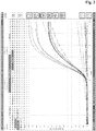
- the result table is combined with real time amplification curves ( Fig. 2 ). As can be seen in Fig. 2 , samples displaying the fluid transfer control status "Pass” do also display positive amplification curves. Samples displaying the fluid transfer control status "Fail” (M-Fail or S-Fail) do display negative amplification curves due to the intended setup of the master mix and target DNA mix combinations.
Landscapes
- Health & Medical Sciences (AREA)
- Physics & Mathematics (AREA)
- Immunology (AREA)
- Chemical & Material Sciences (AREA)
- Analytical Chemistry (AREA)
- Biochemistry (AREA)
- General Health & Medical Sciences (AREA)
- General Physics & Mathematics (AREA)
- Life Sciences & Earth Sciences (AREA)
- Pathology (AREA)
- Chemical Kinetics & Catalysis (AREA)
- Optics & Photonics (AREA)
- Nuclear Medicine, Radiotherapy & Molecular Imaging (AREA)
- Apparatus Associated With Microorganisms And Enzymes (AREA)
- Automatic Analysis And Handling Materials Therefor (AREA)
- Measuring Or Testing Involving Enzymes Or Micro-Organisms (AREA)
Claims (5)
- Fluidtransferkontrollverfahren, wobei das Verfahren umfassta) Bereitstellen einer Lösung, die mit einem Kontrollfarbstoff übertragen werden soll, wobei der Kontrollfarbstoff ein fluoreszierender Farbstoff ist, der an ein Oligonukleotid gebunden ist,b) Übertragen vordefinierter Volumina der Lösung, die eine Konzentration des Kontrollfarbstoffs umfasst, in eine Vielzahl von Gefäßen,c) Messen der Fluoreszenzintensität des Kontrollfarbstoffs in jedem Gefäß,d) Vergleichen der in Schritt c) gemessenen Intensität für jedes Gefäß mit einem vordefinierten Schwellenwert, wobei ein Fluidtransferfehler für ein bestimmtes Gefäß detektiert wird, wenn die in Schritt c) gemessene Intensität unter dem vordefinierten Schwellenwert liegt,e) Ermitteln eines mittleren Intensitätswerts aller Gefäße mit einer in Schritt c) gemessenen Intensität, die über dem vordefinierten Schwellenwert liegt,f) Verifizieren für alle Gefäße mit einer in Schritt c) gemessenen Intensität, die über dem vordefinierten Schwellenwert liegt, ob die Intensität innerhalb eines vordefinierten Bereichs liegt, der den in Schritt e) ermittelten mittleren Intensitätswert umgibt, wobei ein Fluidtransferfehler für ein bestimmtes Gefäß detektiert wird, wenn die in Schritt c) gemessene Intensität nicht innerhalb des Bereichs liegt, undg) Deklarieren eines korrekten Fluidtransfers für alle Gefäße mit einer in Schritt c) gemessenen Intensität, die innerhalb des vordefinierten Bereichs von Schritt f) liegt und wobei vordefinierte Volumina einer zweiten Lösung, die eine Konzentration eines Löschermoleküls umfasst, den Gefäßen zugegeben werden, wobei das Löschermolekül an ein zweites Oligonukleotid gebunden ist, wobei das Oligonukleotid und das zweite Oligonukleotid komplementäre Sequenzen aufweisen, und das Löschermolekül die Intensität des in Schritt a) verwendeten Kontrollfarbstoffs löscht,wobei das Verfahren die zusätzlichen Schritte umfasst vonh) Messen der gelöschten Fluoreszenzintensität des Kontrollfarbstoffs in jedem Gefäß,i) Berechnen eines Löschungsparameterwerts auf Basis der in Schritt h) gemessenen gelöschten Intensität für jedes Gefäß, wobei ein Fluidtransferfehler für ein bestimmtes Gefäß detektiert wird, wenn ein vordefiniertes Löschungs-Schwellenkriterium des Löschungsparameterwerts nicht erfüllt ist,j) Ermitteln eines mittleren Löschungsparameterwerts aller Gefäße mit einem in Schritt i) berechneten Löschungsparameterwert, der das vordefinierte Löschungs-Schwellenkriterium erfüllt,k) Verifizieren für alle Gefäße mit einem in Schritt i) berechneten Löschungsparameterwert, der das vordefinierte Löschungs-Schwellenkriterium erfüllt, ob der Löschungsparameterwert innerhalb eines vordefinierten zweiten Bereichs liegt, der den in Schritt j) ermittelten mittleren Löschungsparameterwert umgibt, wobei ein Fluidtransferfehler für ein bestimmtes Gefäß detektiert wird, wenn der in Schritt i) gemessene Löschungsparameterwert nicht innerhalb des vordefinierten zweiten Bereichs liegt, undl) Deklarieren eines korrekten zweiten Fluidtransfers für alle Gefäße mit einem in Schritt i) gemessenen Löschungsparameterwert, der innerhalb des vordefinierten zweiten Bereichs von Schritt k) liegt, wobei die Vielzahl von Gefäßen als eine Mikrotiterplatte angeordnet ist.
- Fluidtransferkontrollverfahren, wobei das Verfahren umfassta) Bereitstellen einer Lösung, die mit einem Kontrollfarbstoff übertragen werden soll, wobei der Kontrollfarbstoff ein fluoreszierender Farbstoff ist, der an ein Oligonukleotid gebunden ist,b) Übertragen vordefinierter Volumina der Lösung, die eine Konzentration des Kontrollfarbstoffs umfasst, in eine Vielzahl von Gefäßen, und wobei vordefinierte Volumina einer zweiten Lösung, die eine Konzentration eines Löschermoleküls umfasst, den Gefäßen anschließend zugegeben werden, wobei das Löschermolekül an ein zweites Oligonukleotid gebunden ist, wobei das Oligonukleotid und das zweite Oligonukleotid komplementäre Sequenzen aufweisen, und wobei ein Parameter der resultierenden gemischten Lösung derart angepasst wird, dass sich der in Schritt a) verwendete Kontrollfarbstoff in einem nicht gelöschten Zustand befindet,c) Messen der Fluoreszenzintensität des Kontrollfarbstoffs in jedem Gefäß,d) Vergleichen der in Schritt c) gemessenen Intensität für jedes Gefäß mit einem vordefinierten Schwellenwert, wobei ein Fluidtransferfehler für ein bestimmtes Gefäß detektiert wird, wenn die in Schritt c) gemessene Intensität unter dem vordefinierten Schwellenwert liegt,e) Ermitteln eines mittleren Intensitätswerts aller Gefäße mit einer in Schritt c) gemessenen Intensität, die über dem vordefinierten Schwellenwert liegt,f) Verifizieren für alle Gefäße mit einer in Schritt c) gemessenen Intensität, die über dem vordefinierten Schwellenwert liegt, ob die Intensität innerhalb eines vordefinierten Bereichs liegt, der den in Schritt e) ermittelten mittleren Intensitätswert umgibt, wobei ein Fluidtransferfehler für ein bestimmtes Gefäß detektiert wird, wenn die in Schritt c) gemessene Intensität nicht innerhalb des Bereichs liegt, undg) Deklarieren eines korrekten Fluidtransfers für alle Gefäße mit einer in Schritt c) gemessenen Intensität, die innerhalb des vordefinierten Bereichs von Schritt f) liegt und wobei ein Parameter der resultierenden gemischten Lösung derart angepasst wird, dass das Löschermolekül die Intensität des in Schritt a) verwendeten Kontrollfarbstoffs löscht,wobei das Verfahren die zusätzlichen Schritte umfasst vonh) Messen der gelöschten Intensität des Kontrollfarbstoffs in jedem Gefäß,i) Berechnen eines Löschungsparameterwerts auf Basis der in Schritt h) gemessenen gelöschten Intensität für jedes Gefäß, wobei ein Fluidtransferfehler für ein bestimmtes Gefäß detektiert wird, wenn ein vordefiniertes Löschungs-Schwellenkriterium des Löschungsparameterwerts nicht erfüllt ist,j) Ermitteln eines mittleren Löschungsparameterwerts aller Gefäße mit einem in Schritt i) berechneten Löschungsparameterwert, der das vordefinierte Löschungs-Schwellenkriterium erfüllt,k) Verifizieren für alle Gefäße mit einem in Schritt i) berechneten Löschungsparameterwert, der das vordefinierte Löschungs-Schwellenkriterium erfüllt, ob der Löschungsparameterwert innerhalb eines vordefinierten zweiten Bereichs liegt, der den in Schritt j) ermittelten mittleren Löschungsparameterwert umgibt, wobei ein Fluidtransferfehler für ein bestimmtes Gefäß detektiert wird, wenn der in Schritt i) gemessene Löschungsparameterwert nicht innerhalb des vordefinierten zweiten Bereichs liegt, undl) Deklarieren eines korrekten zweiten Fluidtransfers für alle Gefäße mit einem in Schritt i) gemessenen Löschungsparameterwert, der innerhalb des vordefinierten zweiten Bereichs von Schritt k) liegt, und wobei die Vielzahl von Gefäßen als eine Mikrotiterplatte angeordnet ist.
- Fluidtransferkontrollverfahren nach einem der Ansprüche 1 bis 2, wobei der berechnete Löschungsparameterwert von Schritt i) ein Verhältnis der in Schritt c) gemessenen Intensität des Kontrollfarbstoffs und der in Schritt h) gemessenen gelöschten Intensität des Kontrollfarbstoffs ist.
- Fluidtransferkontrollverfahren nach einem der Ansprüche 1 bis 3, wobei das vordefinierte Löschungs-Schwellenkriterium auf Messungen mittels zweier Referenzlösungen basiert, wobei eine erste Referenzlösung das Volumen und die Kontrollfarbstoffkonzentration von Schritt b) aufweist und die zweite Referenzlösung das Volumen und die Löscherfarbstoffkonzentration von Anspruch 1 oder 2 aufweist.
- Fluidtransferkontrollverfahren nach Anspruch 1 zum Herstellen einer anschließenden Echtzeit-PCR-Amplifikation, die einen Detektionsfarbstoff enthält.
Priority Applications (1)
| Application Number | Priority Date | Filing Date | Title |
|---|---|---|---|
| EP10003757.1A EP2239338B1 (de) | 2009-04-09 | 2010-04-08 | Fluidtransferkontrolle |
Applications Claiming Priority (2)
| Application Number | Priority Date | Filing Date | Title |
|---|---|---|---|
| EP09005255 | 2009-04-09 | ||
| EP10003757.1A EP2239338B1 (de) | 2009-04-09 | 2010-04-08 | Fluidtransferkontrolle |
Publications (2)
| Publication Number | Publication Date |
|---|---|
| EP2239338A1 EP2239338A1 (de) | 2010-10-13 |
| EP2239338B1 true EP2239338B1 (de) | 2017-06-28 |
Family
ID=40902683
Family Applications (1)
| Application Number | Title | Priority Date | Filing Date |
|---|---|---|---|
| EP10003757.1A Active EP2239338B1 (de) | 2009-04-09 | 2010-04-08 | Fluidtransferkontrolle |
Country Status (6)
| Country | Link |
|---|---|
| US (1) | US8906306B2 (de) |
| EP (1) | EP2239338B1 (de) |
| JP (1) | JP5394974B2 (de) |
| CN (1) | CN101857898A (de) |
| CA (1) | CA2699011C (de) |
| ES (1) | ES2638769T3 (de) |
Families Citing this family (5)
| Publication number | Priority date | Publication date | Assignee | Title |
|---|---|---|---|---|
| FI20096013A7 (fi) | 2009-10-02 | 2011-04-03 | Finnzymes Oy | Menetelmä reaktioseoksen valmistelemiseksi ja tähän liittyvät tuotteet |
| US12065698B2 (en) | 2009-10-02 | 2024-08-20 | Thermo Fisher Scientific Baltics Uab | Sample processing apparatus and method |
| WO2012131167A1 (en) * | 2011-04-01 | 2012-10-04 | Finnzymes Oy | Sample processing apparatus and method |
| EP2574931B1 (de) | 2011-09-29 | 2017-03-22 | Qiagen GmbH | Trockenzusammensetzung mit einem Steuerfarbstoff |
| US20160053302A1 (en) * | 2014-04-22 | 2016-02-25 | Roche Molecular Systems, Inc. | Method for visual identification of pcr solutions for accurate reaction setup |
Family Cites Families (20)
| Publication number | Priority date | Publication date | Assignee | Title |
|---|---|---|---|---|
| JPH02195256A (ja) * | 1989-01-24 | 1990-08-01 | Matsushita Electric Ind Co Ltd | 免疫的検出方法および装置 |
| US5061639A (en) * | 1989-12-06 | 1991-10-29 | E. I. Dupont De Nemours And Company | Liquid dispenser accuracy verification method |
| US5736333A (en) * | 1996-06-04 | 1998-04-07 | The Perkin-Elmer Corporation | Passive internal references for the detection of nucleic acid amplification products |
| JP4763160B2 (ja) | 2001-06-18 | 2011-08-31 | 日立アロカメディカル株式会社 | 分注良否判定装置 |
| DE10212557A1 (de) * | 2002-03-14 | 2003-09-25 | Univ Schiller Jena | Verfahren zur Charakterisierung hochparallelisierter Liquidhandlingtechnik mittels Mikroplatten sowie Testkit zur Durchführung des Verfahrens |
| JP2004016132A (ja) | 2002-06-18 | 2004-01-22 | Canon Inc | 核酸の測定方法、及びその方法によって得られるデータ解析法 |
| EP1389638A1 (de) | 2002-08-06 | 2004-02-18 | Roche Diagnostics GmbH | Verbesserte Proben für FRET |
| DE10248555B4 (de) * | 2002-10-18 | 2004-12-02 | Roche Diagnostics Gmbh | Verfahren und Analysesystem zur Ermittlung der Konzentration eines Analyten in einer Probe, die aus dem Analyten und der Probenmatrix besteht und Testelement dafür |
| JP2004325422A (ja) * | 2003-04-30 | 2004-11-18 | Institute Of Physical & Chemical Research | マイクロアレイ作製方法、マイクロアレイ作製用ヘッドおよび装置 |
| US20050232818A1 (en) * | 2003-09-19 | 2005-10-20 | Donald Sandell | Single sheet seal applicator and cartridge |
| JP2006010491A (ja) | 2004-06-25 | 2006-01-12 | Mitsubishi Kagaku Bio-Clinical Laboratories Inc | 体液分析方法及び分注良否判定装置 |
| US7964413B2 (en) | 2005-03-10 | 2011-06-21 | Gen-Probe Incorporated | Method for continuous mode processing of multiple reaction receptacles in a real-time amplification assay |
| JP2007017382A (ja) | 2005-07-11 | 2007-01-25 | Olympus Corp | マイクロアレイの製造方法および製造装置 |
| JP2007046979A (ja) | 2005-08-09 | 2007-02-22 | Juki Corp | 分注量の自動補正方法及びその機能を有する分注装置 |
| CN101505873B (zh) | 2005-08-24 | 2011-12-28 | 泰利化学公司 | 测试液体样品的方法、测试装置和多个测试装置的自动化系统 |
| DE502005008153D1 (de) | 2005-11-23 | 2009-10-29 | Roche Diagnostics Gmbh | Polynukleotid mit Phosphatmimetikum |
| US8003405B2 (en) * | 2005-12-16 | 2011-08-23 | Artel, Inc. | Calibrating dispensing device performance for complex and/or non-aqueous liquids |
| JP5179376B2 (ja) * | 2005-12-19 | 2013-04-10 | エシコン・インコーポレイテッド | ローラーボトルでの分娩後取り出し細胞の体外増殖 |
| WO2007146443A2 (en) * | 2006-06-14 | 2007-12-21 | Oldenburg Kevin R Ph D | Thermal-cycling devices and methods of using the same |
| US20080201103A1 (en) * | 2007-01-30 | 2008-08-21 | Applera Corporation | Robust Detection of Variability in Multiple Sets of Data |
-
2010
- 2010-03-29 US US12/748,688 patent/US8906306B2/en active Active
- 2010-04-06 CA CA2699011A patent/CA2699011C/en active Active
- 2010-04-08 JP JP2010089742A patent/JP5394974B2/ja active Active
- 2010-04-08 EP EP10003757.1A patent/EP2239338B1/de active Active
- 2010-04-08 ES ES10003757.1T patent/ES2638769T3/es active Active
- 2010-04-08 CN CN201010161878A patent/CN101857898A/zh active Pending
Also Published As
| Publication number | Publication date |
|---|---|
| CA2699011C (en) | 2017-06-20 |
| JP5394974B2 (ja) | 2014-01-22 |
| CA2699011A1 (en) | 2010-10-09 |
| CN101857898A (zh) | 2010-10-13 |
| ES2638769T3 (es) | 2017-10-24 |
| EP2239338A1 (de) | 2010-10-13 |
| US20110086337A1 (en) | 2011-04-14 |
| JP2010243497A (ja) | 2010-10-28 |
| US8906306B2 (en) | 2014-12-09 |
Similar Documents
| Publication | Publication Date | Title |
|---|---|---|
| JP4022600B2 (ja) | 核酸増幅効率の決定方法 | |
| EP2239338B1 (de) | Fluidtransferkontrolle | |
| US7920971B2 (en) | Quantification schemes for quantifying nucleic acids | |
| CN108369180B (zh) | 用于分析样品和监测光信号检测器的性能的系统和方法 | |
| KR102300738B1 (ko) | 타겟 분석물질에 대한 데이터 세트의 노이즈 수준 감축 방법 | |
| Yuan et al. | Droplet digital PCR for quantification of PML-RARα in acute promyelocytic leukemia: a comprehensive comparison with real-time PCR | |
| CA3108364A1 (en) | Method for carrying out real-time pcr | |
| CN112513291B (zh) | 用于进行定量实时pcr的反应混合物、方法和试剂盒 | |
| KR102662580B1 (ko) | 변이 유전자 검출 방법 | |
| JP2014023435A (ja) | 核酸増幅分析装置及び核酸増幅分析方法 | |
| Pinhasov et al. | Gene expression analysis for high throughput screening applications | |
| US8293473B2 (en) | Assessment of reaction kinetics compatibility between polymerase chain reactions | |
| EP4454758A1 (de) | Kontrollen für nukleinsäureamplifikationsverfahren | |
| US20240076751A1 (en) | Variant classification through high-confidence mutation detection from fluorescence signals measured with a multiple mutation assay | |
| Liang et al. | Application of traditional clinical pathology quality control techniques to molecular pathology | |
| Fedele et al. | Development and validation of automated methods for COVID-19 PCR Master Mix preparation | |
| US12060616B2 (en) | Method for assisting determination of hematological stage of childhood acute lymphoblastic leukemia | |
| EP4722384A1 (de) | Dpcr mit erweitertem dynamikbereich | |
| US20250246264A1 (en) | Method of guiding at least two detailed performance experiments required for developing reagent for detecting target nucleic acid molecule, and organizing an experiment result documentation | |
| JP2023507597A (ja) | 流体中に含まれるdna配列のコピー数を算定する方法及び装置 | |
| Hoebeeck et al. | Real-Time PCR Quality Control for Gene Expression Profiling Using the LightCycler® 480 System | |
| Spas et al. | Internal validation of a DNA quantification method using the quantifiler® human DNA quantification kit and the 7500 real-time PCR system with the hid real-time PCR analysis software V 1.1 at the biology department of the central forensic laboratory of the police. Forensic practice | |
| JP4597078B2 (ja) | 自動分析装置 | |
| JRC | Event-specific method for the quantitation of rice line LLRICE62 using real-time PCR | |
| WO2005114574A2 (en) | System for the detection and the quantification of exogenous dna of animal origin in edible flours |
Legal Events
| Date | Code | Title | Description |
|---|---|---|---|
| PUAI | Public reference made under article 153(3) epc to a published international application that has entered the european phase |
Free format text: ORIGINAL CODE: 0009012 |
|
| AK | Designated contracting states |
Kind code of ref document: A1 Designated state(s): AT BE BG CH CY CZ DE DK EE ES FI FR GB GR HR HU IE IS IT LI LT LU LV MC MK MT NL NO PL PT RO SE SI SK SM TR |
|
| AX | Request for extension of the european patent |
Extension state: AL BA ME RS |
|
| 17P | Request for examination filed |
Effective date: 20110413 |
|
| RIC1 | Information provided on ipc code assigned before grant |
Ipc: G01N 21/64 20060101ALI20161028BHEP Ipc: G01N 21/84 20060101ALI20161028BHEP Ipc: C12Q 1/68 20060101AFI20161028BHEP Ipc: G01N 35/10 20060101ALI20161028BHEP |
|
| GRAP | Despatch of communication of intention to grant a patent |
Free format text: ORIGINAL CODE: EPIDOSNIGR1 |
|
| INTG | Intention to grant announced |
Effective date: 20170126 |
|
| GRAS | Grant fee paid |
Free format text: ORIGINAL CODE: EPIDOSNIGR3 |
|
| GRAA | (expected) grant |
Free format text: ORIGINAL CODE: 0009210 |
|
| AK | Designated contracting states |
Kind code of ref document: B1 Designated state(s): AT BE BG CH CY CZ DE DK EE ES FI FR GB GR HR HU IE IS IT LI LT LU LV MC MK MT NL NO PL PT RO SE SI SK SM TR |
|
| REG | Reference to a national code |
Ref country code: GB Ref legal event code: FG4D |
|
| REG | Reference to a national code |
Ref country code: CH Ref legal event code: EP |
|
| REG | Reference to a national code |
Ref country code: AT Ref legal event code: REF Ref document number: 904868 Country of ref document: AT Kind code of ref document: T Effective date: 20170715 |
|
| REG | Reference to a national code |
Ref country code: IE Ref legal event code: FG4D |
|
| REG | Reference to a national code |
Ref country code: DE Ref legal event code: R096 Ref document number: 602010043216 Country of ref document: DE |
|
| REG | Reference to a national code |
Ref country code: ES Ref legal event code: FG2A Ref document number: 2638769 Country of ref document: ES Kind code of ref document: T3 Effective date: 20171024 |
|
| PG25 | Lapsed in a contracting state [announced via postgrant information from national office to epo] |
Ref country code: NO Free format text: LAPSE BECAUSE OF FAILURE TO SUBMIT A TRANSLATION OF THE DESCRIPTION OR TO PAY THE FEE WITHIN THE PRESCRIBED TIME-LIMIT Effective date: 20170928 Ref country code: GR Free format text: LAPSE BECAUSE OF FAILURE TO SUBMIT A TRANSLATION OF THE DESCRIPTION OR TO PAY THE FEE WITHIN THE PRESCRIBED TIME-LIMIT Effective date: 20170929 Ref country code: LT Free format text: LAPSE BECAUSE OF FAILURE TO SUBMIT A TRANSLATION OF THE DESCRIPTION OR TO PAY THE FEE WITHIN THE PRESCRIBED TIME-LIMIT Effective date: 20170628 Ref country code: HR Free format text: LAPSE BECAUSE OF FAILURE TO SUBMIT A TRANSLATION OF THE DESCRIPTION OR TO PAY THE FEE WITHIN THE PRESCRIBED TIME-LIMIT Effective date: 20170628 Ref country code: FI Free format text: LAPSE BECAUSE OF FAILURE TO SUBMIT A TRANSLATION OF THE DESCRIPTION OR TO PAY THE FEE WITHIN THE PRESCRIBED TIME-LIMIT Effective date: 20170628 |
|
| REG | Reference to a national code |
Ref country code: NL Ref legal event code: MP Effective date: 20170628 |
|
| REG | Reference to a national code |
Ref country code: LT Ref legal event code: MG4D |
|
| REG | Reference to a national code |
Ref country code: AT Ref legal event code: MK05 Ref document number: 904868 Country of ref document: AT Kind code of ref document: T Effective date: 20170628 |
|
| PG25 | Lapsed in a contracting state [announced via postgrant information from national office to epo] |
Ref country code: NL Free format text: LAPSE BECAUSE OF FAILURE TO SUBMIT A TRANSLATION OF THE DESCRIPTION OR TO PAY THE FEE WITHIN THE PRESCRIBED TIME-LIMIT Effective date: 20170628 Ref country code: SE Free format text: LAPSE BECAUSE OF FAILURE TO SUBMIT A TRANSLATION OF THE DESCRIPTION OR TO PAY THE FEE WITHIN THE PRESCRIBED TIME-LIMIT Effective date: 20170628 Ref country code: LV Free format text: LAPSE BECAUSE OF FAILURE TO SUBMIT A TRANSLATION OF THE DESCRIPTION OR TO PAY THE FEE WITHIN THE PRESCRIBED TIME-LIMIT Effective date: 20170628 Ref country code: BG Free format text: LAPSE BECAUSE OF FAILURE TO SUBMIT A TRANSLATION OF THE DESCRIPTION OR TO PAY THE FEE WITHIN THE PRESCRIBED TIME-LIMIT Effective date: 20170928 |
|
| PG25 | Lapsed in a contracting state [announced via postgrant information from national office to epo] |
Ref country code: EE Free format text: LAPSE BECAUSE OF FAILURE TO SUBMIT A TRANSLATION OF THE DESCRIPTION OR TO PAY THE FEE WITHIN THE PRESCRIBED TIME-LIMIT Effective date: 20170628 Ref country code: CZ Free format text: LAPSE BECAUSE OF FAILURE TO SUBMIT A TRANSLATION OF THE DESCRIPTION OR TO PAY THE FEE WITHIN THE PRESCRIBED TIME-LIMIT Effective date: 20170628 Ref country code: RO Free format text: LAPSE BECAUSE OF FAILURE TO SUBMIT A TRANSLATION OF THE DESCRIPTION OR TO PAY THE FEE WITHIN THE PRESCRIBED TIME-LIMIT Effective date: 20170628 Ref country code: AT Free format text: LAPSE BECAUSE OF FAILURE TO SUBMIT A TRANSLATION OF THE DESCRIPTION OR TO PAY THE FEE WITHIN THE PRESCRIBED TIME-LIMIT Effective date: 20170628 Ref country code: SK Free format text: LAPSE BECAUSE OF FAILURE TO SUBMIT A TRANSLATION OF THE DESCRIPTION OR TO PAY THE FEE WITHIN THE PRESCRIBED TIME-LIMIT Effective date: 20170628 |
|
| PG25 | Lapsed in a contracting state [announced via postgrant information from national office to epo] |
Ref country code: IS Free format text: LAPSE BECAUSE OF FAILURE TO SUBMIT A TRANSLATION OF THE DESCRIPTION OR TO PAY THE FEE WITHIN THE PRESCRIBED TIME-LIMIT Effective date: 20171028 Ref country code: PL Free format text: LAPSE BECAUSE OF FAILURE TO SUBMIT A TRANSLATION OF THE DESCRIPTION OR TO PAY THE FEE WITHIN THE PRESCRIBED TIME-LIMIT Effective date: 20170628 Ref country code: SM Free format text: LAPSE BECAUSE OF FAILURE TO SUBMIT A TRANSLATION OF THE DESCRIPTION OR TO PAY THE FEE WITHIN THE PRESCRIBED TIME-LIMIT Effective date: 20170628 |
|
| REG | Reference to a national code |
Ref country code: FR Ref legal event code: PLFP Year of fee payment: 9 |
|
| REG | Reference to a national code |
Ref country code: DE Ref legal event code: R097 Ref document number: 602010043216 Country of ref document: DE |
|
| PG25 | Lapsed in a contracting state [announced via postgrant information from national office to epo] |
Ref country code: DK Free format text: LAPSE BECAUSE OF FAILURE TO SUBMIT A TRANSLATION OF THE DESCRIPTION OR TO PAY THE FEE WITHIN THE PRESCRIBED TIME-LIMIT Effective date: 20170628 |
|
| PLBE | No opposition filed within time limit |
Free format text: ORIGINAL CODE: 0009261 |
|
| STAA | Information on the status of an ep patent application or granted ep patent |
Free format text: STATUS: NO OPPOSITION FILED WITHIN TIME LIMIT |
|
| 26N | No opposition filed |
Effective date: 20180329 |
|
| PG25 | Lapsed in a contracting state [announced via postgrant information from national office to epo] |
Ref country code: SI Free format text: LAPSE BECAUSE OF FAILURE TO SUBMIT A TRANSLATION OF THE DESCRIPTION OR TO PAY THE FEE WITHIN THE PRESCRIBED TIME-LIMIT Effective date: 20170628 |
|
| PG25 | Lapsed in a contracting state [announced via postgrant information from national office to epo] |
Ref country code: MC Free format text: LAPSE BECAUSE OF FAILURE TO SUBMIT A TRANSLATION OF THE DESCRIPTION OR TO PAY THE FEE WITHIN THE PRESCRIBED TIME-LIMIT Effective date: 20170628 |
|
| REG | Reference to a national code |
Ref country code: BE Ref legal event code: MM Effective date: 20180430 |
|
| REG | Reference to a national code |
Ref country code: IE Ref legal event code: MM4A |
|
| PG25 | Lapsed in a contracting state [announced via postgrant information from national office to epo] |
Ref country code: LU Free format text: LAPSE BECAUSE OF NON-PAYMENT OF DUE FEES Effective date: 20180408 |
|
| PG25 | Lapsed in a contracting state [announced via postgrant information from national office to epo] |
Ref country code: BE Free format text: LAPSE BECAUSE OF NON-PAYMENT OF DUE FEES Effective date: 20180430 |
|
| PG25 | Lapsed in a contracting state [announced via postgrant information from national office to epo] |
Ref country code: IE Free format text: LAPSE BECAUSE OF NON-PAYMENT OF DUE FEES Effective date: 20180408 |
|
| PG25 | Lapsed in a contracting state [announced via postgrant information from national office to epo] |
Ref country code: MT Free format text: LAPSE BECAUSE OF NON-PAYMENT OF DUE FEES Effective date: 20180408 |
|
| PG25 | Lapsed in a contracting state [announced via postgrant information from national office to epo] |
Ref country code: TR Free format text: LAPSE BECAUSE OF FAILURE TO SUBMIT A TRANSLATION OF THE DESCRIPTION OR TO PAY THE FEE WITHIN THE PRESCRIBED TIME-LIMIT Effective date: 20170628 |
|
| PG25 | Lapsed in a contracting state [announced via postgrant information from national office to epo] |
Ref country code: PT Free format text: LAPSE BECAUSE OF FAILURE TO SUBMIT A TRANSLATION OF THE DESCRIPTION OR TO PAY THE FEE WITHIN THE PRESCRIBED TIME-LIMIT Effective date: 20170628 Ref country code: HU Free format text: LAPSE BECAUSE OF FAILURE TO SUBMIT A TRANSLATION OF THE DESCRIPTION OR TO PAY THE FEE WITHIN THE PRESCRIBED TIME-LIMIT; INVALID AB INITIO Effective date: 20100408 |
|
| PG25 | Lapsed in a contracting state [announced via postgrant information from national office to epo] |
Ref country code: CY Free format text: LAPSE BECAUSE OF FAILURE TO SUBMIT A TRANSLATION OF THE DESCRIPTION OR TO PAY THE FEE WITHIN THE PRESCRIBED TIME-LIMIT Effective date: 20170628 Ref country code: MK Free format text: LAPSE BECAUSE OF NON-PAYMENT OF DUE FEES Effective date: 20170628 |
|
| PGFP | Annual fee paid to national office [announced via postgrant information from national office to epo] |
Ref country code: DE Payment date: 20250319 Year of fee payment: 16 |
|
| PGFP | Annual fee paid to national office [announced via postgrant information from national office to epo] |
Ref country code: ES Payment date: 20250502 Year of fee payment: 16 |
|
| PGFP | Annual fee paid to national office [announced via postgrant information from national office to epo] |
Ref country code: CH Payment date: 20250501 Year of fee payment: 16 |
|
| PGFP | Annual fee paid to national office [announced via postgrant information from national office to epo] |
Ref country code: GB Payment date: 20260319 Year of fee payment: 17 |
|
| PGFP | Annual fee paid to national office [announced via postgrant information from national office to epo] |
Ref country code: IT Payment date: 20260319 Year of fee payment: 17 |
|
| PGFP | Annual fee paid to national office [announced via postgrant information from national office to epo] |
Ref country code: FR Payment date: 20260320 Year of fee payment: 17 |