EP2236747B1 - Systeme, Verfahren und Vorrichtung zur passiven Reinigungsströmungssteuerung in Turbinen - Google Patents
Systeme, Verfahren und Vorrichtung zur passiven Reinigungsströmungssteuerung in Turbinen Download PDFInfo
- Publication number
- EP2236747B1 EP2236747B1 EP10156534.9A EP10156534A EP2236747B1 EP 2236747 B1 EP2236747 B1 EP 2236747B1 EP 10156534 A EP10156534 A EP 10156534A EP 2236747 B1 EP2236747 B1 EP 2236747B1
- Authority
- EP
- European Patent Office
- Prior art keywords
- rotor
- wheels
- turbine
- stator
- air flow
- Prior art date
- Legal status (The legal status is an assumption and is not a legal conclusion. Google has not performed a legal analysis and makes no representation as to the accuracy of the status listed.)
- Not-in-force
Links
Images


Classifications
-
- F—MECHANICAL ENGINEERING; LIGHTING; HEATING; WEAPONS; BLASTING
- F01—MACHINES OR ENGINES IN GENERAL; ENGINE PLANTS IN GENERAL; STEAM ENGINES
- F01D—NON-POSITIVE DISPLACEMENT MACHINES OR ENGINES, e.g. STEAM TURBINES
- F01D5/00—Blades; Blade-carrying members; Heating, heat-insulating, cooling or antivibration means on the blades or the members
- F01D5/02—Blade-carrying members, e.g. rotors
- F01D5/08—Heating, heat-insulating or cooling means
- F01D5/085—Heating, heat-insulating or cooling means cooling fluid circulating inside the rotor
-
- F—MECHANICAL ENGINEERING; LIGHTING; HEATING; WEAPONS; BLASTING
- F01—MACHINES OR ENGINES IN GENERAL; ENGINE PLANTS IN GENERAL; STEAM ENGINES
- F01D—NON-POSITIVE DISPLACEMENT MACHINES OR ENGINES, e.g. STEAM TURBINES
- F01D11/00—Preventing or minimising internal leakage of working-fluid, e.g. between stages
- F01D11/001—Preventing or minimising internal leakage of working-fluid, e.g. between stages for sealing space between stator blade and rotor
-
- F—MECHANICAL ENGINEERING; LIGHTING; HEATING; WEAPONS; BLASTING
- F01—MACHINES OR ENGINES IN GENERAL; ENGINE PLANTS IN GENERAL; STEAM ENGINES
- F01D—NON-POSITIVE DISPLACEMENT MACHINES OR ENGINES, e.g. STEAM TURBINES
- F01D5/00—Blades; Blade-carrying members; Heating, heat-insulating, cooling or antivibration means on the blades or the members
- F01D5/02—Blade-carrying members, e.g. rotors
- F01D5/06—Rotors for more than one axial stage, e.g. of drum or multiple disc type; Details thereof, e.g. shafts, shaft connections
- F01D5/066—Connecting means for joining rotor-discs or rotor-elements together, e.g. by a central bolt, by clamps
-
- F—MECHANICAL ENGINEERING; LIGHTING; HEATING; WEAPONS; BLASTING
- F02—COMBUSTION ENGINES; HOT-GAS OR COMBUSTION-PRODUCT ENGINE PLANTS
- F02C—GAS-TURBINE PLANTS; AIR INTAKES FOR JET-PROPULSION PLANTS; CONTROLLING FUEL SUPPLY IN AIR-BREATHING JET-PROPULSION PLANTS
- F02C7/00—Features, components parts, details or accessories, not provided for in, or of interest apart form groups F02C1/00 - F02C6/00; Air intakes for jet-propulsion plants
- F02C7/12—Cooling of plants
- F02C7/16—Cooling of plants characterised by cooling medium
- F02C7/18—Cooling of plants characterised by cooling medium the medium being gaseous, e.g. air
Definitions
- Embodiments of the invention relate generally to turbines and more specifically, to systems, methods, and apparatus for passive purge flow control in a turbine.
- Turbines typically comprise a rotating part such as the rotor, and a stationary part such as a stator.
- the rotor of a turbine may include a plurality of stacked wheels.
- the outer radial region of the stacked wheels is known as rim portion while the central radial region of the stacked wheels is known as the bore portion.
- Typical operation of turbines involves high temperatures which can subject the various components of the turbine to relatively extreme thermal loads.
- the rim portion of a rotor of a gas turbine is typically exposed to a high temperature gas flow, and therefore, is heated to relatively high temperatures compared to the bore portion of the rotor during start up, thus generating a significant radial thermal gradient between the rim and the bore of the rotor. This rim-to-bore thermal gradient causes stress cycling during startup and shutdown cycle of gas turbine and thereby adversely affects the life of the mechanical components of the turbine.
- a plurality of solid and annular wheels are placed in adjacent positions, and are secured to one another by a plurality of axially extending bolts and rabbeted joints provided between the adjacent wheels.
- differential heating of the wheels can cause significant rotor bore stresses and deflections which tend to open up the rabbeted joints.
- the thermal conditions of the rotor and the associated wheels are different at startup, steady state operation, and turbine shutdown.
- the rim portion of the turbine wheels are typically in direct contact with the hot turbine flow path , and therefore, the rim portion tends to heat up faster than the bore portion, resulting in a relatively high temperature gradient.
- WO 1997/44575 describes convective cooling of turbine hot parts using a closed loop system which is applied to cooling the hot parts of combustion turbine power plants, where the cooling provided permits an increase in the inlet temperature and the concomitant benefits of increased efficiency and output.
- Air is removed from the combustion turbine compressor and delivered to passages internal to one or more of a combustor and turbine hot parts. The air cools the combustor and turbine hot parts via convection and heat is transferred through the surfaces of the combustor and turbine hot parts.
- US 5695319 describes a vapor cooled gas turbine having a cooling system including a vapor supply port and a vapor recovery port, and the cooling system is formed so that vapor from the supply port is supplied to blades through a central supply passage in a rotor and the vapor having cooled the blades is recovered from the recovery port through a recovery passage spaced outwardly from the supply passage
- the invention resides in a method for control of radial temperature gradients in a rotor of a gas turbine as defined in claim 1 and in a system for controlling radial temperature gradients in a rotor of a gas turbine as defined in claim 5.
- Various embodiments of the invention may include a sealing device for controlling air flow to at least one inlet hole on the rotor, operable to purge air to reduce the radial temperature gradients in the rotor.
- the purge air may heat up the bore of turbine wheels during startup of the gas turbine and subsequently cool the bore of turbine wheels during shutdown of the turbine.
- Flow control through the sealing device may be achieved based at least in part on axial deflection between the rotor and an associated stator during operation of the gas turbine.
- compressor discharge air may also be provided to the rotor bore and into the cavities between the turbine wheels of the rotor through an air flow path where the air flow path may include the inlet hole on the rotor and a plurality of holes in the turbine wheels of the rotor.
- At least one technical effect of certain embodiments of the invention described herein is that an air flow path can be provided to the bore of a turbine rotor to control the radial temperature gradients in the rotor.
- This arrangement can improve the performance of the turbine by eliminating or otherwise minimizing the losses associated with the use of purged air for cooling/heating the rotor bore during steady state operation.
- the sealing device used for controlling the flow of purged air can use the relative axial movement between the rotor and stator parts, wherein such movement occurs during operation of the turbine.
- the design of the sealing device can ensure that the air flow is neither disturbed or otherwise is relatively unaffected due to the presence of the sealing device, thus ensuring minimal flow losses and relatively smooth flow through the turbine section. Therefore, the use of the sealing device to control the purge flow may have the technical effect of improving the performance of the turbine.
- FIG. 1 is a diagram illustrating one example of a change in the rim-to-bore temperature gradient associated with a rotor of a gas turbine according to an illustrative embodiment of the invention.
- FIG. 1 shows a plot 100 representative of an example variance in the rim to bore temperature gradient of a turbine wheel during transient and subsequently steady state operation of the gas turbine.
- the horizontal axis may represent duration (in seconds) of operation of the gas turbine.
- the operation duration of the gas turbine may include the time of transient operation such as startup duration, and the time of subsequent full load operation of the gas turbine.
- the vertical axis may represent the radial rim-to-bore temperature gradient (in degrees Fahrenheit) in the turbine wheels of the rotor.
- the plot 100 shows a gradual rise in the rim-to-bore temperature gradient during the transient operation, such as in the startup period of the gas turbine. Subsequently, the curve attains a peak midway during the startup duration, at around approximately 1500 seconds and then falls off gradually as the gas turbine attains steady state or near steady state operation. In various embodiments of the invention, the nature of the curve in the startup duration may also be representative of the system behavior during shutdown of the gas turbine engine.
- the plot 100 shown in FIG. 1 remains relatively flat during the steady state or near steady state operation of the gas turbine signifying virtually no or little change in the rim-to-bore temperature beyond the full load point as the gas turbine approaches steady state or near steady state operation.
- high rim-to-bore temperature gradients for a turbine wheel are controlled by using purge flows directed to the bore of the rotor during some or all of the operational cycle of the gas turbine.
- the efficiency of the turbine may be increased by suitably controlling the purge flow during different stages of operation of the turbine. Since, as shown in FIG. 1 , the rim-to-bore temperature gradient settles to an acceptable value after full load time point, there is little or no requirement of purge air during the steady state or near steady state operation of the gas turbine. Air purged into the bore of the rotor during the steady state or near steady state operation keeps circulating in the turbine section thus affecting the efficiency of the turbine.
- purge flow may be required during shutdown of the turbine as temperature gradients can develop between the rim and the bore region owing to the relatively rapid cooling of the rim portion compared to the bore portion.
- An arrangement described as shown in FIG. 2 can be operable to control the purge flow directed to the bore of the rotor during different operational stages of the turbine, and hence may ensure relatively efficient use of the purge air.
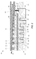
- FIG. 2 is a magnified cross-sectional side view of one example compressor section 200 of a gas turbine that may be utilized in accordance with various embodiments of the invention.
- FIG. 2 illustrates an example environment of one example compressor section 200 of a gas turbine. Additionally or alternatively, other embodiments of the invention may include a turbine section of a gas turbine as the example environment.
- the example compressor section 200 illustrated in FIG. 2 may include two primary structures: a rotating structure 202 such as a rotor, and a static structure such as a stator 204.
- a plurality of stacked wheels (hereinafter referred to as turbine wheels) mounted on and forming part of the rotor 202, may include a plurality of solid wheels 206 arranged alternately between a plurality of annular wheels 208.
- Each turbine wheel further includes a plurality of buckets 210 (rotor blades) projecting radially outward from the rotor 202 while a plurality of nozzles 212 (stator blades) mounted on the stator 204 and projecting radially inward towards the rotor 202, may be positioned alternately between the buckets 210.
- the plurality of rotor blades 210 and the stator blades 212 form a passage through which the air in compressor section 200 flows. Consequently, rim 214 of the rotor 202 is exposed to the hot gas path while bore 216 remains shielded from the hot gas flow, and forms the root of the rotor 202 touching the centerline axis 218. Thus a radial temperature gradient can exist between the rim 214 and the bore 216 of the rotor 202 which may lead to relatively extreme thermal stresses.
- the bore 216 of the rotor 202 may be heated during the startup of the gas turbine, while during shutdown of the engine; the bore 216 may be cooled to reduce the radial temperature gradient between the rim 214 and the bore 216.
- an air flow path 220 may be provided from the hot gas flow path in the compressor section 200 to the bore 216, through the aft end of the rotor 202.
- the air flow path 220 may include at least one inlet hole 222 on a rotor structure, through which the air flow may be controlled by a sealing device 224.
- the air flow path 220 may further connect the inlet hole 222 to a plurality of holes 226 in at least some of the turbine wheels.
- the air from the hot gas path may be directed in the bore 216 through a path around the annular wheels 208 and through the plurality of holes 226 in the solid wheels 206.
- the portion of the purge air that follows the air flow path 220 may be derived from the compressor main air-flow path 230.
- the remaining portions of the main air may either go to combustor and the turbine section 232 or to cool/purge the turbine section 234.
- the plurality of holes 226 which allow air flow to pass through the solid bore wheels 206 may be along or at an angle to the engine centerline axis 218. Additionally, in at least one embodiment, the plurality of holes 226 in the solid wheels 206 may be located between approximately 0.2*R and approximately 0.65*R from the central axis 218 of each wheel, where R is the rim radius of the solid wheels 206.
- the at least one inlet hole 222 which forms part of the air path 220 may be in flow communication with a cavity defined within the rotor 202, while the cavity may in turn be in flow communication with the plurality of holes 226 in the solid turbine wheels 206.
- the air flow path 220 thus directs flow from the hot gas path to the bore 216 through the inlet hole 222. Subsequently the air flow path 220 passes through the holes 226 in the solid wheels 206 and around the annular wheels 208 positioned alternately in between the solid wheels, thus forming a curved flow path known as a serpentine flow path.
- the serpentine flow path formed in the bore region of the rotor 202 can expose a relatively larger surface area along the length of the turbine wheels to the air flow.
- the increased exposure of the surface to the air flow leads to relatively more effective heating or cooling of the compressor wheel bore surface.
- the serpentine path can serve to more effectively reduce the radial temperature gradient between the rim 214 and the bore 216 of the rotor 202 during transient operation of the gas turbine.
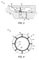
- FIG. 3 is a magnified cross-sectional side view of a part of a turbine section 300 in which control of purge flow may be achieved, in accordance with an embodiment of the invention.
- FIG. 3 shows an example sealing device 224 operable to control purge flow, in accordance with an embodiment of the invention.
- FIG. 3 illustrates a part of a turbine section 300 where the sealing device 224 is operable to control the purge flow through the inlet hole 222.
- the example sealing device 224 may be cantilevered from a plurality of circumferential locations on the stator 204.
- the sealing device 224 which is operable to control the purge flow, may include a plurality of spokes 302 cantilevered from the stator 204, with bristles 304 at the end which rub against the rotor 202.
- the bristles 304 may be mounted on the inner circumference of a sealing hub 308 which is supported by the plurality of spokes 302 at different circumferential positions.
- the sealing device 224 may be an axial-shaped ring with an axial width X1 of approximately 0.06 inches.
- the sealing device 224 may be of any shape and may not be limited to an axial-shaped ring.
- the bristles 304 may be mounted at one end within a bristle pack 306, that may be mounted to the sealing hub 308.
- the bristle pack 306 may secure a ring of densely packed metal wires, or bristles 304.
- the bristles 304 may be arranged at an angle in the direction of rotation of rotor. Bristle length can be around 1 inch, or 2.5 cm.
- the rotor parts may undergo an axial deflection with respect to the stator parts due to a combination of temperature differential, associated thermal expansion, and load stresses.
- the relative axial deflection between the rotor and the stator parts is observed during startup and shutdown of the turbine.
- the transiently varying relative deflection however reaches a maximum during the full load time, and remains constant during the entire duration of the steady state or near steady state operation of the turbine.
- the sealing device 224 held from the stator 204 may be positioned so that it does not block the at least one inlet hole 222, and heated air may flow to the bore portion.
- the sealing device 224 held from the stator 204 may relatively move with respect to the rotor 202 and begin to cover and block at least a portion of the at least one inlet hole 222, thereby restricting the flow of the heated air to the bore region.
- the sealing device 224 may stop moving with respect to the rotor 202, and may continue to cover all or part of the inlet hole 222.
- the reversed relative axial deflection between the stator and rotor parts may allow the sealing device 224 to uncover at least part of the one inlet hole 222.
- the differential axial deflection between the rotor and the stator parts may be between approximately 0.1 to approximately 0.2 inches after startup and during steady state operation.
- the width X1 of the sealing device 224 bristles 304 may be approximately 0.04 to approximately 0.1 inches, and the first end of the sealing device 224 may be placed at a distance X2 of approximately 0.1 to approximately 0.2 inches from the inlet hole 222 before the gas turbine is started.
- the width X1 of the sealing device 224 and bristles 304 may be approximately 0.06 inches, and the first end of the sealing device 224 may be placed at a distance X2 of approximately 0.18 inches from the first edge of the inlet hole 222.
- FIG. 4 is an enlarged front view of the example sealing device 224 in accordance with an embodiment of the invention.
- FIG. 4 illustrates the front view 400 of the sealing device 224 shown in figures 2 and 3 .
- the example sealing device 224 shown in FIG. 4 includes one or more bristles 304 mounted within a bristle pack 306, and the bristle pack may mounted to an inner circumference of a sealing hub 308, surrounding the rotor 202.
- the outer circumference of the sealing hub 308 may be further mounted to one or more spokes 302, where the one or more spokes 302 may be mounted on an inner circumference of the stator 204.
- the sealing device 224 hangs from the stator 204 at certain circumferential points and is operable to move relative to the rotor and cover at least a portion of the at least one inlet hole (not shown in figure). At least a portion of the one inlet hole can be covered by the sealing device 224 when the one or more bristles 304 block the inlet hole and hence prevent air from flowing into the inlet hole. Further, the opening 402 between the one or more spokes can permit axial air flow between the rotor 202 and the stator 204. Thus when the sealing device 224 covers at least a part of the inlet hole (not shown in figure), the air flow in the turbine section can be directed axially between the stator and the rotor.
- the design of the sealing device 224 can facilitate the relatively smooth flow of air in the turbine section and does not obstruct the axial flow of the air thus minimizing losses.
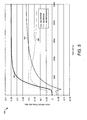
- FIG. 5 is a diagram illustrating an example change in the axial deflections of a rotor, an associated stator and their relative axial deflections according to an illustrative embodiment of the invention.
- FIG. 5 shows a plot 500 representative of example axial deflections of a rotor and an associated stator of a gas turbine during transient and subsequently steady state operation of the gas turbine.
- the horizontal axis may represent time duration (in seconds) of the transient operation such as startup duration, and the subsequent full load operation time of the gas turbine.
- the vertical axis in plot 500 may represent the axial deflection between the stator and rotor parts of the turbine (in inches).
- the plot 500 shows three curves 502, 504 and 506.
- the curve 502 is representative of the axial deflection of the stator with time as the turbine moves from the startup state to the steady state or near steady state.
- the curve 504 is representative of the axial deflection of the rotor during the transient and steady state or near steady state operation of the gas turbine.
- the curve 506 however is representative of the relative axial deflection between the rotor and the stator.
- the curve 506 represents a gradual increase in the relative axial deflection between the rotor and the stator during the startup duration, and then subsequently shows relatively no change in the axial deflection with the onset of the steady state or near steady state operation of the turbine.
- the sealing device may be positioned in the turbine section prior to the start of the turbine such that the inlet hole may initially be uncovered upon startup, and may then be at least partially covered after a time of approximately 5000 seconds from the startup of the turbine.
- FIG. 6 is a flowchart illustrating one example method 600 for controlling radial temperature gradients in a rotor of a gas turbine, according to an illustrative embodiment of the invention.
- the method 600 may begin at block 602.
- an air path is provided to a bore of a rotor, which includes at least one inlet hole and a plurality of holes in the stacked wheels.
- the rotor of a turbine can be formed of a plurality of stacked wheels which include solid wheels placed alternately in between annular wheels.
- the air path can provide an air passage from the hot gas path of the turbine to the bore of the rotor.
- the one or more inlet holes, which form a part of the air path may be in communication with a cavity defined within the rotor. The cavity may be in further communication with the plurality of holes in the solid wheels.
- air from the hot gas path may be directed to the bore of the rotor through a serpentine flow path around the annular wheels and through the solid wheels.
- the serpentine flow path can lead to a relatively larger exposure of the surface area along the length of the turbine wheels to the air flow. This increased exposure of the rotor surface to the purge flow can lead to relatively more effective heating or cooling of the rotor, thus reducing the radial temperature gradient between the rim and the bore of the rotor more effectively during transient operation of the gas turbine.
- the plurality of holes in the solid wheels may be located between about 0.2*R and about 0.65*R from a central axis of each wheel, where R is equal to the rim radius of the solid wheels.
- the flow of purge air through the at least one hole may be controlled based at least in part on axial deflection the rotor and an associated stator during operation of the engine.
- axial deflection the rotor parts there may result an axial deflection of the rotor parts with respect to the stator parts.
- This relative axial deflection between the rotor and the stator parts can increase with time during the startup of the turbine and reaches a maximum at the full load point. Beyond the full load point, the deflection between the rotor and the stator parts may remain almost constant during the entire duration of the steady state operation of the turbine. Further during shutdown, the relative axial deflection between the rotor and the stator parts can again change and decrease with time.
- a sealing device held from an inner circumference of the stator may relatively move with respect to the rotor and cover at least a portion of the inlet hole. Further, as the turbine reaches the steady state or near steady state operation, the sealing device does not move with respect to the rotor, and thus continues to cover at least a part of the inlet hole during the steady state operation of the turbine. Thus, the sealing device may be operable to control the air flow to the inlet hole at all operational states of the gas turbine.
- the axial deflection between the stator and the rotor parts is approximately 0.01 inches to approximately 0.5 inches.
- the sealing device can include one or more bristles mounted to an inner circumference of a sealing hub.
- the outer circumference of this sealing hub may be further mounted to one or more spokes where the one or more spokes may be mounted to the inner circumference of the stator.
- the relative movement between the rotor and the stator can facilitate the motion of the bristles on the rotor surface at least partially covering the inlet hole at the point of maximum axial deflection.
- the spokes are circumferentially arranged such that axial air flow between the stator and rotor may be permitted thus resulting in minimum losses in the flow.
- the method 600 may end following block 604.
- Embodiments of the invention may be applicable to different types of turbines such as steam turbine, gas turbine and the like. Moreover the embodiments of the invention may also be used within different sections of a turbine such as turbine section or compressor section of a gas turbine. It will be apparent that any example taken or provided in the foregoing specification is merely provided for explanation purposes and does not limit the scope of the invention by any means.
Claims (8)
- Verfahren (600) zum Steuern der radialen Temperaturgradienten in einem Rotor einer Gasturbine, wobei das Verfahren umfasst:Bereitstellen (605) eines Weges (220) für die Luft, um zu einer Bohrung (216) des Rotors (202), der mehrere gestapelte Laufräder (206) umfasst, zu strömen, wobei der Weg (220) mindestens ein Eingangsloch (222) auf einer Rotorstruktur und mehrere Löcher (226) in mindestens einigen der gestapelten Laufräder (206, 208) umfasst, undBewegen einer Abdichtungsvorrichtung (224), die von einem Stator (204) gehalten wird und mit dem Rotor (202) verbunden ist, relativ in Bezug auf den Rotor (202), um mindestens einen Abschnitt des mindestens einen Eingangslochs (222) zu bedecken, um auf der Grundlage einer mindestens teilweise axialen Ablenkung zwischen dem Rotor (202) und dem damit verbundenen Stator (204) während des Betriebs der Gasturbine die Luftströmung zu steuern (610), wobei die Abdichtungsvorrichtung (224) ein oder mehrere Borsten (304), die auf einem inneren Umfang einer Abdichtungsnabe (308) befestigt sind, umfasst, wobei ein äußerer Umfang der Abdichtungsnabe (308) an einer oder mehreren Speichen (302), die an einem inneren Umfang des Stators (204) befestigt sind, befestigt ist und wobei Öffnungen (402) zwischen den Speichen (302) einen axialen Luftstrom zwischen dem Stator (204) und dem Rotor (202) ermöglichen, wobei mindestens ein Abschnitt des Luftstroms durch die mehreren Löcher (226) in die gestapelten Laufräder (206, 208) gelenkt wird.
- Verfahren (600) nach Anspruch 1, wobei die gestapelten Laufräder feste (206) und ringförmige (208) Laufräder umfassen, und wobei der Luftstrom durch einen Weg um die ringförmigen Laufräder (208) und durch die festen Laufräder (206) gelenkt wird.
- Verfahren nach Anspruch 2, wobei die mehreren Löcher (226) in den gestapelten Laufrädern (206, 208) zwischen etwa 0,2*R und etwa 0,65*R von einer zentralen Achse eines jeden Laufrads angeordnet sind, wobei R gleich dem Randradius der festen Laufräder (206) ist.
- Verfahren nach einem der vorhergehenden Ansprüche, wobei die axiale Ablenkung zwischen etwa 0,25 mm und etwa 12,7 mm (0,01 und etwa 0,5 inches) liegt.
- System (200) zum Steuern der radialen Temperaturgradienten in einem Rotor (202) einer Gasturbine, wobei die Vorrichtung (200) umfasst:einen Luftstromweg (220) zu einer Bohrung (216) des Rotors (202), der mehrere gestapelte Laufräder (206, 208) umfasst, wobei der Weg mindestens ein Eingangsloch (222) auf einer Rotorstruktur und mehrere Löcher (226) in den gestapelten Laufrädern umfasst; undeine Abdichtungsvorrichtung (224), die von einem Stator (206) gehalten wird und die mit dem Rotor (202) verbunden ist, wobei die Abdichtungsvorrichtung relativ in Bezug auf den Rotor (202) beweglich ist, um mindestens einen Abschnitt des mindestens einen Eingangslochs (222) zu bedecken, um auf der Grundlage einer mindestens teilweise axialen Ablenkung zwischen dem Rotor (202) und dem damit verbundenen Stator (204) während des Betriebs der Gasturbine die Luftströmung zu steuern (610), wobei die Abdichtungsvorrichtung (224) ein oder mehrere Borsten (304), die auf einem inneren Umfang einer Abdichtungsnabe (308) befestigt sind, umfasst, wobei ein äußerer Umfang der Abdichtungsnabe (308) an einer oder mehreren Speichen (302), die an einem inneren Umfang des Stators (204) befestigt sind, befestigt ist und wobei Öffnungen (402) zwischen den Speichen (302) einen axialen Luftstrom zwischen dem Stator (204) und dem Rotor (202) ermöglichen, wobei mindestens ein Abschnitt des Luftstroms durch die mehreren Löcher (226) in die gestapelten Laufräder (206, 208) gelenkt wird.
- System (200) nach Anspruch 5, wobei das mindestens eine Eingangsloch (222) auf der Rotorstruktur in einer Kommunikation mit einem Hohlraum steht, der innerhalb des Rotors (202) definiert ist, wobei der Hohlraum in einer Kommunikation mit mehreren Löchern (226) in den gestapelten Laufrädern (206, 208) steht.
- System nach Anspruch 5 oder 6, wobei die axiale Dichtungsringweite zwischen annähernd 1,52 mm und 12,7 mm (0,06 und 0,5 inches) liegt.
- System (200) nach einem der Ansprüche 5 bis 7, wobei die gestapelten Laufräder feste (206) und ringförmige (208) Laufräder umfassen, und wobei der Luftstrom durch einen Weg (220) um die ringförmigen Laufräder (208) und durch die festen Laufräder (210) gelenkt wird.
Applications Claiming Priority (1)
| Application Number | Priority Date | Filing Date | Title |
|---|---|---|---|
| US12/409,641 US8186933B2 (en) | 2009-03-24 | 2009-03-24 | Systems, methods, and apparatus for passive purge flow control in a turbine |
Publications (3)
| Publication Number | Publication Date |
|---|---|
| EP2236747A2 EP2236747A2 (de) | 2010-10-06 |
| EP2236747A3 EP2236747A3 (de) | 2013-02-27 |
| EP2236747B1 true EP2236747B1 (de) | 2014-05-07 |
Family
ID=42229121
Family Applications (1)
| Application Number | Title | Priority Date | Filing Date |
|---|---|---|---|
| EP10156534.9A Not-in-force EP2236747B1 (de) | 2009-03-24 | 2010-03-15 | Systeme, Verfahren und Vorrichtung zur passiven Reinigungsströmungssteuerung in Turbinen |
Country Status (4)
| Country | Link |
|---|---|
| US (1) | US8186933B2 (de) |
| EP (1) | EP2236747B1 (de) |
| JP (1) | JP5550400B2 (de) |
| CN (1) | CN101852097B (de) |
Families Citing this family (17)
| Publication number | Priority date | Publication date | Assignee | Title |
|---|---|---|---|---|
| US20120134782A1 (en) * | 2010-11-30 | 2012-05-31 | Creston Lewis Dempsey | Purge systems for rotary machines and methods of assembling same |
| KR101271875B1 (ko) | 2010-12-25 | 2013-06-05 | 주식회사 포스코 | 에어 퍼지 장치 및 이를 포함하는 결함 검출기 |
| US8807941B2 (en) * | 2011-02-03 | 2014-08-19 | General Electric Company | Cross-over purge flow system for a turbomachine wheel member |
| WO2014197044A2 (en) | 2013-03-12 | 2014-12-11 | United Technologies Corporation | Vane tip machining fixture assembly |
| US9528377B2 (en) | 2013-08-21 | 2016-12-27 | General Electric Company | Method and system for cooling rotor blade angelwings |
| EP3044440B1 (de) * | 2013-09-10 | 2019-12-11 | United Technologies Corporation | Fluidinjektor zur kühlung eines gasturbinenmotorbauteils |
| US9664118B2 (en) | 2013-10-24 | 2017-05-30 | General Electric Company | Method and system for controlling compressor forward leakage |
| EP2868865A1 (de) * | 2013-10-31 | 2015-05-06 | Siemens Aktiengesellschaft | Gasturbine sowie Verfahren zu deren Kühlung |
| EP2868866A1 (de) * | 2013-10-31 | 2015-05-06 | Siemens Aktiengesellschaft | Verdichter für eine Gasturbine mit einem inneren Temperaturausgleich |
| US10036263B2 (en) | 2014-10-22 | 2018-07-31 | United Technologies Corporation | Stator assembly with pad interface for a gas turbine engine |
| US10612383B2 (en) * | 2016-01-27 | 2020-04-07 | General Electric Company | Compressor aft rotor rim cooling for high OPR (T3) engine |
| US10947993B2 (en) | 2017-11-27 | 2021-03-16 | General Electric Company | Thermal gradient attenuation structure to mitigate rotor bow in turbine engine |
| CN109113795A (zh) * | 2018-10-23 | 2019-01-01 | 中国船舶重工集团公司第七0三研究所 | 一种氦气轮机转子叶盘 |
| US11035251B2 (en) | 2019-09-26 | 2021-06-15 | General Electric Company | Stator temperature control system for a gas turbine engine |
| US11525400B2 (en) | 2020-07-08 | 2022-12-13 | General Electric Company | System for rotor assembly thermal gradient reduction |
| US11821326B2 (en) * | 2021-04-27 | 2023-11-21 | General Electric Company | Turbine containment system |
| US11879411B2 (en) | 2022-04-07 | 2024-01-23 | General Electric Company | System and method for mitigating bowed rotor in a gas turbine engine |
Family Cites Families (24)
| Publication number | Priority date | Publication date | Assignee | Title |
|---|---|---|---|---|
| US4023919A (en) * | 1974-12-19 | 1977-05-17 | General Electric Company | Thermal actuated valve for clearance control |
| US4445815A (en) * | 1980-06-09 | 1984-05-01 | United Technologies Corporation | Temperature regulation of air cycle refrigeration systems |
| US5316437A (en) * | 1993-02-19 | 1994-05-31 | General Electric Company | Gas turbine engine structural frame assembly having a thermally actuated valve for modulating a flow of hot gases through the frame hub |
| GB9401735D0 (en) * | 1994-01-29 | 1994-03-23 | Rolls Royce Plc | Component support structure |
| US5839267A (en) * | 1995-03-31 | 1998-11-24 | General Electric Co. | Cycle for steam cooled gas turbines |
| US5593274A (en) * | 1995-03-31 | 1997-01-14 | General Electric Co. | Closed or open circuit cooling of turbine rotor components |
| KR100389990B1 (ko) * | 1995-04-06 | 2003-11-17 | 가부시끼가이샤 히다치 세이사꾸쇼 | 가스터빈 |
| US5782076A (en) * | 1996-05-17 | 1998-07-21 | Westinghouse Electric Corporation | Closed loop air cooling system for combustion turbines |
| JP3901828B2 (ja) * | 1998-02-17 | 2007-04-04 | 三菱重工業株式会社 | 蒸気冷却ガスタービン |
| US6077035A (en) * | 1998-03-27 | 2000-06-20 | Pratt & Whitney Canada Corp. | Deflector for controlling entry of cooling air leakage into the gaspath of a gas turbine engine |
| KR20000071653A (ko) * | 1999-04-15 | 2000-11-25 | 제이 엘. 차스킨, 버나드 스나이더, 아더엠. 킹 | 육상용 가스 터빈 및 가스 터빈의 하나의 단을 냉각시키는방법 |
| DE19951570A1 (de) * | 1999-10-27 | 2001-05-03 | Abb Patent Gmbh | Einrichtung zur Kompensierung des Axialschubs bei Turbomaschinen |
| JP3361501B2 (ja) * | 2000-03-02 | 2003-01-07 | 株式会社日立製作所 | 閉回路翼冷却タービン |
| DE10160996A1 (de) * | 2001-12-12 | 2003-06-18 | Rolls Royce Deutschland | Vorrichtung zur Luftmassenstromregelung |
| DE10303340A1 (de) * | 2003-01-29 | 2004-08-26 | Alstom Technology Ltd | Kühleinrichtung |
| US6942445B2 (en) * | 2003-12-04 | 2005-09-13 | Honeywell International Inc. | Gas turbine cooled shroud assembly with hot gas ingestion suppression |
| GB0403198D0 (en) * | 2004-02-13 | 2004-03-17 | Rolls Royce Plc | Casing arrangement |
| DE102004014118A1 (de) | 2004-03-23 | 2005-10-13 | Alstom Technology Ltd | Anordnung zur Abdichtung eines Übergangs zwischen Kühlpassagen zweier Komponenten einer Turbomaschine |
| US7090459B2 (en) * | 2004-03-31 | 2006-08-15 | General Electric Company | Hybrid seal and system and method incorporating the same |
| PL1907670T3 (pl) * | 2005-07-27 | 2009-04-30 | Siemens Ag | Chłodzona łopatka dla turbiny gazowej i zastosowanie takiej łopatki turbiny |
| US8057157B2 (en) * | 2007-10-22 | 2011-11-15 | General Electric Company | System for delivering air from a multi-stage compressor to a turbine portion of a gas turbine engine |
| US8016297B2 (en) * | 2008-03-27 | 2011-09-13 | United Technologies Corporation | Gas turbine engine seals and engines incorporating such seals |
| US8038399B1 (en) * | 2008-11-22 | 2011-10-18 | Florida Turbine Technologies, Inc. | Turbine rim cavity sealing |
| US7993102B2 (en) * | 2009-01-09 | 2011-08-09 | General Electric Company | Rotor cooling circuit |
-
2009
- 2009-03-24 US US12/409,641 patent/US8186933B2/en not_active Expired - Fee Related
-
2010
- 2010-03-15 EP EP10156534.9A patent/EP2236747B1/de not_active Not-in-force
- 2010-03-19 JP JP2010063517A patent/JP5550400B2/ja not_active Expired - Fee Related
- 2010-03-23 CN CN201010155651XA patent/CN101852097B/zh not_active Expired - Fee Related
Also Published As
| Publication number | Publication date |
|---|---|
| EP2236747A2 (de) | 2010-10-06 |
| EP2236747A3 (de) | 2013-02-27 |
| US20100247282A1 (en) | 2010-09-30 |
| JP5550400B2 (ja) | 2014-07-16 |
| CN101852097B (zh) | 2013-08-21 |
| US8186933B2 (en) | 2012-05-29 |
| CN101852097A (zh) | 2010-10-06 |
| JP2010223228A (ja) | 2010-10-07 |
Similar Documents
| Publication | Publication Date | Title |
|---|---|---|
| EP2236747B1 (de) | Systeme, Verfahren und Vorrichtung zur passiven Reinigungsströmungssteuerung in Turbinen | |
| RU2599413C2 (ru) | Канал для охлаждения корпуса | |
| JP6126438B2 (ja) | ガスタービンのクリアランス制御システム | |
| JP4975990B2 (ja) | ロータ組立体の先端間隙を維持するための方法及び装置 | |
| EP2546471B1 (de) | Spitzenabstandssteuerung für Turbinenschaufeln | |
| EP2587028B1 (de) | Aktives spaltregelungs-system und verfahren für ein gasturbinentriebwerk | |
| CN101845996B (zh) | 用于在燃气轮机中减少二次空气流的装置和系统 | |
| EP3023600B1 (de) | Motorgehäuseelement | |
| US8529194B2 (en) | Shank cavity and cooling hole | |
| JP6739934B2 (ja) | ガスタービンのシール | |
| KR101720476B1 (ko) | 가스 터빈 | |
| US10329940B2 (en) | Method and system for passive clearance control in a gas turbine engine | |
| JP2013083250A (ja) | ガスタービン | |
| JP5543029B2 (ja) | ターボ機械のための内部冷却装置 | |
| WO2015056656A1 (ja) | ガスタービン | |
| JP2013151936A (ja) | 後付け可能な、段間の傾斜シール | |
| US10487689B2 (en) | Turbine casing comprising ring sector attachment means | |
| CA2875408A1 (en) | Seal system for a gas turbine | |
| JP2011085136A (ja) | ターボ機械ロータ冷却 | |
| US20140271154A1 (en) | Casing for turbine engine having a cooling unit | |
| KR102272728B1 (ko) | 증기 터빈 및 증기 터빈 조립 방법 | |
| EP2378088A2 (de) | Turbine mit einem doppelten Gehäuse | |
| CN110431286B (zh) | 用于涡轮机的尖端平衡狭缝 | |
| JP5478576B2 (ja) | ガスタービン | |
| US11512594B2 (en) | System and method for modulating airflow into a bore of a rotor to control blade tip clearance |
Legal Events
| Date | Code | Title | Description |
|---|---|---|---|
| PUAI | Public reference made under article 153(3) epc to a published international application that has entered the european phase |
Free format text: ORIGINAL CODE: 0009012 |
|
| AK | Designated contracting states |
Kind code of ref document: A2 Designated state(s): AT BE BG CH CY CZ DE DK EE ES FI FR GB GR HR HU IE IS IT LI LT LU LV MC MK MT NL NO PL PT RO SE SI SK SM TR |
|
| AX | Request for extension of the european patent |
Extension state: AL BA ME RS |
|
| PUAL | Search report despatched |
Free format text: ORIGINAL CODE: 0009013 |
|
| AK | Designated contracting states |
Kind code of ref document: A3 Designated state(s): AT BE BG CH CY CZ DE DK EE ES FI FR GB GR HR HU IE IS IT LI LT LU LV MC MK MT NL NO PL PT RO SE SI SK SM TR |
|
| AX | Request for extension of the european patent |
Extension state: AL BA ME RS |
|
| RIC1 | Information provided on ipc code assigned before grant |
Ipc: F01D 11/00 20060101ALI20130122BHEP Ipc: F01D 5/06 20060101ALI20130122BHEP Ipc: F02C 7/18 20060101ALI20130122BHEP Ipc: F01D 5/08 20060101AFI20130122BHEP |
|
| 17P | Request for examination filed |
Effective date: 20130827 |
|
| RBV | Designated contracting states (corrected) |
Designated state(s): AT BE BG CH CY CZ DE DK EE ES FI FR GB GR HR HU IE IS IT LI LT LU LV MC MK MT NL NO PL PT RO SE SI SK SM TR |
|
| GRAP | Despatch of communication of intention to grant a patent |
Free format text: ORIGINAL CODE: EPIDOSNIGR1 |
|
| RIC1 | Information provided on ipc code assigned before grant |
Ipc: F01D 11/00 20060101ALI20130927BHEP Ipc: F02C 7/18 20060101ALI20130927BHEP Ipc: F01D 5/08 20060101AFI20130927BHEP Ipc: F01D 5/06 20060101ALI20130927BHEP |
|
| INTG | Intention to grant announced |
Effective date: 20131029 |
|
| RIN1 | Information on inventor provided before grant (corrected) |
Inventor name: DEODHAR, SUBODH D. Inventor name: DOSS, JEYAMANI M. Inventor name: MEKA, HARI K. |
|
| GRAS | Grant fee paid |
Free format text: ORIGINAL CODE: EPIDOSNIGR3 |
|
| GRAA | (expected) grant |
Free format text: ORIGINAL CODE: 0009210 |
|
| AK | Designated contracting states |
Kind code of ref document: B1 Designated state(s): AT BE BG CH CY CZ DE DK EE ES FI FR GB GR HR HU IE IS IT LI LT LU LV MC MK MT NL NO PL PT RO SE SI SK SM TR |
|
| REG | Reference to a national code |
Ref country code: GB Ref legal event code: FG4D |
|
| REG | Reference to a national code |
Ref country code: AT Ref legal event code: REF Ref document number: 666877 Country of ref document: AT Kind code of ref document: T Effective date: 20140515 |
|
| REG | Reference to a national code |
Ref country code: IE Ref legal event code: FG4D |
|
| REG | Reference to a national code |
Ref country code: DE Ref legal event code: R096 Ref document number: 602010015762 Country of ref document: DE Effective date: 20140618 |
|
| REG | Reference to a national code |
Ref country code: AT Ref legal event code: MK05 Ref document number: 666877 Country of ref document: AT Kind code of ref document: T Effective date: 20140507 |
|
| REG | Reference to a national code |
Ref country code: NL Ref legal event code: VDEP Effective date: 20140507 |
|
| REG | Reference to a national code |
Ref country code: LT Ref legal event code: MG4D |
|
| PG25 | Lapsed in a contracting state [announced via postgrant information from national office to epo] |
Ref country code: IS Free format text: LAPSE BECAUSE OF FAILURE TO SUBMIT A TRANSLATION OF THE DESCRIPTION OR TO PAY THE FEE WITHIN THE PRESCRIBED TIME-LIMIT Effective date: 20140907 Ref country code: GR Free format text: LAPSE BECAUSE OF FAILURE TO SUBMIT A TRANSLATION OF THE DESCRIPTION OR TO PAY THE FEE WITHIN THE PRESCRIBED TIME-LIMIT Effective date: 20140808 Ref country code: CY Free format text: LAPSE BECAUSE OF FAILURE TO SUBMIT A TRANSLATION OF THE DESCRIPTION OR TO PAY THE FEE WITHIN THE PRESCRIBED TIME-LIMIT Effective date: 20140507 Ref country code: FI Free format text: LAPSE BECAUSE OF FAILURE TO SUBMIT A TRANSLATION OF THE DESCRIPTION OR TO PAY THE FEE WITHIN THE PRESCRIBED TIME-LIMIT Effective date: 20140507 Ref country code: NO Free format text: LAPSE BECAUSE OF FAILURE TO SUBMIT A TRANSLATION OF THE DESCRIPTION OR TO PAY THE FEE WITHIN THE PRESCRIBED TIME-LIMIT Effective date: 20140807 Ref country code: LT Free format text: LAPSE BECAUSE OF FAILURE TO SUBMIT A TRANSLATION OF THE DESCRIPTION OR TO PAY THE FEE WITHIN THE PRESCRIBED TIME-LIMIT Effective date: 20140507 |
|
| PG25 | Lapsed in a contracting state [announced via postgrant information from national office to epo] |
Ref country code: AT Free format text: LAPSE BECAUSE OF FAILURE TO SUBMIT A TRANSLATION OF THE DESCRIPTION OR TO PAY THE FEE WITHIN THE PRESCRIBED TIME-LIMIT Effective date: 20140507 Ref country code: ES Free format text: LAPSE BECAUSE OF FAILURE TO SUBMIT A TRANSLATION OF THE DESCRIPTION OR TO PAY THE FEE WITHIN THE PRESCRIBED TIME-LIMIT Effective date: 20140507 Ref country code: HR Free format text: LAPSE BECAUSE OF FAILURE TO SUBMIT A TRANSLATION OF THE DESCRIPTION OR TO PAY THE FEE WITHIN THE PRESCRIBED TIME-LIMIT Effective date: 20140507 Ref country code: PL Free format text: LAPSE BECAUSE OF FAILURE TO SUBMIT A TRANSLATION OF THE DESCRIPTION OR TO PAY THE FEE WITHIN THE PRESCRIBED TIME-LIMIT Effective date: 20140507 Ref country code: LV Free format text: LAPSE BECAUSE OF FAILURE TO SUBMIT A TRANSLATION OF THE DESCRIPTION OR TO PAY THE FEE WITHIN THE PRESCRIBED TIME-LIMIT Effective date: 20140507 Ref country code: SE Free format text: LAPSE BECAUSE OF FAILURE TO SUBMIT A TRANSLATION OF THE DESCRIPTION OR TO PAY THE FEE WITHIN THE PRESCRIBED TIME-LIMIT Effective date: 20140507 |
|
| PG25 | Lapsed in a contracting state [announced via postgrant information from national office to epo] |
Ref country code: PT Free format text: LAPSE BECAUSE OF FAILURE TO SUBMIT A TRANSLATION OF THE DESCRIPTION OR TO PAY THE FEE WITHIN THE PRESCRIBED TIME-LIMIT Effective date: 20140908 |
|
| PG25 | Lapsed in a contracting state [announced via postgrant information from national office to epo] |
Ref country code: EE Free format text: LAPSE BECAUSE OF FAILURE TO SUBMIT A TRANSLATION OF THE DESCRIPTION OR TO PAY THE FEE WITHIN THE PRESCRIBED TIME-LIMIT Effective date: 20140507 Ref country code: BE Free format text: LAPSE BECAUSE OF FAILURE TO SUBMIT A TRANSLATION OF THE DESCRIPTION OR TO PAY THE FEE WITHIN THE PRESCRIBED TIME-LIMIT Effective date: 20140507 Ref country code: CZ Free format text: LAPSE BECAUSE OF FAILURE TO SUBMIT A TRANSLATION OF THE DESCRIPTION OR TO PAY THE FEE WITHIN THE PRESCRIBED TIME-LIMIT Effective date: 20140507 Ref country code: RO Free format text: LAPSE BECAUSE OF FAILURE TO SUBMIT A TRANSLATION OF THE DESCRIPTION OR TO PAY THE FEE WITHIN THE PRESCRIBED TIME-LIMIT Effective date: 20140507 Ref country code: DK Free format text: LAPSE BECAUSE OF FAILURE TO SUBMIT A TRANSLATION OF THE DESCRIPTION OR TO PAY THE FEE WITHIN THE PRESCRIBED TIME-LIMIT Effective date: 20140507 Ref country code: SK Free format text: LAPSE BECAUSE OF FAILURE TO SUBMIT A TRANSLATION OF THE DESCRIPTION OR TO PAY THE FEE WITHIN THE PRESCRIBED TIME-LIMIT Effective date: 20140507 |
|
| REG | Reference to a national code |
Ref country code: DE Ref legal event code: R097 Ref document number: 602010015762 Country of ref document: DE |
|
| PG25 | Lapsed in a contracting state [announced via postgrant information from national office to epo] |
Ref country code: NL Free format text: LAPSE BECAUSE OF FAILURE TO SUBMIT A TRANSLATION OF THE DESCRIPTION OR TO PAY THE FEE WITHIN THE PRESCRIBED TIME-LIMIT Effective date: 20140507 |
|
| PLBE | No opposition filed within time limit |
Free format text: ORIGINAL CODE: 0009261 |
|
| STAA | Information on the status of an ep patent application or granted ep patent |
Free format text: STATUS: NO OPPOSITION FILED WITHIN TIME LIMIT |
|
| 26N | No opposition filed |
Effective date: 20150210 |
|
| PG25 | Lapsed in a contracting state [announced via postgrant information from national office to epo] |
Ref country code: IT Free format text: LAPSE BECAUSE OF FAILURE TO SUBMIT A TRANSLATION OF THE DESCRIPTION OR TO PAY THE FEE WITHIN THE PRESCRIBED TIME-LIMIT Effective date: 20140507 |
|
| REG | Reference to a national code |
Ref country code: DE Ref legal event code: R097 Ref document number: 602010015762 Country of ref document: DE Effective date: 20150210 |
|
| PG25 | Lapsed in a contracting state [announced via postgrant information from national office to epo] |
Ref country code: SI Free format text: LAPSE BECAUSE OF FAILURE TO SUBMIT A TRANSLATION OF THE DESCRIPTION OR TO PAY THE FEE WITHIN THE PRESCRIBED TIME-LIMIT Effective date: 20140507 |
|
| PG25 | Lapsed in a contracting state [announced via postgrant information from national office to epo] |
Ref country code: LU Free format text: LAPSE BECAUSE OF FAILURE TO SUBMIT A TRANSLATION OF THE DESCRIPTION OR TO PAY THE FEE WITHIN THE PRESCRIBED TIME-LIMIT Effective date: 20150315 Ref country code: MC Free format text: LAPSE BECAUSE OF FAILURE TO SUBMIT A TRANSLATION OF THE DESCRIPTION OR TO PAY THE FEE WITHIN THE PRESCRIBED TIME-LIMIT Effective date: 20140507 |
|
| REG | Reference to a national code |
Ref country code: FR Ref legal event code: ST Effective date: 20151130 |
|
| REG | Reference to a national code |
Ref country code: IE Ref legal event code: MM4A |
|
| PG25 | Lapsed in a contracting state [announced via postgrant information from national office to epo] |
Ref country code: IE Free format text: LAPSE BECAUSE OF NON-PAYMENT OF DUE FEES Effective date: 20150315 |
|
| PG25 | Lapsed in a contracting state [announced via postgrant information from national office to epo] |
Ref country code: FR Free format text: LAPSE BECAUSE OF NON-PAYMENT OF DUE FEES Effective date: 20150331 |
|
| PG25 | Lapsed in a contracting state [announced via postgrant information from national office to epo] |
Ref country code: MT Free format text: LAPSE BECAUSE OF FAILURE TO SUBMIT A TRANSLATION OF THE DESCRIPTION OR TO PAY THE FEE WITHIN THE PRESCRIBED TIME-LIMIT Effective date: 20140507 |
|
| PGFP | Annual fee paid to national office [announced via postgrant information from national office to epo] |
Ref country code: CH Payment date: 20170327 Year of fee payment: 8 |
|
| PG25 | Lapsed in a contracting state [announced via postgrant information from national office to epo] |
Ref country code: BG Free format text: LAPSE BECAUSE OF FAILURE TO SUBMIT A TRANSLATION OF THE DESCRIPTION OR TO PAY THE FEE WITHIN THE PRESCRIBED TIME-LIMIT Effective date: 20140507 Ref country code: HU Free format text: LAPSE BECAUSE OF FAILURE TO SUBMIT A TRANSLATION OF THE DESCRIPTION OR TO PAY THE FEE WITHIN THE PRESCRIBED TIME-LIMIT; INVALID AB INITIO Effective date: 20100315 Ref country code: SM Free format text: LAPSE BECAUSE OF FAILURE TO SUBMIT A TRANSLATION OF THE DESCRIPTION OR TO PAY THE FEE WITHIN THE PRESCRIBED TIME-LIMIT Effective date: 20140507 |
|
| PGFP | Annual fee paid to national office [announced via postgrant information from national office to epo] |
Ref country code: GB Payment date: 20170327 Year of fee payment: 8 |
|
| PGFP | Annual fee paid to national office [announced via postgrant information from national office to epo] |
Ref country code: DE Payment date: 20170329 Year of fee payment: 8 |
|
| PG25 | Lapsed in a contracting state [announced via postgrant information from national office to epo] |
Ref country code: TR Free format text: LAPSE BECAUSE OF FAILURE TO SUBMIT A TRANSLATION OF THE DESCRIPTION OR TO PAY THE FEE WITHIN THE PRESCRIBED TIME-LIMIT Effective date: 20140507 |
|
| PG25 | Lapsed in a contracting state [announced via postgrant information from national office to epo] |
Ref country code: MK Free format text: LAPSE BECAUSE OF FAILURE TO SUBMIT A TRANSLATION OF THE DESCRIPTION OR TO PAY THE FEE WITHIN THE PRESCRIBED TIME-LIMIT Effective date: 20140507 |
|
| REG | Reference to a national code |
Ref country code: DE Ref legal event code: R119 Ref document number: 602010015762 Country of ref document: DE |
|
| REG | Reference to a national code |
Ref country code: CH Ref legal event code: PL |
|
| GBPC | Gb: european patent ceased through non-payment of renewal fee |
Effective date: 20180315 |
|
| PG25 | Lapsed in a contracting state [announced via postgrant information from national office to epo] |
Ref country code: DE Free format text: LAPSE BECAUSE OF NON-PAYMENT OF DUE FEES Effective date: 20181002 |
|
| PG25 | Lapsed in a contracting state [announced via postgrant information from national office to epo] |
Ref country code: LI Free format text: LAPSE BECAUSE OF NON-PAYMENT OF DUE FEES Effective date: 20180331 Ref country code: CH Free format text: LAPSE BECAUSE OF NON-PAYMENT OF DUE FEES Effective date: 20180331 Ref country code: GB Free format text: LAPSE BECAUSE OF NON-PAYMENT OF DUE FEES Effective date: 20180315 |