WO2015056656A1 - ガスタービン - Google Patents
ガスタービン Download PDFInfo
- Publication number
- WO2015056656A1 WO2015056656A1 PCT/JP2014/077262 JP2014077262W WO2015056656A1 WO 2015056656 A1 WO2015056656 A1 WO 2015056656A1 JP 2014077262 W JP2014077262 W JP 2014077262W WO 2015056656 A1 WO2015056656 A1 WO 2015056656A1
- Authority
- WO
- WIPO (PCT)
- Prior art keywords
- air
- gas turbine
- blade
- ring
- compressor
- Prior art date
Links
Images


Classifications
-
- F—MECHANICAL ENGINEERING; LIGHTING; HEATING; WEAPONS; BLASTING
- F01—MACHINES OR ENGINES IN GENERAL; ENGINE PLANTS IN GENERAL; STEAM ENGINES
- F01D—NON-POSITIVE DISPLACEMENT MACHINES OR ENGINES, e.g. STEAM TURBINES
- F01D5/00—Blades; Blade-carrying members; Heating, heat-insulating, cooling or antivibration means on the blades or the members
- F01D5/02—Blade-carrying members, e.g. rotors
- F01D5/08—Heating, heat-insulating or cooling means
- F01D5/081—Cooling fluid being directed on the side of the rotor disc or at the roots of the blades
-
- F—MECHANICAL ENGINEERING; LIGHTING; HEATING; WEAPONS; BLASTING
- F01—MACHINES OR ENGINES IN GENERAL; ENGINE PLANTS IN GENERAL; STEAM ENGINES
- F01D—NON-POSITIVE DISPLACEMENT MACHINES OR ENGINES, e.g. STEAM TURBINES
- F01D25/00—Component parts, details, or accessories, not provided for in, or of interest apart from, other groups
- F01D25/08—Cooling; Heating; Heat-insulation
- F01D25/14—Casings modified therefor
-
- F—MECHANICAL ENGINEERING; LIGHTING; HEATING; WEAPONS; BLASTING
- F02—COMBUSTION ENGINES; HOT-GAS OR COMBUSTION-PRODUCT ENGINE PLANTS
- F02C—GAS-TURBINE PLANTS; AIR INTAKES FOR JET-PROPULSION PLANTS; CONTROLLING FUEL SUPPLY IN AIR-BREATHING JET-PROPULSION PLANTS
- F02C3/00—Gas-turbine plants characterised by the use of combustion products as the working fluid
- F02C3/04—Gas-turbine plants characterised by the use of combustion products as the working fluid having a turbine driving a compressor
-
- F—MECHANICAL ENGINEERING; LIGHTING; HEATING; WEAPONS; BLASTING
- F02—COMBUSTION ENGINES; HOT-GAS OR COMBUSTION-PRODUCT ENGINE PLANTS
- F02C—GAS-TURBINE PLANTS; AIR INTAKES FOR JET-PROPULSION PLANTS; CONTROLLING FUEL SUPPLY IN AIR-BREATHING JET-PROPULSION PLANTS
- F02C7/00—Features, components parts, details or accessories, not provided for in, or of interest apart form groups F02C1/00 - F02C6/00; Air intakes for jet-propulsion plants
- F02C7/12—Cooling of plants
- F02C7/16—Cooling of plants characterised by cooling medium
- F02C7/18—Cooling of plants characterised by cooling medium the medium being gaseous, e.g. air
-
- F—MECHANICAL ENGINEERING; LIGHTING; HEATING; WEAPONS; BLASTING
- F02—COMBUSTION ENGINES; HOT-GAS OR COMBUSTION-PRODUCT ENGINE PLANTS
- F02C—GAS-TURBINE PLANTS; AIR INTAKES FOR JET-PROPULSION PLANTS; CONTROLLING FUEL SUPPLY IN AIR-BREATHING JET-PROPULSION PLANTS
- F02C9/00—Controlling gas-turbine plants; Controlling fuel supply in air- breathing jet-propulsion plants
- F02C9/16—Control of working fluid flow
- F02C9/18—Control of working fluid flow by bleeding, bypassing or acting on variable working fluid interconnections between turbines or compressors or their stages
-
- F—MECHANICAL ENGINEERING; LIGHTING; HEATING; WEAPONS; BLASTING
- F04—POSITIVE - DISPLACEMENT MACHINES FOR LIQUIDS; PUMPS FOR LIQUIDS OR ELASTIC FLUIDS
- F04D—NON-POSITIVE-DISPLACEMENT PUMPS
- F04D29/00—Details, component parts, or accessories
- F04D29/26—Rotors specially for elastic fluids
- F04D29/32—Rotors specially for elastic fluids for axial flow pumps
- F04D29/321—Rotors specially for elastic fluids for axial flow pumps for axial flow compressors
- F04D29/324—Blades
-
- F—MECHANICAL ENGINEERING; LIGHTING; HEATING; WEAPONS; BLASTING
- F04—POSITIVE - DISPLACEMENT MACHINES FOR LIQUIDS; PUMPS FOR LIQUIDS OR ELASTIC FLUIDS
- F04D—NON-POSITIVE-DISPLACEMENT PUMPS
- F04D29/00—Details, component parts, or accessories
- F04D29/40—Casings; Connections of working fluid
- F04D29/52—Casings; Connections of working fluid for axial pumps
- F04D29/522—Casings; Connections of working fluid for axial pumps especially adapted for elastic fluid pumps
-
- F—MECHANICAL ENGINEERING; LIGHTING; HEATING; WEAPONS; BLASTING
- F04—POSITIVE - DISPLACEMENT MACHINES FOR LIQUIDS; PUMPS FOR LIQUIDS OR ELASTIC FLUIDS
- F04D—NON-POSITIVE-DISPLACEMENT PUMPS
- F04D29/00—Details, component parts, or accessories
- F04D29/40—Casings; Connections of working fluid
- F04D29/52—Casings; Connections of working fluid for axial pumps
- F04D29/54—Fluid-guiding means, e.g. diffusers
- F04D29/541—Specially adapted for elastic fluid pumps
- F04D29/542—Bladed diffusers
-
- F—MECHANICAL ENGINEERING; LIGHTING; HEATING; WEAPONS; BLASTING
- F04—POSITIVE - DISPLACEMENT MACHINES FOR LIQUIDS; PUMPS FOR LIQUIDS OR ELASTIC FLUIDS
- F04D—NON-POSITIVE-DISPLACEMENT PUMPS
- F04D29/00—Details, component parts, or accessories
- F04D29/58—Cooling; Heating; Diminishing heat transfer
- F04D29/582—Cooling; Heating; Diminishing heat transfer specially adapted for elastic fluid pumps
- F04D29/584—Cooling; Heating; Diminishing heat transfer specially adapted for elastic fluid pumps cooling or heating the machine
-
- F—MECHANICAL ENGINEERING; LIGHTING; HEATING; WEAPONS; BLASTING
- F04—POSITIVE - DISPLACEMENT MACHINES FOR LIQUIDS; PUMPS FOR LIQUIDS OR ELASTIC FLUIDS
- F04D—NON-POSITIVE-DISPLACEMENT PUMPS
- F04D29/00—Details, component parts, or accessories
- F04D29/58—Cooling; Heating; Diminishing heat transfer
- F04D29/582—Cooling; Heating; Diminishing heat transfer specially adapted for elastic fluid pumps
- F04D29/5853—Cooling; Heating; Diminishing heat transfer specially adapted for elastic fluid pumps heat insulation or conduction
-
- F—MECHANICAL ENGINEERING; LIGHTING; HEATING; WEAPONS; BLASTING
- F05—INDEXING SCHEMES RELATING TO ENGINES OR PUMPS IN VARIOUS SUBCLASSES OF CLASSES F01-F04
- F05D—INDEXING SCHEME FOR ASPECTS RELATING TO NON-POSITIVE-DISPLACEMENT MACHINES OR ENGINES, GAS-TURBINES OR JET-PROPULSION PLANTS
- F05D2220/00—Application
- F05D2220/30—Application in turbines
- F05D2220/32—Application in turbines in gas turbines
- F05D2220/321—Application in turbines in gas turbines for a special turbine stage
- F05D2220/3216—Application in turbines in gas turbines for a special turbine stage for a special compressor stage
- F05D2220/3219—Application in turbines in gas turbines for a special turbine stage for a special compressor stage for the last stage of a compressor or a high pressure compressor
-
- F—MECHANICAL ENGINEERING; LIGHTING; HEATING; WEAPONS; BLASTING
- F05—INDEXING SCHEMES RELATING TO ENGINES OR PUMPS IN VARIOUS SUBCLASSES OF CLASSES F01-F04
- F05D—INDEXING SCHEME FOR ASPECTS RELATING TO NON-POSITIVE-DISPLACEMENT MACHINES OR ENGINES, GAS-TURBINES OR JET-PROPULSION PLANTS
- F05D2240/00—Components
- F05D2240/35—Combustors or associated equipment
-
- F—MECHANICAL ENGINEERING; LIGHTING; HEATING; WEAPONS; BLASTING
- F05—INDEXING SCHEMES RELATING TO ENGINES OR PUMPS IN VARIOUS SUBCLASSES OF CLASSES F01-F04
- F05D—INDEXING SCHEME FOR ASPECTS RELATING TO NON-POSITIVE-DISPLACEMENT MACHINES OR ENGINES, GAS-TURBINES OR JET-PROPULSION PLANTS
- F05D2260/00—Function
- F05D2260/20—Heat transfer, e.g. cooling
- F05D2260/205—Cooling fluid recirculation, i.e. after cooling one or more components is the cooling fluid recovered and used elsewhere for other purposes
-
- F—MECHANICAL ENGINEERING; LIGHTING; HEATING; WEAPONS; BLASTING
- F05—INDEXING SCHEMES RELATING TO ENGINES OR PUMPS IN VARIOUS SUBCLASSES OF CLASSES F01-F04
- F05D—INDEXING SCHEME FOR ASPECTS RELATING TO NON-POSITIVE-DISPLACEMENT MACHINES OR ENGINES, GAS-TURBINES OR JET-PROPULSION PLANTS
- F05D2260/00—Function
- F05D2260/20—Heat transfer, e.g. cooling
- F05D2260/213—Heat transfer, e.g. cooling by the provision of a heat exchanger within the cooling circuit
Definitions
- the present invention relates to, for example, a gas turbine that supplies fuel to and combusts compressed high-temperature high-pressure air and supplies generated combustion gas to the turbine to obtain rotational power.
- a typical gas turbine is composed of a compressor, a combustor and a turbine.
- the compressor compresses the air taken in from the air intake into high temperature / high pressure compressed air.
- the combustor supplies a fuel to the compressed air and burns it to obtain a high temperature and high pressure combustion gas.
- the turbine is driven by the combustion gas to drive a coaxially coupled generator.
- the compressor in this gas turbine is configured by alternately arranging a plurality of stator blades and blades in the vehicle compartment along the air flow direction, and the air taken in from the air intake port is a plurality of static It becomes compressed air of high temperature and high pressure by being compressed passing through the wings and blades.
- a gas turbine there is, for example, one described in Patent Document 1 below.
- each moving blade rotates at high speed, and the tip extends radially outward, while the air passage (blade ring) on the vehicle compartment side Shrinks inward by being cooled by the low temperature air taken in.
- the gap between the tip of the moving blade and the inner wall surface of the blade ring forming the air passage is temporarily reduced.
- each moving blade and blade ring are stretched by being heated by the high temperature and high pressure compressed air.
- the gap between the tip of the blade and the inner wall surface of the blade ring is increased.
- Patent Document 1 does not take that into consideration.
- This invention solves the subject mentioned above, and it aims at providing the gas turbine which aims at the improvement of performance by making the clearance gap between a casing and a moving blade into a proper quantity.
- a gas turbine according to the present invention includes a compressor for compressing air, a combustor for mixing and burning compressed air compressed by the compressor and fuel, and a combustion generated by the combustor.
- the compressor has a casing forming an air passage in a ring shape around the rotary axis.
- a plurality of blades are fixed to the outer peripheral portion of the rotation shaft at predetermined intervals in the axial direction and arranged in the air passage, and a plurality of blades are fixed to the casing between the plurality of blades and the air
- a plurality of stationary vanes disposed in the passage, a blade ring provided opposite to the radially outer side of the plurality of moving vanes and having a cooling air flow passage formed therein, and the compressor compressed Part of compressed air in front It has a first cooling air supply path for supplying a cooling air flow path, and a second cooling air supply path for supplying a cooling air of the cooling air flow path to a cooling unit of the turbine.
- a portion of the compressed air is extracted from the compressor, and the extracted compressed air is cooled by the cooler and supplied to the cooling air flow path of the casing by the first cooling air supply path, and by the second cooling air supply path It is supplied to the cooling unit of the turbine. Therefore, by cooling the outside of the plurality of moving blade bodies in the casing by the cooling air, this portion does not receive a large amount of heat from the compressed air and is not significantly displaced, and compression is performed using the gap between the casing and the moving blades as an appropriate amount. It is possible to suppress the deterioration of the compression performance in the aircraft and improve the performance of the gas turbine.
- the blade ring portion is supported from the blade ring portion via a support portion of the blade ring portion projecting radially inward, and is provided with a heat shield ring forming a ring around the rotation axis.
- the heat shield ring is characterized by having a ridge portion for supporting the stator vane body via the outer shroud of the stator vane body.
- the heat input from the air passage side to the blade ring portion is significantly reduced, and the temperature rise of the blade ring can be suppressed.
- the cooling air flow passage has a plurality of manifolds arranged at predetermined intervals in the flow direction of air in the air passage, and a connection passage connecting the plurality of manifolds in series. It is characterized by
- the outer portions of the plurality of moving blade bodies in the casing can be efficiently cooled.
- the plurality of manifolds are a first manifold to which a first cooling air supply path is connected, a second manifold disposed upstream of a flow direction of air in the air passage, and the air And a third manifold disposed downstream of the flow direction of air in the passage and connected to the second cooling air supply passage, the connection passage connecting the first manifold and the second manifold It is characterized in that it has a first connection passage and a second connection passage connecting the second manifold and the third manifold.
- the cooling air supplied to the first manifold by the first cooling air supply path is supplied to the second manifold through the second connection passage, and is supplied to the third manifold through the second connection passage, and the second cooling air supply path
- the cooling air supplied to the first manifold by the first cooling air supply path is supplied to the second manifold through the second connection passage, and is supplied to the third manifold through the second connection passage, and the second cooling air supply path
- the casing has a cylindrical shape to form the air passage and has a blade ring portion for supporting the outer peripheral portion of the plurality of vanes, and the cooling air flow passage It is characterized in that it is formed as a cavity in the wing ring.
- the cooling air flow path can be easily formed by providing the blade ring portion at a position where the plurality of moving blades in the casing face each other and forming the cooling air flow path as a hollow portion in the blade ring portion. .
- the heat shield ring is characterized by being divided into a plurality of circumferentially provided clearances.
- the heat shield ring is divided into a plurality of parts by providing a fixed gap in the circumferential direction, the radial displacement of the heat shield ring is suppressed, and the radial displacement of the blade ring portion is not affected.
- the heat shield ring has a ring shape around the rotation axis, and is downstream of the plurality of moving blade bodies and the plurality of stationary blade bodies in the flow direction of the compressed air in the air passage. It is characterized in that it is fixed to the inner circumferential portion of the wing ring portion.
- the heat insulation ring can effectively shut off the heat input from the compressed air having passed through the blade and stator to the blade ring.
- the cooling air flow path is provided to face the outside of the plurality of moving blade bodies in the casing, the outside of the plurality of moving blade bodies in the casing is cooled by the cooling air and greatly displaced Instead, the reduction in the compression performance of the compressor can be suppressed by making the gap between the casing and the moving blade an appropriate amount, and the performance of the gas turbine can be improved.
- the heat shield ring is disposed on the inner circumferential side of the blade ring portion to reduce the heat input from the air passage side, it is possible to suppress the temperature rise of the cooling air supplied to the turbine cooling portion. Can prevent the performance of the
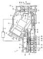
- FIG. 1 is a cross-sectional view showing the vicinity of a combustor in a gas turbine of the present embodiment.
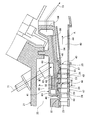
- FIG. 2 is a cross-sectional view showing the vicinity of a blade ring portion of a compressor.
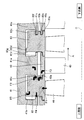
- FIG. 3 is a cross-sectional view taken along the line III-III of FIG. 2 showing a cross section of the blade ring.
- FIG. 4 is a cross-sectional view showing the vicinity of the heat shield ring.
- FIG. 5 is a graph showing the behavior of the clearances of the components of the compressor during hot start of the gas turbine.
- FIG. 6 is a graph showing the behavior of the clearances of the components of the compressor during cold start of the gas turbine.
- FIG. 7 is a schematic diagram showing the entire configuration of a gas turbine.
- FIG. 7 is a schematic view showing the entire configuration of the gas turbine of the present embodiment.
- the gas turbine of this embodiment is comprised by the compressor 11, the combustor 12, and the turbine 13 as shown in FIG.
- a generator (not shown) is coaxially connected to the gas turbine so that power can be generated.
- the compressor 11 has an air inlet 20 for taking in air, and an inlet guide vane (IGV: Inlet Guide Vane) 22 is disposed in the compressor casing 21, and a plurality of stationary blades 23 and a plurality of moving blades 24 are alternately arranged in the flow direction of air (the axial direction of the rotor 32 described later), and a bleed chamber 25 is provided on the outside thereof.
- the compressor 11 compresses the air taken in from the air inlet 20 to generate high-temperature high-pressure compressed air, which is supplied to the casing 14.
- the combustor 12 is supplied with the high-temperature high-pressure compressed air and the fuel which are compressed by the compressor 11 and stored in the casing 14 and burns to generate a combustion gas.
- a plurality of stationary blades 27 and a plurality of moving blades 28 are alternately arranged in the flow direction of the combustion gas (the axial direction of the rotor 32 described later) in the turbine casing 26.
- the exhaust chamber 30 is disposed downstream of the turbine casing 26 via the exhaust casing 29, and the exhaust chamber 30 has an exhaust diffuser 31 connected to the turbine 13. The turbine is driven by the combustion gas from the combustor 12 to drive a coaxially coupled generator.
- a rotor (rotational shaft) 32 is disposed in the compressor 11, the combustor 12 and the turbine 13 so as to penetrate the central portion of the exhaust chamber 30.
- An end of the rotor 32 on the compressor 11 side is rotatably supported by the bearing 33, and an end on the exhaust chamber 30 is rotatably supported by the bearing 34.
- a plurality of disks mounted with the moving blades 24 are stacked and fixed by the compressor 11. Further, in the turbine 13, a plurality of disks mounted with the respective moving blades 28 are stacked and fixed, and a drive shaft of a generator is connected to an end on the exhaust chamber 30 side.
- the compressor casing 21 of the compressor 11 is supported by the legs 35
- the turbine casing 26 of the turbine 13 is supported by the legs 36
- the exhaust chamber 30 is supported by the legs 37. .
- the air taken in from the air intake 20 in the compressor 11 is compressed by passing through the inlet guide vanes 22, the plurality of stationary vanes 23 and the moving vanes 24 to become high temperature / high pressure compressed air. .
- a predetermined fuel is supplied to the compressed air and burns.
- the high temperature / high pressure combustion gas generated in the combustor 12 drives and rotates the rotor 32 by passing through the plurality of stationary blades 27 and the moving blades 28 in the turbine 13, and is connected to the rotor 32.
- the combustion gas is released into the atmosphere after kinetic energy is converted into pressure by the exhaust diffuser 31 of the exhaust chamber 30 and decelerated.
- the clearance between the tip of each moving blade 24 in the compressor 11 and the compressor casing 21 is a clearance (clearance) considering heat expansion of the moving vane 24 and the compressor casing 21 and the like.
- the compression efficiency by the compressor 11 is reduced, and from the viewpoint of the reduction of the performance of the gas turbine itself, the gap between the tip of each moving blade 24 in the compressor 11 and the compressor casing 21 side can be It is desirable to have a small gap.
- the initial gap between the tip of the moving blade 24 and the compressor casing 21 side is enlarged, and the tip of the moving blade 24 in steady operation is properly cooled by appropriately cooling the compressor casing 21 side.
- FIG. 1 is a cross-sectional view showing the vicinity of a combustor in the gas turbine of the present embodiment
- FIG. 2 is a cross-sectional view showing the vicinity of a blade ring of a compressor
- the casing of the present invention is constituted by a compressor casing 21 and a blade ring portion 41.
- the compressor casing 21 having a cylindrical shape around the rotation axis C of the rotor 32 has a cylindrical blade ring portion 41 fixed to the inside thereof, so that the bleed air is extracted between the compressor casing 21 and the blade ring portion 41.
- a chamber 25 is formed.
- the rotor 32 (see FIG. 7) has a plurality of disks 43 integrally connected to the outer peripheral portion, and is rotatably supported by the compressor casing 21 by the bearing 33 (see FIG. 7).
- the plurality of stator vanes 45 and the plurality of buckets 46 are alternately disposed inside the blade ring 41 along the flow direction of the compressed air A.
- the stator blade 45 has a plurality of stator blades 23 arranged at equal intervals in the circumferential direction, and the base end on the rotor 32 side is fixed to the inner shroud 47 having a ring shape, and the tip end on the blade ring 41 is a ring It is configured to be fixed to the outer shroud 48 having a shape.
- the vane body 45 is supported by the wing ring 41 via the outer shroud 48.
- a plurality of moving blades 24 are arranged at equal intervals in the circumferential direction, the base end portion of the moving blade body 46 is fixed to the outer peripheral portion of the disk 43, and the tip end portion faces the inner peripheral surface on the blade ring portion 41 side. It is arranged. In this case, a predetermined clearance (clearance) is secured between the tip of each moving blade 24 and the inner circumferential surface of the blade ring 41.
- a ring-shaped air passage 49 is formed between the blade ring 41 and the inner shroud 47, and a plurality of stator blades 45 and a plurality of moving blades 46 are compressed in the air passage 49. They are alternately arranged along the flow direction of the air A.
- the combustors 12 are disposed at predetermined intervals along the circumferential direction outside the rotor 32 and supported by the turbine casing 26.
- the combustor 12 supplies fuel to the high-temperature high-pressure compressed air A compressed by the compressor 11 and sent from the air passage 49 to the vehicle compartment 14 to burn the combustion gas (exhaust gas).
- a gas passage 51 is formed by a turbine casing 26, and a plurality of stationary blade bodies 52 and a plurality of moving blade bodies 53 are alternately disposed along the flow direction of the exhaust gas G in the gas passage 51. It is done.
- the stator blade 52 has a plurality of stator blades 27 arranged at equal intervals in the circumferential direction, the base end on the rotor 32 side is fixed to the inner shroud 54 having a ring shape, and the tip end on the turbine casing 26 is a ring It is fixed to an outer shroud 55 having a shape.
- the outer shroud 55 of the stationary blade body 52 is supported by the blade ring 56 of the turbine casing 26.
- a plurality of moving blades 28 are spaced apart in the circumferential direction, the base end portion of the moving blade body 53 is fixed to the outer peripheral portion of the disk 57 fixed to the rotor 32, and the tip end portion extends to the blade ring 56 side. It is put out and configured. In this case, a predetermined clearance (clearance) is secured between the tip of each moving blade 28 and the inner circumferential surface of the blade ring 56.
- the compressor 11 faces the tips of the plurality of moving blade bodies 46 (moving blades 24) in the blade ring portion 41, and the inner peripheral surface side of the blade ring portion 41
- the cooling air channel 61 is provided in the The cooling air flow passage 61 is formed as a cavity in the blade ring 41.
- the cooling air flow path 61 includes a plurality of (three in the present embodiment) manifolds 62, 63, 64 arranged at predetermined intervals along the flow direction of the compressed air A in the air passage 49, and the plurality And connecting passages 65 and 66 connecting the manifolds 62, 63 and 64 in series.
- the first manifold 62 formed at the middle position of the flow direction of the compressed air A of the air passage 49 in the blade ring portion 41 as the cooling air flow passage 61 and the compression of the air passage 49 in the blade ring portion 41
- a second manifold 63 is disposed on the upstream side in the flow direction of the air A
- a third manifold 64 is disposed on the downstream side in the flow direction of the compressed air A of the air passage 49 in the blade ring 41.
- the first manifold 62 and the second manifold 63 are connected by the first connection passage 65
- the second manifold 63 and the third manifold 64 are connected by the second connection passage 66.
- each of the manifolds 62, 63, 64 is formed as a hollow portion in a ring shape around the rotation axis C of the rotor 32 in the blade ring portion 41.
- a plurality of first connection passages 65 for connecting the first manifold 62 and the second manifold 63 are formed at predetermined intervals in the circumferential direction on the outer peripheral side of the blade ring portion 41.
- a plurality of second connection passages 66 for connecting the second manifold 63 and the third manifold 64 are formed at predetermined intervals in the circumferential direction on the inner peripheral side of the first connection passage 65 of the blade ring portion 41.
- the first connection passage 65 and the second connection passage 66 are disposed in a staggered manner in the circumferential direction, but may be disposed at the same position in the circumferential direction.
- the compressor 11 extracts a part of the compressed air A from the compartment 14, and supplies the first cooling air supply path 71 to the cooling air channel 61, and A cooler 72 for cooling the compressed air in the first cooling air supply path 71 and a second cooling air supply path 73 for supplying the cooling air in the cooling air flow path 61 to the cooling portion of the turbine 13 are provided.
- a base end portion of the first cooling air supply path 71 is connected to the casing 14, and a tip end portion is connected to the first manifold 62 of the cooling air flow path 61.
- the cooler 72 is provided in the first cooling air supply path 71 and can cool part of the compressed air A.
- the second cooling air supply path 73 is connected at its proximal end to the third manifold 64 and at its distal end to the cooling unit of the turbine 13.
- the cooling portion of the turbine 13 is, for example, the moving blade 28 of the turbine 13, a cooling passage is formed from the disk 57 toward the moving blade 28, and the compressed air A obtained by cooling the blade ring portion 41 is The cooling passage can be supplied from the third manifold 64 by the second cooling air supply passage 73.
- FIG. 4 shows, as an example, the heat shield rings 82 and 83 arranged in a plurality of rows so as to face the axial position of the vanes 45 and the blade 46 arranged in a plurality of rows in the axial direction. There is.
- the flow direction of the compressed air A is indicated by an arrow.
- the following structure of the heat shield ring will be described centering on the heat shield ring 83.
- a support portion 41 a which protrudes inward in the radial direction and is formed in a ring shape around the rotation axis C is formed on the radially inner circumferential side of the blade ring portion 41.
- An upstream edge 41 c and a downstream edge 41 d are formed at the radially inner end of the support 41 a so as to project upstream and downstream in the flow direction of the compressed air A, and the outer shroud 48 of each vane body 45 is formed. It is arranged to face each other.
- blade ring grooves 41b formed so as to be recessed outward in the radial direction are formed.
- heat shield rings 82 and 83 which are formed in a ring shape around the rotation axis C and divided into a plurality of pieces in the circumferential direction, are disposed with a predetermined gap.
- a heat shield ring 83a that is formed at the inner end in the radial direction and protrudes to the upstream side and the downstream side in the axial direction is disposed.
- a fixing portion 83b which is disposed radially outward of the heat shield ring 83a and protrudes to the downstream side in the axial direction, and in the fixing portion radially outside of the fixing portion 83b Sidewall projections 83c are formed parallel to each other and project axially downstream. Furthermore, a lower groove 83e is formed between the heat shield ring 83a and the fixing portion 83b so as to be recessed toward the upstream side in the axial direction, and a space between the side wall protrusion 83c and the fixing portion 83b is formed. An upper groove 83f is formed so as to be recessed in the axial upstream direction and disposed in parallel to the lower groove 83e.
- an upper protruding portion 83 d protruding outward in the radial direction is disposed around the rotation axis C at the axially upstream end of the radially outer peripheral surface of the heat shield ring 83 facing the inner peripheral surface of the blade ring groove 41. Is formed in a ring shape.
- the heat shield ring 82 also has a similar shape.
- a shroud collar portion 48a that protrudes to the upstream side and the downstream side in the axial direction is formed.
- the upstream edge portion 41c of the support portion 41a is inserted into the upper groove 83f of the heat shield ring from the downstream side in the axial direction, and the upstream edge portion 41c of the support portion 41a And from the wing ring 41 via the side wall projection 83c and the fixing portion 83b.
- the shroud ridge portion 48a of the vane body 45 is inserted into the lower groove 83e of the heat shield ring 83 from the downstream side to the upstream side in the axial direction, and the vane body 45 has the shroud ridge portion 48a and the thermal shield ring It is supported from the heat shield ring 83 via the collar part 83a and the fixing part 83b.
- the vane body 45 receives a reaction force in the direction from the downstream side to the upstream side in the axial direction (the direction from the right side to the left side on the paper surface of FIG. 4). Therefore, the outer shroud 48 of the vane body 45 contacts the lower groove 83e of the heat shield ring 83 via the upstream end of the shroud collar portion 48a, and presses the heat shield ring 83 axially upstream.
- the shroud ridge portion 48a of the vane body 45 is inserted into the lower groove 83e formed between the fixing portion 83b and the heat shield ring portion 83a, and the radial movement of the vane body 45 is restrained.
- the upstream edge 41c of the support portion 41a is inserted into the upper groove 83f formed between the fixing portion 83b and the side wall projection 83c, and the radial movement of the heat shield ring 83 is restrained.
- the heat shield ring 83 contacts the radially outer peripheral surface of the upstream edge 41c of the support portion 41a via the radially inner inner peripheral surface of the side wall protrusion 83c on the downstream side in the axial direction Do. Further, on the upstream side in the axial direction, the upstream side wall 83g in the axial direction of the heat shield ring 83 contacts the downstream edge portion 41d of the support portion 41a. In addition, the upper protruding portion 83d of the heat shield ring 83 contacts the blade ring groove 41b on the outer side in the radial direction.
- the heat shield ring is in contact with the blade ring portion only at the above three locations (upstream edge portion 41 c, downstream edge portion 41 d, and upper projecting portion 83 d). It does not contact the entire inner circumferential surface and the axially upstream or downstream inner wall of the blade ring groove 41b.
- the outer shroud 48 of the vane body 45 contacts the heat shield ring 83 via a shroud collar 48 a extending to the upstream side and the downstream side of the outer shroud 48 and a heat shield ring 83 a of the heat shield ring 83. It does not directly contact the wing ring 41.
- the above description has been made focusing on the heat shield ring 83, but the heat shield ring 82 also has a similar structure. Further, the reference numerals of the respective portions of the heat shield ring 82 may be replaced with, for example, the heat shield ring portion 83a of the heat shield ring 83 as the heat shield ring 82a.
- heat transfer from the compressed air A flowing in the air passage 49 to the blade ring portion 41 will be described by taking the heat shield ring 82 as an example. As described above, the transfer of heat from the compressed air A flowing in the air passage 49 to the blade ring 41 is limited to the heat input from the contact portion with the heat shield ring 82.
- the movement of heat from the air passage 49 shown in FIG. 4 is indicated by arrows F1, F2, F3, and F4.
- the heat input to the wing ring portion 41 is the heat input F1 by the heat transfer from the surface facing the air passage 49 side of the inner circumferential surface of the heat shield ring 82 and the heat input F2 by the heat conduction from the stator blade 45 is there.
- the heat shield ring 82 has been described as an example, but the same applies to other heat shield rings.
- a portion of the compressed air A compressed by the compressor 11 is extracted from the compartment 14 and the cooler 72 provided in the first cooling air supply path 71 After being cooled, it is supplied to the cooling air channel 61. That is, in the blade ring portion 41, the low-temperature compressed air A is supplied to the first manifold 62, supplied to the second manifold 63 through the first connection passage 65, and supplied to the third manifold 64 through the second connection passage 66. . Therefore, the blade ring portion 41 is cooled by the cooling air circulated inside, and the temperature increase is suppressed.
- the cooling air that has cooled the blade ring portion 41 is supplied from the third manifold 64 to the cooling portion of the turbine 13 through the second cooling air supply path 73.
- the cooling air flow passage 61 when the passage cross sectional area of each connecting passage 65, 66 is smaller than the passage sectional area of the manifolds 62, 63, 64, when the cooling air passes through each connecting passage 65, 66 The flow velocity rises and the blade ring 41 is effectively cooled.
- the blade ring portion 41 is provided with the heat shield rings 81, 82, 83, 84 on the air passage 49 side, the heat input from the high temperature / high pressure compressed air passing through the air passage 49 is significantly reduced. it can.
- the heat shield rings 81, 82, 83, 84 are divided into a plurality of pieces in the circumferential direction, and are arranged in a ring shape around the rotation axis C with a fixed gap. Therefore, since a certain gap is provided in the circumferential direction, even if the heat shield rings 81, 82, 83, 84 extend in the circumferential direction due to the heat input from the air passage 49 side, the expansion margin in the circumferential direction is obtained. Is absorbed in the gap. Therefore, the radial outward displacement of the heat shield ring hardly occurs, and the radial displacement of the blade ring 41 is not affected.
- FIG. 5 is a graph showing the behavior of the clearance of the components of the compressor during hot start of the gas turbine
- FIG. 6 is a graph showing the behavior of the clearance of the components of the compressor during cold start of the gas turbine.
- the combustor 12 is ignited before the rotational speed of the rotor 32 reaches the rated rotational speed, supplies fuel to the compressed air and burns to generate high temperature / high pressure combustion gas, and the turbine 13 generates combustion gas
- the rotor 32 is driven to rotate by passing through the plurality of stationary blades 27 and moving blades 28. Therefore, at time t3, the load (output) increases at time t3, and reaches a rated load (rated output) at time t4, and is maintained constant.
- the rotating blades 24 are displaced (stretched) radially outward by rotating at high speed, and then receive heat from high temperature / high pressure compressed air passing through the air passage 49. It is further displaced outward (stretched).
- the blade ring portion 41 has a high temperature immediately after the stop, for a certain period of time immediately after the start of the gas turbine, low temperature bleed air is supplied from the compressor 11 to the blade ring portion 41 and is temporarily cooled. Therefore, the blade ring portion 41 temporarily displaces (contracts) radially inward, and thereafter, the temperature of the bleed air from the compressor 11 rises, and the cooling effect of the blade ring portion 41 by the bleed air becomes thin. , Displacing (stretching) outward again.
- the blade ring portion 41 indicated by a dotted line in FIG. 5 is displaced inward by being cooled by low temperature air at time t2, so the tip of the moving blade and the blade ring portion The pinch point where the gap with the inner circumferential surface of the lens temporarily decreases greatly occurs. Thereafter, the blade ring portion is heated by the high temperature and high pressure compressed air and displaced (stretched) to the outside. Then, at time of rated operation after time t4, the blade ring portion is largely displaced to the outside, so the gap between the tip of the moving blade and the inner circumferential surface of the blade ring portion becomes larger than necessary.
- the blade ring portion 41 indicated by a solid line in FIG. 5 is displaced inward by being cooled by low temperature air at time t2, but Since a large gap is maintained between the tip and the inner circumferential surface of the blade ring 41, the gap between the tip of the moving blade 24 and the inner circumferential surface of the blade ring 41 does not decrease as compared with the conventional structure. Then, at the rated operation after time t4, the blade ring portion 41 is cooled by the cooling air supplied to the cooling air flow passage 61, and the high temperature of the air passage 49 by the heat shield rings 81, 82, 83, 84. ⁇ Heat input from high pressure compressed air is suppressed. Therefore, although the blade ring portion 41 is slightly displaced outward, the gap between the tip of the moving blade 24 and the inner circumferential surface of the blade ring portion 41 does not become large as compared with the conventional structure.
- the blade ring 41 is not displaced inward in the radial direction as compared with the time of hot start, so The possibility of occurrence of pinch points is low.
- the gas turbine of the present embodiment includes the compressor 11, the combustor 12, and the turbine 13.
- a compressor casing 21 forming an air passage 49 in a ring shape, a rotor 32 rotatably supported at the center of the compressor casing 21, and a predetermined interval in the axial direction of the outer periphery of the rotor 32 Between the plurality of rotor blades 46 and a plurality of stator vanes fixed to the compressor casing 21 and disposed in the air passage 49.
- the first cooling air supply path 71 for supplying to the path 61, the cooler 72 for cooling the compressed air A of the first cooling air supply path 71, and the cooling air for the cooling air flow path 61 are supplied to the cooling unit of the turbine 13.
- a second cooling air supply path 73 is provided.
- the compressed air A compressed by the compressor 11 is cooled by the cooler 72 and then supplied to the cooling air channel 61, the inner circumferential surface of the compressor casing 21 located outside the air passage 49 is efficiently It can be cooled. Then, since the cooling air obtained by cooling the inner circumferential surface of the compressor casing 21 is supplied to the cooling unit of the turbine 13 and used, the cooling air can be used efficiently.
- a plurality of manifolds 62, 63, 64 arranged at predetermined intervals in the flow direction of air in the air passage 49 and the respective manifolds 62, 63, 64 are provided as the cooling air flow path 61.
- connection passages 65 and 66 connected in series. Therefore, by circulating cooling air between the manifolds 62, 63, 64 through the connecting passages 65, 66 in the compressor casing 21, the outer portions of the plurality of moving blades 46 in the compressor casing 21 can be obtained. It can cool efficiently.
- a third manifold 64 is provided downstream of the flow direction of air and connected to the second cooling air supply path 73, and the first manifold 62 and the second manifold 63 are connected by the first connection passage 65, The second manifold 63 and the third manifold 64 are connected by the second connection passage 66.
- the cooling air supplied to the first manifold 62 by the first cooling air supply path 71 is supplied to the second manifold 63 through the second connection passage 65, and is supplied to the third manifold 64 through the second connection passage 66. It will be discharged by the second cooling air supply path 73. Therefore, the cooling air flows in the blade ring portion 41 in the opposite direction to the compressed air A and then flows in the same direction as the compressed air A. By securing the passage of the cooling air for a long time, a plurality of components in the compressor casing 21 are obtained. The outer portion of the rotor blade 46 can be cooled efficiently.
- a blade annular portion 41 having a cylindrical shape to form the air passage 49 and supporting the outer peripheral portion of the plurality of stator vanes 45 is provided as the compressor casing 21, a blade annular portion 41 having a cylindrical shape to form the air passage 49 and supporting the outer peripheral portion of the plurality of stator vanes 45 is provided. Is formed as a cavity in the wing ring 41. Therefore, it is sufficient to process only the blade ring portion 41 without affecting the configuration of the entire compressor casing 21, and the cooling air flow path 61 can be easily formed.
- the heat shield rings 81, 82, 83, 84 having a structure in which the contact area with the blade ring groove is reduced are provided on the surface of the blade ring 41 facing the air passage 49 side. Therefore, when the high temperature / high pressure compressed air A passes through the air passage 49, the heat shield rings 81, 82, 83, 84 shut off the heat input from the compressed air A to the blade ring portion 41, whereby the blade ring portion The heat input to the blade can be greatly reduced, and the temperature rise of the blade ring can be suppressed, and the radial displacement of the blade ring can be suppressed.
- the heat shield rings 81, 82, 83 are fixed to the inner peripheral portion of the blade ring portion 41 which has a ring shape and faces the outer peripheral side of the plurality of moving blade bodies 46. Therefore, heat input from the compressed air A to the inner circumferential surface of the blade ring 41 facing each moving blade 24 can be effectively blocked by the heat shield rings 81, 82, 83.
- the heat shield ring 84 is fixed. Accordingly, the heat shield ring 84 can effectively block the heat input from the compressed air A having passed through the blade body 46 and the stator body 45 to the inner circumferential surface of the blade ring portion 41.
- the present invention is limited thereto. It is not a thing. That is, the shape, number, formation position, etc. of the manifolds 62, 63, 64 may be appropriately set in accordance with the shape and position of the moving blade 24 and the blade ring portion 41.
Landscapes
- Engineering & Computer Science (AREA)
- Mechanical Engineering (AREA)
- General Engineering & Computer Science (AREA)
- Chemical & Material Sciences (AREA)
- Combustion & Propulsion (AREA)
- Physics & Mathematics (AREA)
- Thermal Sciences (AREA)
- Fluid Mechanics (AREA)
- Structures Of Non-Positive Displacement Pumps (AREA)
- Turbine Rotor Nozzle Sealing (AREA)
Abstract
Description
12 燃焼器
13 タービン
14 車室
21 圧縮機車室
23 静翼
24 動翼
32 ロータ(回転軸)
41 翼環部
41a支持部
45 静翼体
48 外側シュラウド
48aシュラウド鍔部(鍔部)
46 動翼体
49 空気通路
61 冷却空気流路
62 第1マニホールド
63 第2マニホールド
64 第3マニホールド
65 第1連結通路
66 第2連結通路
71 第1冷却空気供給経路
72 冷却器
73 第2冷却空気供給経路
81,82,83,84 遮熱環
C 回転軸線
Claims (7)
- 空気を圧縮する圧縮機と、
前記圧縮機が圧縮した圧縮空気と燃料を混合して燃焼する燃焼器と、
前記燃焼器が生成した燃焼ガスにより回転動力を得るタービンと、
前記空気により回転軸線を中心に回転する回転軸と、
を有するガスタービンにおいて、
前記圧縮機は、
前記回転軸線回りにリング形状をなす空気通路を形成するケーシングと、
前記回転軸の外周部に軸方向に所定間隔をあけて複数固定されて前記空気通路に配置される動翼体と、
前記複数の動翼体の間で前記ケーシングに複数固定されて前記空気通路に配置される複数の静翼体と、
前記複数の動翼体の径方向の外側に対向して設けられ、内部に冷却空気流路が形成された翼環部と、
前記圧縮機が圧縮した圧縮空気の一部を前記冷却空気流路に供給する第1冷却空気供給経路と、
前記冷却空気流路の冷却空気を前記タービンの冷却部に供給する第2冷却空気供給経路と、
を有することを特徴とするガスタービン。 - 前記翼環部は、
径方向内側に突出する前記翼環部の支持部を介して前記翼環部から支持され、回転軸線回りにリング状をなす遮熱環を備え、
前記遮熱環は、前記静翼体の外側シュラウドを介して前記静翼体を支持する鍔部を有することを特徴とする請求項1に記載のガスタービン。 - 前記冷却空気流路は、前記空気通路における空気の流動方向に所定間隔をあけて配置される複数のマニホールドと、前記複数のマニホールドを直列に連結する連結通路とを有することを特徴とする請求項1または請求項2に記載のガスタービン。
- 前記複数のマニホールドは、第1冷却空気供給経路が連結される第1マニホールドと、前記空気通路における空気の流動方向の上流側に配置される第2マニホールドと、前記空気通路における空気の流動方向の下流側に配置されて前記第2冷却空気供給経路が連結される第3マニホールドとを有し、前記連結通路は、前記第1マニホールドと前記第2マニホールドとを連結する第1連結通路と、前記第2マニホールドと前記第3マニホールドとを連結する第2連結通路とを有することを特徴とする請求項3に記載のガスタービン。
- 前記ケーシングは、円筒形状をなして前記空気通路を形成すると共に前記複数の静翼体の外周部を支持する翼環部を有し、前記冷却空気流路は、前記翼環部内に空洞部として形成されることを特徴とする請求項1から請求項4のいずれか一項に記載のガスタービン。
- 前記遮熱環は、周方向に一定の隙間を設けて複数に分割されていることを特徴とする請求項2から請求項5のいずれか一項に記載のガスタービン。
- 前記遮熱環は、前記回転軸線回りにリング形状をなして前記複数の動翼体及び前記複数の静翼体より前記空気通路における圧縮空気の流動方向の下流側における前記翼環部の内周部に固定されることを特徴とする請求項2から請求項6のいずれか一項に記載のガスタービン。
Priority Applications (4)
| Application Number | Priority Date | Filing Date | Title |
|---|---|---|---|
| US15/028,121 US20160251962A1 (en) | 2013-10-15 | 2014-10-10 | Gas turbine |
| CN201480056192.6A CN105637199B (zh) | 2013-10-15 | 2014-10-10 | 燃气轮机 |
| DE112014004738.4T DE112014004738B4 (de) | 2013-10-15 | 2014-10-10 | Gasturbine |
| KR1020167009544A KR101754546B1 (ko) | 2013-10-15 | 2014-10-10 | 가스 터빈 |
Applications Claiming Priority (2)
| Application Number | Priority Date | Filing Date | Title |
|---|---|---|---|
| JP2013214972A JP6223774B2 (ja) | 2013-10-15 | 2013-10-15 | ガスタービン |
| JP2013-214972 | 2013-10-15 |
Publications (1)
| Publication Number | Publication Date |
|---|---|
| WO2015056656A1 true WO2015056656A1 (ja) | 2015-04-23 |
Family
ID=52828100
Family Applications (1)
| Application Number | Title | Priority Date | Filing Date |
|---|---|---|---|
| PCT/JP2014/077262 WO2015056656A1 (ja) | 2013-10-15 | 2014-10-10 | ガスタービン |
Country Status (6)
| Country | Link |
|---|---|
| US (1) | US20160251962A1 (ja) |
| JP (1) | JP6223774B2 (ja) |
| KR (1) | KR101754546B1 (ja) |
| CN (1) | CN105637199B (ja) |
| DE (1) | DE112014004738B4 (ja) |
| WO (1) | WO2015056656A1 (ja) |
Families Citing this family (11)
| Publication number | Priority date | Publication date | Assignee | Title |
|---|---|---|---|---|
| JP5791232B2 (ja) * | 2010-02-24 | 2015-10-07 | 三菱重工航空エンジン株式会社 | 航空用ガスタービン |
| JP6799455B2 (ja) * | 2016-12-16 | 2020-12-16 | 川崎重工業株式会社 | ガスタービンエンジン |
| US10641174B2 (en) * | 2017-01-18 | 2020-05-05 | General Electric Company | Rotor shaft cooling |
| DE102017109952A1 (de) * | 2017-05-09 | 2018-11-15 | Rolls-Royce Deutschland Ltd & Co Kg | Rotorvorrichtung einer Strömungsmaschine |
| JP6925862B2 (ja) * | 2017-05-16 | 2021-08-25 | 三菱パワー株式会社 | ガスタービン、及び翼環部の製造方法 |
| EP3421733B1 (en) * | 2017-06-30 | 2020-02-26 | Ansaldo Energia IP UK Limited | Vane carrier for a gas turbine plant and gas turbine plant comprising said vane carrier |
| JP6963450B2 (ja) | 2017-09-22 | 2021-11-10 | 三菱パワー株式会社 | 回転機械の制御装置、回転機械設備、回転機械の制御方法、及び回転機械の制御プログラム |
| KR101984402B1 (ko) * | 2017-10-24 | 2019-05-30 | 두산중공업 주식회사 | 압축기 및 이를 포함하는 가스터빈 |
| DE102018210598A1 (de) | 2018-06-28 | 2020-01-02 | MTU Aero Engines AG | Gehäusestruktur für eine Strömungsmaschine, Strömungsmaschine und Verfahren zum Kühlen eines Gehäuseabschnitts einer Gehäusestruktur einer Strömungsmaschine |
| JP6651665B1 (ja) * | 2019-03-28 | 2020-02-19 | 三菱日立パワーシステムズ株式会社 | タービン車室、ガスタービン及びタービン車室の変形防止方法 |
| JP6961856B1 (ja) | 2021-06-16 | 2021-11-05 | 三菱パワー株式会社 | タービン組立体及びタービン組立体の組立方法 |
Citations (3)
| Publication number | Priority date | Publication date | Assignee | Title |
|---|---|---|---|---|
| JP2004003492A (ja) * | 2002-05-31 | 2004-01-08 | Mitsubishi Heavy Ind Ltd | ガスタービン圧縮機、及び、ガスタービン圧縮機のクリアランス制御方法 |
| JP2011509372A (ja) * | 2008-01-11 | 2011-03-24 | シーメンス アクチエンゲゼルシヤフト | ガスタービン用圧縮機 |
| JP2011202618A (ja) * | 2010-03-26 | 2011-10-13 | Kawasaki Heavy Ind Ltd | ガスタービンエンジンの圧縮機 |
Family Cites Families (12)
| Publication number | Priority date | Publication date | Assignee | Title |
|---|---|---|---|---|
| FR2683851A1 (fr) * | 1991-11-20 | 1993-05-21 | Snecma | Turbomachine equipee de moyens facilitant le reglage des jeux du stator entree stator et rotor. |
| FR2685936A1 (fr) * | 1992-01-08 | 1993-07-09 | Snecma | Dispositif de controle des jeux d'un carter de compresseur de turbomachine. |
| US5685693A (en) * | 1995-03-31 | 1997-11-11 | General Electric Co. | Removable inner turbine shell with bucket tip clearance control |
| ES2286054T3 (es) * | 2001-04-12 | 2007-12-01 | Siemens Aktiengesellschaft | Turbina de gas con piezas de la carcasa axialmente desplazables. |
| US7434402B2 (en) * | 2005-03-29 | 2008-10-14 | Siemens Power Generation, Inc. | System for actively controlling compressor clearances |
| DE102005045255A1 (de) | 2005-09-22 | 2007-03-29 | Mtu Aero Engines Gmbh | Verbesserter Verdichter in Axialbauart |
| US8602724B2 (en) * | 2009-01-20 | 2013-12-10 | Mitsubishi Heavy Industries, Ltd. | Gas turbine plant |
| US9835171B2 (en) * | 2010-08-20 | 2017-12-05 | Siemens Energy, Inc. | Vane carrier assembly |
| US9458855B2 (en) * | 2010-12-30 | 2016-10-04 | Rolls-Royce North American Technologies Inc. | Compressor tip clearance control and gas turbine engine |
| EP2574732A2 (en) * | 2011-09-29 | 2013-04-03 | Hitachi Ltd. | Gas turbine |
| DE102012215412A1 (de) * | 2012-08-30 | 2014-03-06 | Rolls-Royce Deutschland Ltd & Co Kg | Baugruppe einer Axialturbomaschine und Verfahren zur Herstellung einer solchen Baugruppe |
| US10323524B2 (en) * | 2015-05-08 | 2019-06-18 | United Technologies Corporation | Axial skin core cooling passage for a turbine engine component |
-
2013
- 2013-10-15 JP JP2013214972A patent/JP6223774B2/ja active Active
-
2014
- 2014-10-10 CN CN201480056192.6A patent/CN105637199B/zh active Active
- 2014-10-10 WO PCT/JP2014/077262 patent/WO2015056656A1/ja active Application Filing
- 2014-10-10 DE DE112014004738.4T patent/DE112014004738B4/de active Active
- 2014-10-10 US US15/028,121 patent/US20160251962A1/en not_active Abandoned
- 2014-10-10 KR KR1020167009544A patent/KR101754546B1/ko not_active Application Discontinuation
Patent Citations (3)
| Publication number | Priority date | Publication date | Assignee | Title |
|---|---|---|---|---|
| JP2004003492A (ja) * | 2002-05-31 | 2004-01-08 | Mitsubishi Heavy Ind Ltd | ガスタービン圧縮機、及び、ガスタービン圧縮機のクリアランス制御方法 |
| JP2011509372A (ja) * | 2008-01-11 | 2011-03-24 | シーメンス アクチエンゲゼルシヤフト | ガスタービン用圧縮機 |
| JP2011202618A (ja) * | 2010-03-26 | 2011-10-13 | Kawasaki Heavy Ind Ltd | ガスタービンエンジンの圧縮機 |
Also Published As
| Publication number | Publication date |
|---|---|
| CN105637199A (zh) | 2016-06-01 |
| DE112014004738T5 (de) | 2016-07-14 |
| US20160251962A1 (en) | 2016-09-01 |
| JP6223774B2 (ja) | 2017-11-01 |
| DE112014004738B4 (de) | 2022-12-22 |
| KR101754546B1 (ko) | 2017-07-06 |
| CN105637199B (zh) | 2018-01-26 |
| KR20160055242A (ko) | 2016-05-17 |
| JP2015078622A (ja) | 2015-04-23 |
Similar Documents
| Publication | Publication Date | Title |
|---|---|---|
| WO2015056656A1 (ja) | ガスタービン | |
| JP6223111B2 (ja) | ガスタービン | |
| JP6938610B2 (ja) | クリアランス制御リング組立体 | |
| EP3155233B1 (en) | Gas turbine engine with rotor centering cooling system in an exhaust diffuser | |
| US7785063B2 (en) | Tip clearance control | |
| JP6074176B2 (ja) | ロータ組立体及びそのためのリバーシブルタービンブレードリテーナ | |
| US20130323032A1 (en) | Blade outer air seal for a gas turbine engine | |
| US10443422B2 (en) | Gas turbine engine with a rim seal between the rotor and stator | |
| JP2006307853A (ja) | 軸流流体機械におけるラジアル隙間の調整方法と圧縮機 | |
| JP2015121224A (ja) | ガスタービン用のシールシステム | |
| JP2015078622A5 (ja) | ||
| JP2017110652A (ja) | 活性高圧圧縮機クリアランス制御 | |
| US9816389B2 (en) | Turbine rotor blades with tip portion parapet wall cavities | |
| JP2009191655A (ja) | 軸流圧縮機およびこれを用いたガスタービン | |
| JP2012072708A (ja) | ガスタービンおよびガスタービンの冷却方法 | |
| KR101660679B1 (ko) | 가스터빈의 고온부품, 이를 구비하는 가스터빈, 및 가스터빈의 고온부품 제조방법 | |
| JP4867203B2 (ja) | ガスタービン | |
| US11415010B1 (en) | Turbine nozzle and gas turbine including the same | |
| KR102405750B1 (ko) | 로터 및 이를 포함하는 터보머신 | |
| US11306604B2 (en) | HPC case clearance control thermal control ring spoke system | |
| US10794212B2 (en) | Rotor having improved structure, and turbine and gas turbine including the same | |
| JP2018516330A (ja) | 冷却フィンを備えたケーシングを有するガスタービンエンジン | |
| JP2008144624A (ja) | タービン動翼の固定構造 | |
| JP2024014757A (ja) | 停止用ロータ冷却システム | |
| WO2020046375A1 (en) | Method of operation of inlet heating system for clearance control |
Legal Events
| Date | Code | Title | Description |
|---|---|---|---|
| 121 | Ep: the epo has been informed by wipo that ep was designated in this application |
Ref document number: 14853385 Country of ref document: EP Kind code of ref document: A1 |
|
| WWE | Wipo information: entry into national phase |
Ref document number: 15028121 Country of ref document: US |
|
| ENP | Entry into the national phase |
Ref document number: 20167009544 Country of ref document: KR Kind code of ref document: A |
|
| WWE | Wipo information: entry into national phase |
Ref document number: 1120140047384 Country of ref document: DE Ref document number: 112014004738 Country of ref document: DE |
|
| 122 | Ep: pct application non-entry in european phase |
Ref document number: 14853385 Country of ref document: EP Kind code of ref document: A1 |