EP2236728B1 - Shading device with slats - Google Patents
Shading device with slats Download PDFInfo
- Publication number
- EP2236728B1 EP2236728B1 EP10450043A EP10450043A EP2236728B1 EP 2236728 B1 EP2236728 B1 EP 2236728B1 EP 10450043 A EP10450043 A EP 10450043A EP 10450043 A EP10450043 A EP 10450043A EP 2236728 B1 EP2236728 B1 EP 2236728B1
- Authority
- EP
- European Patent Office
- Prior art keywords
- slats
- guide
- guide slots
- shading device
- flanks
- Prior art date
- Legal status (The legal status is an assumption and is not a legal conclusion. Google has not performed a legal analysis and makes no representation as to the accuracy of the status listed.)
- Not-in-force
Links
Images

Classifications
-
- E—FIXED CONSTRUCTIONS
- E06—DOORS, WINDOWS, SHUTTERS, OR ROLLER BLINDS IN GENERAL; LADDERS
- E06B—FIXED OR MOVABLE CLOSURES FOR OPENINGS IN BUILDINGS, VEHICLES, FENCES OR LIKE ENCLOSURES IN GENERAL, e.g. DOORS, WINDOWS, BLINDS, GATES
- E06B9/00—Screening or protective devices for wall or similar openings, with or without operating or securing mechanisms; Closures of similar construction
- E06B9/24—Screens or other constructions affording protection against light, especially against sunshine; Similar screens for privacy or appearance; Slat blinds
- E06B9/26—Lamellar or like blinds, e.g. venetian blinds
- E06B9/38—Other details
- E06B9/386—Details of lamellae
-
- E—FIXED CONSTRUCTIONS
- E06—DOORS, WINDOWS, SHUTTERS, OR ROLLER BLINDS IN GENERAL; LADDERS
- E06B—FIXED OR MOVABLE CLOSURES FOR OPENINGS IN BUILDINGS, VEHICLES, FENCES OR LIKE ENCLOSURES IN GENERAL, e.g. DOORS, WINDOWS, BLINDS, GATES
- E06B9/00—Screening or protective devices for wall or similar openings, with or without operating or securing mechanisms; Closures of similar construction
- E06B9/24—Screens or other constructions affording protection against light, especially against sunshine; Similar screens for privacy or appearance; Slat blinds
- E06B9/26—Lamellar or like blinds, e.g. venetian blinds
- E06B9/28—Lamellar or like blinds, e.g. venetian blinds with horizontal lamellae, e.g. non-liftable
- E06B9/30—Lamellar or like blinds, e.g. venetian blinds with horizontal lamellae, e.g. non-liftable liftable
- E06B9/303—Lamellar or like blinds, e.g. venetian blinds with horizontal lamellae, e.g. non-liftable liftable with ladder-tape
-
- F—MECHANICAL ENGINEERING; LIGHTING; HEATING; WEAPONS; BLASTING
- F23—COMBUSTION APPARATUS; COMBUSTION PROCESSES
- F23B—METHODS OR APPARATUS FOR COMBUSTION USING ONLY SOLID FUEL
- F23B10/00—Combustion apparatus characterised by the combination of two or more combustion chambers
-
- F—MECHANICAL ENGINEERING; LIGHTING; HEATING; WEAPONS; BLASTING
- F23—COMBUSTION APPARATUS; COMBUSTION PROCESSES
- F23B—METHODS OR APPARATUS FOR COMBUSTION USING ONLY SOLID FUEL
- F23B60/00—Combustion apparatus in which the fuel burns essentially without moving
- F23B60/02—Combustion apparatus in which the fuel burns essentially without moving with combustion air supplied through a grate
-
- F—MECHANICAL ENGINEERING; LIGHTING; HEATING; WEAPONS; BLASTING
- F23—COMBUSTION APPARATUS; COMBUSTION PROCESSES
- F23B—METHODS OR APPARATUS FOR COMBUSTION USING ONLY SOLID FUEL
- F23B80/00—Combustion apparatus characterised by means creating a distinct flow path for flue gases or for non-combusted gases given off by the fuel
- F23B80/04—Combustion apparatus characterised by means creating a distinct flow path for flue gases or for non-combusted gases given off by the fuel by means for guiding the flow of flue gases, e.g. baffles
Definitions
- the invention relates to a shading device with pivotable about its longitudinal axis slats of a wood material, which are displaced along lateral guides of height and having at their ends end guide slots for receiving the guides.
- Slats for shading devices are slidably guided at their ends in height, the guide must allow pivoting of the slats about its longitudinal axis.
- the guide must allow pivoting of the slats about its longitudinal axis.
- stagger the fin ends and provide an axial guide slot in the region of the step, in which engages a preferably rubber-elastic guide web of a voltage applied to the stage guide rail.
- This guide web thus serves on the one hand the slat guide and on the other hand prevents the formation of a gap between the guide rail and the fin ends. Since the guide bar to engage with a comparatively small side play in the frontal guide slot of the slats, a satisfactory pivoting against the pivotal stop forming guide bars can be ensured only for comparatively thin slats, as in metallic slats and plastic slats, but not in for example of the KR 2004 0024083 A known wood slats are the case, which require a thickness sufficient for a sufficient strength, which corresponds to a multiple of the thickness of lamellae made of plastic or metal.
- the invention is therefore based on the object, a shading device of the type described in such a way that slats can be used from a wood material without having to give up a satisfactory pivoting and sufficient lateral guidance of the slats.
- the invention achieves the stated object in that the flanks of the guide slots are inclined in the same direction relative to a lamella standard.
- the slats between the end-side guide slots may have at least one further guide slot aligned with the end-side guide slots with inclined flanks for receiving an intermediate guide. When pivoting the slats, these are thus also supported between the lateral guides on at least one intermediate guide.
- the guide slots with the inclined flanks do not necessarily have to be formed by the wood material of the slats themselves. For reasons of production or for reasons of material properties, it may be useful for the slats to carry inserts with the guide slots having the inclined flanks.
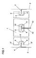
- the shading device shown has a curtain of horizontally extending slats 1, which are held in a conventional manner in Schnurkoln.
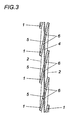
- the provided for pivoting the slats 1 reversible cords 2 of these Schnurscope are in the Fig. 2 and 3 indicated by dash-dotted lines.
- the slats 1 of the curtain are guided along a lateral boundary 3 of a wall opening extending guide 4, in frontal guide slots 5 at the two ends of the slats 1 with lateral Intervene in the game.
- the guides 4 are formed as guide webs, which is not mandatory.
- the guide slots 5 made of a wood material slats 1 have mutually opposite flanks 6, which extend in the same direction inclined relative to a lamella normal (s), namely at an angle ⁇ of 30 ° to 60 °. Due to this inclination of the flanks 6 results for the guide slots 5 is a cross section in the form of a parallelogram having a short diagonal 7 and a long diagonal 8, as shown in the Fig. 2 dash-dotted lines is indicated, in which a blade 1 is shown in a transverse position.
- Fig. 2 results directly determines the length of the short diagonal 7, the lateral movement of the lamellae 1 relative to the guide 4, while the length of the long diagonal 8 limits the maximum pivot angle, as shown in Fig. 3 can be removed, in which the slats 1 are displaced by means of the turning cords 2 in a stop-limited by the guide 4, maximum pivotal position.
- slats 1 For comparatively long slats 1, provision can be made for additional guidance of the slats 1 by means of at least one further guide slit 10 with inclined flanks 6, which is aligned with the end-side guide slots 5, for receiving an intermediate guide 11 is provided, as shown in the Fig. 1 is shown. If this intermediate guide 11 is provided with a web 12 which passes through a transverse slot 13 of the slats 1, then in addition results in a longitudinal guide for the slats 1. For reasons of strength, for example, the guide slots 5 and 10 off-center in a small distance from the transverse slot 13 having longitudinal edge of the slats 1 may be arranged.
Landscapes
- Engineering & Computer Science (AREA)
- Structural Engineering (AREA)
- Physics & Mathematics (AREA)
- Chemical & Material Sciences (AREA)
- Combustion & Propulsion (AREA)
- Thermal Sciences (AREA)
- Mechanical Engineering (AREA)
- General Engineering & Computer Science (AREA)
- Architecture (AREA)
- Civil Engineering (AREA)
- Blinds (AREA)
Description
Die Erfindung bezieht sich auf eine Beschattungsvorrichtung mit um ihre Längsachse verschwenkbaren Lamellen aus einem Holzwerkstoff, die entlang seitlicher Führungen der Höhe nach verlagerbar sind und an ihren Enden stirnseitige Führungsschlitze zur Aufnahme der Führungen aufweisen.The invention relates to a shading device with pivotable about its longitudinal axis slats of a wood material, which are displaced along lateral guides of height and having at their ends end guide slots for receiving the guides.
Lamellen für Beschattungsvorrichtungen, wie Jalousien oder Raffstores, werden an ihren Enden der Höhe nach verschiebbar geführt, wobei die Führung ein Verschwenken der Lamellen um ihre Längsachse ermöglichen muss. Zu diesem Zweck ist es üblich, die Lamellen mit über deren Enden axial vor stehenden Führungsansätzen zu versehen, die in seitliche Führungsschienen eingreifen und eine Schwenkachse für die Lamellen darstellen. Um den damit verbundenen Aufwand zu vermeiden und ein geräuscharmes und klemmfreies Verschwenken der Lamellen zu erlauben ist es darüber hinaus bekannt (
Der Erfindung liegt somit die Aufgabe zugrunde, eine Beschattungsvorrichtung der eingangs geschilderten Art so auszugestalten, dass Lamellen aus einem Holzwerkstoff eingesetzt werden können, ohne auf eine zufriedenstellende Schwenkbarkeit und eine ausreichende Seitenführung der Lamellen verzichten zu müssen.The invention is therefore based on the object, a shading device of the type described in such a way that slats can be used from a wood material without having to give up a satisfactory pivoting and sufficient lateral guidance of the slats.
Die Erfindung löst die gestellte Aufgabe dadurch, dass die Flanken der Führungsschlitze gegenüber einer Lamellennormalen gleichsinnig geneigt verlaufen.The invention achieves the stated object in that the flanks of the guide slots are inclined in the same direction relative to a lamella standard.
Da zufolge der gleichsinnigen, vorzugsweise übereinstimmenden Neigung der einander gegenüberliegenden Flanken der Querschnitt der Führungsschlitze zumindest angenähert einem Parallelogramm entspricht, bestimmen die einander bezüglich der kurzen Diagonale des Querschnittparallelogramms gegenüberliegenden Längsränder der Führungsschlitze das maximale Führungsspiel für die in die Führungsschlitze eingreifenden Führungen, während die einander bezüglich der großen Diagonale gegenüberliegenden Längsränder den maximalen Schwenkwinkel gegenüber den Führungen begrenzen, sodass aufgrund der unterschiedlichen Diagonallängen trotz eines beschränkten seitlichen Führungsspiels ein vergleichsweise großer Schwenkwinkel für die wegen des Holzwerkstoffs verhältnismäßig dicken Lamellen sichergestellt werden kann. Die in die Führungsschlitze eingreifenden Führungen für die Lamellen können unterschiedlich ausfallen und beispielsweise durch einen Führungssteg oder ein Führungsseil gebildet werden.Since, according to the same direction, preferably matching inclination of the opposite flanks of the cross section of the guide slots at least approximately corresponds to a parallelogram determine the opposite each other with respect to the short diagonal of the cross-sectional parallelogram longitudinal edges of the guide slots the maximum guide play for the guide slots engaging in the guides, while the respect The large diagonal opposite longitudinal edges limit the maximum pivot angle relative to the guides, so that due to the different diagonal lengths despite a limited lateral guide clearance, a comparatively large tilt angle for the relatively thick because of the wood material slats can be ensured. The engaging in the guide slots guides for the slats can be different and are formed for example by a guide bar or a guide rope.
Besonders günstige Konstruktionsverhältnisse ergeben sich, wenn die Flanken der Führungsschlitze gegenüber einer Lamellennormalen einen Winkel zwischen 30° und 70° einschließen. Mit zunehmendem Neigungswinkel wird zwar der Längenunterschied der Diagonalen des Querschnittparallelogramms größer, doch empfiehlt sich eine Begrenzung des Neigungswinkels nach oben, damit die einander bezüglich der kurzen Diagonale gegenüberliegenden Längsränder nicht in einer schmalen, bruchanfälligen Schneide auslaufen.Particularly favorable construction conditions arise when the flanks of the guide slots with respect to a lamella normals enclose an angle between 30 ° and 70 °. Although the difference in length of the diagonal of the cross-sectional parallelogram increases with increasing angle of inclination, it is advisable to limit the angle of inclination upward so that the longitudinal edges lying opposite each other with respect to the short diagonal do not run off in a narrow, fracture-prone cutting edge.
Für vergleichsweise lange Lamellen, die mit einem Holzwerkstoff verwirklicht werden können, kann sich eine zusätzliche Führung zur Stabilisierung der Lamellenlage als notwendig erweisen. Zu diesem Zweck können die Lamellen zwischen den endseitigen Führungsschlitzen wenigstens einen weiteren mit den endseitigen Führungsschlitzen fluchtenden Führungsschlitz mit geneigten Flanken zur Aufnahme einer Zwischenführung aufweisen. Beim Verschwenken der Lamellen stützen sich diese somit auch zwischen den seitlichen Führungen an wenigstens einer Zwischenführung ab.For relatively long slats that can be realized with a wood material, an additional guide to stabilize the slat position may prove necessary. For this purpose, the slats between the end-side guide slots may have at least one further guide slot aligned with the end-side guide slots with inclined flanks for receiving an intermediate guide. When pivoting the slats, these are thus also supported between the lateral guides on at least one intermediate guide.
Die Führungsschlitze mit den geneigten Flanken müssen nicht zwingend durch den Holzwerkstoff der Lamellen selbst gebildet werden. Aus Fertigungsgründen bzw. aus Gründen der Materialeigenschaften kann es sinnvoll sein, dass die Lamellen Einsätze mit den die geneigten Flanken aufweisenden Führungsschlitzen tragen.The guide slots with the inclined flanks do not necessarily have to be formed by the wood material of the slats themselves. For reasons of production or for reasons of material properties, it may be useful for the slats to carry inserts with the guide slots having the inclined flanks.
In der Zeichnung ist der Erfindungsgegenstand in einem Ausführungsbeispiel schematisch dargestellt. Es zeigen
- Fig. 1
- eine erfindungsgemäße Beschattungsvorrichtung ausschnittsweise im Bereich eines Lamellenendes in einer Draufsicht,
- Fig. 2
- diese Beschattungsvorrichtung in einem Schnitt nach der Linie II-II der
Fig. 1 in einem größeren Maßstab und - Fig.
- 3 eine dem Schnitt nach der Linie II-II der
Fig. 1 entsprechende Darstel- lung der Beschattungsvorrichtung, jedoch mit einer auf Anschlag ver- schwenkten Lamellenlage.
- Fig. 1
- a shading device according to the invention in sections in the region of a fin end in a plan view,
- Fig. 2
- this shading device in a section along the line II-II of
Fig. 1 on a larger scale and - FIG.
- 3 a section along the line II-II of
Fig. 1 corresponding illustration of the shading device, but with a slat position pivoted to the stop.
Die dargestellte Beschattungsvorrichtung weist einen Behang aus horizontal verlaufenden Lamellen 1 auf, die in herkömmlicher Weise in Schnurzügen gehalten werden. Die zum Schwenken der Lamellen 1 vorgesehenen Wendeschnüre 2 dieser Schnurzüge sind in den
Es zeigt sich somit, dass der Längenunterschied zwischen den kurzen und den langen Diagonalen 7, 8 des Parallelogrammquerschnitts der Führungsschlitze 5 in Verbindung mit der Abmessung der Führung 4 quer zu den Führungsschlitzen 5 und der Dicke der Lamellen 1 das Verhältnis zwischen dem seitlichen Führungsspiel der Führung 4 innerhalb der Führungsschlitze 5 und den maximalen Schwenkwinkel für die Lamellen 1 bestimmen, wobei bei einer entsprechenden Wahl des Winkels α der Neigung der Flanken 6 in Abhängigkeit von der Belastbarkeit der Flankenränder insbesondere im Bereich der schneidenartig zulaufenden Kanten 9 trotz der für die erforderliche Festigkeit notwendigen Dicke der Holzlamellen 1 eine ausreichende Seitenführung der Lamellen 1 gegenüber der Führung 4 und eine gute Verschwenkbarkeit der Lamellen 1 sichergestellt werden kann.It is thus found that the difference in length between the short and
Bei vergleichsweise langen Lamellen 1 kann für eine zusätzliche Führung der Lamellen 1 gesorgt werden, indem zwischen den endseitigen Führungsschlitzen 5 wenigstens ein weiterer mit den endseitigen Führungsschlitzen 5 fluchtender Führungsschlitz 10 mit geneigten Flanken 6 zur Aufnahme einer Zwischenführung 11 vorgesehen wird, wie dies in der
Claims (4)
- Shading device having slats (1) which are pivotable about their longitudinal axis, consist of a timber product, are displaceable in terms of height along lateral guides (4) and comprise end-side guide slots (5) at their ends for receiving the guides (4), characterised in that the flanks (6) of the guide slots (5) extend in an inclined manner in the same direction with respect to a slat normal (n).
- Shading device as claimed in Claim 1, characterised in that the flanks (6) form an angle (α) of between 30° and 70° with respect to a slat normal (n).
- Shading device as claimed in Claim 1 or 2, characterised in that the slats (1) comprise between the end-side guide slots (5) at least one further guide slot (10) aligned with the end-side guide slots (5) and having inclined flanks (6) for receiving an intermediate guide (11).
- Shading device as claimed in any one of Claims 1 to 3, characterised in that the slats (1) support inserts having the guide slots (5) comprising the inclined flanks (6).
Applications Claiming Priority (1)
| Application Number | Priority Date | Filing Date | Title |
|---|---|---|---|
| AT0044809A AT507301B1 (en) | 2009-03-20 | 2009-03-20 | SHADING DEVICE |
Publications (2)
| Publication Number | Publication Date |
|---|---|
| EP2236728A1 EP2236728A1 (en) | 2010-10-06 |
| EP2236728B1 true EP2236728B1 (en) | 2011-11-02 |
Family
ID=42083886
Family Applications (1)
| Application Number | Title | Priority Date | Filing Date |
|---|---|---|---|
| EP10450043A Not-in-force EP2236728B1 (en) | 2009-03-20 | 2010-03-18 | Shading device with slats |
Country Status (2)
| Country | Link |
|---|---|
| EP (1) | EP2236728B1 (en) |
| AT (2) | AT507301B1 (en) |
Families Citing this family (2)
| Publication number | Priority date | Publication date | Assignee | Title |
|---|---|---|---|---|
| JP6598456B2 (en) * | 2014-11-28 | 2019-10-30 | 立川ブラインド工業株式会社 | Horizontal blind |
| NL2016918B1 (en) * | 2016-06-08 | 2017-12-18 | Mare Beheer B V | Venetian blind and method for assembling such a venetian blind |
Family Cites Families (7)
| Publication number | Priority date | Publication date | Assignee | Title |
|---|---|---|---|---|
| DE506199C (en) * | 1930-08-29 | Emil Nicodemus | Board curtain with slits arranged at the ends of the boards for the guide rods and the lift bands | |
| US2170877A (en) * | 1936-12-05 | 1939-08-29 | Lester S Simon | Venetian blind |
| US2324536A (en) * | 1942-01-19 | 1943-07-20 | Transp Equipment Co | Closure structure |
| US2407554A (en) * | 1944-07-05 | 1946-09-10 | Siegfreid G Isserstedt | Blind |
| US2428909A (en) * | 1945-08-21 | 1947-10-14 | Elliott Morris Aubrey | Venetian blind slat |
| KR100568127B1 (en) | 2002-09-13 | 2006-04-05 | 김화순 | Method for manufacturing a slat of blind type using timber portion with gnarls and slat manufactured by the same |
| AT413126B (en) | 2004-03-31 | 2005-11-15 | Kraler Franz | LAMELLE OF A JALOUSIE BZW. A RAFFSTORES |
-
2009
- 2009-03-20 AT AT0044809A patent/AT507301B1/en not_active IP Right Cessation
-
2010
- 2010-03-18 EP EP10450043A patent/EP2236728B1/en not_active Not-in-force
- 2010-03-18 AT AT10450043T patent/ATE531891T1/en active
Also Published As
| Publication number | Publication date |
|---|---|
| ATE531891T1 (en) | 2011-11-15 |
| AT507301B1 (en) | 2010-04-15 |
| AT507301A4 (en) | 2010-04-15 |
| EP2236728A1 (en) | 2010-10-06 |
Similar Documents
| Publication | Publication Date | Title |
|---|---|---|
| AT501706B1 (en) | FLAT KEY AND ASSOCIATED CYLINDER LOCK | |
| EP0153558A2 (en) | Assembly kit for fabricating a lamella of a lamellar blind | |
| DE10033388A1 (en) | Insulated composite profile, especially for windows, doors, facades and the like | |
| EP2236728B1 (en) | Shading device with slats | |
| DE2812128C3 (en) | Heat-insulating profile body | |
| EP0016958B1 (en) | Frame section for a window, a door or the like | |
| EP2182155A2 (en) | Scissor mechanism | |
| DE2935158B2 (en) | Extruded component for building walls, in particular of motor vehicles | |
| DE3235609C2 (en) | ||
| DE3439782C2 (en) | Door leaf | |
| EP3112577B1 (en) | Drop-down seal | |
| EP2154324A2 (en) | Endpiece with hinge function for roller shutter profiles and roller shutter | |
| DE19852133A1 (en) | Distance piece for linked power supply conduit assemblies consists of two parallel, strip-shaped parts extending between cross-pieces that can be locked together via latching arrangements | |
| DE102017006298A1 (en) | Profiled metal fiber | |
| EP3591140B1 (en) | Heavy duty bolt, scaffold, method for producing a heavy duty bolt, method for manufacturing a scaffold | |
| AT306335B (en) | Venetian blind | |
| DE2501066A1 (en) | SHUTTERS | |
| EP3153891B1 (en) | Gate with length-adjustable spacer and method for assembly of this gate | |
| DE2928751A1 (en) | Tent type support frame truss connection - involves interlocking T=shaped arm and groove on fitting form pieces | |
| DE1778671A1 (en) | Frameless ventilation grille | |
| DE202015004601U1 (en) | Slat for external blinds | |
| AT298759B (en) | ROLLER SHUTTER PROFILE BAR | |
| EP1983140B1 (en) | Connector | |
| DE2625662C3 (en) | Locking member against longitudinal displacement of adjacent, hook-shaped interlocking hollow profile slats of a roller shutter | |
| DE102018216941A1 (en) | Wooden panel and method of making a wooden panel |
Legal Events
| Date | Code | Title | Description |
|---|---|---|---|
| PUAI | Public reference made under article 153(3) epc to a published international application that has entered the european phase |
Free format text: ORIGINAL CODE: 0009012 |
|
| AK | Designated contracting states |
Kind code of ref document: A1 Designated state(s): AT BE BG CH CY CZ DE DK EE ES FI FR GB GR HR HU IE IS IT LI LT LU LV MC MK MT NL NO PL PT RO SE SI SK SM TR |
|
| AX | Request for extension of the european patent |
Extension state: AL BA ME RS |
|
| 17P | Request for examination filed |
Effective date: 20110310 |
|
| GRAP | Despatch of communication of intention to grant a patent |
Free format text: ORIGINAL CODE: EPIDOSNIGR1 |
|
| RIC1 | Information provided on ipc code assigned before grant |
Ipc: E06B 9/327 20060101AFI20110421BHEP |
|
| GRAS | Grant fee paid |
Free format text: ORIGINAL CODE: EPIDOSNIGR3 |
|
| GRAA | (expected) grant |
Free format text: ORIGINAL CODE: 0009210 |
|
| AK | Designated contracting states |
Kind code of ref document: B1 Designated state(s): AT BE BG CH CY CZ DE DK EE ES FI FR GB GR HR HU IE IS IT LI LT LU LV MC MK MT NL NO PL PT RO SE SI SK SM TR |
|
| REG | Reference to a national code |
Ref country code: GB Ref legal event code: FG4D Free format text: NOT ENGLISH |
|
| REG | Reference to a national code |
Ref country code: CH Ref legal event code: EP |
|
| REG | Reference to a national code |
Ref country code: IE Ref legal event code: FG4D |
|
| REG | Reference to a national code |
Ref country code: DE Ref legal event code: R096 Ref document number: 502010000201 Country of ref document: DE Effective date: 20111229 |
|
| REG | Reference to a national code |
Ref country code: CH Ref legal event code: NV Representative=s name: PATENTANWALTSBUERO STEUDTNER |
|
| REG | Reference to a national code |
Ref country code: NL Ref legal event code: VDEP Effective date: 20111102 |
|
| LTIE | Lt: invalidation of european patent or patent extension |
Effective date: 20111102 |
|
| PG25 | Lapsed in a contracting state [announced via postgrant information from national office to epo] |
Ref country code: IS Free format text: LAPSE BECAUSE OF FAILURE TO SUBMIT A TRANSLATION OF THE DESCRIPTION OR TO PAY THE FEE WITHIN THE PRESCRIBED TIME-LIMIT Effective date: 20120302 Ref country code: LT Free format text: LAPSE BECAUSE OF FAILURE TO SUBMIT A TRANSLATION OF THE DESCRIPTION OR TO PAY THE FEE WITHIN THE PRESCRIBED TIME-LIMIT Effective date: 20111102 Ref country code: NO Free format text: LAPSE BECAUSE OF FAILURE TO SUBMIT A TRANSLATION OF THE DESCRIPTION OR TO PAY THE FEE WITHIN THE PRESCRIBED TIME-LIMIT Effective date: 20120202 |
|
| PG25 | Lapsed in a contracting state [announced via postgrant information from national office to epo] |
Ref country code: PL Free format text: LAPSE BECAUSE OF FAILURE TO SUBMIT A TRANSLATION OF THE DESCRIPTION OR TO PAY THE FEE WITHIN THE PRESCRIBED TIME-LIMIT Effective date: 20111102 Ref country code: HR Free format text: LAPSE BECAUSE OF FAILURE TO SUBMIT A TRANSLATION OF THE DESCRIPTION OR TO PAY THE FEE WITHIN THE PRESCRIBED TIME-LIMIT Effective date: 20111102 Ref country code: SI Free format text: LAPSE BECAUSE OF FAILURE TO SUBMIT A TRANSLATION OF THE DESCRIPTION OR TO PAY THE FEE WITHIN THE PRESCRIBED TIME-LIMIT Effective date: 20111102 Ref country code: GR Free format text: LAPSE BECAUSE OF FAILURE TO SUBMIT A TRANSLATION OF THE DESCRIPTION OR TO PAY THE FEE WITHIN THE PRESCRIBED TIME-LIMIT Effective date: 20120203 Ref country code: LV Free format text: LAPSE BECAUSE OF FAILURE TO SUBMIT A TRANSLATION OF THE DESCRIPTION OR TO PAY THE FEE WITHIN THE PRESCRIBED TIME-LIMIT Effective date: 20111102 Ref country code: NL Free format text: LAPSE BECAUSE OF FAILURE TO SUBMIT A TRANSLATION OF THE DESCRIPTION OR TO PAY THE FEE WITHIN THE PRESCRIBED TIME-LIMIT Effective date: 20111102 Ref country code: PT Free format text: LAPSE BECAUSE OF FAILURE TO SUBMIT A TRANSLATION OF THE DESCRIPTION OR TO PAY THE FEE WITHIN THE PRESCRIBED TIME-LIMIT Effective date: 20120302 Ref country code: SE Free format text: LAPSE BECAUSE OF FAILURE TO SUBMIT A TRANSLATION OF THE DESCRIPTION OR TO PAY THE FEE WITHIN THE PRESCRIBED TIME-LIMIT Effective date: 20111102 |
|
| REG | Reference to a national code |
Ref country code: IE Ref legal event code: FD4D |
|
| PG25 | Lapsed in a contracting state [announced via postgrant information from national office to epo] |
Ref country code: CY Free format text: LAPSE BECAUSE OF FAILURE TO SUBMIT A TRANSLATION OF THE DESCRIPTION OR TO PAY THE FEE WITHIN THE PRESCRIBED TIME-LIMIT Effective date: 20111102 |
|
| PG25 | Lapsed in a contracting state [announced via postgrant information from national office to epo] |
Ref country code: CZ Free format text: LAPSE BECAUSE OF FAILURE TO SUBMIT A TRANSLATION OF THE DESCRIPTION OR TO PAY THE FEE WITHIN THE PRESCRIBED TIME-LIMIT Effective date: 20111102 Ref country code: DK Free format text: LAPSE BECAUSE OF FAILURE TO SUBMIT A TRANSLATION OF THE DESCRIPTION OR TO PAY THE FEE WITHIN THE PRESCRIBED TIME-LIMIT Effective date: 20111102 Ref country code: SK Free format text: LAPSE BECAUSE OF FAILURE TO SUBMIT A TRANSLATION OF THE DESCRIPTION OR TO PAY THE FEE WITHIN THE PRESCRIBED TIME-LIMIT Effective date: 20111102 Ref country code: EE Free format text: LAPSE BECAUSE OF FAILURE TO SUBMIT A TRANSLATION OF THE DESCRIPTION OR TO PAY THE FEE WITHIN THE PRESCRIBED TIME-LIMIT Effective date: 20111102 Ref country code: IE Free format text: LAPSE BECAUSE OF FAILURE TO SUBMIT A TRANSLATION OF THE DESCRIPTION OR TO PAY THE FEE WITHIN THE PRESCRIBED TIME-LIMIT Effective date: 20111102 Ref country code: BG Free format text: LAPSE BECAUSE OF FAILURE TO SUBMIT A TRANSLATION OF THE DESCRIPTION OR TO PAY THE FEE WITHIN THE PRESCRIBED TIME-LIMIT Effective date: 20120202 |
|
| PG25 | Lapsed in a contracting state [announced via postgrant information from national office to epo] |
Ref country code: RO Free format text: LAPSE BECAUSE OF FAILURE TO SUBMIT A TRANSLATION OF THE DESCRIPTION OR TO PAY THE FEE WITHIN THE PRESCRIBED TIME-LIMIT Effective date: 20111102 Ref country code: IT Free format text: LAPSE BECAUSE OF FAILURE TO SUBMIT A TRANSLATION OF THE DESCRIPTION OR TO PAY THE FEE WITHIN THE PRESCRIBED TIME-LIMIT Effective date: 20111102 |
|
| PLBE | No opposition filed within time limit |
Free format text: ORIGINAL CODE: 0009261 |
|
| STAA | Information on the status of an ep patent application or granted ep patent |
Free format text: STATUS: NO OPPOSITION FILED WITHIN TIME LIMIT |
|
| BERE | Be: lapsed |
Owner name: RANKL, GERALD Effective date: 20120331 |
|
| 26N | No opposition filed |
Effective date: 20120803 |
|
| PG25 | Lapsed in a contracting state [announced via postgrant information from national office to epo] |
Ref country code: MC Free format text: LAPSE BECAUSE OF NON-PAYMENT OF DUE FEES Effective date: 20120331 |
|
| REG | Reference to a national code |
Ref country code: DE Ref legal event code: R097 Ref document number: 502010000201 Country of ref document: DE Effective date: 20120803 |
|
| PG25 | Lapsed in a contracting state [announced via postgrant information from national office to epo] |
Ref country code: BE Free format text: LAPSE BECAUSE OF NON-PAYMENT OF DUE FEES Effective date: 20120331 |
|
| PG25 | Lapsed in a contracting state [announced via postgrant information from national office to epo] |
Ref country code: MK Free format text: LAPSE BECAUSE OF FAILURE TO SUBMIT A TRANSLATION OF THE DESCRIPTION OR TO PAY THE FEE WITHIN THE PRESCRIBED TIME-LIMIT Effective date: 20111102 |
|
| PG25 | Lapsed in a contracting state [announced via postgrant information from national office to epo] |
Ref country code: ES Free format text: LAPSE BECAUSE OF FAILURE TO SUBMIT A TRANSLATION OF THE DESCRIPTION OR TO PAY THE FEE WITHIN THE PRESCRIBED TIME-LIMIT Effective date: 20120213 |
|
| PG25 | Lapsed in a contracting state [announced via postgrant information from national office to epo] |
Ref country code: FI Free format text: LAPSE BECAUSE OF FAILURE TO SUBMIT A TRANSLATION OF THE DESCRIPTION OR TO PAY THE FEE WITHIN THE PRESCRIBED TIME-LIMIT Effective date: 20111102 |
|
| PG25 | Lapsed in a contracting state [announced via postgrant information from national office to epo] |
Ref country code: MT Free format text: LAPSE BECAUSE OF FAILURE TO SUBMIT A TRANSLATION OF THE DESCRIPTION OR TO PAY THE FEE WITHIN THE PRESCRIBED TIME-LIMIT Effective date: 20111102 |
|
| PG25 | Lapsed in a contracting state [announced via postgrant information from national office to epo] |
Ref country code: TR Free format text: LAPSE BECAUSE OF FAILURE TO SUBMIT A TRANSLATION OF THE DESCRIPTION OR TO PAY THE FEE WITHIN THE PRESCRIBED TIME-LIMIT Effective date: 20111102 |
|
| PG25 | Lapsed in a contracting state [announced via postgrant information from national office to epo] |
Ref country code: LU Free format text: LAPSE BECAUSE OF NON-PAYMENT OF DUE FEES Effective date: 20120318 Ref country code: SM Free format text: LAPSE BECAUSE OF FAILURE TO SUBMIT A TRANSLATION OF THE DESCRIPTION OR TO PAY THE FEE WITHIN THE PRESCRIBED TIME-LIMIT Effective date: 20111102 |
|
| PG25 | Lapsed in a contracting state [announced via postgrant information from national office to epo] |
Ref country code: HU Free format text: LAPSE BECAUSE OF FAILURE TO SUBMIT A TRANSLATION OF THE DESCRIPTION OR TO PAY THE FEE WITHIN THE PRESCRIBED TIME-LIMIT Effective date: 20100318 |
|
| REG | Reference to a national code |
Ref country code: CH Ref legal event code: PCAR Free format text: NEW ADDRESS: ALBULAGASSE 8, 5200 BRUGG/AG (CH) |
|
| PGFP | Annual fee paid to national office [announced via postgrant information from national office to epo] |
Ref country code: FR Payment date: 20140328 Year of fee payment: 5 |
|
| REG | Reference to a national code |
Ref country code: CH Ref legal event code: PL |
|
| GBPC | Gb: european patent ceased through non-payment of renewal fee |
Effective date: 20140318 |
|
| PG25 | Lapsed in a contracting state [announced via postgrant information from national office to epo] |
Ref country code: GB Free format text: LAPSE BECAUSE OF NON-PAYMENT OF DUE FEES Effective date: 20140318 Ref country code: LI Free format text: LAPSE BECAUSE OF NON-PAYMENT OF DUE FEES Effective date: 20140331 Ref country code: CH Free format text: LAPSE BECAUSE OF NON-PAYMENT OF DUE FEES Effective date: 20140331 |
|
| PGFP | Annual fee paid to national office [announced via postgrant information from national office to epo] |
Ref country code: DE Payment date: 20150402 Year of fee payment: 6 |
|
| REG | Reference to a national code |
Ref country code: FR Ref legal event code: ST Effective date: 20151130 |
|
| PG25 | Lapsed in a contracting state [announced via postgrant information from national office to epo] |
Ref country code: FR Free format text: LAPSE BECAUSE OF NON-PAYMENT OF DUE FEES Effective date: 20150331 |
|
| REG | Reference to a national code |
Ref country code: AT Ref legal event code: MM01 Ref document number: 531891 Country of ref document: AT Kind code of ref document: T Effective date: 20150318 |
|
| PG25 | Lapsed in a contracting state [announced via postgrant information from national office to epo] |
Ref country code: AT Free format text: LAPSE BECAUSE OF NON-PAYMENT OF DUE FEES Effective date: 20150318 |
|
| REG | Reference to a national code |
Ref country code: DE Ref legal event code: R119 Ref document number: 502010000201 Country of ref document: DE |
|
| PG25 | Lapsed in a contracting state [announced via postgrant information from national office to epo] |
Ref country code: DE Free format text: LAPSE BECAUSE OF NON-PAYMENT OF DUE FEES Effective date: 20161001 |