EP2236416A2 - Payload quick release for an aerial system - Google Patents
Payload quick release for an aerial system Download PDFInfo
- Publication number
- EP2236416A2 EP2236416A2 EP10151254A EP10151254A EP2236416A2 EP 2236416 A2 EP2236416 A2 EP 2236416A2 EP 10151254 A EP10151254 A EP 10151254A EP 10151254 A EP10151254 A EP 10151254A EP 2236416 A2 EP2236416 A2 EP 2236416A2
- Authority
- EP
- European Patent Office
- Prior art keywords
- payload
- plane
- attachment
- arm
- section
- Prior art date
- Legal status (The legal status is an assumption and is not a legal conclusion. Google has not performed a legal analysis and makes no representation as to the accuracy of the status listed.)
- Withdrawn
Links
- 230000007246 mechanism Effects 0.000 claims abstract description 51
- 238000000034 method Methods 0.000 claims description 9
- 230000000994 depressogenic effect Effects 0.000 claims description 4
- 238000003825 pressing Methods 0.000 claims description 3
- 230000000881 depressing effect Effects 0.000 claims description 2
- 230000007704 transition Effects 0.000 claims 1
- 230000000712 assembly Effects 0.000 description 2
- 238000000429 assembly Methods 0.000 description 2
- 230000002411 adverse Effects 0.000 description 1
- 238000002485 combustion reaction Methods 0.000 description 1
- 239000002131 composite material Substances 0.000 description 1
- 230000010006 flight Effects 0.000 description 1
- 230000033001 locomotion Effects 0.000 description 1
- 239000000463 material Substances 0.000 description 1
- 239000002184 metal Substances 0.000 description 1
- 239000007769 metal material Substances 0.000 description 1
- 230000000717 retained effect Effects 0.000 description 1
- 239000011435 rock Substances 0.000 description 1
- 230000002459 sustained effect Effects 0.000 description 1
Images


Classifications
-
- B—PERFORMING OPERATIONS; TRANSPORTING
- B64—AIRCRAFT; AVIATION; COSMONAUTICS
- B64D—EQUIPMENT FOR FITTING IN OR TO AIRCRAFT; FLIGHT SUITS; PARACHUTES; ARRANGEMENT OR MOUNTING OF POWER PLANTS OR PROPULSION TRANSMISSIONS IN AIRCRAFT
- B64D1/00—Dropping, ejecting, releasing or receiving articles, liquids, or the like, in flight
- B64D1/02—Dropping, ejecting, or releasing articles
-
- B—PERFORMING OPERATIONS; TRANSPORTING
- B64—AIRCRAFT; AVIATION; COSMONAUTICS
- B64U—UNMANNED AERIAL VEHICLES [UAV]; EQUIPMENT THEREFOR
- B64U10/00—Type of UAV
- B64U10/10—Rotorcrafts
- B64U10/13—Flying platforms
-
- B—PERFORMING OPERATIONS; TRANSPORTING
- B64—AIRCRAFT; AVIATION; COSMONAUTICS
- B64U—UNMANNED AERIAL VEHICLES [UAV]; EQUIPMENT THEREFOR
- B64U20/00—Constructional aspects of UAVs
- B64U20/70—Constructional aspects of the UAV body
-
- B—PERFORMING OPERATIONS; TRANSPORTING
- B64—AIRCRAFT; AVIATION; COSMONAUTICS
- B64U—UNMANNED AERIAL VEHICLES [UAV]; EQUIPMENT THEREFOR
- B64U30/00—Means for producing lift; Empennages; Arrangements thereof
- B64U30/20—Rotors; Rotor supports
- B64U30/26—Ducted or shrouded rotors
-
- B—PERFORMING OPERATIONS; TRANSPORTING
- B64—AIRCRAFT; AVIATION; COSMONAUTICS
- B64U—UNMANNED AERIAL VEHICLES [UAV]; EQUIPMENT THEREFOR
- B64U50/00—Propulsion; Power supply
- B64U50/10—Propulsion
- B64U50/11—Propulsion using internal combustion piston engines
-
- F—MECHANICAL ENGINEERING; LIGHTING; HEATING; WEAPONS; BLASTING
- F16—ENGINEERING ELEMENTS AND UNITS; GENERAL MEASURES FOR PRODUCING AND MAINTAINING EFFECTIVE FUNCTIONING OF MACHINES OR INSTALLATIONS; THERMAL INSULATION IN GENERAL
- F16B—DEVICES FOR FASTENING OR SECURING CONSTRUCTIONAL ELEMENTS OR MACHINE PARTS TOGETHER, e.g. NAILS, BOLTS, CIRCLIPS, CLAMPS, CLIPS OR WEDGES; JOINTS OR JOINTING
- F16B21/00—Means for preventing relative axial movement of a pin, spigot, shaft or the like and a member surrounding it; Stud-and-socket releasable fastenings
- F16B21/02—Releasable fastening devices locking by rotation
-
- B—PERFORMING OPERATIONS; TRANSPORTING
- B64—AIRCRAFT; AVIATION; COSMONAUTICS
- B64U—UNMANNED AERIAL VEHICLES [UAV]; EQUIPMENT THEREFOR
- B64U2101/00—UAVs specially adapted for particular uses or applications
- B64U2101/60—UAVs specially adapted for particular uses or applications for transporting passengers; for transporting goods other than weapons
Definitions
- the present disclosure relates generally to aerial vehicles.
- Unmanned aerial vehicles are remotely piloted or self-piloted aircraft that can carry cameras, sensors, communications equipment, or other payloads.
- a UAV is capable of controlled, sustained flight and is often powered by either a gas turbine or a reciprocating internal combustion engine.
- the UAVs may be remotely controlled or may fly autonomously based on pre-programmed flight plans or more complex dynamic automation systems.
- UAVs have become increasingly used for various applications where the use of manned flight vehicles is not appropriate or is not feasible.
- Such applications may include military situations, such as surveillance, reconnaissance, target acquisition, data acquisition, communications relay, decoy, harassment, or supply flights.
- military situations such as surveillance, reconnaissance, target acquisition, data acquisition, communications relay, decoy, harassment, or supply flights.
- These vehicles are also used in a growing number of civilian applications, such as firefighting when a human observer would be at risk, police observation of civil disturbances or crime scenes, reconnaissance support in natural disasters, and scientific research, such as collecting data from within a hurricane.
- UAVs often carry payloads.
- UAVs are the delivery system for a payload.
- payloads are typically held on to a UAV with bolt/washer/locknut assemblies. These assemblies make it difficult to remove and replace the payload, especially at night when visibility is poor.
- Handling the bolts, washers, and locknuts demands dexterity, and often, even a skilled assembler drops parts, loses them, or otherwise experiences difficulty. The result is increased time to assemble a payload to a UAV and inconsistent assembly quality. In combat or other adverse situations, increased time to assemble a payload to a UAV can prove harmful for the assembler.
- the disclosure is directed to an aerial vehicle that includes a payload quick release mechanism. This mechanism improves the ability to quickly attach and remove a payload from an aerial vehicle.
- an attachment device comprising a body with a perimeter and a plurality of arms that extend from the body perimeter. Each arm comprises a first section extending from the body perimeter and a second section that extends at a non-zero angle from the first section.
- a method for attaching a payload to an unmanned aerial vehicle comprises affixing an attachment mechanism to the unmanned aerial vehicle, pressing a payload against the attachment mechanism, rotating the payload while maintaining pressure against the attachment mechanism, until a payload tab on the payload slides over an arm of the attachment mechanism and into an indented portion in the arm, and finally locking the payload tab into a position within the indented portion of the arm of the attachment mechanism.
- a bayonet style quick release mechanism comprises a body that is affixed to an unmanned aerial vehicle.
- the body comprises a plurality of arm members.
- Each arm member has a proximate end that is affixed to the body and a distal end.
- Each of the plurality of arm members comprises a section sized to receive a payload tab, and a lip at the distal end that is raised above the section.
- the payload tab extends from the top surface of a payload.
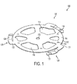
- Figure 1 depicts a perspective view of a payload quick release mechanism according to one embodiment of the invention.
- the payload quick release mechanism 100 includes a body 110 and a plurality of arms 120.
- Body 110 comprises a perimeter 112. Although a circular perimeter is shown in Figure 1 , perimeter 112 is not limited to a circular shape and various other shapes may be contemplated.
- Body 110 may be shaped to fit to an aerial system such as an unmanned aerial vehicle (UAV) structure, or a payload present on the UAV.
- UAV unmanned aerial vehicle
- the UAV may be a ducted fan UAV. In the alternative, the UAV may not comprise a ducted fan.
- Body 110 may comprise a plurality of attachment holes 114 and a plurality of cutouts 116. Attachment holes 114 may be present to affix payload quick release mechanism 100 to a UAV structure on the UAV with attachment devices such as screws. Cutouts 116 may be present to decrease the weight of body 110, or for access to the structure to which payload quick release mechanism 100 is attached.
- Each of the plurality of arms 120 comprises a proximate end 121 and a distal end 123. Proximate end 121 may be attached to perimeter 112. In this embodiment, each arm would extend from perimeter 112. In an alternative embodiment, each arm may be formed near the center of body 110 instead of the perimeter 112, to accommodate a payload with a smaller perimeter than the quick release mechanism.
- Each of the plurality of arms 120 may be manufactured separate from body 110, and may be attached to body 110 prior to use. In the alternative, each of the plurality of arms 120 may be manufactured as part of body 110.
- Each arm of the plurality of arms 120 comprises a first section 122 and a second section 124. First section 122 may extend substantially orthogonally from body perimeter 112. Second section 124 may extend at a non-zero angle from first section 122.
- Payload quick release mechanism 100 may be made from a plastic or a composite material and may be molded into shape. In the alternative, payload quick release mechanism 100 may be machined using a variety of plastic or metal materials. As another alternative, payload quick release mechanism 100 may be made from a formed metal. Once the basic shape of payload quick release mechanism 100 is manufactured, any finishing cutouts 116 or attachment holes 114 may be machined into the part.
- FIG. 2 illustrates an enlarged view of second section 124 of the payload quick release mechanism 100 of Figure 1 .
- Second section 124 may comprise a bayonet-style locking feature.
- the second section 124 may comprise a first portion 130 on a first plane, a second portion 132 on a second plane, a third portion 134 that extends between the first plane and the second plane, a fourth portion 136 on a third plane, and a fifth portion 138 that extends between the second plane and the third plane.
- the second plane may be substantially parallel to the first plane. In an alternative embodiment, the second plane may not be parallel to the first plane.
- the third plane may not be parallel to either the first plane or the second plane.
- Fourth portion 136 comprises a top surface 137.
- the locking feature may comprise an arm that comprises an indent and a lip, wherein the indent is second portion 132 and the lip is fourth portion 136 as shown in Figure 2 .
- the entirety of the lip may not lie on the third plane, but may instead be slanted at an angle such that part of the lip or fourth portion 136 dips below the third plane.
- the arm 120, or any portion thereof may be manufactured from a material that has a natural resiliency, thus the arm 120, or any portion thereof, has the ability not only to give way and move under exerted pressure, but to return to its original position after the pressure exerted is removed.
- the indent may be sized to receive a payload tab.
- the indent is preferably sized to provide a snug fit on either side of the payload tab, and not allow for the payload tab to translate.
- FIG 3 is a perspective view of a payload quick release mechanism 200 with a radial centering feature 210.
- Radial centering feature 210 may be a stepped ring, as shown. Radial centering feature 210 aides in the proper alignment of a payload with payload quick release mechanism 100. This is accomplished by providing radial alignment between the two pieces. Radial centering feature 210 may be manufactured as part of payload quick release mechanism 200 or as a separate piece.
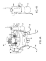
- FIG 4a is an exemplary embodiment of a payload quick release mechanism on a UAV 300
- Figure 4b is an enlarged view of the structure with the payload attached from Figure 4a
- UAV 300 may comprise a payload 310, a structure 320 to which the payload attaches, an air duct 330, engine cylinders 350, control vanes 360, landing gear 370, and a payload quick release mechanism 380.
- Structure 320 may be a pod, as shown in Figure 4b . However, structure 320 is not limited to a pod, and may be another structure on the aerial vehicle.
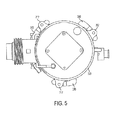
- Payload 310 comprises a plurality of payload tabs 312, as shown in Figure 5 , in a top view of the payload and pod configuration of Figure 4B .
- Payload tabs 312 may extend substantially orthogonally from the top surface of payload 310.
- Payload quick release mechanism 380 is designed to have a sliding fit against payload tabs 312, as shown in Figure 5 when payload 310 is affixed to structure 320 via payload quick release mechanism 380.
- payload quick release mechanism 380 is affixed to structure 320.
- Payload quick release mechanism 380 may be affixed to structure 320 by inserting screws, rivets, or other attachment mechanisms through attachment holes 114 and actuating the attachment mechanism.
- Payload 310 is then pressed against payload quick release mechanism 380 and is rotated.
- each of the plurality of payload tabs 312 applies pressure to top surface 137 of fourth portion 136, depressing arms 120.
- the payload tab 312 slides over the depressed fourth portion 136 and continues to move toward second portion 132 as the payload continues to rotate.
- a user may depress fourth portion 136 to overcome the spring force of arm 120.
- Payload tab 312 may then be slidingly removed from its position on second portion 132 by rotating the payload in the opposite direction from which it was inserted, effectively reversing the locking turn. That is, fourth portion 136 is depressed to permit removal of the payload from payload quick release mechanism.
- This system and method for the assembly and removal of a payload is a simpler procedure than ones in which a user must attach the payload with screws, washers, and locknuts. The risk of losing a part in either the assembly or removal process is mitigated. In addition, the processes afforded by the mechanism for attachment and removal of a payload are quicker to implement than traditional assembly and removal methods, saving a user time.
Landscapes
- Engineering & Computer Science (AREA)
- Aviation & Aerospace Engineering (AREA)
- Mechanical Engineering (AREA)
- Remote Sensing (AREA)
- General Engineering & Computer Science (AREA)
- Chemical & Material Sciences (AREA)
- Combustion & Propulsion (AREA)
- Forklifts And Lifting Vehicles (AREA)
- Toys (AREA)
Applications Claiming Priority (1)
| Application Number | Priority Date | Filing Date | Title |
|---|---|---|---|
| US12/415,463 US8162263B2 (en) | 2009-03-31 | 2009-03-31 | Payload quick release for an aerial system |
Publications (1)
| Publication Number | Publication Date |
|---|---|
| EP2236416A2 true EP2236416A2 (en) | 2010-10-06 |
Family
ID=42246172
Family Applications (1)
| Application Number | Title | Priority Date | Filing Date |
|---|---|---|---|
| EP10151254A Withdrawn EP2236416A2 (en) | 2009-03-31 | 2010-01-20 | Payload quick release for an aerial system |
Country Status (3)
| Country | Link |
|---|---|
| US (1) | US8162263B2 (enExample) |
| EP (1) | EP2236416A2 (enExample) |
| JP (1) | JP2010241408A (enExample) |
Cited By (8)
| Publication number | Priority date | Publication date | Assignee | Title |
|---|---|---|---|---|
| DE102012106142A1 (de) * | 2012-07-09 | 2014-01-09 | Continental Automotive Gmbh | Befestigungsvorrichtung zur Befestigung einer Baugruppe in einer Öffnung einer Wand eines Fahrzeugs |
| EP2965989A1 (fr) | 2014-07-08 | 2016-01-13 | Parrot | Système de fixation rapide d'un accessoire sur le corps d'un drone |
| CN106672251A (zh) * | 2016-12-06 | 2017-05-17 | 中国航空工业集团公司成都飞机设计研究所 | 一种光电吊舱的安装结构 |
| CN107187586A (zh) * | 2017-04-28 | 2017-09-22 | 重庆零度智控智能科技有限公司 | 无人飞行器机体及无人飞行器 |
| WO2017207874A1 (en) * | 2016-06-02 | 2017-12-07 | Pohjonen Group Oy | Interface for connecting functional modules and aerial vehicles, related module and aerial vehicle |
| US10287022B2 (en) | 2016-08-29 | 2019-05-14 | The United States Of America As Represented By The Secretary Of The Navy | Pressure activated release for deployment of surface, aerial and subsea payloads |
| EP4071054A1 (en) * | 2021-04-06 | 2022-10-12 | BAE SYSTEMS plc | Mounting structures |
| GB2612513A (en) * | 2018-04-16 | 2023-05-03 | Preformed Line Products Co | Mounting assembly for mounting clamp |
Families Citing this family (32)
| Publication number | Priority date | Publication date | Assignee | Title |
|---|---|---|---|---|
| US8721383B2 (en) | 2009-09-09 | 2014-05-13 | Aurora Flight Sciences Corporation | Modular miniature unmanned aircraft with vectored thrust control |
| US8500067B2 (en) | 2009-09-09 | 2013-08-06 | Aurora Flight Sciences Corporation | Modular miniature unmanned aircraft with vectored-thrust control |
| US10844894B2 (en) * | 2012-10-16 | 2020-11-24 | Javier E. Oliver | Rotating tension latch |
| US8948935B1 (en) * | 2013-01-02 | 2015-02-03 | Google Inc. | Providing a medical support device via an unmanned aerial vehicle |
| US9346547B2 (en) * | 2013-08-26 | 2016-05-24 | Google Inc. | Mechanisms for lowering a payload to the ground from a UAV |
| US9669927B2 (en) | 2014-01-24 | 2017-06-06 | L-3 Communications Integrated Systems L.P. | Reconfigurable payload systems (RPS) with operational load envelopes for aircraft and methods related thereto |
| CN112429255A (zh) | 2014-04-28 | 2021-03-02 | 深圳市大疆创新科技有限公司 | 手持式平台 |
| US9817396B1 (en) | 2014-06-09 | 2017-11-14 | X Development Llc | Supervisory control of an unmanned aerial vehicle |
| US10301021B2 (en) | 2015-09-23 | 2019-05-28 | Walmart Apollo, Llc | Package release system for use in delivery packages, and methods of delivering packages |
| US10569857B2 (en) * | 2015-10-07 | 2020-02-25 | Carbon Flyer LLC | Aircraft body and method of making the same |
| AU2016340164B2 (en) * | 2015-10-17 | 2021-09-23 | Wing Aviation Llc | Aerodynamic tote package |
| CN205633085U (zh) * | 2016-04-28 | 2016-10-12 | 深圳市龙云创新航空科技有限公司 | 一种无人机外置模组免工具快速更换安装结构 |
| US10315764B2 (en) | 2016-06-10 | 2019-06-11 | Wing Aviation Llc | Apparatuses for releasing a payload from an aerial tether |
| CN106114879B (zh) * | 2016-08-01 | 2018-01-19 | 武汉拓普新科无人机科技有限公司 | 一种无人机挂载快拆机构 |
| CN106256684B (zh) * | 2016-08-22 | 2018-06-12 | 南京理工大学 | 一种装备于无人机的抓取机构 |
| US10793272B2 (en) | 2016-09-09 | 2020-10-06 | Wing Aviation Llc | Unmanned aerial vehicle and techniques for securing a payload to the UAV in a desired orientation |
| US10232940B2 (en) | 2016-09-09 | 2019-03-19 | Wing Aviation Llc | Methods and systems for raising and lowering a payload |
| US10793274B2 (en) | 2016-09-09 | 2020-10-06 | Wing Aviation Llc | Payload coupling apparatus for UAV and method of delivering a payload |
| US11104438B2 (en) | 2016-09-09 | 2021-08-31 | Wing Aviation Llc | Payload coupling apparatus for UAV and method of delivering a payload |
| WO2018183431A1 (en) | 2017-03-31 | 2018-10-04 | Walmart Apollo, Llc | Retail delivery packages and methods of product delivery |
| WO2018183428A1 (en) | 2017-03-31 | 2018-10-04 | Walmart Apollo, Llc | Contact activated retail delivery package release systems and methods |
| WO2019046702A1 (en) | 2017-08-31 | 2019-03-07 | Precision Drone Services Intellectual Property, Llc | AERIAL VEHICLE INSTRUMENT ARRESTOR ASSEMBLY |
| WO2019046837A1 (en) | 2017-09-02 | 2019-03-07 | Precision Drone Services Intellectual Property, Llc | SEED DISTRIBUTION ASSEMBLY FOR AERIAL VEHICLE |
| US10689113B2 (en) | 2017-12-21 | 2020-06-23 | Wing Aviation Llc | Active position control of tethered hook |
| CA3175306A1 (en) | 2020-03-13 | 2021-09-16 | Precision Drone Services Intellectual Property, Llc | Air assist spray assembly |
| US11667402B2 (en) | 2020-09-08 | 2023-06-06 | Wing Aviation Llc | Landing pad with charging and loading functionality for unmanned aerial vehicle |
| AU2022254314A1 (en) * | 2021-04-06 | 2023-10-12 | Bae Systems Plc | Mounting structures |
| GB2605594B (en) * | 2021-04-06 | 2025-04-30 | Bae Systems Plc | Mounting structures |
| AU2022269668A1 (en) * | 2021-05-07 | 2023-11-23 | Uavpatent Corp. | Lightweight high resolution camera payload for small aerial vehicles |
| KR102457578B1 (ko) * | 2022-01-19 | 2022-10-21 | 주식회사 보라스카이 | 탈착식 운송임무장치를 구비한 무인항공기 |
| DE102022116768B4 (de) * | 2022-07-05 | 2024-06-06 | Globe UAV GmbH | Nutzlastträgersystem für ein Luftfahrzeug und Verfahren zur Verwaltung von Nutzlasten eines Luftfahrzeugs |
| WO2025097094A2 (en) * | 2023-11-03 | 2025-05-08 | Ogden Gabriel | Using an aerial drone with a drone mounted interface to dock an adapted payload to a surface mounted interface |
Family Cites Families (17)
| Publication number | Priority date | Publication date | Assignee | Title |
|---|---|---|---|---|
| US2478019A (en) * | 1945-05-21 | 1949-08-02 | Cons Vultee Aircraft Corp | Releasable load carrier for aircraft |
| US3430184A (en) * | 1965-02-23 | 1969-02-25 | Northrop Corp | Quick disconnect electrical plug |
| JPS5335215B2 (enExample) * | 1973-11-30 | 1978-09-26 | ||
| US4695109A (en) | 1986-08-28 | 1987-09-22 | Allied Corporation | Quick release connector |
| US5605308A (en) * | 1994-06-06 | 1997-02-25 | Mcdonnell Douglas Corp. | Space vehicle dispenser |
| US5406876A (en) * | 1994-06-21 | 1995-04-18 | Northrop Grumman Corporation | Store retention and release system |
| US5779190A (en) | 1995-11-22 | 1998-07-14 | Northrop Grumman Corporation | Portable unmanned aerial vehicle |
| US6416018B2 (en) * | 1996-09-17 | 2002-07-09 | The Boeing Company | Satellite dispenser |
| US6213521B1 (en) | 1996-10-08 | 2001-04-10 | Syron Engineering & Manufacturing Corporation | Quick release and bayonet connector for a suction cup |
| US6003928A (en) * | 1997-10-14 | 1999-12-21 | Lear Automotive Dearborn, Inc. | Interior trim attachment apparatus for an automotive vehicle |
| US6305653B1 (en) | 1997-10-15 | 2001-10-23 | A. Evert Oldham | Portable tripod support for portable keyboard device |
| US7404536B2 (en) | 2002-06-18 | 2008-07-29 | Syron Engineering & Manufacturing, Llc | Suction cup assembly including a quick release venturi |
| JP4010496B2 (ja) * | 2002-07-18 | 2007-11-21 | 竹内工業株式会社 | 固定具 |
| US7262395B2 (en) | 2004-05-19 | 2007-08-28 | Derek Bilyk | Expendable sonobuoy flight kit with aerodynamically assisted sonobuoy separation |
| US7658346B2 (en) * | 2005-02-25 | 2010-02-09 | Honeywell International Inc. | Double ducted hovering air-vehicle |
| JP2007038930A (ja) * | 2005-08-04 | 2007-02-15 | Yamaha Motor Co Ltd | 無人ヘリコプタのカメラ装置 |
| JP4911086B2 (ja) * | 2008-03-19 | 2012-04-04 | 株式会社Jvcケンウッド | ダンパおよびダンパの取付機構ならびにオーディオ装置 |
-
2009
- 2009-03-31 US US12/415,463 patent/US8162263B2/en not_active Expired - Fee Related
-
2010
- 2010-01-20 EP EP10151254A patent/EP2236416A2/en not_active Withdrawn
- 2010-01-26 JP JP2010013985A patent/JP2010241408A/ja active Pending
Non-Patent Citations (1)
| Title |
|---|
| None |
Cited By (12)
| Publication number | Priority date | Publication date | Assignee | Title |
|---|---|---|---|---|
| DE102012106142A1 (de) * | 2012-07-09 | 2014-01-09 | Continental Automotive Gmbh | Befestigungsvorrichtung zur Befestigung einer Baugruppe in einer Öffnung einer Wand eines Fahrzeugs |
| DE102012106142B4 (de) | 2012-07-09 | 2022-08-04 | Continental Automotive Gmbh | Befestigungsvorrichtung zur Befestigung einer Baugruppe in einer Öffnung einer Wand eines Fahrzeugs |
| EP2965989A1 (fr) | 2014-07-08 | 2016-01-13 | Parrot | Système de fixation rapide d'un accessoire sur le corps d'un drone |
| FR3023593A1 (fr) * | 2014-07-08 | 2016-01-15 | Parrot | Systeme de fixation rapide d'un accessoire sur le corps d'un drone |
| WO2017207874A1 (en) * | 2016-06-02 | 2017-12-07 | Pohjonen Group Oy | Interface for connecting functional modules and aerial vehicles, related module and aerial vehicle |
| US10287022B2 (en) | 2016-08-29 | 2019-05-14 | The United States Of America As Represented By The Secretary Of The Navy | Pressure activated release for deployment of surface, aerial and subsea payloads |
| CN106672251A (zh) * | 2016-12-06 | 2017-05-17 | 中国航空工业集团公司成都飞机设计研究所 | 一种光电吊舱的安装结构 |
| CN107187586A (zh) * | 2017-04-28 | 2017-09-22 | 重庆零度智控智能科技有限公司 | 无人飞行器机体及无人飞行器 |
| CN107187586B (zh) * | 2017-04-28 | 2023-09-15 | 北京远度互联科技有限公司 | 无人飞行器机体及无人飞行器 |
| GB2612513A (en) * | 2018-04-16 | 2023-05-03 | Preformed Line Products Co | Mounting assembly for mounting clamp |
| GB2612513B (en) * | 2018-04-16 | 2023-09-27 | Preformed Line Products Co | Mounting assembly for mounting clamp |
| EP4071054A1 (en) * | 2021-04-06 | 2022-10-12 | BAE SYSTEMS plc | Mounting structures |
Also Published As
| Publication number | Publication date |
|---|---|
| US20100243815A1 (en) | 2010-09-30 |
| JP2010241408A (ja) | 2010-10-28 |
| US8162263B2 (en) | 2012-04-24 |
Similar Documents
| Publication | Publication Date | Title |
|---|---|---|
| US8162263B2 (en) | Payload quick release for an aerial system | |
| AU2019257691B2 (en) | Clip-on propeller mount | |
| US10780974B2 (en) | Passively folding propeller blades for drag reduction | |
| KR102243228B1 (ko) | 고정익 항공기의 해제 및 포획 | |
| EP2714512B1 (en) | Rocket or ballistic launched rotary wing unmanned air vehicle | |
| EP2147858B1 (en) | Ducted fan core for use with an unmanned aerial vehicle | |
| US20160244160A1 (en) | Convertible unmanned aerial vehicle | |
| CN108016603B (zh) | 用于双旋翼飞行器的旋翼定序 | |
| US9738383B2 (en) | Remote controlled aerial reconnaissance vehicle | |
| CN104494816B (zh) | 专用于喷洒田梗除草剂的无人机 | |
| US20140008490A1 (en) | Aerial recovery of small and micro air vehicles | |
| US20100140415A1 (en) | Vertical take off and landing unmanned aerial vehicle airframe structure | |
| KR101564380B1 (ko) | 무인비행체 | |
| US8348190B2 (en) | Ducted fan UAV control alternatives | |
| WO2017188041A1 (ja) | 鉛直投下装置 | |
| FR3072654A1 (fr) | Drone d'activites industrielles | |
| US20060284002A1 (en) | Unmanned Urban Aerial Vehicle | |
| EP2154066A2 (en) | X-vane configuration in a ducted-fan aerial vehicle | |
| CA3031189C (fr) | Vehicule aerien sans pilote equipe d'un dispositif d'intervention sur un animal et procede d'utilisation d'un tel vehicule | |
| US10293934B2 (en) | Dual-aircraft system | |
| RU82674U1 (ru) | Беспилотный летательный аппарат вертолетного типа | |
| CN212980542U (zh) | 无人机抛投器 | |
| US11230392B2 (en) | Apache helicopter stabilizer bearing replacement kit | |
| CN208630849U (zh) | 一种用于农业监测的移动无人机 | |
| DE102021000574A1 (de) | Mehrkörperflugsystem |
Legal Events
| Date | Code | Title | Description |
|---|---|---|---|
| PUAI | Public reference made under article 153(3) epc to a published international application that has entered the european phase |
Free format text: ORIGINAL CODE: 0009012 |
|
| 17P | Request for examination filed |
Effective date: 20100120 |
|
| AK | Designated contracting states |
Kind code of ref document: A2 Designated state(s): AT BE BG CH CY CZ DE DK EE ES FI FR GB GR HR HU IE IS IT LI LT LU LV MC MK MT NL NO PL PT RO SE SI SK SM TR |
|
| STAA | Information on the status of an ep patent application or granted ep patent |
Free format text: STATUS: THE APPLICATION HAS BEEN WITHDRAWN |
|
| 18W | Application withdrawn |
Effective date: 20140217 |