EP2235802B1 - Drahtloser laserleistungssender - Google Patents
Drahtloser laserleistungssender Download PDFInfo
- Publication number
- EP2235802B1 EP2235802B1 EP09700130.9A EP09700130A EP2235802B1 EP 2235802 B1 EP2235802 B1 EP 2235802B1 EP 09700130 A EP09700130 A EP 09700130A EP 2235802 B1 EP2235802 B1 EP 2235802B1
- Authority
- EP
- European Patent Office
- Prior art keywords
- power
- gain medium
- receiver
- lasing
- free
- Prior art date
- Legal status (The legal status is an assumption and is not a legal conclusion. Google has not performed a legal analysis and makes no representation as to the accuracy of the status listed.)
- Active
Links
Images


Classifications
-
- H—ELECTRICITY
- H02—GENERATION; CONVERSION OR DISTRIBUTION OF ELECTRIC POWER
- H02J—CIRCUIT ARRANGEMENTS OR SYSTEMS FOR SUPPLYING OR DISTRIBUTING ELECTRIC POWER; SYSTEMS FOR STORING ELECTRIC ENERGY
- H02J50/00—Circuit arrangements or systems for wireless supply or distribution of electric power
- H02J50/30—Circuit arrangements or systems for wireless supply or distribution of electric power using light, e.g. lasers
-
- H—ELECTRICITY
- H01—ELECTRIC ELEMENTS
- H01S—DEVICES USING THE PROCESS OF LIGHT AMPLIFICATION BY STIMULATED EMISSION OF RADIATION [LASER] TO AMPLIFY OR GENERATE LIGHT; DEVICES USING STIMULATED EMISSION OF ELECTROMAGNETIC RADIATION IN WAVE RANGES OTHER THAN OPTICAL
- H01S3/00—Lasers, i.e. devices using stimulated emission of electromagnetic radiation in the infrared, visible or ultraviolet wave range
- H01S3/005—Optical devices external to the laser cavity, specially adapted for lasers, e.g. for homogenisation of the beam or for manipulating laser pulses, e.g. pulse shaping
-
- H—ELECTRICITY
- H01—ELECTRIC ELEMENTS
- H01S—DEVICES USING THE PROCESS OF LIGHT AMPLIFICATION BY STIMULATED EMISSION OF RADIATION [LASER] TO AMPLIFY OR GENERATE LIGHT; DEVICES USING STIMULATED EMISSION OF ELECTROMAGNETIC RADIATION IN WAVE RANGES OTHER THAN OPTICAL
- H01S3/00—Lasers, i.e. devices using stimulated emission of electromagnetic radiation in the infrared, visible or ultraviolet wave range
- H01S3/05—Construction or shape of optical resonators; Accommodation of active medium therein; Shape of active medium
- H01S3/06—Construction or shape of active medium
- H01S3/0602—Crystal lasers or glass lasers
- H01S3/0604—Crystal lasers or glass lasers in the form of a plate or disc
-
- H—ELECTRICITY
- H01—ELECTRIC ELEMENTS
- H01S—DEVICES USING THE PROCESS OF LIGHT AMPLIFICATION BY STIMULATED EMISSION OF RADIATION [LASER] TO AMPLIFY OR GENERATE LIGHT; DEVICES USING STIMULATED EMISSION OF ELECTROMAGNETIC RADIATION IN WAVE RANGES OTHER THAN OPTICAL
- H01S3/00—Lasers, i.e. devices using stimulated emission of electromagnetic radiation in the infrared, visible or ultraviolet wave range
- H01S3/05—Construction or shape of optical resonators; Accommodation of active medium therein; Shape of active medium
- H01S3/08—Construction or shape of optical resonators or components thereof
- H01S3/08018—Mode suppression
- H01S3/0804—Transverse or lateral modes
- H01S3/0805—Transverse or lateral modes by apertures, e.g. pin-holes or knife-edges
-
- H—ELECTRICITY
- H01—ELECTRIC ELEMENTS
- H01S—DEVICES USING THE PROCESS OF LIGHT AMPLIFICATION BY STIMULATED EMISSION OF RADIATION [LASER] TO AMPLIFY OR GENERATE LIGHT; DEVICES USING STIMULATED EMISSION OF ELECTROMAGNETIC RADIATION IN WAVE RANGES OTHER THAN OPTICAL
- H01S3/00—Lasers, i.e. devices using stimulated emission of electromagnetic radiation in the infrared, visible or ultraviolet wave range
- H01S3/05—Construction or shape of optical resonators; Accommodation of active medium therein; Shape of active medium
- H01S3/08—Construction or shape of optical resonators or components thereof
- H01S3/08059—Constructional details of the reflector, e.g. shape
-
- H—ELECTRICITY
- H01—ELECTRIC ELEMENTS
- H01S—DEVICES USING THE PROCESS OF LIGHT AMPLIFICATION BY STIMULATED EMISSION OF RADIATION [LASER] TO AMPLIFY OR GENERATE LIGHT; DEVICES USING STIMULATED EMISSION OF ELECTROMAGNETIC RADIATION IN WAVE RANGES OTHER THAN OPTICAL
- H01S3/00—Lasers, i.e. devices using stimulated emission of electromagnetic radiation in the infrared, visible or ultraviolet wave range
- H01S3/05—Construction or shape of optical resonators; Accommodation of active medium therein; Shape of active medium
- H01S3/08—Construction or shape of optical resonators or components thereof
- H01S3/081—Construction or shape of optical resonators or components thereof comprising three or more reflectors
- H01S3/083—Ring lasers
-
- H—ELECTRICITY
- H01—ELECTRIC ELEMENTS
- H01S—DEVICES USING THE PROCESS OF LIGHT AMPLIFICATION BY STIMULATED EMISSION OF RADIATION [LASER] TO AMPLIFY OR GENERATE LIGHT; DEVICES USING STIMULATED EMISSION OF ELECTROMAGNETIC RADIATION IN WAVE RANGES OTHER THAN OPTICAL
- H01S5/00—Semiconductor lasers
- H01S5/10—Construction or shape of the optical resonator, e.g. extended or external cavity, coupled cavities, bent-guide, varying width, thickness or composition of the active region
-
- H—ELECTRICITY
- H04—ELECTRIC COMMUNICATION TECHNIQUE
- H04B—TRANSMISSION
- H04B10/00—Transmission systems employing electromagnetic waves other than radio-waves, e.g. infrared, visible or ultraviolet light, or employing corpuscular radiation, e.g. quantum communication
- H04B10/11—Arrangements specific to free-space transmission, i.e. transmission through air or vacuum
- H04B10/114—Indoor or close-range type systems
-
- H—ELECTRICITY
- H04—ELECTRIC COMMUNICATION TECHNIQUE
- H04B—TRANSMISSION
- H04B10/00—Transmission systems employing electromagnetic waves other than radio-waves, e.g. infrared, visible or ultraviolet light, or employing corpuscular radiation, e.g. quantum communication
- H04B10/80—Optical aspects relating to the use of optical transmission for specific applications, not provided for in groups H04B10/03 - H04B10/70, e.g. optical power feeding or optical transmission through water
- H04B10/806—Arrangements for feeding power
- H04B10/807—Optical power feeding, i.e. transmitting power using an optical signal
-
- H—ELECTRICITY
- H01—ELECTRIC ELEMENTS
- H01S—DEVICES USING THE PROCESS OF LIGHT AMPLIFICATION BY STIMULATED EMISSION OF RADIATION [LASER] TO AMPLIFY OR GENERATE LIGHT; DEVICES USING STIMULATED EMISSION OF ELECTROMAGNETIC RADIATION IN WAVE RANGES OTHER THAN OPTICAL
- H01S3/00—Lasers, i.e. devices using stimulated emission of electromagnetic radiation in the infrared, visible or ultraviolet wave range
- H01S3/05—Construction or shape of optical resonators; Accommodation of active medium therein; Shape of active medium
- H01S3/08—Construction or shape of optical resonators or components thereof
- H01S3/08072—Thermal lensing or thermally induced birefringence; Compensation thereof
-
- H—ELECTRICITY
- H01—ELECTRIC ELEMENTS
- H01S—DEVICES USING THE PROCESS OF LIGHT AMPLIFICATION BY STIMULATED EMISSION OF RADIATION [LASER] TO AMPLIFY OR GENERATE LIGHT; DEVICES USING STIMULATED EMISSION OF ELECTROMAGNETIC RADIATION IN WAVE RANGES OTHER THAN OPTICAL
- H01S3/00—Lasers, i.e. devices using stimulated emission of electromagnetic radiation in the infrared, visible or ultraviolet wave range
- H01S3/09—Processes or apparatus for excitation, e.g. pumping
- H01S3/091—Processes or apparatus for excitation, e.g. pumping using optical pumping
- H01S3/094—Processes or apparatus for excitation, e.g. pumping using optical pumping by coherent light
- H01S3/0941—Processes or apparatus for excitation, e.g. pumping using optical pumping by coherent light of a laser diode
-
- H—ELECTRICITY
- H01—ELECTRIC ELEMENTS
- H01S—DEVICES USING THE PROCESS OF LIGHT AMPLIFICATION BY STIMULATED EMISSION OF RADIATION [LASER] TO AMPLIFY OR GENERATE LIGHT; DEVICES USING STIMULATED EMISSION OF ELECTROMAGNETIC RADIATION IN WAVE RANGES OTHER THAN OPTICAL
- H01S3/00—Lasers, i.e. devices using stimulated emission of electromagnetic radiation in the infrared, visible or ultraviolet wave range
- H01S3/10—Controlling the intensity, frequency, phase, polarisation or direction of the emitted radiation, e.g. switching, gating, modulating or demodulating
- H01S3/13—Stabilisation of laser output parameters, e.g. frequency or amplitude
- H01S3/1307—Stabilisation of the phase
-
- H—ELECTRICITY
- H01—ELECTRIC ELEMENTS
- H01S—DEVICES USING THE PROCESS OF LIGHT AMPLIFICATION BY STIMULATED EMISSION OF RADIATION [LASER] TO AMPLIFY OR GENERATE LIGHT; DEVICES USING STIMULATED EMISSION OF ELECTROMAGNETIC RADIATION IN WAVE RANGES OTHER THAN OPTICAL
- H01S5/00—Semiconductor lasers
- H01S5/04—Processes or apparatus for excitation, e.g. pumping, e.g. by electron beams
- H01S5/041—Optical pumping
-
- H—ELECTRICITY
- H01—ELECTRIC ELEMENTS
- H01S—DEVICES USING THE PROCESS OF LIGHT AMPLIFICATION BY STIMULATED EMISSION OF RADIATION [LASER] TO AMPLIFY OR GENERATE LIGHT; DEVICES USING STIMULATED EMISSION OF ELECTROMAGNETIC RADIATION IN WAVE RANGES OTHER THAN OPTICAL
- H01S5/00—Semiconductor lasers
- H01S5/10—Construction or shape of the optical resonator, e.g. extended or external cavity, coupled cavities, bent-guide, varying width, thickness or composition of the active region
- H01S5/14—External cavity lasers
-
- H—ELECTRICITY
- H01—ELECTRIC ELEMENTS
- H01S—DEVICES USING THE PROCESS OF LIGHT AMPLIFICATION BY STIMULATED EMISSION OF RADIATION [LASER] TO AMPLIFY OR GENERATE LIGHT; DEVICES USING STIMULATED EMISSION OF ELECTROMAGNETIC RADIATION IN WAVE RANGES OTHER THAN OPTICAL
- H01S5/00—Semiconductor lasers
- H01S5/10—Construction or shape of the optical resonator, e.g. extended or external cavity, coupled cavities, bent-guide, varying width, thickness or composition of the active region
- H01S5/18—Surface-emitting [SE] lasers, e.g. having both horizontal and vertical cavities
- H01S5/183—Surface-emitting [SE] lasers, e.g. having both horizontal and vertical cavities having only vertical cavities, e.g. vertical cavity surface-emitting lasers [VCSEL]
-
- H—ELECTRICITY
- H04—ELECTRIC COMMUNICATION TECHNIQUE
- H04B—TRANSMISSION
- H04B1/00—Details of transmission systems, not covered by a single one of groups H04B3/00 - H04B13/00; Details of transmission systems not characterised by the medium used for transmission
- H04B1/02—Transmitters
- H04B1/04—Circuits
- H04B2001/0408—Circuits with power amplifiers
- H04B2001/0416—Circuits with power amplifiers having gain or transmission power control
Definitions
- a system such as the one described in WO/2007/036937
- power is emitted to the destination device through the output coupler on the receiver.
- the system must be designed and constructed in such a way that minimal power is dissipated by the system other than to the power destination. This is especially true for optical power, as it poses a bigger risk to persons and the environment than thermal loss, which is usually locally confined.
- the system described in WO/2007/036937 relies on the cessation of lasing in the event that an obstruction diverts power from the resonator. However, although such cessation of lasing will generally take place, the need for a high level of safety necessitates more comprehensive safety means to prevent leakage of power in unintended directions.
- Such a thermal lens element should be designed to have a thin profile, compared to the expected beam radius, since a thin element is significantly less affected by changes in the direction of the beam, as the decrease in the power density on the element is compensated for by an increase in optical path length.
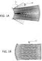
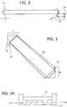
- the amplifying, laser-active part should be constructed in the form of a thin disc, so that its utilization becomes independent of the orientation of the receiver relative to the transmitter.
- the term "thin disc” in this context refers to the ratio of the thickness of the gain medium to its lateral dimension or dimensions, and not necessarily to the shape of it. Although a circular disc is most commonly used, the disk may be of other shapes, such as a rectangle or an oval or a triangle.
- Other terms used in the literature to describe thin gain media include, the terms active mirror, semiconductor thin disc, VECSEL and possibly other terms as well, and all are intended to be covered by the generic term "thin disc” used herein.
- the gain medium may be adapted to emit a laser beam essentially parallel to a laser beam incident upon it.
- the optical thickness profile across the width of the gain medium when the laser beam is traversing it may be such that the laser beam emerges from the gain medium in a direction essentially parallel to the direction in which the laser beam impinges on the gain medium.
- the optical thickness profile across the width of the gain medium may be controlled by means of a temperature profile generated across the width.
- the system may further comprise an additional optical element adapted to compensate for the change in the optical thickness profile of the gain medium arising from the lasing.
- a wireless power receiver for receiving a beam of optical power comprising:
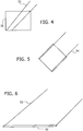
- Certain measures have to be taken to allow lasing operation over a wide range of positions and angular orientations of the receiver R for a given position of the transmitter, T. These measures are generally directed at providing a maximum field of view for the transmitter, where the field of view is understood to be the angular extent of the directions to which the transmitter can transmit to a receiver at any given time.
- Fig. 6 illustrates a solution enabled by use of a thin disc of lasing material 50.
- the good beam overlap over a wide field of view is also advantageous in that it ensures that most of the lasing medium volume is involved with generating the main beam being transmitted, such that little or none of it may contribute to lasing in a different direction.
- the thin disc of lasing material does not necessarily have to be disc shaped, i.e. round, but can be any shape, having its thickness between the surfaces of impingement of the laser beam substantially less than its lateral dimension.
- Such a thin disc of gain material is also known as an active mirror.
- a VECSEL (Vertical External Cavity Surface Emitting Laser) diode, also known as a semiconductor thin disc can also be used to provide such an advantageous overlap.
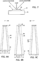
- FIGs. 8A to 8C illustrate schematically the laser cavity with the receiver 80 incorporating the thermal lensing element 81 mounted on the back mirror (or output coupler) of the cavity, and the gain medium 82 mounted within the transmitter unit 83.
- intra-cavity power For any choice of parameters it is possible to calculate the intra-cavity power using the above formula as well as Rayleigh's formula. However if a material with high dn/dT/K is chosen, the choice of intra-cavity power is more flexible.
- the minimal radius of the thermal mirror can be calculated.
- thermal focusing elements instead of a single one.
- Typical operation of the system from the start-up procedure may be illustrated in the exemplary flow chart of Fig. 10 , though it is to be understood that other possible schemes may equally well be used.
- the type of channel used to convey the information is shown by the form of the lines connecting the various steps.
- Electronic control signals transmitted most conveniently over hard wiring are shown as continuous lines.
- Control signals advantageously transmitted by RF or wireless are shown as faint dotted lines.
- Information determined by the content of the lasing beam is shown transferred by heavy dotted lines. It is to be understood, though, that other control in formation transfer schemes are also possible.
- the ordinate is the beam radius in microns
- the abscissa is the focusing power of the thermal lens in diopters (1 / m). Both curves assume that there is no thermal lensing at the transmitter.
- the top curve 130 shows the radius of the beam on the thermal lens in the receiver as a function of its focusing power
- the bottom curve 132 shows a radius of the beam on the gain medium as a function of the thermal lens focusing power.
- the beam spot size on thermal lens in the receiver is always larger than that on the gain medium in the transmitter.
- the focal length of the thermal lens the smaller the spot size on the gain media, and conversely for the spot size on the thermal lens.
- the dioptric power of the thermal lens must be kept somewhat below 2 / d. This means that it will vary considerably, if it is desired to operate with distances between T and R which may vary, for instance, between 1 m and 4 m. For large distances (large d), the beam radius at the receiver R becomes larger.
- the minimum beam radius at R is set by the maximum possible mode radius at the transmitter T, which is essentially given by the radius of the pumped spot of the active mirror, and by the corresponding beam divergence over the given range.
- w R is doubled, for example, the dissipated power has to be increased by a factor of 16 to achieve a given dioptric power.
- a doubling of w R corresponds approximately to doubling the distance d and thus to a reduction of the required dioptric power by a factor of 2. Nevertheless approximately 8 times the dissipated power is needed for twice the distance d, if the beam is always diffraction-limited.
- Eq. (1) also shows how it is possible to obtain a thermal lens mirror which has a sufficiently high dioptric power while absorbing only a moderate power: such lenders showed use a medium with high ⁇ n / ⁇ T , low thermal conductivity, and sufficient thickness, as previously explained the detailed description section of this application. Some further improvement is possible by having a somewhat reduced thermal conductivity for the substrate, but still high enough to ensure an essentially one-dimensional heat flow.
Claims (18)
- Freiraum-Lasersystem zum Erzeugen eines Laserstrahls, wobei das System umfasst:eine Energieübertragungseinheit (T), umfassend einen ersten Retroreflektor (12) und mit einem winkelförmigen Sichtfeld;mindestens eine Energieempfängereinheit (R), umfassend einen zweiten Retroreflektor (111), und relativ zur Energieübertragungseinheit entfernt positioniert;ein zwischen dem ersten und dem zweiten Retroreflektor, in der Nähe zum ersten Retroreflektor der Energieübertragungseinheit angeordnetes Verstärkungsmedium (13); und ein Element (16) zum Extrahieren von Energie aus dem Strahl, dadurch gekennzeichnet, dass das System ferner mindestens ein adaptives optisches Element (18) umfasst, das zwischen dem zweiten Retroreflektor (111) und dem Verstärkungsmedium (13) positioniert ist, wobei das adaptive optische Element (18) ein automatisch einstellbares Fokussierelement umfasst, wobei das adaptive optische Element (18) konfiguriert ist, um stabile Resonatorzustände zwischen dem ersten (12) und dem zweiten (111) Retroreflektor beizubehalten, indem es Änderungen in der Resonatorkonfiguration ausgleicht, die aus Bewegung der Energieempfängereinheit (R) entstehen.
- Freiraum-Lasersystem nach Anspruch 1, wobei das Gesichtsfeld mindestens ± 5 Grad beträgt.
- Freiraum-Lasersystem nach einem der vorstehenden Ansprüche, wobei das Verstärkungsmedium (13, 50) eine Dicke zwischen den Oberflächen, zwischen denen der Strahl durchläuft, aufweist, die im Wesentlichen kleiner als seine seitlichen Abmessungen ist.
- Freiraum-Lasersystem nach einem der vorstehenden Ansprüche, wobei das Verstärkungsmedium (13, 50) auf mindestens einer seiner Oberflächen eine Anti-Reflektions-Beschichtung aufweist, die angepasst ist, um Reflektion von der mindestens einen Oberfläche zu reduzieren, so dass das Lasern beibehalten wird, wenn der Strahl über im Wesentlichen jeden Teil des gesamten Gesichtsfelds ausgerichtet ist.
- Freiraum-Lasersystem nach Anspruch 4, wobei das mindestens eine adaptive optische Element (18) so ist, dass es den Durchmesser des auf das Verstärkungsmediums auftreffenden Laserstrahls verringert und dadurch die Überlappung zwischen dem Laserstrahl und dem Verstärkungsmedium erhöht.
- Freiraum-Lasersystem nach Anspruch 4 oder 5, wobei mindestens eines des mindestens einen adaptiven optischen Elements (18) und des Verstärkungsmediums (13, 50) ein solches Niveau an Doppelbrechung aufweist, dass die Erzeugung störender doppeltgebrochener Strahlen verringert wird.
- Freiraum-Lasersystem nach Anspruch 4 oder 5, wobei das mindestens eine adaptive optische Element (18) eines der Folgenden umfasst: eine thermische Linse;
eine entsprechend einem angelegten Steuersignal mechanisch verformbare Linse; einen entsprechend einem angelegten Steuersignal verformbaren Spiegel; ein pixeliertes Flüssigkristallarray, das so angeordnet ist, dass die Phasenverschiebung von eine Region des Elements durchlaufendem Licht entsprechend einem Steuersignal geändert werden kann, das auf mindestens ein an die Region angrenzendes Pixel angelegt wird. - Freiraum-Lasersystem nach Anspruch 7, wobei das angelegte Steuersignal (132) auf eine Charakteristik des Laserstrahls des Lasersystems bezogen ist.
- Freiraum-Lasersystem nach Anspruch 4, wobei die optische Form des mindestens einen adaptiven optischen Elements durch Feedback (131, 132, 127) von einer Charakteristik des Strahls bestimmt wird.
- Freiraum-Lasersystem nach Anspruch 9, wobei die Charakteristik vom Ausgabeenergieniveau des Laserstrahls (131) abgeleitet wird.
- Freiraum-Lasersystem nach Anspruch 5, wobei die Überlappung durch Einstellen der Fokussierleistung des mindestens einen adaptiven optischen Elements (18) maximiert wird, so dass der Laserstrahl infolge der Einstellung der Fokussierleistung keine zusätzliche Winkelverschiebung erfährt.
- Freiraum-Lasersystem nach einem der vorstehenden Ansprüche, wobei das optische Dickenprofil über die Breite des Verstärkungsmediums, wenn der Laserstrahl es durchläuft, so ist, dass der Laserstrahl in einer Richtung aus dem Verstärkungsmedium austritt, die im Wesentlichen parallel zu der Richtung ist, in der der Laserstrahl auf das Verstärkungsmedium auftritt, wobei das System ferner ein zusätzliches optisches Element umfasst, das angepasst ist, um die Änderung des optischen Dickenprofils des Verstärkungsmediums, die durch das Lasern entsteht, auszugleichen.
- Freiraum-Lasersystem nach einem der vorstehenden Ansprüche, wobei die seitliche Abmessung des Verstärkungsmediums so ausgewählt ist, dass die Rayleigh-Länge des Laserstrahls mindestens 2 % des Abstands zwischen der Übertragungseinheit und der Empfängereinheit beträgt.
- Freiraum-Lasersystem nach einem der vorstehenden Ansprüche, ferner umfassend einen optischen Detektor (112), der so angeordnet ist, dass er Objekte im Strahlweg detektiert.
- Freiraum-Lasersystem nach Anspruch 14, wobei die Objekte optisch durch Kontrollieren auf Änderungen in einer der Strahlleistung und der Übertragung eines Sondenlichtstrahls zwischen der Übertragungseinheit und der Empfängereinheit detektiert wird.
- Freiraum-Lasersystem nach einem der vorstehenden Ansprüche, wobei die Empfängereinheit ferner einen Funkdaten-Sender/Empfänger (116) zum Übermitteln und Empfangen von Signalen zu bzw. von der Übertragungseinheit umfasst, wobei der Sender/Empfänger das adaptive optische Element mittels einer empfangenen Signalanweisung initiiert.
- Freiraum-Lasersystem nach einem der vorstehenden Ansprüche, wobei das mindestens eine adaptive optische Element (18) ein automatisches Fokussierelement zum Modifizieren der Eigenschaften des Lasersystems ist, so dass die stabilen Resonatorzustände erhalten werden.
- Freiraum-Lasersystem nach einem der vorstehenden Ansprüche, wobei die Änderung der Resonatorkonfiguration aus Änderungen des Abstands zwischen, oder der wechselseitigen Ausrichtung der, Energieübertragungseinheit (T) und der Energieempfängereinheit (R) entsteht.
Priority Applications (1)
| Application Number | Priority Date | Filing Date | Title |
|---|---|---|---|
| EP19190568.6A EP3633824A1 (de) | 2008-01-03 | 2009-01-04 | Drahtloser laserleistungssender |
Applications Claiming Priority (2)
| Application Number | Priority Date | Filing Date | Title |
|---|---|---|---|
| US625508P | 2008-01-03 | 2008-01-03 | |
| PCT/IL2009/000010 WO2009083990A2 (en) | 2008-01-03 | 2009-01-04 | Wireless laser power transmitter |
Related Child Applications (2)
| Application Number | Title | Priority Date | Filing Date |
|---|---|---|---|
| EP19190568.6A Division EP3633824A1 (de) | 2008-01-03 | 2009-01-04 | Drahtloser laserleistungssender |
| EP18212670.6 Division-Into | 2008-01-03 | 2018-12-14 |
Publications (3)
| Publication Number | Publication Date |
|---|---|
| EP2235802A2 EP2235802A2 (de) | 2010-10-06 |
| EP2235802A4 EP2235802A4 (de) | 2015-12-30 |
| EP2235802B1 true EP2235802B1 (de) | 2019-03-06 |
Family
ID=40824822
Family Applications (2)
| Application Number | Title | Priority Date | Filing Date |
|---|---|---|---|
| EP09700130.9A Active EP2235802B1 (de) | 2008-01-03 | 2009-01-04 | Drahtloser laserleistungssender |
| EP19190568.6A Pending EP3633824A1 (de) | 2008-01-03 | 2009-01-04 | Drahtloser laserleistungssender |
Family Applications After (1)
| Application Number | Title | Priority Date | Filing Date |
|---|---|---|---|
| EP19190568.6A Pending EP3633824A1 (de) | 2008-01-03 | 2009-01-04 | Drahtloser laserleistungssender |
Country Status (4)
| Country | Link |
|---|---|
| US (4) | US8525097B2 (de) |
| EP (2) | EP2235802B1 (de) |
| CA (1) | CA2750244C (de) |
| WO (1) | WO2009083990A2 (de) |
Cited By (1)
| Publication number | Priority date | Publication date | Assignee | Title |
|---|---|---|---|---|
| RU2713561C1 (ru) * | 2019-05-28 | 2020-02-05 | Федеральное государственное бюджетное научное учреждение "Федеральный исследовательский центр Институт прикладной физики Российской академии наук" (ИПФ РАН) | Дисковый лазерный неустойчивый резонатор для обеспечения выходного лазерного сигнала с близким к дифракционному качеством пучка |
Families Citing this family (45)
| Publication number | Priority date | Publication date | Assignee | Title |
|---|---|---|---|---|
| US8525097B2 (en) * | 2008-01-03 | 2013-09-03 | Wi-Charge Ltd. | Wireless laser system for power transmission utilizing a gain medium between retroreflectors |
| DE102009054869B4 (de) * | 2009-04-09 | 2022-02-17 | Carl Zeiss Smt Gmbh | Spiegel zur Führung eines Strahlungsbündels, Vorrichtungen mit einem derartigen Spiegel sowie Verfahren zur Herstellung mikro- oder nanostrukturierter Bauelemente |
| DE102010061950A1 (de) * | 2010-11-25 | 2012-05-31 | Carl Zeiss Smt Gmbh | Verfahren sowie Anordnung zum Bestimmen des Erwärmungszustandes eines Spiegels in einem optischen System |
| EP2719097B3 (de) * | 2011-06-13 | 2023-06-07 | Wi-Charge Ltd. | Räumlich verteilter laserresonator |
| US9553959B2 (en) | 2011-12-29 | 2017-01-24 | Elwha Llc | Customized hardware selection for a mobile phone |
| US8391934B1 (en) | 2011-12-29 | 2013-03-05 | Elwha Llc | Customized hardware selection for a mobile phone |
| KR101517272B1 (ko) * | 2012-04-30 | 2015-05-04 | 한양대학교 산학협력단 | 비접촉 에너지 수신 장치 및 그 제어 방법 |
| CN103683523B (zh) * | 2012-09-07 | 2018-04-13 | 捷通国际有限公司 | 用于双向无线功率传输的系统和方法 |
| DE102012023719B4 (de) | 2012-12-05 | 2023-05-25 | Airbus Defence and Space GmbH | Drahtlose Fernenergieversorgung für unbemannte Fluggeräte |
| EP3008541A4 (de) | 2013-06-14 | 2017-02-22 | Intel Corporation | Verfahren und vorrichtung zur stromversorgung von vorrichtungen |
| US9991753B2 (en) * | 2014-06-11 | 2018-06-05 | Enovate Medical Llc | Variable wireless transfer |
| JP5941112B2 (ja) * | 2014-09-30 | 2016-06-29 | ファナック株式会社 | ビーム品質を向上させるレーザ発振器 |
| US10359035B2 (en) * | 2014-10-15 | 2019-07-23 | Ge Aviation Systems Llc | Air agitator assemblies |
| US10028408B2 (en) | 2014-10-15 | 2018-07-17 | Ge Aviation Systems Llc | Air agitator assemblies |
| CN107005262A (zh) * | 2014-10-22 | 2017-08-01 | 埃尔瓦有限公司 | 移动电话的定制硬件选择 |
| EP3254384B1 (de) | 2015-02-02 | 2021-11-24 | Wi-Charge Ltd. | Verteilter optischer resonator mit dünner empfängereinheit |
| US20160359330A1 (en) * | 2015-06-06 | 2016-12-08 | Ruxiang Jin | Systems and Methods for Dynamic Energy Distribution |
| US9941965B2 (en) * | 2015-07-15 | 2018-04-10 | Flextronics Ap, Llc | Laser and optical charging and communications device and method of use |
| US9312701B1 (en) * | 2015-07-16 | 2016-04-12 | Wi-Charge Ltd | System for optical wireless power supply |
| CN114977541A (zh) * | 2015-08-24 | 2022-08-30 | Wi-电荷有限公司 | 无线功率分配系统 |
| US10264650B2 (en) | 2015-08-31 | 2019-04-16 | The Boeing Company | System and method for contactless energy transfer to a moving platform |
| EP3430738B1 (de) * | 2016-03-14 | 2021-10-13 | Wi-Charge Ltd. | System zur optischen drahtlosen energieversorgung |
| CN115313694A (zh) * | 2016-04-11 | 2022-11-08 | Wi-电荷有限公司 | 光学无线供电系统 |
| WO2017205549A2 (en) * | 2016-05-24 | 2017-11-30 | California Institute Of Technology | Laser wireless power transfer system with active and passive safety measures |
| KR102614490B1 (ko) | 2016-12-12 | 2023-12-15 | 엘지전자 주식회사 | 무선전력 전송장치 및 방법 |
| CA3048535C (en) * | 2017-01-06 | 2023-08-08 | Macquarie University | Single longitudinal mode ring raman laser |
| KR102652071B1 (ko) | 2017-05-15 | 2024-03-27 | 위-차지 리미티드. | 광학 무선 전력 공급을 위한 유연한 관리 시스템 |
| CN107566037A (zh) * | 2017-08-01 | 2018-01-09 | 杭州电子科技大学 | 双工逆向调制mrr自由空间激光通信fso系统 |
| EP4351026A2 (de) | 2017-09-28 | 2024-04-10 | Wi-Charge Ltd. | Ausfallsichere optische drahtlose stromversorgung |
| EP3701646A2 (de) * | 2017-10-23 | 2020-09-02 | Felicelli, Antoine | Energieübertragungsvorrichtung, energiegewinnungsvorrichtung und leistungsabstrahlungssystem |
| WO2019135226A1 (en) * | 2018-01-02 | 2019-07-11 | Wi-Charge Ltd | Multiple beam wireless power transmission system |
| JP7208654B2 (ja) | 2018-02-23 | 2023-01-19 | ファイオン・テクノロジーズ・コーポレイション | 安全でセキュアな自由空間電力伝送及びデータ伝送の方法 |
| WO2019224827A1 (en) | 2018-05-23 | 2019-11-28 | Wi-Charge Ltd | Wireless power system having identifiable receivers |
| US10971818B2 (en) | 2018-09-04 | 2021-04-06 | Elwha Llc | Open cavity system for directed amplification of radio frequency signals |
| US10992325B2 (en) | 2018-09-04 | 2021-04-27 | Elwha Llc | Open cavity system for directed amplification of acoustic signals |
| CN111446345A (zh) | 2019-01-16 | 2020-07-24 | 隆达电子股份有限公司 | 发光元件的封装结构 |
| US20240097498A9 (en) * | 2019-04-19 | 2024-03-21 | Guru, Inc. | Adaptive roaming and articulating generating unit for wireless power transfer |
| KR102168373B1 (ko) * | 2019-05-24 | 2020-10-22 | 세종대학교산학협력단 | 무선 광 충전 시스템 및 그 충전 방법 |
| KR102217535B1 (ko) | 2019-07-05 | 2021-02-18 | 엘지전자 주식회사 | 무선 전력 송수신 장치 및 이를 포함하는 디스플레이 시스템 |
| DE102019008569B4 (de) | 2019-12-11 | 2024-02-01 | Diehl Aerospace Gmbh | Kabineninnenanordnung mit einer Energieübertragungsanordnung für ein Flugzeug sowie Flugzeug mit der Kabineninnenanordnung |
| DE102020107778A1 (de) | 2020-03-20 | 2021-09-23 | Enocean Gmbh | System und Verfahren zur drahtlosen Übertragung von Energie |
| US11196487B1 (en) | 2020-07-31 | 2021-12-07 | Scidatek Inc. | Free-space communication and wireless power transfer system and method of using same |
| US11821251B2 (en) | 2020-09-17 | 2023-11-21 | Gmi Holdings, Inc. | Laser powered door operating system |
| KR102342306B1 (ko) * | 2020-11-30 | 2021-12-22 | 한화시스템 주식회사 | 충전방법 및 충전장치 |
| IL287976A (en) * | 2021-11-09 | 2023-06-01 | Wi Charge Ltd | Scanning mirror for laser power transmission system |
Family Cites Families (73)
| Publication number | Priority date | Publication date | Assignee | Title |
|---|---|---|---|---|
| US514168A (en) | 1894-02-06 | Nikola tesla | ||
| US593138A (en) | 1897-11-02 | Nikola Tesla | Electrical Transformer | |
| US645576A (en) | 1897-09-02 | 1900-03-20 | Nikola Tesla | System of transmission of electrical energy. |
| US685955A (en) | 1899-06-24 | 1901-11-05 | Nikola Tesla | Apparatus for utilizing effects transmitted from a distance to a receiving device through natural media. |
| US685954A (en) | 1899-08-01 | 1901-11-05 | Nikola Tesla | Method of utilizing effects transmitted through natural media. |
| US685956A (en) | 1899-08-01 | 1901-11-05 | Nikola Tesla | Apparatus for utilizing effects transmitted through natural media. |
| US787412A (en) | 1900-05-16 | 1905-04-18 | Nikola Tesla | Art of transmitting electrical energy through the natural mediums. |
| US685957A (en) | 1901-03-21 | 1901-11-05 | Nikola Tesla | Apparatus for the utilization of radiant energy. |
| US685593A (en) | 1901-04-19 | 1901-10-29 | Frank A Franklin | Process of reclaiming pulp. |
| US1119732A (en) | 1907-05-04 | 1914-12-01 | Nikola Tesla | Apparatus for transmitting electrical energy. |
| US3215842A (en) | 1963-04-18 | 1965-11-02 | Numa E Thomas | Optical communications system |
| US3566126A (en) | 1967-11-29 | 1971-02-23 | Sylvania Electric Prod | Acquisition and tracking laser communication system |
| US4209689A (en) * | 1969-06-04 | 1980-06-24 | Hughes Aircraft Company | Laser secure communications system |
| DE2453077B2 (de) | 1974-11-08 | 1976-09-02 | Precitronic Gesellschaft für Feinmechanik und Electronic mbH, 2000 Hamburg | Empfangs-sendeeinrichtung fuer die informationsuebermittlung mittels gebuendelter, modulierter lichtstrahlen |
| US4131791A (en) | 1975-12-08 | 1978-12-26 | General Electric Company | Search and locate system |
| US4114151A (en) | 1976-09-14 | 1978-09-12 | Alfa-Laval Company Limited | Passive transponder apparatus for use in an interrogator-responder system |
| US4490823A (en) * | 1983-03-07 | 1984-12-25 | Northrop Corporation | Injection-locked unstable laser |
| US4866781A (en) * | 1983-04-01 | 1989-09-12 | Honeywell Inc. | Method and means of identifying objects with retro-reflected light |
| US4872743A (en) | 1983-04-18 | 1989-10-10 | Canon Kabushiki Kaisha | Varifocal optical element |
| DE3328335A1 (de) | 1983-08-05 | 1985-02-14 | Messerschmitt-Bölkow-Blohm GmbH, 8012 Ottobrunn | Datenfernueberwachungssystem |
| CH663287A5 (de) | 1984-05-03 | 1987-11-30 | Landis & Gyr Ag | Einrichtung mit kontaktloser informationsuebertragung zwischen einem identifikator und einem identifikanden. |
| US4777660A (en) | 1984-11-06 | 1988-10-11 | Optelecom Incorporated | Retroreflective optical communication system |
| US4983021A (en) | 1988-08-10 | 1991-01-08 | Fergason James L | Modulated retroreflector system |
| ES2072271T3 (es) | 1989-03-17 | 1995-07-16 | Siemens Ag | Componente autarquico accionado con fotones. |
| JP2899013B2 (ja) | 1989-07-03 | 1999-06-02 | 俊弘 津村 | 移動体に対する位置情報伝達システム |
| US5648901A (en) * | 1990-02-05 | 1997-07-15 | Caterpillar Inc. | System and method for generating paths in an autonomous vehicle |
| US5048051A (en) | 1990-03-02 | 1991-09-10 | Massachusetts Institute Of Technology | Optically-stabilized plano-plano optical resonators |
| US5193201A (en) | 1990-04-23 | 1993-03-09 | Tymes Laroy | System for converting a received modulated light into both power for the system and image data displayed by the system |
| US5121242A (en) | 1991-02-04 | 1992-06-09 | Martin Marietta Corporation | Retro-reflective optical transceiver |
| US5132980A (en) * | 1991-02-13 | 1992-07-21 | Coherent, Inc. | Method and device for preconditioning a laser having a solid state gain medium |
| US5251221A (en) | 1992-08-10 | 1993-10-05 | Hughes Aircraft Company | Self aligning intracavity Raman laser |
| US5553088A (en) | 1993-07-02 | 1996-09-03 | Deutsche Forschungsanstalt Fuer Luft- Und Raumfahrt E.V. | Laser amplifying system |
| US5577060A (en) * | 1994-02-04 | 1996-11-19 | Spectra Physics Lasers, Inc. | Diode pumped laser using crystals with strong thermal focussing |
| US5386427A (en) | 1994-02-10 | 1995-01-31 | Massachusetts Institute Of Technology | Thermally controlled lenses for lasers |
| US5461637A (en) * | 1994-03-16 | 1995-10-24 | Micracor, Inc. | High brightness, vertical cavity semiconductor lasers |
| US5528409A (en) | 1994-10-13 | 1996-06-18 | Nt International, Inc. | Fiber-optic interface system |
| DE4444636A1 (de) * | 1994-12-15 | 1996-06-20 | Sepp Gunther | Waffensystem für einen Blendlaser |
| DE19510780A1 (de) | 1995-03-24 | 1996-09-26 | Stasys Malkevicius | Drahtloses Elektroenergie-Übertragungssystem |
| US5819164A (en) | 1996-01-29 | 1998-10-06 | The United States Of America As Represented By The Secretary Of The Army | Modulated retroreflection system for secure communication and identification |
| CA2279934A1 (en) | 1997-02-11 | 1998-08-13 | Scientific Generics Limited | Signalling system |
| US7068991B2 (en) * | 1997-05-09 | 2006-06-27 | Parise Ronald J | Remote power recharge for electronic equipment |
| US6381055B1 (en) * | 1998-04-16 | 2002-04-30 | At&T Corp. | Transceiver positioning in free-space optical networks |
| GB9810039D0 (en) | 1998-05-11 | 1998-07-08 | Isis Innovation | Communications device |
| FR2781613B1 (fr) | 1998-07-27 | 2000-10-06 | Photonetics | Laser en espace libre avec sortie fibre autoalignee |
| US6493123B1 (en) | 1999-10-27 | 2002-12-10 | Northrop Grumman Corporation | Modulated-retroreflector based optical identification system |
| AU2529201A (en) | 1999-12-07 | 2001-06-18 | Moshe Klotz | Off-axis light-detector assembly |
| US6388803B1 (en) | 2000-03-02 | 2002-05-14 | Agere Systems Guardian Corp. | Article comprising a broad band optical amplifier |
| US7224905B2 (en) | 2000-04-07 | 2007-05-29 | The Regents Of The University Of California | Remotely-interrogated high data rate free space laser communications link |
| DE10085455T1 (de) | 2000-04-14 | 2003-02-27 | Fujitsu Ltd | Optische Positionsdetektiervorrichtung und Aufzeichnungsmedium |
| US6407535B1 (en) | 2000-09-08 | 2002-06-18 | The Regents Of The University Of California | System for beaming power from earth to a high altitude platform |
| WO2002025358A2 (en) * | 2000-09-22 | 2002-03-28 | Movaz Networks, Inc. | Variable transmission multi-channel optical switch |
| WO2002103935A1 (en) | 2001-06-15 | 2002-12-27 | Al-Chalabi Salah A | Optical communication device and system |
| FI111670B (fi) * | 2001-10-24 | 2003-08-29 | Patria Ailon Oy | Langaton tehonsiirto |
| US7489865B2 (en) | 2002-02-01 | 2009-02-10 | Cubic Corporation | Integrated optical communication and range finding system and applications thereof |
| US20030169784A1 (en) * | 2002-03-08 | 2003-09-11 | Sutter Dirk H. | Method and device to avoid optical damage of an intracavity optic |
| US6906495B2 (en) | 2002-05-13 | 2005-06-14 | Splashpower Limited | Contact-less power transfer |
| US6979088B2 (en) | 2002-06-11 | 2005-12-27 | The United States Of America As Represented By The Secretary Of The Navy | Multipass optical retroreflector and method of using |
| ITMI20022211A1 (it) | 2002-10-18 | 2004-04-19 | Cit Alcatel | Regolazione della potenza irradiata su un telescopio di |
| US6798716B1 (en) | 2003-06-19 | 2004-09-28 | Bc Systems, Inc. | System and method for wireless electrical power transmission |
| US7693426B2 (en) | 2003-12-18 | 2010-04-06 | Hewlett-Packard Development Company, L.P. | Laser-based communications with a remote information source |
| DE102004008681A1 (de) * | 2004-02-21 | 2005-09-08 | Eads Space Transportation Gmbh | Verfahren zur Energieübertragung mittels kohärenter elektromagnetischer Strahlung |
| US7360703B2 (en) | 2004-09-23 | 2008-04-22 | Ut-Battelle, Llc | Laser scanning system for object monitoring |
| JP2006156782A (ja) * | 2004-11-30 | 2006-06-15 | National Institute Of Information & Communication Technology | レーザ発振器 |
| US20070019693A1 (en) * | 2005-03-07 | 2007-01-25 | Graham David S | Wireless power beaming to common electronic devices |
| US7609249B2 (en) | 2005-04-21 | 2009-10-27 | Avago Technologies Ecbu Ip (Singapore) Pte. Ltd. | Position determination utilizing a cordless device |
| US7603041B2 (en) | 2005-06-09 | 2009-10-13 | Cubic Corporation | Temperature compensated dynamic optical tag modulator system and method |
| EP1929678B1 (de) | 2005-09-27 | 2018-03-14 | Wi-Charge Ltd. | Gerichteter lichtsender und -empfänger |
| US20080084596A1 (en) | 2006-10-06 | 2008-04-10 | Powerbeam, Inc. | Active Mirror for Power Beaming |
| US7912369B2 (en) | 2006-10-09 | 2011-03-22 | Verizon Services Corp. | Optical signal shutoff mechanism and associated system |
| EP2089942A4 (de) | 2006-11-21 | 2011-04-27 | Powerbeam Inc | Optisches leistungs-beaming zu elektrisch gestromten anordnungen |
| JP4098341B1 (ja) | 2006-12-28 | 2008-06-11 | 北陽電機株式会社 | 走査式測距装置の光学窓汚れ検出装置 |
| US8213804B2 (en) * | 2007-06-05 | 2012-07-03 | Intel Corporation | Semiconductor optical amplifier for an external cavity diode laser |
| US8525097B2 (en) * | 2008-01-03 | 2013-09-03 | Wi-Charge Ltd. | Wireless laser system for power transmission utilizing a gain medium between retroreflectors |
-
2009
- 2009-01-04 US US12/811,382 patent/US8525097B2/en active Active
- 2009-01-04 WO PCT/IL2009/000010 patent/WO2009083990A2/en active Application Filing
- 2009-01-04 CA CA2750244A patent/CA2750244C/en active Active
- 2009-01-04 EP EP09700130.9A patent/EP2235802B1/de active Active
- 2009-01-04 EP EP19190568.6A patent/EP3633824A1/de active Pending
-
2013
- 2013-09-02 US US14/016,151 patent/US9312660B2/en active Active
-
2016
- 2016-04-11 US US15/095,373 patent/US9653949B2/en active Active
-
2017
- 2017-05-10 US US15/591,151 patent/US10404103B2/en active Active
Non-Patent Citations (1)
| Title |
|---|
| None * |
Cited By (1)
| Publication number | Priority date | Publication date | Assignee | Title |
|---|---|---|---|---|
| RU2713561C1 (ru) * | 2019-05-28 | 2020-02-05 | Федеральное государственное бюджетное научное учреждение "Федеральный исследовательский центр Институт прикладной физики Российской академии наук" (ИПФ РАН) | Дисковый лазерный неустойчивый резонатор для обеспечения выходного лазерного сигнала с близким к дифракционному качеством пучка |
Also Published As
| Publication number | Publication date |
|---|---|
| WO2009083990A3 (en) | 2010-03-11 |
| US8525097B2 (en) | 2013-09-03 |
| US20140092929A1 (en) | 2014-04-03 |
| CA2750244C (en) | 2017-03-07 |
| EP2235802A4 (de) | 2015-12-30 |
| US9653949B2 (en) | 2017-05-16 |
| CA2750244A1 (en) | 2009-07-09 |
| WO2009083990A2 (en) | 2009-07-09 |
| US20160329754A1 (en) | 2016-11-10 |
| US10404103B2 (en) | 2019-09-03 |
| US20100320362A1 (en) | 2010-12-23 |
| US20170373543A1 (en) | 2017-12-28 |
| EP2235802A2 (de) | 2010-10-06 |
| EP3633824A1 (de) | 2020-04-08 |
| US9312660B2 (en) | 2016-04-12 |
Similar Documents
| Publication | Publication Date | Title |
|---|---|---|
| US10404103B2 (en) | Wireless laser system for power transmission with gain medium control based on beam power or shape | |
| US9905988B2 (en) | Spatially distributed laser resonator | |
| KR101324265B1 (ko) | 레이저 장치 | |
| US9705606B2 (en) | Directional light transmitter and receiver | |
| CN103182604B (zh) | 激光复合焊接方法与系统 | |
| JP2019516334A (ja) | 光無線給電システム | |
| JP2019526924A (ja) | 周波数二倍化レーザ及び高調波レーザを生成する方法 | |
| CN108988117B (zh) | 一种基于偏振合成激光增益的激光放大器 | |
| US20200251874A1 (en) | Continuous wave end-pumped laser | |
| JPS62500135A (ja) | 臨界角回転プリズムqスイッチ | |
| US20050129083A1 (en) | Optical bench for diode-pumped solid state lasers in field applications | |
| CN113300491B (zh) | 一种可多点接入的激光无线能量传输系统 | |
| US11482828B2 (en) | Passively Q-switched laser and laser system for ranging applications | |
| Pavel et al. | Stable resonators for fundamental mode operation | |
| Bigotta et al. | Latest developments on the Er3+: YAG solid state heat-capacity laser | |
| CN113241575A (zh) | 一种人眼安全激光器结构 |
Legal Events
| Date | Code | Title | Description |
|---|---|---|---|
| PUAI | Public reference made under article 153(3) epc to a published international application that has entered the european phase |
Free format text: ORIGINAL CODE: 0009012 |
|
| 17P | Request for examination filed |
Effective date: 20100802 |
|
| AK | Designated contracting states |
Kind code of ref document: A2 Designated state(s): AT BE BG CH CY CZ DE DK EE ES FI FR GB GR HR HU IE IS IT LI LT LU LV MC MK MT NL NO PL PT RO SE SI SK TR |
|
| AX | Request for extension of the european patent |
Extension state: AL BA RS |
|
| DAX | Request for extension of the european patent (deleted) | ||
| A4 | Supplementary search report drawn up and despatched |
Effective date: 20151127 |
|
| RIC1 | Information provided on ipc code assigned before grant |
Ipc: H01S 3/06 20060101ALI20151123BHEP Ipc: H04B 10/114 20130101ALI20151123BHEP Ipc: H01S 3/0973 20060101AFI20151123BHEP Ipc: H01S 5/183 20060101ALI20151123BHEP Ipc: H01S 3/0941 20060101ALI20151123BHEP Ipc: H01S 3/08 20060101ALI20151123BHEP Ipc: H04B 10/80 20130101ALI20151123BHEP Ipc: H01S 5/14 20060101ALI20151123BHEP Ipc: H01S 5/04 20060101ALI20151123BHEP Ipc: H01S 3/083 20060101ALI20151123BHEP Ipc: H01S 3/13 20060101ALI20151123BHEP |
|
| R17P | Request for examination filed (corrected) |
Effective date: 20100802 |
|
| GRAP | Despatch of communication of intention to grant a patent |
Free format text: ORIGINAL CODE: EPIDOSNIGR1 |
|
| STAA | Information on the status of an ep patent application or granted ep patent |
Free format text: STATUS: GRANT OF PATENT IS INTENDED |
|
| RIC1 | Information provided on ipc code assigned before grant |
Ipc: H01S 3/0941 20060101ALI20180801BHEP Ipc: H01S 3/00 20060101ALI20180801BHEP Ipc: H01S 3/08 20060101ALI20180801BHEP Ipc: H04B 10/80 20130101ALI20180801BHEP Ipc: H01S 5/183 20060101ALI20180801BHEP Ipc: H01S 5/04 20060101ALI20180801BHEP Ipc: H02J 50/30 20160101ALI20180801BHEP Ipc: H01S 3/083 20060101ALI20180801BHEP Ipc: H04B 1/04 20060101ALI20180801BHEP Ipc: H01S 5/14 20060101ALI20180801BHEP Ipc: H01S 3/13 20060101ALI20180801BHEP Ipc: H01S 3/06 20060101ALI20180801BHEP Ipc: H01S 3/0973 20060101AFI20180801BHEP Ipc: H04B 10/114 20130101ALI20180801BHEP |
|
| INTG | Intention to grant announced |
Effective date: 20180814 |
|
| GRAS | Grant fee paid |
Free format text: ORIGINAL CODE: EPIDOSNIGR3 |
|
| RAP1 | Party data changed (applicant data changed or rights of an application transferred) |
Owner name: WI-CHARGE LTD. |
|
| GRAA | (expected) grant |
Free format text: ORIGINAL CODE: 0009210 |
|
| STAA | Information on the status of an ep patent application or granted ep patent |
Free format text: STATUS: THE PATENT HAS BEEN GRANTED |
|
| RIC1 | Information provided on ipc code assigned before grant |
Ipc: H01S 5/14 20060101ALI20180801BHEP Ipc: H04B 10/114 20130101ALI20180801BHEP Ipc: H01S 3/0973 20060101AFI20180801BHEP Ipc: H01S 3/00 20060101ALI20180801BHEP Ipc: H01S 5/183 20060101ALI20180801BHEP Ipc: H04B 1/04 20060101ALI20180801BHEP Ipc: H01S 3/13 20060101ALI20180801BHEP Ipc: H04B 10/80 20130101ALI20180801BHEP Ipc: H01S 3/083 20060101ALI20180801BHEP Ipc: H01S 5/04 20060101ALI20180801BHEP Ipc: H01S 3/06 20060101ALI20180801BHEP Ipc: H02J 50/30 20160101ALI20180801BHEP Ipc: H01S 3/08 20060101ALI20180801BHEP Ipc: H01S 3/0941 20060101ALI20180801BHEP |
|
| AK | Designated contracting states |
Kind code of ref document: B1 Designated state(s): AT BE BG CH CY CZ DE DK EE ES FI FR GB GR HR HU IE IS IT LI LT LU LV MC MK MT NL NO PL PT RO SE SI SK TR |
|
| REG | Reference to a national code |
Ref country code: GB Ref legal event code: FG4D |
|
| REG | Reference to a national code |
Ref country code: CH Ref legal event code: EP Ref country code: AT Ref legal event code: REF Ref document number: 1105818 Country of ref document: AT Kind code of ref document: T Effective date: 20190315 |
|
| REG | Reference to a national code |
Ref country code: DE Ref legal event code: R096 Ref document number: 602009057303 Country of ref document: DE |
|
| REG | Reference to a national code |
Ref country code: IE Ref legal event code: FG4D |
|
| REG | Reference to a national code |
Ref country code: NL Ref legal event code: MP Effective date: 20190306 |
|
| REG | Reference to a national code |
Ref country code: LT Ref legal event code: MG4D |
|
| PG25 | Lapsed in a contracting state [announced via postgrant information from national office to epo] |
Ref country code: NO Free format text: LAPSE BECAUSE OF FAILURE TO SUBMIT A TRANSLATION OF THE DESCRIPTION OR TO PAY THE FEE WITHIN THE PRESCRIBED TIME-LIMIT Effective date: 20190606 Ref country code: LT Free format text: LAPSE BECAUSE OF FAILURE TO SUBMIT A TRANSLATION OF THE DESCRIPTION OR TO PAY THE FEE WITHIN THE PRESCRIBED TIME-LIMIT Effective date: 20190306 Ref country code: FI Free format text: LAPSE BECAUSE OF FAILURE TO SUBMIT A TRANSLATION OF THE DESCRIPTION OR TO PAY THE FEE WITHIN THE PRESCRIBED TIME-LIMIT Effective date: 20190306 Ref country code: SE Free format text: LAPSE BECAUSE OF FAILURE TO SUBMIT A TRANSLATION OF THE DESCRIPTION OR TO PAY THE FEE WITHIN THE PRESCRIBED TIME-LIMIT Effective date: 20190306 |
|
| PG25 | Lapsed in a contracting state [announced via postgrant information from national office to epo] |
Ref country code: BG Free format text: LAPSE BECAUSE OF FAILURE TO SUBMIT A TRANSLATION OF THE DESCRIPTION OR TO PAY THE FEE WITHIN THE PRESCRIBED TIME-LIMIT Effective date: 20190606 Ref country code: HR Free format text: LAPSE BECAUSE OF FAILURE TO SUBMIT A TRANSLATION OF THE DESCRIPTION OR TO PAY THE FEE WITHIN THE PRESCRIBED TIME-LIMIT Effective date: 20190306 Ref country code: GR Free format text: LAPSE BECAUSE OF FAILURE TO SUBMIT A TRANSLATION OF THE DESCRIPTION OR TO PAY THE FEE WITHIN THE PRESCRIBED TIME-LIMIT Effective date: 20190607 Ref country code: LV Free format text: LAPSE BECAUSE OF FAILURE TO SUBMIT A TRANSLATION OF THE DESCRIPTION OR TO PAY THE FEE WITHIN THE PRESCRIBED TIME-LIMIT Effective date: 20190306 Ref country code: NL Free format text: LAPSE BECAUSE OF FAILURE TO SUBMIT A TRANSLATION OF THE DESCRIPTION OR TO PAY THE FEE WITHIN THE PRESCRIBED TIME-LIMIT Effective date: 20190306 |
|
| REG | Reference to a national code |
Ref country code: AT Ref legal event code: MK05 Ref document number: 1105818 Country of ref document: AT Kind code of ref document: T Effective date: 20190306 |
|
| PG25 | Lapsed in a contracting state [announced via postgrant information from national office to epo] |
Ref country code: RO Free format text: LAPSE BECAUSE OF FAILURE TO SUBMIT A TRANSLATION OF THE DESCRIPTION OR TO PAY THE FEE WITHIN THE PRESCRIBED TIME-LIMIT Effective date: 20190306 Ref country code: SK Free format text: LAPSE BECAUSE OF FAILURE TO SUBMIT A TRANSLATION OF THE DESCRIPTION OR TO PAY THE FEE WITHIN THE PRESCRIBED TIME-LIMIT Effective date: 20190306 Ref country code: ES Free format text: LAPSE BECAUSE OF FAILURE TO SUBMIT A TRANSLATION OF THE DESCRIPTION OR TO PAY THE FEE WITHIN THE PRESCRIBED TIME-LIMIT Effective date: 20190306 Ref country code: CZ Free format text: LAPSE BECAUSE OF FAILURE TO SUBMIT A TRANSLATION OF THE DESCRIPTION OR TO PAY THE FEE WITHIN THE PRESCRIBED TIME-LIMIT Effective date: 20190306 Ref country code: EE Free format text: LAPSE BECAUSE OF FAILURE TO SUBMIT A TRANSLATION OF THE DESCRIPTION OR TO PAY THE FEE WITHIN THE PRESCRIBED TIME-LIMIT Effective date: 20190306 Ref country code: PT Free format text: LAPSE BECAUSE OF FAILURE TO SUBMIT A TRANSLATION OF THE DESCRIPTION OR TO PAY THE FEE WITHIN THE PRESCRIBED TIME-LIMIT Effective date: 20190706 |
|
| PG25 | Lapsed in a contracting state [announced via postgrant information from national office to epo] |
Ref country code: PL Free format text: LAPSE BECAUSE OF FAILURE TO SUBMIT A TRANSLATION OF THE DESCRIPTION OR TO PAY THE FEE WITHIN THE PRESCRIBED TIME-LIMIT Effective date: 20190306 |
|
| REG | Reference to a national code |
Ref country code: DE Ref legal event code: R097 Ref document number: 602009057303 Country of ref document: DE |
|
| PG25 | Lapsed in a contracting state [announced via postgrant information from national office to epo] |
Ref country code: AT Free format text: LAPSE BECAUSE OF FAILURE TO SUBMIT A TRANSLATION OF THE DESCRIPTION OR TO PAY THE FEE WITHIN THE PRESCRIBED TIME-LIMIT Effective date: 20190306 Ref country code: IS Free format text: LAPSE BECAUSE OF FAILURE TO SUBMIT A TRANSLATION OF THE DESCRIPTION OR TO PAY THE FEE WITHIN THE PRESCRIBED TIME-LIMIT Effective date: 20190706 |
|
| PLBE | No opposition filed within time limit |
Free format text: ORIGINAL CODE: 0009261 |
|
| STAA | Information on the status of an ep patent application or granted ep patent |
Free format text: STATUS: NO OPPOSITION FILED WITHIN TIME LIMIT |
|
| PG25 | Lapsed in a contracting state [announced via postgrant information from national office to epo] |
Ref country code: DK Free format text: LAPSE BECAUSE OF FAILURE TO SUBMIT A TRANSLATION OF THE DESCRIPTION OR TO PAY THE FEE WITHIN THE PRESCRIBED TIME-LIMIT Effective date: 20190306 |
|
| 26N | No opposition filed |
Effective date: 20191209 |
|
| PG25 | Lapsed in a contracting state [announced via postgrant information from national office to epo] |
Ref country code: SI Free format text: LAPSE BECAUSE OF FAILURE TO SUBMIT A TRANSLATION OF THE DESCRIPTION OR TO PAY THE FEE WITHIN THE PRESCRIBED TIME-LIMIT Effective date: 20190306 |
|
| PG25 | Lapsed in a contracting state [announced via postgrant information from national office to epo] |
Ref country code: TR Free format text: LAPSE BECAUSE OF FAILURE TO SUBMIT A TRANSLATION OF THE DESCRIPTION OR TO PAY THE FEE WITHIN THE PRESCRIBED TIME-LIMIT Effective date: 20190306 |
|
| PG25 | Lapsed in a contracting state [announced via postgrant information from national office to epo] |
Ref country code: MC Free format text: LAPSE BECAUSE OF FAILURE TO SUBMIT A TRANSLATION OF THE DESCRIPTION OR TO PAY THE FEE WITHIN THE PRESCRIBED TIME-LIMIT Effective date: 20190306 |
|
| REG | Reference to a national code |
Ref country code: CH Ref legal event code: PL |
|
| REG | Reference to a national code |
Ref country code: BE Ref legal event code: MM Effective date: 20200131 |
|
| PG25 | Lapsed in a contracting state [announced via postgrant information from national office to epo] |
Ref country code: LU Free format text: LAPSE BECAUSE OF NON-PAYMENT OF DUE FEES Effective date: 20200104 |
|
| PG25 | Lapsed in a contracting state [announced via postgrant information from national office to epo] |
Ref country code: LI Free format text: LAPSE BECAUSE OF NON-PAYMENT OF DUE FEES Effective date: 20200131 Ref country code: CH Free format text: LAPSE BECAUSE OF NON-PAYMENT OF DUE FEES Effective date: 20200131 Ref country code: BE Free format text: LAPSE BECAUSE OF NON-PAYMENT OF DUE FEES Effective date: 20200131 |
|
| PG25 | Lapsed in a contracting state [announced via postgrant information from national office to epo] |
Ref country code: MT Free format text: LAPSE BECAUSE OF FAILURE TO SUBMIT A TRANSLATION OF THE DESCRIPTION OR TO PAY THE FEE WITHIN THE PRESCRIBED TIME-LIMIT Effective date: 20190306 Ref country code: CY Free format text: LAPSE BECAUSE OF FAILURE TO SUBMIT A TRANSLATION OF THE DESCRIPTION OR TO PAY THE FEE WITHIN THE PRESCRIBED TIME-LIMIT Effective date: 20190306 |
|
| PG25 | Lapsed in a contracting state [announced via postgrant information from national office to epo] |
Ref country code: MK Free format text: LAPSE BECAUSE OF FAILURE TO SUBMIT A TRANSLATION OF THE DESCRIPTION OR TO PAY THE FEE WITHIN THE PRESCRIBED TIME-LIMIT Effective date: 20190306 |
|
| PGFP | Annual fee paid to national office [announced via postgrant information from national office to epo] |
Ref country code: IE Payment date: 20230126 Year of fee payment: 15 Ref country code: FR Payment date: 20230123 Year of fee payment: 15 |
|
| PGFP | Annual fee paid to national office [announced via postgrant information from national office to epo] |
Ref country code: IT Payment date: 20230127 Year of fee payment: 15 Ref country code: GB Payment date: 20230117 Year of fee payment: 15 Ref country code: DE Payment date: 20230131 Year of fee payment: 15 |