EP1929678B1 - Gerichteter lichtsender und -empfänger - Google Patents
Gerichteter lichtsender und -empfänger Download PDFInfo
- Publication number
- EP1929678B1 EP1929678B1 EP06796128.4A EP06796128A EP1929678B1 EP 1929678 B1 EP1929678 B1 EP 1929678B1 EP 06796128 A EP06796128 A EP 06796128A EP 1929678 B1 EP1929678 B1 EP 1929678B1
- Authority
- EP
- European Patent Office
- Prior art keywords
- receiver
- transmitting unit
- unit
- optical
- radiation
- Prior art date
- Legal status (The legal status is an assumption and is not a legal conclusion. Google has not performed a legal analysis and makes no representation as to the accuracy of the status listed.)
- Active
Links
Images
Classifications
-
- H—ELECTRICITY
- H04—ELECTRIC COMMUNICATION TECHNIQUE
- H04B—TRANSMISSION
- H04B10/00—Transmission systems employing electromagnetic waves other than radio-waves, e.g. infrared, visible or ultraviolet light, or employing corpuscular radiation, e.g. quantum communication
- H04B10/80—Optical aspects relating to the use of optical transmission for specific applications, not provided for in groups H04B10/03 - H04B10/70, e.g. optical power feeding or optical transmission through water
- H04B10/806—Arrangements for feeding power
- H04B10/807—Optical power feeding, i.e. transmitting power using an optical signal
-
- H—ELECTRICITY
- H04—ELECTRIC COMMUNICATION TECHNIQUE
- H04B—TRANSMISSION
- H04B10/00—Transmission systems employing electromagnetic waves other than radio-waves, e.g. infrared, visible or ultraviolet light, or employing corpuscular radiation, e.g. quantum communication
- H04B10/11—Arrangements specific to free-space transmission, i.e. transmission through air or vacuum
- H04B10/112—Line-of-sight transmission over an extended range
- H04B10/1123—Bidirectional transmission
Definitions
- the present invention relates to the field of the wireless transmission of power and data to a remote, low power device over free space, in a safe, efficient manner.
- the transmitter can transmit power in directions where there is no receiver, the generated radiation may be harmful, especially if it is not blocked by the receiver or if the servo mechanism fails to direct it there.
- servo systems are not described in most of the above systems, should it be used to provide power to a mobile unit, such as a mobile cellular telephone, the beam generated will have to be directed exactly at the receiver.
- the receiver too can be equipped with a similar servo mechanism in order to direct the data beam back to the transmitter.
- a similar servo mechanism has a number of drawbacks: It has moving parts that may fail over time, with possibly reduced reliability. It can, in error, or due to a fault of the system, hit an object sensitive to the energy beam (such as a human eye) and cause harm to it. Power may be lost due to imperfect direction of the beam, causing inefficiency and further possible damage to the surroundings. It would also be difficult, using a single laser, or an ultrasound or microwave beam, to transmit power to more than one device. Lastly, a directional beam which has no fool proof mechanism to stop it in case the beam is blocked cannot transmit large amounts of power and still meet safety requirements.
- Such a rod-shaped gain medium is essential in the Linford system, which is a covert, long distance communication system, (i) because a long rod has a high gain, as necessitated to overcome losses over the long transmission distances envisaged, and (ii) because the need for covert transmission mandates a small field of view of the spontaneous emission emitted by the gain medium, as is best obtained by a long rod geometry
- an optical transceiver for detecting an incoming light beam and for transmitting an outgoing light beam along a common optical axis is provided.
- Such an optical transceiver provides a compact optical transceiver that is suitable for a wide variety of applications. The transceiver is thus able to receive transmitted optical power from a transmitter.
- Another method to provide wireless power transmission is to have the transmitter transmit energy in all directions, such as by putting a very strong lamp in a room and using a photovoltaic cell to convert the energy to electrical power.
- the transmitter transmits energy in all directions, such as by putting a very strong lamp in a room and using a photovoltaic cell to convert the energy to electrical power.
- Another drawback of such an approach is the various health hazards and inconveniences.
- the present invention seeks to provide a system and method of supplying energy wirelessly to a portable electrically or optically powered mobile device, in an energy efficient and safe manner.
- the transmission is stopped when no receiver is present within a line of sight of the transmitter, and does not require the use of a directional servo system, while providing accuracy in directing the beam from the transmitter to the receiver.
- the energy is transferred as a safe beam that stops almost instantaneously when there is no line of sight between the receiver and the transmitter.
- the system of the present invention preferably comprises two parts - a power transmitter and a power receiver.
- the power transmitter comprises a light amplifier and a light retro-reflector.
- the purpose of the light amplifier is to amplify photons received from the receiver and the purpose of the retro-reflector is to reflect those amplified photons back to the receiver, preferably through the amplifier which will amplify them even more.
- Such an amplifier can be in the form of a laser gain medium (such as Nd+YAG, Er+YAG, or a semiconductor such as GaAlAs) which is in a population inversion mode, allowing for amplification of the photons passing through.
- the receiver comprises a retro-reflector and a light receptor capable of converting light energy into electrical or other energy, such as a photovoltaic cell or of using the light itself as an energy source.
- the light receptor may transfer the incident energy for using directly as light energy.
- the term light whenever used in this application, is understood to also include radiation outside of the visible spectrum
- each of the power transmitter and the power receiver may also comprise data transmission and reception facilities.
- the data transmission is preferably performed in the power transmitter by modulating the power output at a low modulation level with the data desired to transmit, such that the data signal "rides" on the power transmission radiation.
- the data transmission is preferably performed by some form of passive modulation of the stream of photons passing back to the transmission unit, such as by the use of a liquid crystal variable attenuation element.
- Reception of the data at either end of the link is preferably performed by conventional radiation detection and demodulation techniques, as is known in the art. Another preferable method to transmit data between the transmitter and receiver is to use radio transmission.
- a system for transmitting power wirelessly to a remote device disposed in a space comprising:
- the receiver unit may also preferably comprise a power adaptor, which could convert the second portion of the radiation to electrical power, in which case, it could preferably be a photoelectric device. Alternatively and preferably, the second part of the radiation could be utilized as optical power.
- the gain medium may preferably be excited electrically or optically.
- the transmitting unit is adapted to modulate the radiation transmitted, such that data can be transmitted to the receiver.
- the transmitted radiation may preferably be modulated either by modulation of the gain medium excitation or by use of a liquid crystal modulator.
- the receiver unit may be adapted to modulate the radiation reflected therefrom, such that data can be transmitted to the transmitting unit.
- the reflected radiation may preferably be modulated by use of a liquid crystal modulator.
- the adaptor may preferably be used to convert the modulation of the transmitted radiation into a data signal for use by the mobile electronic device.
- the gain medium comprises a lasing material.
- the lasing material may preferably be either a rare earth doped glass or a rare earth doped crystal. It may also preferably be any one of Nd:YAG, Ti:Sapphire, Ruby, Er:YAG, Er:Glass or a semiconductor.
- At least one of the transmitting and receiving retro-reflectors is a corner-cube retro-reflector or a cat's-eye retro-reflector.
- the above described systems may preferably further comprise at least one detector disposed outside of the optical path between the transmitting unit and the receiver unit, the detector being operative to cut off the radiation if a predetermined level of change of the transmitted radiation is detected.
- the transmitter may preferably be adapted to have a limited range, such that the time elapsing before the radiation is stopped by an intruding object in the path between the transmitting unit and the receiver unit is limited accordingly.
- the time elapsing is determined by the round-trip travel time of the radiation between the transmitter unit and the receiver unit.
- the limited range is preferably generated by the use of at least one retro-reflector adapted to reflect an incident beam in at least one of a focused, defocused, shifted and misaligned state.
- the limited range may be generated by active measurement of the receiver distance from the transmitting unit, and use of the measured distance to cut off the radiation when it exceeds the limited range.
- the system is laser safe. In this situation, laser safety goggles are not required.
- any of the above mentioned systems may further comprise at least one beam blocking arrangement, disposed relative to at least one of the transmitting unit and receiver unit such that reflections from surfaces within any one of the transmitting unit and the receiver unit are not emitted into the space.
- a beam blocking arrangement ensures that any beam reflected in a direction not collinear with the receiver and transmitter units is blocked.
- a wireless power transmitter as described in any of the above embodiments, and wherein the gain medium is modulated at a predetermined frequency, such that its gain is switched between a higher and a lower value at the modulation frequency, such that a receiver unit located at a characteristic distance from the transmitter unit such that the round trip optical transit time of radiation between the transmitting unit and the receiver unit is equal to the period associated with the modulating frequency, will have a more efficient optical coupling to the transmitting unit than a receiver located at another distance from the transmitting unit.
- the receiver unit located at the characteristic distance from the transmitter unit is mode locked to the transmitting unit.
- mode locking preferably limits optical lasing to between a predetermined receiver and the transmitting unit.
- the predetermined receiver may preferably be selected by selection of the modulation frequency.
- a free-space lasing system comprising:
- the second retroreflector may be either partially reflective, and the element a power detector disposed in the receiving unit for enabling utilization of that part of the radiation received from the transmitting unit and not reflected by the partially reflecting retro reflector, or alternatively, the second retroreflector may be a full reflector, and the element a partially transmissive power detector disposed at the incident surface of the full retroreflector.
- the transmitting unit may further comprise a detector for measuring the amount of radiation received, the detector being operative to perform at least one of the decoding of data and the increasing of the safety of the system.
- the increased safety of the system may preferably be achieved by utilizing the detector to detect a change in the level of radiation outside of the optical path between the transmitting and the receiving units.
- the receiver unit may further comprise a second detector for measuring the amount of radiation received, the second detector being operative to perform at least one of the decoding of data and the increasing of the safety of the system.
- the increased safety of the system may preferably be achieved by utilizing the second detector to detect a change in the level of radiation outside of the optical path between the transmitting and the receiving units.
- At least one of the transmitting and receiver units may have an optical aperture, and may also preferably comprise at least one beam blocking surface positioned so that reflections from a beam entering the optical aperture are blocked by the at least one beam blocking surface.
- the optical aperture then has a limited field of view such that it enables entry only of incident beams having an angle of incidence such that reflections of the incident beams impinge on one of the at least one beam blocking surface.
- the field of view preferably has an angle of at least ten degrees.
- a wireless power transmitter comprising a laser gain medium and a retroreflector, wherein the transmitter is adapted to transmit power wirelessly to a remote receiver unit.
- the wireless power transmitter preferably has an optical aperture, and also comprises at least one beam blocking surface positioned so that reflections from any beam entering the optical aperture will be blocked by the at least one beam blocking surface.
- the system may be constructed such that the maximal power transmission capability may be lower than the limit imposed by any of class 3, or class 2, or class 2m, or class 1 m, or class 1 laser product specifications.
- a wireless power transmitter as described herein, and wherein the laser gain medium is modulated at a predetermined frequency, such that its gain is switched between a higher and a lower value at the modulation frequency, such that a receiver unit located at a characteristic distance from the transmitter unit such that the round trip optical transit time of radiation between the transmitting unit and the receiver unit is equal to the period associated with the modulating frequency, will have a more efficient optical coupling to the transmitting unit than a receiver located at another distance from the transmitting unit.
- the receiver unit located at the characteristic distance from the transmitter unit is then preferably mode locked to the transmitting unit. This mode locking preferably limits optical lasing to between a predetermined receiver and the transmitting unit.
- the predetermined receiver may be selected by selection of the modulation frequency.
- a wireless power receiver comprising a retro reflector and a light coupler capable of converting optical power into electrical power, wherein the receiver is adapted to receive power wirelessly from a remote transmitter unit.
- This wireless power receiver may preferably also comprise a wireless data link for transmission of the status of the receiver.
- the retro reflector may preferably be semi transparent, and may comprise at least one cube corner retro reflector. In such a wireless power receiver, reflections in directions other than 180 degree from the incident beam direction are preferably blocked.
- the retro reflector may be a hollow corner retro reflector, such that undesired surface reflections from the retro reflector are reduced. Any such undesired surface reflections remaining may be minimized by use of anti reflective coatings.
- the receiver unit located at the characteristic distance from the transmitter unit is mode locked to the transmitting unit.
- the round trip optical transit time can preferably be measured, and the measurement may preferably be performed by any one of passive mode locking, frequency scanning and measuring a single pulse round trip optical transit time.
- the frequency is preferably controlled by a phase locked loop.
- a method of directing radiation in a system between a transmitting unit capable of lasing at more then a single wavelength, and a receiver unit having a characteristic wavelength response by adapting the transmitting unit to preferentially lase at the characteristic wavelength such that the receiver unit has a more efficient optical coupling to the transmitter than other receiver units having a different characteristic wavelength response.
- the preferential lasing may be generated by use of a filter set including at least a filter for the characteristic wavelength response of the receiver unit.
- the preferential lasing may be generated by changing at least one of the wavelength and power parameters of the pump of the transmitting unit, or by adjusting mechanical placement of parts of the system.
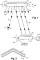
- Fig. 1 is a schematic illustration of a complete transmission and reception system, constructed according to a first preferred embodiment of the present invention.
- the transmitter 10 preferably mounted in a position where it can radiate into the whole of the volume to be covered, comprises a 3-dimensional retroreflector array 12, in front of which is disposed a gain material 14, preferably excited by means of an electrical excitation input 16, though other forms of excitation such as optical or chemical pumping can equally be used with suitable gain media.
- the gain material is preferably provided with anti-reflection optical coatings to improve its performance, as is known in the art.
- the excitation When the excitation generates a population inversion in the gain material 14, it will emit photons in all directions 18. In the absence of a receiver, these photons will generally be absorbed by the surroundings, and since their flux level is low, they present no safety hazard.
- the receiver 20 preferably mounted on the portable device to be powered, and with a data link connected to the device, comprises a partially reflective retro reflector 22, behind which is mounted a conversion device 24, such as a photovoltaic array, for converting optical power to electricity for use by the mobile device 26.
- the retroreflector may preferably be built of an array of smaller retroreflectors, each pointing in a different direction, so that the reflectance is more homogeneous as a function of spatial direction.
- Some of the photons emitted by the transmitter 10 will statistically be directed towards the receiver 20. These photons impinge on the receiver retroreflector 22, whose optical properties have been selected so that most of the incident photons are reflected back along their incident path 28, and the rest are transmitted through the retroreflector to the photoelectric conversion device 24, where they are converted to electricity for operating the mobile device, or for charging the batteries of the mobile device.
- the photons reflected back along their incident path then arrive back at the transmitter 10, where they first pass through the gain medium 14, causing more photons having the same quantum parameters (direction, wavelength, phase, and others) to be emitted, thus amplifying the radiation during this process.
- This amplified radiation then impinges on the transmitter retoreflector 12, from which it is again reflected back through the gain medium 14 and again amplified, and then back along the path 28 to the receiver, where some of it is again converted into electrical energy and the significant part of it is reflected back towards the transmitter again, such that the whole process is repeated again.
- the process continues as long as the amplification of the gain medium is sufficient to make up for the energy extracted from the beam and converted to power in the receiver, and for losses along the way.
- the system thus behaves like a panoramic, free-space laser, whose cavity extends between the generally fixed position transmitter and the receiver, which may be located anywhere in the region covered by the range of the transmitter, and which can be aligned in almost any direction so long as the retroreflector does have some angular part of its aperture aimed at the transmitter.
- the embodiment of Fig. 1 shows the converter 24 as a photoelectric converter providing electrical power to a mobile electronic device
- the system can also be used to simply deliver optical laser power directly to a remote point where it is needed, without any photoelectric conversion process to electricity.
- the converter 24 could preferably be an optical beam converter for directing the transmitted beam, or part of it, to one or more devices, which then utilize the radiation directly.
- Such a preferred embodiment could be used to deliver optical power on the floor of hospital operating theatres, or in a cosmetic laser surgery office, eliminating the need for bulky laser resonators, and thus providing a less cluttered environment.
- the open-space cavity of the present invention presents significantly reduced safety hazard. If a foreign object blocks the beam, some of the photons will be absorbed by the object, and if the blockage is sufficient to reduce the overall gain of the laser cavity to below unity, the lasing process will be interrupted, and the beam energy caused to decay almost instantaneously. Thus, if the user's head enters the beam sufficiently for this condition to be fulfilled, the radiation is blocked completely, and no reflected photons will reach the amplifier, thus stopping the directional radiation, and the transmitter will only continue to emit non-coherent photons in all directions, just as a lamp does.
- the transmission is generally eye safe, unlike that which would be achieved using a conventional laser, where a blocking eye would be located outside of the cavity, and would not therefore halt the lasing at all when inserted into the beam.
- one or more monitor detectors 29 can be disposed in the vicinity of the receiver unit.
- the function of these monitor detectors is to keep track of any unexpected changes in the radiation pattern around the region of the receiver unit. So long as the lasing is taking place uninterrupted, the detector or detectors 29 will detect the low level of residual radiation scattered out of the beam by the system and its surroundings.
- the monitor detector or detectors 29 will detect this change, and the system programmed to cut off the lasing almost instantaneously by shutting off the excitation to the gain material.
- the shut down can be programmed to last for a suitable time, such as a few seconds, to enable the intruding object to move from the beam path, before the power is restored.
- a detector or detectors 25 can also be implemented into the transmitting unit in order to decode data transmitted by the mobile device, or to provide a safety monitor similar to the detector 29 described above in connection with the receiver unit, or both.
- Another safety aspect of the present invention is the suppression of beams undergoing undesired reflections from surfaces inside the effective laser cavity.
- one such exemplary reflection is shown as a ray 27 reflected from the front surface of the gain medium 14, and which is shown entering the eye 21 of a person. Since the power of the intra-cavity radiation 28 is many times higher than the emitted useful power, even if the reflection coefficient of the front surface of the gain medium is reduced to a small fraction of 1%, as is possible with a correctly designed and applied anti-reflection coating, such undesired reflections could be of sufficient power to cause eye damage, or at least to require the safety classification of the system in a higher class than it would have been without the reflections.
- the first measure that can be taken to avoid such a risk is to reduce the number of surfaces that may reflect such a beam.
- prisms as the operative elements in the retroreflectors in the receiver or transmitter units, is not advised because the front surface of the prisms may reflect such a beam.
- a hollow corner cube retroreflector does not have such a front surface, and thus eliminates such reflected beams, though it may be more difficult to keep clean.
- use may be made of cat's eye retroreflectors, as their convex outer surface ensures that any reflected beam has a diverging form.
- a second measure is to design the system so that every such surface that may spuriously reflect such a beam is disposed so that the reflected beam would be blocked or attenuated.
- a preferred embodiment for achieving this is described hereinbelow in Fig. 8 .
- a third measure is to coat every such surface to reduce reflections therefrom to a minimum.
- a fourth measure is to use, where possible optically, surfaces that reflect an uncollimated expanding beam that have a reduced risk, as described for instance in relation to the cat's eye retroreflectors mentioned above..
- An additional method of limiting the energy is available by limiting the distance between the transmitter and receiver. If this is done, the maximal time before lasing stops may be calculated by the travel time of the light in the cavity back and forth between the transmitter unit and the receiver unit. The effect of this limited time is that if the beam is blocked, the effective "pulse length" of the beam until lasing is quashed is limited, thus making the potential damage limited, and, where relevant according to safety regulations, ensuring that the "laser pulse" is less than the threshold required for keeping the laser in a safer category.
- a pulse shorter than 100ns is considered to be safer then longer pulses, and ensures inclusion in a safer classification, it would be advisable to limit the distance between the transmitter and receiver to less than 15 meters, as the transit time over this distance would limit the pulse length in the event of a path of sight blockage to 100 ns.
- Limitation on the maximal distance can be done by carefully designing the retroreflectors so that beams returned are slightly focused, defocused, shifted or misaligned. Misalignment arises from imperfect performance of the retro-reflector, which, instead of returning an incident beam back exactly along its incident path angle, i.e. at 180 degrees from the incident direction, could reflect the beam at an angle with a small deviation from 180 degrees. That way above a certain distance, the beams spot on the transmitter and receiver will be bigger than the retro reflector array and the amount of reflected light will drop below the threshold necessary for lasing.
- Another possible method to limit the maximal operational distance is to actively measure the distance and add a mechanism to stop lasing if that distance exceeds a certain limit.
- the device may be desirable to limit the distance and power of the device so that it meets a certain laser safety class such as class 1 laser, which is, by definition, harmless to humans. Limiting the device in such a way would mean that the safety precautions that the user has to take may be eliminated completely or reduced. General practice is that the lower the laser class the safer the device is. It is preferable to use a class 1 laser over a class 2 laser, and so on.
- Laser safety regulations are updated from time to time and are different from country to country but generally, the safest class of laser is the preferable one for use in such a system.
- the safety requirements relevant to this invention are laser safety requirements. In most cases the power would be limited to class 1 laser limitations. However in industrial/military/research and other systems, this limitation may be changed if the proper safety precautions are taken.
- the relevant parameters are among others (depending on exact system design) wavelength, power, maximal distance between the receiver and the transmitter and reflections from different parts of the system
- the system would be a class one laser product (which is inherently assumed safe) if it does not allow for exposure to levels of laser radiation exceeding the maximal allowed exposure limit for a class 1 laser.
- a system would be inherently safe for consumer use as it presents no bigger hazard than a class 1 laser pointer, and would therefore be the most preferable configuration to use for a device for widespread domestic use. Furthermore, such a laser would not require the inconvenient use of safety goggles.
- the system is preferably constructed in such a way that, the internal pump laser radiation is not emitted in hazardous levels from the transmitter. This may be achieved by adding a filter which absorbs the pump wavelength or by careful design of the gain medium structure and thickness such that the majority of the pump laser energy is absorbed by the gain medium.
- a link by which the receiver is able to communicate at least some information to the transmitting unit could be messages such as "I am here", “please turn on”, “please turn off', "I am receiving X Watts", “I need Y watts” "my serial number is”, and so on.
- This communication link can either be through the modulation data link of the present invention, or it may be a separate wireless channel.
- FIG. 2 there is shown another preferred geometry of the power transmitter of Fig. 1 of this application, showing how the use of a folded geometry for the retroreflector 12 and the gain medium 14 is useful for positioning in the corner of a room, such that the volumetric coverage of the receiving space is improved.
- An optional transparent front cover 15 is shown to illustrate the protection of the transmission unit from damage or environmental pollution.
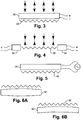
- Fig. 3 there is shown an alternative and preferred construction for the receiver unit, in which a partially transparent photovoltaic cell 30 is used, with the retroreflector 32 behind it to reflect the radiation transmitted through the photocell.
- Fig. 4 there is shown another preferred embodiment for the receiver power extraction from the transmitted beam.
- the energy converter 34 such as a photovoltaic cell
- the receiver retroreflector 36 is arranged around the periphery of the receiver retroreflector 36, and operates by absorbing some of the radiation which spills over from the main beam, analogously to the methods used to extract power from unstable resonator high power laser cavities.
- the transmitted beam is not blocked or limited by the power extraction and conversion element 34.
- this element is shown in the embodiment of Fig. 4 to be arranged around the retroreflector, it is to be understood that it can be positioned anywhere in the vicinity of the retroreflector where part of the lasing beam can be detected and extracted from the lasing cavity.
- a beam modulation device such as a liquid crystal cell 38, may preferably be positioned in front of the retroreflector 40 (in those embodiments where the retroreflector is at the front of the receiver), and is operative to modulate the light passing through it with the time varying data 42 to be impressed on the transmitted beam.
- Such a beam modulating device may also be used in the transmitter unit. However, for the transmitter unit, but it may be more convenient to simply modulate the gain material excitation power to impress data onto the beam transmitted to the mobile device.
- FIG. 6A and 6B show a number of further preferred retroreflector geometries for use in the system of the present invention.
- Fig. 6A shows one possible method to limit the maximal operational distance.
- the gain medium 61 is designed so that its front surface acts like a lens, slightly focusing the reflected beam into the cavity so that when the distance between the transmitter and receiver is significantly longer than the focal length, the beam will have diverged again and lasing conditions will cease to exist.
- the lens power is shown in Fig. 6A in an exaggerated manner; to schematically illustrate this embodiment.
- Fig 6B shows a further embodiment in which the retroreflector 62 and the gain medium 63 have a concave shape, such that the reflected beam is defocused down the cavity.
- the curvature is shown in an exaggerated manner also in Fig. 6B , in order to clearly illustrate the form of the embodiment.
- retroreflectors There are two common types of retroreflectors, corner-cube retroreflectors and cat's eye retroreflectors, although other types may also be used, such as phase conjugate mirrors, which ensure that even distorted wavefronts are returned in phase conjugation to the incident beam. It is preferable to use a corner-cube type retroreflector for these applications as the divergence of the reflected beam is smaller and the loss of light due to unwanted reflections is lower due to the lower number of surfaces. Surface reflections that may present a safety hazard should be reduced by one of the methods described herein above. This allows for higher gain and more accuracy in the maintenance of the transmission in the correct direction.
- Retro-reflectors can be measured by four technical parameters: (i) the field of view (the angles from/to which it is efficient), (ii) the reflectance divergence (the accuracy of retro-reflection), (iii) the efficiency (how much of the light is reflected) and (iv) the shift of the beam (the beam's center may be laterally shifted by a small distance).
- the field of view is also important, as well as its weight and volume. Both cube corners and cat eye retro-reflectors may be used as long as the efficiency still allows sufficient amplification of the beam. Cat's eye retro reflectors should be AR coated to increase their efficiency, the reflected beam from the front surface of a cat eye retroreflector is of wide angle and may require in some cases the device to be classified as a class 1 m laser product, which is also safe for use.
- the optimal value is preferably between 100 ⁇ Wavelength (minimum) and the gain medium diameter.
- the optimal laser gain medium 14 should have high gain to enable a small, efficient device.
- IR wavelengths are optimal because of ease of conversion to electricity.
- the maximal allowed exposure to laser power is different for different wavelengths, such that it is advantageous to use wavelengths that pose less danger.
- Specifically eye safe wavelengths such as the wavelengths longer than 1400nm and shorter than 2500nm are especially advantageous.
- Wavelengths that are absorbed or easily scattered by the atmosphere are not advised.
- wavelengths from 700-2500 nm are most preferred.
- Some gain mediums give low gain values per meter. Thus, for instance, HeNe provides approximately 3% (depending on pumping method, pressure, concentration and other parameters) and other gain media may provide higher values.
- the optical length of the gain medium determines the absolute gain in the medium. This gain has to compensate for the power extracted for use by the device, and optical losses on the way, so in order to achieve a small efficient device, high gain media are preferable.
- Such high gain media are usually solid state in nature, such as semiconductors used in laser applications, and crystals and glasses doped with rare earth elements such as Neodymium and Erbium, or Tantalum
- optical gain media which achieve population inversion by means of direct electrical excitation, and not optical, chemical or other excitation methods, which are achievable, but are more complex to execute.
- the gain medium should preferably be of low cost. Glasses doped with rare earth are especially preferred as they can be mass manufactured and shaped into various shapes. For all of the above reasons, semiconductor gain media are particularly advantageous.
- Small sheets of micro retro reflectors can be produced by injection molding, compression molding or other methods.
- the transmitter preferably comprises a retro-reflector made of many small corner reflectors (a device consisting of 3 reflecting surfaces at 90 degrees to each other).
- the surface of this retro reflector is preferably covered with a sheet of semiconductor gain medium, which could preferably be of GaAlAs, which lases in the infrared.
- the area of the retro-reflector should be big enough that the dimensions of a single corner reflector are significantly smaller than the dimensions of the transmitter itself, the number of reflecting cubes would preferably be in the range 50-50,000 cubes/surface.
- the retro-reflecting surface can be made by injection molding or other types of molding or machining methods.
- the device preferably has a light detector for monitoring the amounts of light emitted in directions other than that of the retroreflectors. These are used to detect the presence of a receiver and to interpret data transmitted by the receiver.
- the gain medium is excited preferably electrically, to create a population inversion and emission of random photons in all directions.
- the receiver preferably comprises a similar retro-reflector (of a smaller size) that reflects most, but not all the light back.
- the portion that passes the retro-reflector is converted to electrical power preferably by a photovoltaic cell, the generated electricity is then stored in a small rechargeable battery to allow for continuity of power for the device even when the transmitter link is broken.
- a liquid crystal cell is preferably placed to modulate the amount of reflected light, in order to transmit data.
- the retro-reflectors can be replaced with other types of retro-reflectors such as ball retro-reflectors or even 4 wave mixing retro-reflectors.
- the modulation of light is optional, and is only needed if data is to be transmitted on top of the energy transmitted.
- the light can be converted to power by voltaic cells or by diodes or by other devices.
- the battery is optional and is needed only in some cases, such as where the device should continue to operate even if the transmission link back is broken.
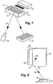
- FIG. 7 is a schematic illustration of another preferred embodiment of the current invention.
- a neodymium (or another rare earth) doped glass slab of gain medium 70 is molded in a way that at least one facet of it is shaped like a large number of corner cubes 71. That facet is coated with a highly reflective coating such as protected gold.
- Another facet 74 of the rare earth doped glass is used for pumping it, preferably using a diode laser 72 of suitable wavelength ( ⁇ 800nm in the case of Nd).
- the pumping facet is preferably diffusive to average out the pump power throughout the slab.
- At least one other facet of the glass 73, opposite to the retroreflector facet 71, is polished to high optical quality and coated with anti reflecting coating.
- the pump diode 72 is positioned such that its power is emitted into the glass slab 70, and the power is regulated so that pump power levels posing no danger are emitted through the glass.
- the glass slab 70 and pump diode 72 are fitted in a box having an entrance aperture and a beam block, arranged in a way that light entering through the aperture, and reflected from the glass surface is blocked by the beam block.
- the receiver is made of a semitransparent corner cube retro reflector array made of retroreflecting prisms so that the surface is flat and can be easily cleaned.
- the front surface the the prisms is coated for anti reflection so that reflected beams from it would not pose any danger to the users.
- the retroreflecting array is fit onto a photoelectric cell converting the light energy into electrical power.
- an SDL3470 laser diode supplied by SDL of San Jose, CA, USA, lasing at 808nm was driven by 18.5 Ampere of current supplied by a Lambda LLS 6008 power supply, supplied by Lambda Corporation of San Diego, CA, USA.
- the diode is cooled by a water cooling device.
- the light from the diode is directly coupled to a neodymium doped YLF crystal approximately 30mm x 3mm x 2mm in size, through its 2mm facet which is diffusive.
- the crystal contains a suitable concentration of Nd atoms.
- This configuration was tested using a hand-held corner cube hollow retroreflector 75, positioned about 1.60 meters from the slab 70.
- the retroreflector 75 was moved around a distance of approximately 10 cm to the left and right, up and down, and forwards and backwards. Lasing occurs between the retroreflectors and the slab and is detected by a Sony DCR IP7E video camera 76, capable of detecting IR radiation.
- An attempt to reproduce lasing with a hand held plane mirror resulted in no lasing at all.
- the undesired spurious reflection 77 from the surface of the slab, directed at the expected surface reflection angle can also be detected by the camera, although the power can be strong enough to saturate the camera detector.
- Fig. 8 illustrates schematically a system according to another preferred embodiment of the present invention, by which reflections from the front surface of the gain medium can be blocked such that they do not present any health hazard to persons within the transmission region.
- the transmitting unit 85 is similar to that shown in the embodiment of Fig. 1 , and comprises a retroreflector 80, positioned behind a gain medium 81.
- the transmitting unit is disposed within a shielded enclosure 82, constructed of materials non-reflective to the radiation being emitted.
- the transmitting unit is positioned such that it preferably faces the enclosure, and a clear aperture 83 in the enclosure, enables the transmitting unit to emit its radiation into the space to be covered.
- a receiving unit 84 preferably comprising a partially transparent retroreflector 86 and a photovoltaic cell 87, situated within this space, is in optical communication with the transmitting unit 85, as schematically indicated by the beam 88 between the transmitting unit and the receiver.
- the dimensions of the enclosure and transmitting unit are predetermined such that any radiation incident with a positive angle of incidence on the front face of the gain medium 81, is reflected from that front face, or from any other part of the transmitting unit, at a negative angle as depicted by the ray 89, and will be directed into the enclosure, and absorbed there, such that it cannot be propagated into the space.
- Beam block 82 blocks all possible reflections at negative angles, such that all reflections of incoming incident beams are blocked.
- this blocking embodiment ensures that spurious reflections from surfaces within the transmitting unit cannot cause any harm to persons within the transmission space.
- the transmitting unit is shown in the embodiment of Fig.8 , is directed at right angles to the general direction of the transmission space, and the enclosure is shown having a rectilinear geometry, it is to be understood that the invention is not meant to be limited by this configuration, and that any orientation angle and shape can be used, so long as the geometry of the transmitter and enclosure is arranged that radiation reflected from the front surface of the transmitting unit is not allowed to exit the enclosure.
- a similar spurious reflection blocking arrangement can also preferably be provided for the receiver unit.
- a method and apparatus are described for directing the radiation to a specific receiver out of more than one located within the space covered by the transmitting unit.
- Such a capability may be achieved by adaptation of the transmitter device.
- the distance of each receiver from the transmitter is usually different, causing the time it takes the light to reach the receiver and return to the transmitter to be different for each receiver. If the gain medium is modulated so that its gain characteristics will be sequentially switched to be higher and lower at the modulation frequency, any receiver that is located at a distance from the transmitter such that the round trip optical transit time of the radiation is equal to the period associated with the modulating frequency, will receive a larger portion of the energy transmitted.
- this is operable since if, at a certain moment in time, the gain is at its maximum, and the modulation frequency is such that the radiation from the transmitter travels to a particular receiver and back again, arriving just when the gain is at its maximum level again, then that particular receiver will be coupled at the optimum efficiency to the transmitter, and over the maximum time interval in correlation with the period of high gain of the gain medium, and will thus receive the optimum level of power.
- Other receivers which are not at that characteristic distance from the transmitter, will not be temporally coupled to the maximum gain periods, and so will receive less power.
- a non-limiting numerical example is now brought to illustrate this embodiment.
- Two receivers are used, one at 3 meters from the transmitter and one at 4.5 meters from it.
- the time taken for radiation to reach the first transmitter is of the order of 10ns.
- the time for a full round trip of light is 20ns.
- the cycle time for the 4.5 meter receiver is 30ns. If no modulation is made on the gain of the gain medium, the receiver returning the light more efficiently to the transmitter would be the dominant mode and will receive most of the energy. That could depend both on distance and on receiver orientation relative to the transmitting unit as well as other factors such as dust.
- the first method is to build the system so it has passive mode locking capabilities. By that means, the natural frequencies of the system will be generated by the system itself.
- the second method is to directly measure the distance of each receiver, by generating a modulated light pulse below the lasing threshold, and measuring the time taken for the pulse to return to the receiver. This is much similar to the way geographical surveys are done using retroreflectors.
- the third method is, once initial mode locking has been established with the correct receiver, to frequency modulate the central frequency and to control the central frequency with a Phase-locked loop on the feedback of the gain medium control system.
- the fourth method is to scan a range of frequencies, while getting a response back from the different receivers about the amount of power they receive as a function of the transmitted frequencies.
- each receiver may be equipped with a filter, limiting its wavelength response.
- the transmitter then may be adapted to choose a specific receiver by allowing higher gain for that specific wavelength, for instance, by use of a filter wheel or by changing other parameters of the system, such as pump wavelength or power, mechanical placement of parts or others, such that the desired wavelength is preferentially emitted.
- spatial filtering may be used, whereby a moving aperture, for instance, is added to the system, and is moved to limit the possible transmission of the system to only a limited predetermined region where the selected receiver is known to be located.
- a moving aperture for instance, is added to the system, and is moved to limit the possible transmission of the system to only a limited predetermined region where the selected receiver is known to be located.
- Such an aperture can be fitted on the transmitter unit, such as a directional tube or funnel, or on the receiver unit by adding a shutter thereto.
Claims (20)
- Ein System zum drahtlosen Senden von Lichtleistung an eine entfernte Vorrichtung (26), die in einem Raum angeordnet ist, Folgendes umfassend:eine Sendeeinheit (10), ausgebildet, um optische Strahlung (18) allgemein in den Raum zu lenken, wobei die Sendeeinheit (10) ein Verstärkungsmedium (14) umfasst, das eine vordere Fläche hat, die ausgebildet ist, um optische Strahlung allgemein zu dem Raum hin zu lenken, und eine hintere Fläche mit einem Rückstrahler (12) in optischer Verbindung damit; undeine Empfängereinheit (20), die verknüpft mit der Vorrichtung (26) und ausgebildet ist, um optische Strahlung zu empfangen, die von der Sendeeinheit (10) durch den Raum gestrahlt wird, und die einen Rückstrahler (22) umfasst, ausgebildet, um einen ersten Teil der optischen Strahlung, die von der Sendeeinheit (10) empfangen wird, in die Richtung der Sendeeinheit (10) zurückzustrahlen, so dass die Sendeeinheit (10) die optische Strahlung verstärkt, die von der Empfängereinheit (20) zurückreflektiert wird, und sie erneut in die Richtung der Empfängereinheit (20) sendet, und ausgebildet, um einen zweiten Teil der Strahlung zur Nutzung durch die Vorrichtung (26) zu übertragen;dadurch gekennzeichnet, dass der Abstand zwischen der vorderen und der hinteren Fläche des Verstärkungsmediums (14) wesentlich kleiner ist als mindestens eine seitliche Abmessung des Verstärkungsmediums (14).
- Ein System gemäß Anspruch 1, und wobei die Empfängereinheit (20) auch einen Spannungsadapter (24) umfasst, der den zweiten Teil der optischen Strahlung in elektrischen Strom umwandelt.
- Ein System gemäß Anspruch 1, und wobei der zweite Teil der optischen Strahlung als optische Leistung genutzt wird.
- Ein System gemäß einem beliebigen der obigen Ansprüche, und wobei das Verstärkungsmedium (14) entweder durch elektrische (16) oder durch optische Erregung (72) erregt wird.
- Ein System gemäß einem beliebigen der obigen Ansprüche, und wobei die Sendeeinheit (10) ausgebildet ist, um die gesendete optische Strahlung zu modulieren, so dass Daten an den Empfänger (20) gesendet werden können.
- Ein System gemäß Anspruch 5, und wobei die gesendete optische Strahlung entweder durch Modulation der Erregung des Verstärkungsmediums oder mit Hilfe eines Flüssigkristallmodulators (38) moduliert wird.
- Ein System gemäß einem beliebigen der obigen Ansprüche, und wobei die Empfängereinheit (20) ausgebildet ist, um die davon reflektierte optische Strahlung zu modulieren, so dass Daten an die Sendeeinheit (10) übertragen werden können.
- Ein System gemäß Anspruch 2, und wobei der Adapter (24) die Modulation der gesendeten optischen Strahlung in ein Datensignal zur Verwendung durch die mobile elektronische Vorrichtung (26) umwandelt.
- Ein System gemäß einem beliebigen der obigen Ansprüche, und wobei das Verstärkungsmedium (14) ein beliebiges von Folgendem ist: ein mit seltenen Erden dotiertes Glas, ein mit seltenen Erden dotierter Kristall, Nd:YAG, Ti:Saphir, Rubin, Er:YAG, Er:Glas oder ein Halbleiter.
- Ein System gemäß einem beliebigen der obigen Ansprüche, und wobei mindestens einer der Rückstrahler (12, 22) entweder ein Tripelspiegelrückstrahler oder ein Katzenaugenrückstrahler ist.
- Ein System gemäß einem beliebigen der obigen Ansprüche, und das weiter mindestens einen Detektor (29) umfasst, der außerhalb des optischen Pfades zwischen der Sendeeinheit (10) und der Empfängereinheit (20) angeordnet ist, wobei der Detektor (29) arbeitet, um die optische Strahlung zu begrenzen, wenn ein vordefinierter Änderungspegel der gesendeten Strahlung erfasst wird.
- Ein System gemäß einem beliebigen der obigen Ansprüche, und wobei die Sendeeinheit (10) ausgebildet ist, um eine begrenzte Reichweite zu haben, so dass die Zeit, die verstreicht, bevor die optische Strahlung durch ein Objekt im Pfad zwischen der Sendeeinheit (10) und der Empfängereinheit (20) gestoppt wird, entsprechend begrenzt wird.
- Ein System gemäß Anspruch 12, und wobei die verstreichende Zeit durch die Umlaufzeit der optischen Strahlung zwischen der Sendeeinheit (10) und der Empfängereinheit (20) bestimmt wird.
- Ein System gemäß Anspruch 12, und wobei die begrenzte Reichweite durch Folgendes erzeugt wird: entweder durch die Verwendung mindestens eines Rückstrahlers (12, 22), der ausgebildet ist, um einen einfallenden Strahl in mindestens einem aus einem fokussierten, defokussierten, verschobenen und falsch ausgerichteten Zustand zu reflektieren, oder durch die aktive Messung des Empfängerabstands von der Sendeeinheit (10) und die Verwendung des gemessenen Abstands, um die optische Strahlung zu begrenzen, wenn sie die begrenzte Reichweite überschreitet.
- Ein System gemäß einem beliebigen der Ansprüche 12 bis 14, und wobei das System lasersicher ist.
- Ein System gemäß einem beliebigen der obigen Ansprüche, und das weiter mindestens eine Strahlblockieranordnung (82) umfasst, die relativ zu der Sendeeinheit (10) und/oder der Empfängereinheit (20) so angeordnet ist, dass Reflexionen von Oberflächen innerhalb einer der Sendeeinheit (10) und der Empfängereinheit (20) nicht in den Raum emittiert werden.
- Ein System gemäß Anspruch 16, und wobei jeder Strahl, der in eine Richtung reflektiert wird, die nicht kollinear mit der Empfänger- und der Sendeeinheit (20, 10) ist, blockiert wird.
- Ein System gemäß einem beliebigen der obigen Ansprüche, und wobei das Verstärkungsmedium (14) mit einer vordefinierten Frequenz moduliert wird, so dass seine Verstärkung mit der Modulationsfrequenz zwischen einem höheren und einem niedrigeren Wert wechselt, so dass eine Empfängereinheit (20), die sich in einem charakteristischen Abstand von der Sendeeinheit (10) befindet, so dass die Umlaufzeit der optischen Strahlung zwischen der Sendeeinheit (10) und der Empfängereinheit (20) gleich dem mit der Modulationsfrequenz verknüpften Zeitraum ist, eine effizientere optische Kopplung mit der Sendeeinheit (10) hat als eine Empfängereinheit (20), die sich in einem anderen Abstand von der Sendeeinheit (10) befindet.
- Ein System gemäß Anspruch 18, und wobei die Empfängereinheit (20), die in dem charakteristischen Abstand von der Sendeeinheit (10) positioniert ist, mit der Sendeeinheit (10) modengekoppelt ist.
- Ein System gemäß Anspruch 18, wobei optisches Lasern begrenzt ist auf zwischen einer vordefinierten Empfängereinheit (20) und der Sendeeinheit (10), entweder durch Modenkopplung oder durch Auswahl der Modulationsfrequenz.
Applications Claiming Priority (2)
| Application Number | Priority Date | Filing Date | Title |
|---|---|---|---|
| US72064805P | 2005-09-27 | 2005-09-27 | |
| PCT/IL2006/001131 WO2007036937A2 (en) | 2005-09-27 | 2006-09-27 | Directional light transmitter and receiver |
Publications (3)
| Publication Number | Publication Date |
|---|---|
| EP1929678A2 EP1929678A2 (de) | 2008-06-11 |
| EP1929678A4 EP1929678A4 (de) | 2013-09-11 |
| EP1929678B1 true EP1929678B1 (de) | 2018-03-14 |
Family
ID=37900170
Family Applications (1)
| Application Number | Title | Priority Date | Filing Date |
|---|---|---|---|
| EP06796128.4A Active EP1929678B1 (de) | 2005-09-27 | 2006-09-27 | Gerichteter lichtsender und -empfänger |
Country Status (3)
| Country | Link |
|---|---|
| US (1) | US9705606B2 (de) |
| EP (1) | EP1929678B1 (de) |
| WO (1) | WO2007036937A2 (de) |
Cited By (2)
| Publication number | Priority date | Publication date | Assignee | Title |
|---|---|---|---|---|
| WO2020148772A1 (en) * | 2019-01-17 | 2020-07-23 | Wi-Charge Ltd | Safe enclosures for wireless power supply |
| US11821251B2 (en) | 2020-09-17 | 2023-11-21 | Gmi Holdings, Inc. | Laser powered door operating system |
Families Citing this family (38)
| Publication number | Priority date | Publication date | Assignee | Title |
|---|---|---|---|---|
| US9705606B2 (en) * | 2005-09-27 | 2017-07-11 | Wi-Charge, Ltd. | Directional light transmitter and receiver |
| KR100860667B1 (ko) * | 2006-11-07 | 2008-09-26 | 삼성전자주식회사 | 가시광 통신을 위한 휴대용 무선 단말기 |
| US8315526B2 (en) * | 2007-06-18 | 2012-11-20 | Hewlett-Packard Development Company, L.P. | Misalignment tolerant free space optical transceiver |
| US8525097B2 (en) * | 2008-01-03 | 2013-09-03 | Wi-Charge Ltd. | Wireless laser system for power transmission utilizing a gain medium between retroreflectors |
| KR101479783B1 (ko) * | 2008-09-01 | 2015-01-08 | 삼성전자주식회사 | 가시광 통신에서 역반사기를 이용한 통신 링크 정렬 방법 및 장치 |
| US9079494B2 (en) | 2010-07-01 | 2015-07-14 | Mill Mountain Capital, LLC | Systems, devices and methods for vehicles |
| US8760499B2 (en) * | 2011-04-29 | 2014-06-24 | Austin Russell | Three-dimensional imager and projection device |
| US8570372B2 (en) * | 2011-04-29 | 2013-10-29 | Austin Russell | Three-dimensional imager and projection device |
| CN107017550B (zh) * | 2011-06-13 | 2020-01-10 | Wi-电荷有限公司 | 空间分布式激光器共振器 |
| US9356173B2 (en) | 2012-08-31 | 2016-05-31 | Sandia Corporation | Dynamically reconfigurable photovoltaic system |
| DE102012021585A1 (de) | 2012-10-23 | 2014-03-20 | Astrium Gmbh | Verfahren zur drahtlosen Energieübertragung in geschlossenen Räumen |
| EP3982558A1 (de) | 2015-02-02 | 2022-04-13 | Wi-Charge Ltd. | Optische leistungsempfänger |
| WO2016187357A1 (en) | 2015-05-18 | 2016-11-24 | Lasermotive, Inc. | Locating power receivers |
| CN106357347B (zh) * | 2015-07-15 | 2021-05-11 | 弗莱克斯电子有限责任公司 | 光通信、音频传输和充电系统 |
| US9941965B2 (en) * | 2015-07-15 | 2018-04-10 | Flextronics Ap, Llc | Laser and optical charging and communications device and method of use |
| US9312701B1 (en) | 2015-07-16 | 2016-04-12 | Wi-Charge Ltd | System for optical wireless power supply |
| CN114977541A (zh) * | 2015-08-24 | 2022-08-30 | Wi-电荷有限公司 | 无线功率分配系统 |
| JPWO2017056469A1 (ja) * | 2015-09-29 | 2018-07-12 | パナソニックIpマネジメント株式会社 | 光源装置および投光装置 |
| TWI578722B (zh) * | 2015-11-23 | 2017-04-11 | 財團法人資訊工業策進會 | Optical communication system and optical communication transmission device |
| CN115242304A (zh) | 2015-12-30 | 2022-10-25 | 艾伦神火公司 | 光学窄播 |
| US11356183B2 (en) * | 2016-03-14 | 2022-06-07 | Wi-Charge Ltd. | System for optical wireless power supply |
| EP4362352A2 (de) | 2016-04-11 | 2024-05-01 | Wi-Charge Ltd. | System zur optischen drahtlosen stromversorgung |
| EP4297294A3 (de) * | 2017-05-15 | 2024-02-21 | Wi-Charge Ltd. | Flexibles verwaltungssystem für optische drahtlose energieversorgung |
| US9853740B1 (en) | 2017-06-06 | 2017-12-26 | Surefire Llc | Adaptive communications focal plane array |
| US11070298B2 (en) * | 2017-09-28 | 2021-07-20 | Wi-Charge Ltd. | Fail-safe optical wireless power supply |
| WO2019082052A2 (en) * | 2017-10-23 | 2019-05-02 | Lakediamond Sa | ENERGY TRANSFER DEVICE, ENERGY COLLECTION DEVICE, AND ENERGY BEAM FORMING SYSTEM |
| FR3075523B1 (fr) * | 2017-12-15 | 2020-01-10 | Alessandro Manneschi | Detecteur double technologie comprenant un capteur inductif et un radar |
| US10250948B1 (en) | 2018-01-05 | 2019-04-02 | Aron Surefire, Llc | Social media with optical narrowcasting |
| US10473439B2 (en) | 2018-01-05 | 2019-11-12 | Aron Surefire, Llc | Gaming systems and methods using optical narrowcasting |
| US10236986B1 (en) | 2018-01-05 | 2019-03-19 | Aron Surefire, Llc | Systems and methods for tiling free space optical transmissions |
| US11709383B2 (en) | 2018-06-12 | 2023-07-25 | Raymond Hoheisel | Optical communication and power generation device and method |
| CN112514182A (zh) | 2018-08-07 | 2021-03-16 | 古河电气工业株式会社 | 光功率传输装置 |
| US20240097498A9 (en) * | 2019-04-19 | 2024-03-21 | Guru, Inc. | Adaptive roaming and articulating generating unit for wireless power transfer |
| KR102168373B1 (ko) * | 2019-05-24 | 2020-10-22 | 세종대학교산학협력단 | 무선 광 충전 시스템 및 그 충전 방법 |
| US11266276B1 (en) * | 2020-01-06 | 2022-03-08 | Gojo Industries, Inc. | Touch free dispensers powered by focused energy signals |
| CN113572525B (zh) * | 2020-04-28 | 2022-11-04 | 华为技术有限公司 | 一种通信方法及系统 |
| IL287976A (en) * | 2021-11-09 | 2023-06-01 | Wi Charge Ltd | Scanning mirror for laser power transmission system |
| CN113847987B (zh) * | 2021-11-16 | 2023-12-15 | 电子科技大学 | 一种红外和可见光集成宽光谱荧光测量方法 |
Family Cites Families (68)
| Publication number | Priority date | Publication date | Assignee | Title |
|---|---|---|---|---|
| US514168A (en) | 1894-02-06 | Nikola tesla | ||
| US593138A (en) | 1897-11-02 | Nikola Tesla | Electrical Transformer | |
| US645576A (en) | 1897-09-02 | 1900-03-20 | Nikola Tesla | System of transmission of electrical energy. |
| US685955A (en) | 1899-06-24 | 1901-11-05 | Nikola Tesla | Apparatus for utilizing effects transmitted from a distance to a receiving device through natural media. |
| US685956A (en) | 1899-08-01 | 1901-11-05 | Nikola Tesla | Apparatus for utilizing effects transmitted through natural media. |
| US685954A (en) | 1899-08-01 | 1901-11-05 | Nikola Tesla | Method of utilizing effects transmitted through natural media. |
| US787412A (en) | 1900-05-16 | 1905-04-18 | Nikola Tesla | Art of transmitting electrical energy through the natural mediums. |
| US685957A (en) | 1901-03-21 | 1901-11-05 | Nikola Tesla | Apparatus for the utilization of radiant energy. |
| US685593A (en) | 1901-04-19 | 1901-10-29 | Frank A Franklin | Process of reclaiming pulp. |
| US1119732A (en) | 1907-05-04 | 1914-12-01 | Nikola Tesla | Apparatus for transmitting electrical energy. |
| US3215842A (en) * | 1963-04-18 | 1965-11-02 | Numa E Thomas | Optical communications system |
| US3566126A (en) * | 1967-11-29 | 1971-02-23 | Sylvania Electric Prod | Acquisition and tracking laser communication system |
| US4209689A (en) * | 1969-06-04 | 1980-06-24 | Hughes Aircraft Company | Laser secure communications system |
| DE2453077B2 (de) * | 1974-11-08 | 1976-09-02 | Precitronic Gesellschaft für Feinmechanik und Electronic mbH, 2000 Hamburg | Empfangs-sendeeinrichtung fuer die informationsuebermittlung mittels gebuendelter, modulierter lichtstrahlen |
| US4131791A (en) * | 1975-12-08 | 1978-12-26 | General Electric Company | Search and locate system |
| US4114151A (en) * | 1976-09-14 | 1978-09-12 | Alfa-Laval Company Limited | Passive transponder apparatus for use in an interrogator-responder system |
| US4361911A (en) * | 1981-05-21 | 1982-11-30 | The United States Of American As Represented By The Secretary Of The Army | Laser retroreflector system for identification of friend or foe |
| US4866781A (en) * | 1983-04-01 | 1989-09-12 | Honeywell Inc. | Method and means of identifying objects with retro-reflected light |
| DE3319158A1 (de) * | 1983-05-26 | 1984-11-29 | Precitronic Gesellschaft für Feinmechanik und Electronic mbH, 2000 Hamburg | System zur elektrooptischen informationsuebertragung |
| DE3328335A1 (de) * | 1983-08-05 | 1985-02-14 | Messerschmitt-Bölkow-Blohm GmbH, 8012 Ottobrunn | Datenfernueberwachungssystem |
| CH663287A5 (de) * | 1984-05-03 | 1987-11-30 | Landis & Gyr Ag | Einrichtung mit kontaktloser informationsuebertragung zwischen einem identifikator und einem identifikanden. |
| US4777660A (en) * | 1984-11-06 | 1988-10-11 | Optelecom Incorporated | Retroreflective optical communication system |
| US4983021A (en) * | 1988-08-10 | 1991-01-08 | Fergason James L | Modulated retroreflector system |
| US6025060A (en) * | 1988-08-30 | 2000-02-15 | Onyx Optics, Inc. | Method and apparatus for composite gemstones |
| EP0387383B1 (de) * | 1989-03-17 | 1995-05-24 | Siemens Aktiengesellschaft | Autarkes photonengetriebenes Bauelement |
| JP2899013B2 (ja) * | 1989-07-03 | 1999-06-02 | 俊弘 津村 | 移動体に対する位置情報伝達システム |
| US5023477A (en) * | 1990-02-01 | 1991-06-11 | Hughes Aircraft Company | Transient energy self-pumped conjugator and method |
| US5193201A (en) * | 1990-04-23 | 1993-03-09 | Tymes Laroy | System for converting a received modulated light into both power for the system and image data displayed by the system |
| US5121242A (en) * | 1991-02-04 | 1992-06-09 | Martin Marietta Corporation | Retro-reflective optical transceiver |
| US5251221A (en) | 1992-08-10 | 1993-10-05 | Hughes Aircraft Company | Self aligning intracavity Raman laser |
| IL108506A (en) * | 1994-02-01 | 1997-06-10 | Yeda Res & Dev | Solar energy plant |
| US5461637A (en) | 1994-03-16 | 1995-10-24 | Micracor, Inc. | High brightness, vertical cavity semiconductor lasers |
| US5528409A (en) * | 1994-10-13 | 1996-06-18 | Nt International, Inc. | Fiber-optic interface system |
| DE19510780A1 (de) | 1995-03-24 | 1996-09-26 | Stasys Malkevicius | Drahtloses Elektroenergie-Übertragungssystem |
| US5819164A (en) * | 1996-01-29 | 1998-10-06 | The United States Of America As Represented By The Secretary Of The Army | Modulated retroreflection system for secure communication and identification |
| CA2279934A1 (en) * | 1997-02-11 | 1998-08-13 | Scientific Generics Limited | Signalling system |
| US5926494A (en) * | 1997-04-11 | 1999-07-20 | Hughes Electronics Corporation | Laser systems with improved performance and reduced parasitics and method |
| US6381055B1 (en) | 1998-04-16 | 2002-04-30 | At&T Corp. | Transceiver positioning in free-space optical networks |
| GB9810039D0 (en) * | 1998-05-11 | 1998-07-08 | Isis Innovation | Communications device |
| FR2781613B1 (fr) | 1998-07-27 | 2000-10-06 | Photonetics | Laser en espace libre avec sortie fibre autoalignee |
| EP1218977A1 (de) * | 1999-09-29 | 2002-07-03 | Optical Technologies Italia S.p.A. | Verfahren zur herstellung eines faserlasers |
| US6493123B1 (en) * | 1999-10-27 | 2002-12-10 | Northrop Grumman Corporation | Modulated-retroreflector based optical identification system |
| EP1236196A1 (de) * | 1999-12-07 | 2002-09-04 | Moshe Klotz | Anordnung mit ausseraxialen lichtsensoren |
| US6339605B1 (en) * | 2000-02-16 | 2002-01-15 | The Boeing Company | Active mirror amplifier system and method for a high-average power laser system |
| US6388803B1 (en) * | 2000-03-02 | 2002-05-14 | Agere Systems Guardian Corp. | Article comprising a broad band optical amplifier |
| JP2003531515A (ja) * | 2000-04-07 | 2003-10-21 | ザ・リージェンツ・オブ・ジ・ユニバーシティ・オブ・カリフォルニア | 遠隔呼掛け高データ転送速度自由空間レーザ通信リンク |
| DE10085455T1 (de) * | 2000-04-14 | 2003-02-27 | Fujitsu Ltd | Optische Positionsdetektiervorrichtung und Aufzeichnungsmedium |
| US6407535B1 (en) | 2000-09-08 | 2002-06-18 | The Regents Of The University Of California | System for beaming power from earth to a high altitude platform |
| WO2002025358A2 (en) | 2000-09-22 | 2002-03-28 | Movaz Networks, Inc. | Variable transmission multi-channel optical switch |
| EP1391014B1 (de) * | 2000-09-29 | 2004-12-29 | Coherent Technologies, Inc. | Leistungsskalierbare wellenleiterverstärker- und laserbauelemente |
| US7660534B2 (en) | 2001-06-15 | 2010-02-09 | Salah Al-Chalabi | Optical communication device and system using optical power and signals |
| US7489865B2 (en) * | 2002-02-01 | 2009-02-10 | Cubic Corporation | Integrated optical communication and range finding system and applications thereof |
| US6906495B2 (en) | 2002-05-13 | 2005-06-14 | Splashpower Limited | Contact-less power transfer |
| US7831152B2 (en) * | 2002-06-04 | 2010-11-09 | Finisar Corporation | Optical transceiver |
| US6979088B2 (en) * | 2002-06-11 | 2005-12-27 | The United States Of America As Represented By The Secretary Of The Navy | Multipass optical retroreflector and method of using |
| ITMI20022211A1 (it) * | 2002-10-18 | 2004-04-19 | Cit Alcatel | Regolazione della potenza irradiata su un telescopio di |
| BRPI0316651B1 (pt) * | 2002-11-26 | 2016-12-06 | Solaren Corp | sistema de alimentação elétrica espacial, e, método para alinhar elementos de sistema de alimentação elétrica |
| US6798716B1 (en) | 2003-06-19 | 2004-09-28 | Bc Systems, Inc. | System and method for wireless electrical power transmission |
| US7085303B2 (en) * | 2003-10-16 | 2006-08-01 | The Boeing Company | Laser with combined lens and birefringence compensator |
| US7130320B2 (en) * | 2003-11-13 | 2006-10-31 | Mitutoyo Corporation | External cavity laser with rotary tuning element |
| US7693426B2 (en) * | 2003-12-18 | 2010-04-06 | Hewlett-Packard Development Company, L.P. | Laser-based communications with a remote information source |
| US7360703B2 (en) * | 2004-09-23 | 2008-04-22 | Ut-Battelle, Llc | Laser scanning system for object monitoring |
| US7609249B2 (en) * | 2005-04-21 | 2009-10-27 | Avago Technologies Ecbu Ip (Singapore) Pte. Ltd. | Position determination utilizing a cordless device |
| US7603041B2 (en) * | 2005-06-09 | 2009-10-13 | Cubic Corporation | Temperature compensated dynamic optical tag modulator system and method |
| US9705606B2 (en) * | 2005-09-27 | 2017-07-11 | Wi-Charge, Ltd. | Directional light transmitter and receiver |
| US7912369B2 (en) * | 2006-10-09 | 2011-03-22 | Verizon Services Corp. | Optical signal shutoff mechanism and associated system |
| JP4098341B1 (ja) * | 2006-12-28 | 2008-06-11 | 北陽電機株式会社 | 走査式測距装置の光学窓汚れ検出装置 |
| US7804877B2 (en) * | 2007-05-18 | 2010-09-28 | Cu Aerospace, Llc | Atomic lasers with exciplex assisted absorption |
-
2006
- 2006-09-27 US US12/088,385 patent/US9705606B2/en active Active
- 2006-09-27 WO PCT/IL2006/001131 patent/WO2007036937A2/en active Application Filing
- 2006-09-27 EP EP06796128.4A patent/EP1929678B1/de active Active
Non-Patent Citations (1)
| Title |
|---|
| None * |
Cited By (2)
| Publication number | Priority date | Publication date | Assignee | Title |
|---|---|---|---|---|
| WO2020148772A1 (en) * | 2019-01-17 | 2020-07-23 | Wi-Charge Ltd | Safe enclosures for wireless power supply |
| US11821251B2 (en) | 2020-09-17 | 2023-11-21 | Gmi Holdings, Inc. | Laser powered door operating system |
Also Published As
| Publication number | Publication date |
|---|---|
| US20090103925A1 (en) | 2009-04-23 |
| WO2007036937A3 (en) | 2009-09-03 |
| WO2007036937A2 (en) | 2007-04-05 |
| EP1929678A4 (de) | 2013-09-11 |
| US9705606B2 (en) | 2017-07-11 |
| EP1929678A2 (de) | 2008-06-11 |
Similar Documents
| Publication | Publication Date | Title |
|---|---|---|
| EP1929678B1 (de) | Gerichteter lichtsender und -empfänger | |
| US10404103B2 (en) | Wireless laser system for power transmission with gain medium control based on beam power or shape | |
| KR102628061B1 (ko) | 광학적 무선 전력 공급을 위한 시스템 | |
| US7224905B2 (en) | Remotely-interrogated high data rate free space laser communications link | |
| KR102399819B1 (ko) | 광 무선 전력 공급장치용 시스템 | |
| CN107017550B (zh) | 空间分布式激光器共振器 | |
| KR102455846B1 (ko) | 광 무선 전력 공급장치용 시스템 | |
| US10790632B2 (en) | Distributed coupled resonator laser | |
| Javed et al. | Long-range wireless optical power transfer system using an EDFA | |
| CN110994814A (zh) | 一种基于望远镜光学调制器的远距离共振光无线供能装置 | |
| CN113300491B (zh) | 一种可多点接入的激光无线能量传输系统 | |
| Kirubakaran et al. | Extending uav's operational time through laser beam charging: System model analysis | |
| Javed et al. | EDFA-enabled resonance beam charging at 1550 nm for improved efficiency, safety, and performance | |
| Javed et al. | Efficient and safe infrared wireless power transfer using resonant beam coupling with fiber-based power amplification in optical systems at 1550 nm for improved efficiency, safety, and performance | |
| Titar | An open resonator system for the free-space laser communication | |
| PL237841B1 (pl) | Hybrydowy układ komunikacji radiowej i optycznej w otwartej przestrzeni |
Legal Events
| Date | Code | Title | Description |
|---|---|---|---|
| PUAI | Public reference made under article 153(3) epc to a published international application that has entered the european phase |
Free format text: ORIGINAL CODE: 0009012 |
|
| 17P | Request for examination filed |
Effective date: 20080328 |
|
| AK | Designated contracting states |
Kind code of ref document: A2 Designated state(s): AT BE BG CH CY CZ DE DK EE ES FI FR GB GR HU IE IS IT LI LT LU LV MC NL PL PT RO SE SI SK TR |
|
| AX | Request for extension of the european patent |
Extension state: AL BA HR MK RS |
|
| R17D | Deferred search report published (corrected) |
Effective date: 20090903 |
|
| RIC1 | Information provided on ipc code assigned before grant |
Ipc: H02N 6/00 20060101AFI20090910BHEP |
|
| RAP1 | Party data changed (applicant data changed or rights of an application transferred) |
Owner name: WI-CHARGE LTD. |
|
| RIN1 | Information on inventor provided before grant (corrected) |
Inventor name: WI-CHARGE LTD. |
|
| DAX | Request for extension of the european patent (deleted) | ||
| A4 | Supplementary search report drawn up and despatched |
Effective date: 20130814 |
|
| RIC1 | Information provided on ipc code assigned before grant |
Ipc: H04B 10/80 20130101ALI20130808BHEP Ipc: H02N 6/00 20060101AFI20130808BHEP |
|
| 17Q | First examination report despatched |
Effective date: 20161014 |
|
| REG | Reference to a national code |
Ref country code: DE Ref legal event code: R079 Ref document number: 602006054921 Country of ref document: DE Free format text: PREVIOUS MAIN CLASS: H04J0001000000 Ipc: H04B0010112000 |
|
| GRAP | Despatch of communication of intention to grant a patent |
Free format text: ORIGINAL CODE: EPIDOSNIGR1 |
|
| RIC1 | Information provided on ipc code assigned before grant |
Ipc: H04B 10/00 20130101ALI20170731BHEP Ipc: H04B 10/112 20130101AFI20170731BHEP |
|
| INTG | Intention to grant announced |
Effective date: 20170830 |
|
| RIN1 | Information on inventor provided before grant (corrected) |
Inventor name: ALPERT, ORTAL |
|
| GRAS | Grant fee paid |
Free format text: ORIGINAL CODE: EPIDOSNIGR3 |
|
| GRAA | (expected) grant |
Free format text: ORIGINAL CODE: 0009210 |
|
| AK | Designated contracting states |
Kind code of ref document: B1 Designated state(s): AT BE BG CH CY CZ DE DK EE ES FI FR GB GR HU IE IS IT LI LT LU LV MC NL PL PT RO SE SI SK TR |
|
| REG | Reference to a national code |
Ref country code: GB Ref legal event code: FG4D |
|
| REG | Reference to a national code |
Ref country code: CH Ref legal event code: EP Ref country code: AT Ref legal event code: REF Ref document number: 979812 Country of ref document: AT Kind code of ref document: T Effective date: 20180315 |
|
| REG | Reference to a national code |
Ref country code: IE Ref legal event code: FG4D |
|
| REG | Reference to a national code |
Ref country code: DE Ref legal event code: R096 Ref document number: 602006054921 Country of ref document: DE |
|
| RAP2 | Party data changed (patent owner data changed or rights of a patent transferred) |
Owner name: WI-CHARGE LTD. |
|
| REG | Reference to a national code |
Ref country code: NL Ref legal event code: MP Effective date: 20180314 |
|
| REG | Reference to a national code |
Ref country code: LT Ref legal event code: MG4D |
|
| PG25 | Lapsed in a contracting state [announced via postgrant information from national office to epo] |
Ref country code: CY Free format text: LAPSE BECAUSE OF FAILURE TO SUBMIT A TRANSLATION OF THE DESCRIPTION OR TO PAY THE FEE WITHIN THE PRESCRIBED TIME-LIMIT Effective date: 20180314 Ref country code: FI Free format text: LAPSE BECAUSE OF FAILURE TO SUBMIT A TRANSLATION OF THE DESCRIPTION OR TO PAY THE FEE WITHIN THE PRESCRIBED TIME-LIMIT Effective date: 20180314 Ref country code: LT Free format text: LAPSE BECAUSE OF FAILURE TO SUBMIT A TRANSLATION OF THE DESCRIPTION OR TO PAY THE FEE WITHIN THE PRESCRIBED TIME-LIMIT Effective date: 20180314 Ref country code: ES Free format text: LAPSE BECAUSE OF FAILURE TO SUBMIT A TRANSLATION OF THE DESCRIPTION OR TO PAY THE FEE WITHIN THE PRESCRIBED TIME-LIMIT Effective date: 20180314 |
|
| REG | Reference to a national code |
Ref country code: DE Ref legal event code: R082 Ref document number: 602006054921 Country of ref document: DE Representative=s name: FARAGO PATENTANWALTS- UND RECHTSANWALTSGESELLS, DE Ref country code: DE Ref legal event code: R082 Ref document number: 602006054921 Country of ref document: DE Representative=s name: FARAGO PATENTANWAELTE, DE Ref country code: DE Ref legal event code: R081 Ref document number: 602006054921 Country of ref document: DE Owner name: WI-CHARGE LTD., IL Free format text: FORMER OWNER: WI-CHARGE LTD., JERUSALEM, IL |
|
| REG | Reference to a national code |
Ref country code: AT Ref legal event code: MK05 Ref document number: 979812 Country of ref document: AT Kind code of ref document: T Effective date: 20180314 |
|
| PG25 | Lapsed in a contracting state [announced via postgrant information from national office to epo] |
Ref country code: LV Free format text: LAPSE BECAUSE OF FAILURE TO SUBMIT A TRANSLATION OF THE DESCRIPTION OR TO PAY THE FEE WITHIN THE PRESCRIBED TIME-LIMIT Effective date: 20180314 Ref country code: SE Free format text: LAPSE BECAUSE OF FAILURE TO SUBMIT A TRANSLATION OF THE DESCRIPTION OR TO PAY THE FEE WITHIN THE PRESCRIBED TIME-LIMIT Effective date: 20180314 Ref country code: BG Free format text: LAPSE BECAUSE OF FAILURE TO SUBMIT A TRANSLATION OF THE DESCRIPTION OR TO PAY THE FEE WITHIN THE PRESCRIBED TIME-LIMIT Effective date: 20180614 Ref country code: GR Free format text: LAPSE BECAUSE OF FAILURE TO SUBMIT A TRANSLATION OF THE DESCRIPTION OR TO PAY THE FEE WITHIN THE PRESCRIBED TIME-LIMIT Effective date: 20180615 |
|
| REG | Reference to a national code |
Ref country code: FR Ref legal event code: PLFP Year of fee payment: 13 |
|
| PG25 | Lapsed in a contracting state [announced via postgrant information from national office to epo] |
Ref country code: RO Free format text: LAPSE BECAUSE OF FAILURE TO SUBMIT A TRANSLATION OF THE DESCRIPTION OR TO PAY THE FEE WITHIN THE PRESCRIBED TIME-LIMIT Effective date: 20180314 Ref country code: PL Free format text: LAPSE BECAUSE OF FAILURE TO SUBMIT A TRANSLATION OF THE DESCRIPTION OR TO PAY THE FEE WITHIN THE PRESCRIBED TIME-LIMIT Effective date: 20180314 Ref country code: EE Free format text: LAPSE BECAUSE OF FAILURE TO SUBMIT A TRANSLATION OF THE DESCRIPTION OR TO PAY THE FEE WITHIN THE PRESCRIBED TIME-LIMIT Effective date: 20180314 Ref country code: NL Free format text: LAPSE BECAUSE OF FAILURE TO SUBMIT A TRANSLATION OF THE DESCRIPTION OR TO PAY THE FEE WITHIN THE PRESCRIBED TIME-LIMIT Effective date: 20180314 |
|
| PG25 | Lapsed in a contracting state [announced via postgrant information from national office to epo] |
Ref country code: SK Free format text: LAPSE BECAUSE OF FAILURE TO SUBMIT A TRANSLATION OF THE DESCRIPTION OR TO PAY THE FEE WITHIN THE PRESCRIBED TIME-LIMIT Effective date: 20180314 Ref country code: AT Free format text: LAPSE BECAUSE OF FAILURE TO SUBMIT A TRANSLATION OF THE DESCRIPTION OR TO PAY THE FEE WITHIN THE PRESCRIBED TIME-LIMIT Effective date: 20180314 Ref country code: CZ Free format text: LAPSE BECAUSE OF FAILURE TO SUBMIT A TRANSLATION OF THE DESCRIPTION OR TO PAY THE FEE WITHIN THE PRESCRIBED TIME-LIMIT Effective date: 20180314 |
|
| REG | Reference to a national code |
Ref country code: DE Ref legal event code: R097 Ref document number: 602006054921 Country of ref document: DE |
|
| PG25 | Lapsed in a contracting state [announced via postgrant information from national office to epo] |
Ref country code: PT Free format text: LAPSE BECAUSE OF FAILURE TO SUBMIT A TRANSLATION OF THE DESCRIPTION OR TO PAY THE FEE WITHIN THE PRESCRIBED TIME-LIMIT Effective date: 20180716 |
|
| PLBE | No opposition filed within time limit |
Free format text: ORIGINAL CODE: 0009261 |
|
| STAA | Information on the status of an ep patent application or granted ep patent |
Free format text: STATUS: NO OPPOSITION FILED WITHIN TIME LIMIT |
|
| PG25 | Lapsed in a contracting state [announced via postgrant information from national office to epo] |
Ref country code: DK Free format text: LAPSE BECAUSE OF FAILURE TO SUBMIT A TRANSLATION OF THE DESCRIPTION OR TO PAY THE FEE WITHIN THE PRESCRIBED TIME-LIMIT Effective date: 20180314 |
|
| 26N | No opposition filed |
Effective date: 20181217 |
|
| PG25 | Lapsed in a contracting state [announced via postgrant information from national office to epo] |
Ref country code: SI Free format text: LAPSE BECAUSE OF FAILURE TO SUBMIT A TRANSLATION OF THE DESCRIPTION OR TO PAY THE FEE WITHIN THE PRESCRIBED TIME-LIMIT Effective date: 20180314 |
|
| PG25 | Lapsed in a contracting state [announced via postgrant information from national office to epo] |
Ref country code: MC Free format text: LAPSE BECAUSE OF FAILURE TO SUBMIT A TRANSLATION OF THE DESCRIPTION OR TO PAY THE FEE WITHIN THE PRESCRIBED TIME-LIMIT Effective date: 20180314 |
|
| REG | Reference to a national code |
Ref country code: CH Ref legal event code: PL |
|
| REG | Reference to a national code |
Ref country code: BE Ref legal event code: MM Effective date: 20180930 |
|
| PG25 | Lapsed in a contracting state [announced via postgrant information from national office to epo] |
Ref country code: LU Free format text: LAPSE BECAUSE OF NON-PAYMENT OF DUE FEES Effective date: 20180927 |
|
| PG25 | Lapsed in a contracting state [announced via postgrant information from national office to epo] |
Ref country code: BE Free format text: LAPSE BECAUSE OF NON-PAYMENT OF DUE FEES Effective date: 20180930 Ref country code: CH Free format text: LAPSE BECAUSE OF NON-PAYMENT OF DUE FEES Effective date: 20180930 Ref country code: LI Free format text: LAPSE BECAUSE OF NON-PAYMENT OF DUE FEES Effective date: 20180930 |
|
| PGFP | Annual fee paid to national office [announced via postgrant information from national office to epo] |
Ref country code: IT Payment date: 20190913 Year of fee payment: 14 |
|
| PG25 | Lapsed in a contracting state [announced via postgrant information from national office to epo] |
Ref country code: TR Free format text: LAPSE BECAUSE OF FAILURE TO SUBMIT A TRANSLATION OF THE DESCRIPTION OR TO PAY THE FEE WITHIN THE PRESCRIBED TIME-LIMIT Effective date: 20180314 |
|
| PG25 | Lapsed in a contracting state [announced via postgrant information from national office to epo] |
Ref country code: HU Free format text: LAPSE BECAUSE OF FAILURE TO SUBMIT A TRANSLATION OF THE DESCRIPTION OR TO PAY THE FEE WITHIN THE PRESCRIBED TIME-LIMIT; INVALID AB INITIO Effective date: 20060927 |
|
| PG25 | Lapsed in a contracting state [announced via postgrant information from national office to epo] |
Ref country code: IS Free format text: LAPSE BECAUSE OF FAILURE TO SUBMIT A TRANSLATION OF THE DESCRIPTION OR TO PAY THE FEE WITHIN THE PRESCRIBED TIME-LIMIT Effective date: 20180714 |
|
| PGFP | Annual fee paid to national office [announced via postgrant information from national office to epo] |
Ref country code: IE Payment date: 20200922 Year of fee payment: 15 |
|
| PG25 | Lapsed in a contracting state [announced via postgrant information from national office to epo] |
Ref country code: IT Free format text: LAPSE BECAUSE OF NON-PAYMENT OF DUE FEES Effective date: 20200927 |
|
| REG | Reference to a national code |
Ref country code: DE Ref legal event code: R082 Ref document number: 602006054921 Country of ref document: DE Representative=s name: SCHIEBER - FARAGO PATENTANWAELTE, DE Ref country code: DE Ref legal event code: R082 Ref document number: 602006054921 Country of ref document: DE Representative=s name: FARAGO PATENTANWALTSGESELLSCHAFT MBH, DE |
|
| PG25 | Lapsed in a contracting state [announced via postgrant information from national office to epo] |
Ref country code: IE Free format text: LAPSE BECAUSE OF NON-PAYMENT OF DUE FEES Effective date: 20210927 |
|
| REG | Reference to a national code |
Ref country code: DE Ref legal event code: R082 Ref document number: 602006054921 Country of ref document: DE Representative=s name: SCHIEBER - FARAGO PATENTANWAELTE, DE |
|
| PGFP | Annual fee paid to national office [announced via postgrant information from national office to epo] |
Ref country code: GB Payment date: 20220819 Year of fee payment: 17 Ref country code: DE Payment date: 20220902 Year of fee payment: 17 |
|
| PGFP | Annual fee paid to national office [announced via postgrant information from national office to epo] |
Ref country code: FR Payment date: 20220916 Year of fee payment: 17 |