EP2235403B1 - Appareil de changement de gamme de vehicule - Google Patents
Appareil de changement de gamme de vehicule Download PDFInfo
- Publication number
- EP2235403B1 EP2235403B1 EP09725145A EP09725145A EP2235403B1 EP 2235403 B1 EP2235403 B1 EP 2235403B1 EP 09725145 A EP09725145 A EP 09725145A EP 09725145 A EP09725145 A EP 09725145A EP 2235403 B1 EP2235403 B1 EP 2235403B1
- Authority
- EP
- European Patent Office
- Prior art keywords
- range change
- range
- change apparatus
- fastening
- manual shaft
- Prior art date
- Legal status (The legal status is an assumption and is not a legal conclusion. Google has not performed a legal analysis and makes no representation as to the accuracy of the status listed.)
- Not-in-force
Links
Images


Classifications
-
- F—MECHANICAL ENGINEERING; LIGHTING; HEATING; WEAPONS; BLASTING
- F16—ENGINEERING ELEMENTS AND UNITS; GENERAL MEASURES FOR PRODUCING AND MAINTAINING EFFECTIVE FUNCTIONING OF MACHINES OR INSTALLATIONS; THERMAL INSULATION IN GENERAL
- F16H—GEARING
- F16H61/00—Control functions within control units of change-speed- or reversing-gearings for conveying rotary motion ; Control of exclusively fluid gearing, friction gearing, gearings with endless flexible members or other particular types of gearing
- F16H61/26—Generation or transmission of movements for final actuating mechanisms
- F16H61/28—Generation or transmission of movements for final actuating mechanisms with at least one movement of the final actuating mechanism being caused by a non-mechanical force, e.g. power-assisted
- F16H61/32—Electric motors actuators or related electrical control means therefor
- F16H2061/326—Actuators for range selection, i.e. actuators for controlling the range selector or the manual range valve in the transmission
Definitions
- the present invention relates to a vehicle range change apparatus forming a so-called shift-by-wire system that sets via an electric signal a shift range (for example, P, R, N, or D) selected with, for example, a shift lever by a driver.
- a shift range for example, P, R, N, or D
- the shift range of a vehicle having, for example, an automatic transmission is changed by rotatably driving a manual valve that sets a range pressure in a hydraulic control unit or a manual shaft that is operatively connected to a parking mechanism.
- the manual shaft is driven through, for example, a mechanical rod mechanism by a shift lever disposed near a driver's seat.
- SBW shift-by-wire
- a shift-by-wire system has been proposed so as to eliminate the need for significant design changes of, for example, the automatic transmission.
- the system has a range change apparatus including, for example, a motor.
- the range change apparatus is mounted on a manual shaft included in the transmission side and the manual shaft is rotatably driven by drivingly controlling the motor based on a shift lever operation (see JP-A-2005-207570 , hereinafter referred to as Patent Document 1).
- the rotatable drive of the motor is transmitted to the manual shaft via a drive mechanism, while an angle sensor is used to detect the rotation angle of the manual shaft and feedback information is provided for a drive control of the motor to achieve a change of the shift range.
- the range change apparatus is assembled separately from the automatic transmission or a hybrid drive system and mounted on the manual shaft that protrudes from a case thereof. Accordingly, in order to ensure waterproofness and prevent entry of foreign matter, the range change apparatus is accommodated in a case such that the motor, the drive mechanism, the angle sensor, and other parts are hermetically sealed. In addition, although the range change apparatus is mounted on the automatic transmission or the hybrid drive system later, even before which, the apparatus is assembled into a substantially completed state and transported with care to prevent entry of, for example, foreign matter.
- the manual shaft may have its leading end fastened to the drive mechanism (arm member) as shown in FIGS. 5 and 6 of Patent Document 1.
- the object of the invention is achieved by a vehicle range change apparatus having the features of claim 1.
- a further advantageous development of the invention is subject-matter of the dependent claim.
- the fastening enabling unit includes a through hole (10d) formed in the case member (10) and a seal member (75) disposed on a circumference of the through hole (10d); and the fastening unit includes a nut (60) that includes: an outer peripheral cylindrical portion (60b) threadedly engaging the external thread (18d) formed on the end portion (18b) of the range change shaft (18), extending up to the through hole (10d), and sealed at a portion thereof relative to the through hole (10d) by the seal member (75); and a torque receiving portion (60c) receiving rotating torque from a tool at an outside of the case member (10).
- the present invention is characterized in that: the detection unit (11) includes a rotor (11a) fitted to the range change shaft (18) and integrally rotatable therewith; and an angle sensor (11b) for detecting a rotation angle of the rotor (11a), and the vehicle range change apparatus includes a fit portion (6d, 11c) in which the rotary engagement member (6) of the drive mechanism and the rotor (11a) are unrotatably fitted.
- the fit portion in which the rotary engagement member of the drive mechanism and the rotor of the detection unit are unrotatably fitted can eliminate positional deviation between the rotary engagement member and the rotor of the detection unit.
- the range change shaft can be easily inserted, so that the mounting processes can be further simplified.
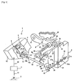
- FIG. 1 shows a range change apparatus 1 according to this embodiment as a typical vehicle range change apparatus.
- the figure schematically shows arrangements of the range change apparatus 1, a detent mechanism 7, a parking mechanism 8, and a valve body 9.
- First through sixth embodiments will be described as embodiments of the present invention.
- the range change apparatus 1 will be referred simply as the “range change apparatus 1" when portions commonly found in each of these six embodiments are to be described and as “range change apparatus 1 1 to 1 6 " when a specific one is to be described.
- the range change apparatus 1 is arranged so as to be mounted in an automatic transmission (for example, a multi-stage automatic transmission or a continuously variable transmission (CVT)) mounted in, for example, a vehicle.
- the range change apparatus 1 includes control means 3, a motor 4, a conversion mechanism (drive mechanism) 5, an arm member (rotary engagement member, drive mechanism) 6, and a range position detection sensor (detection unit) 11.
- the control means 3 generates a control signal S2 based on a shift signal (electric signal) S1 from a shift lever (range selector device) 2 with which a driver selects a shift range.
- the motor 4 is controlled by the control signal S2 from the control means 3.
- the conversion mechanism 5 converts rotary motion of the motor 4 into linear motion.
- the arm member 6 converts the linear motion converted by the conversion mechanism 5 into rocking motion.
- the range position detection sensor 11 detects the position of a spool 21 of a manual valve 20 to be described later by detecting the rotation angle of a manual shaft (range change shaft) 18 that is rotatably driven by the arm member 6.
- the motor 4, the conversion mechanism 5, the arm member 6, and the range position detection sensor 11 are accommodated in a single case (case member) 10.
- the automatic transmission roughly includes the hydraulic control unit (valve body) 9 for hydraulically controlling a speed change mechanism (not shown), the parking mechanism 8, and the detent mechanism 7.
- the detent mechanism 7 and the manual shaft 18 connected thereto are disposed on an outside of a case (not shown) of the automatic transmission.
- the spool 21 is disposed inside the valve body 9 of the automatic transmission and the parking mechanism 8 is accommodated in the case (not shown) of the automatic transmission.
- the shift lever 2 is marked with shift ranges (not shown) of a P (parking) range, an R (reverse) range, an N (neutral) range, and a D (drive) range of the automatic transmission.
- the driver directly operates the shift lever 2 to select one of the above mentioned shift ranges.
- the shift signal S 1 corresponding to the selected range is then generated.
- any range selector device other than the shift lever 2 may be used, as long as such range selector device can reflect the intention of the driver, specifically, can generate a shift signal S1 corresponding to the shift range selected by the driver.
- a shift button, a shift switch, or a voice input unit may be used.
- the control means 3 generates the control signal S2 based on the shift signal S1 generated by the shift lever 2 and uses the control signal S2 to drivingly control rotation of the motor 4 to be described later. Further, the control means 3 receives an input of a detection signal from the range position detection sensor 11 (to be described later) that detects the position of the spool 21 to be described later. Based on the detection signal, the control means 3 drivingly controls the direction and start/stop timing of rotation of the motor 4. As such, the control means 3 changes the shift range by controlling the operation of the spool 21 using the motor 4 based on the shift signal S 1 from the shift lever 2; specifically, the control means 3 is a control unit for controlling a so-called shift-by-wire system (SBW). Further, although FIG. 1 shows that the control means 3 is disposed outside the case 10, the control means 3 may be disposed on an inside of the case 10.
- SBW shift-by-wire system
- the detent mechanism 7 includes a detent lever 26, a detent spring 27, and a roller 28.
- the detent lever 26 is a plate-like member having a bearing portion 30 into which the manual shaft 18 is fitted.
- the detent lever 26 is rockably supported by the case of the automatic transmission (not shown) via the manual shaft 18.
- the detent lever 26 has one end portion (an end portion on the downward side in FIG. 1 ) in which an oblong slot 31 is drilled. A hook 25 at a leading end of a connection shaft 24 connected to the spool 21 is engaged in this slot 31.
- the spool 21 is a spool of the manual valve 20 disposed inside the valve body 9 and includes lands 21a, 21b, 21c in sequence, for example, from the left in the figure.
- the spool 21 is supported axially (in the direction of arrows A1-A2) movably. By axially moving, the spool 21 changes an oil path in the valve body 9 to set a predetermined shift range. Specifically, the spool 21 can move to a P position corresponding to the P range, an R position corresponding to the R range, an N position corresponding to the N range, and a D position corresponding to the D range.
- a leading end portion (an end portion on the upward side in FIG. 1 ) of the detent lever 26 includes range grooves a, c, e, g in sequence from the left as four change regions arranged in sequence from the left in the figure.
- Protrusions b, d, f are formed between each pair of the range grooves a, c, e, g.
- the range grooves a, c, e, g roughly correspond, in sequence, to the P position, the R position, the N position, and the D position of the above-described spool 21.
- the term "roughly" means that each of the range grooves a, c, e, g has a region with a width (change region).
- the detent spring 27 is formed from a substantially long plate-like member. As shown in FIG. 1 , the detent spring 27 has a proximal end portion 32 fixed to the valve body 9 and a distal end including bifurcated ends 33 formed therein. The roller 28 is rotatably supported between the bifurcated ends 33.
- the detent spring 27 generally acts as a flat spring, pressing the roller 28 that is rotatably disposed at the distal end thereof against a slope surface of each of the range grooves a, c, e, g of the detent lever 26, so that the detent lever 26 can be positioned and held in position accurately.
- the spool 21 is accurately controlled by accurately controlling the rotation angle of the manual shaft 18, instead of directly controlling the position of the spool 21, based on the arrangement in which the rocking motion of the detent lever 26 and the moving motion of the spool 21 in the direction of the arrows A1-A2 are operatively connected with each other; specifically, the rotation position of the manual shaft 18 corresponds one-to-one to the position of the spool 21.
- the parking mechanism 8 includes a parking rod 34, a wedge 35, a spring 37, a support 38, and a parking pole 40.
- the parking rod 34 has a proximal end side that is bent into an L-shape and engaged with the above-described detent lever 26.
- the wedge 35 with a conical shape is loose-fitted in a distal end side of the parking rod 34 and is movable.
- the spring 37 is connected to a flange portion 36 fixed to the parking rod 34 and to the wedge 35.
- the support 38 is disposed downwardly of the distal end side of the parking rod 34.
- the parking pole 40 is rockable and the wedge 35 is inserted between the support 38 and the parking pole 40.
- the parking pole 40 is disposed so as to be substantially vertically rockable about an axis 41 on a proximal end side thereof.
- the parking pole 40 has a pawl 43 disposed on an upper side thereof in a protruding condition.
- the pawl 43 is engageable with a parking gear 42 fixed to an output shaft (not shown) of the automatic transmission.
- Shift range change operations will next be briefly described using the change from the P range to the R range as an example.
- the roller 28 of the detent mechanism 7 is disposed in the range groove a shown in FIG. 1 .
- the shift signal S 1 corresponding to this is input to the control means 3.
- This causes the control means 3 to energize the motor 4 of the range change apparatus 1 to be described in detail later, so that the detent lever 26 rotates in the counterclockwise direction in FIG. 1 via the manual shaft 18 and the spool 21 moves in the direction of the arrow A 1.
- the control means 3 stops the rotation of the motor 4. This causes the roller 28 to move out of the range groove a, ride over the protrusion b, and enter the range groove c. With the motor 4 deenergized, the detent lever 26 is rotated by an urging force of the roller 28 based on an elastic force of the detent spring 27. Through this rotation, the roller 28 is accurately positioned and held in position in the range groove c. This results in the spool 21 that has been disposed at the P position being accurately disposed at the R position. Other shift range change operations are substantially the same as above and description for the same will be omitted.
- the case 10 includes a case main body 10a and a cover 10b.
- the case main body 10a is fixed to the automatic transmission.
- the cover 10b covers the case main body 10a from an upward direction.
- FIG. 2 shows a condition in which the cover 10b is removed.
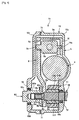
- FIG. 3 is a cross-sectional view taken along line A-A of FIG. 2 .
- the motor 4 includes a cylindrical main body 4a, an output shaft 4b, and a motor terminal portion 4c.
- the output shaft 4b is disposed at one end side of the main body 4a in a protruding condition.
- the motor terminal portion 4c is disposed at the other end side of the main body 4a. Power is supplied to, and the control signal S2 from the control means 3 is input to, the motor terminal portion 4c.
- a DC motor having a permanent magnet for example, is used as the motor 4 and the control means 3 controls the direction, time, and timing of rotation of the motor 4.
- a transmission gear 12a is fixed to the output shaft 4b of the motor 4 so as to be integrally rotatable therewith.
- the transmission gear 12a meshes with a transmission gear 12b.
- the transmission gear 12b is fitted to a transmission shaft 13 that is fixed to the case 10 so as to be rotatable thereabout and has a larger outside diameter than the transmission gear 12a.
- a transmission gear 12c having a smaller outside diameter than the transmission gear 12b is integrally fixed to the transmission gear 12b.
- the transmission gear 12c meshes with a transmission gear 12d having a larger outside diameter than the transmission gear 12c.
- the transmission gear 12d is fixed to a screw shaft 5a of the conversion mechanism 5 to be described later so as to be rotatable integrally therewith. Consequently, rotation of the output shaft 4b of the motor 4 undergoes speed reduction by a transmission gear train (drive mechanism) 12 including these transmission gears 12a, 12b, 12c, 12d before being transmitted to the screw shaft 5a.
- the conversion mechanism 5 incorporates a slide screw according to this embodiment.
- the slide screw as the conversion mechanism 5 includes, as shown in FIG. 2 , the screw shaft 5a and a nut member 5b.
- the screw shaft 5a is rotatably driven by the motor 4.
- the nut member 5b is engaged axially movably with the screw shaft 5a.
- the screw shaft 5a is rotatably supported by the case 10 via a bearing 5d fixed by a bracket relative to the case 10.
- the nut member 5b is formed substantially into a rectangular parallelepiped including a guide rail 5e formed along an axial direction on a back surface side (right side in FIG. 3 ).
- the guide rail 5e is loose-fitted in a guide groove 14a of a guide member 14 that is fixedly disposed on the inside of the case main body 10a and placed in parallel with the screw shaft 5a.
- the nut member 5b is guided axially so as to be incapable of rotation as the screw shaft 5a rotates.
- the nut member 5b includes a protrusion 5c formed at the front side thereof (left side in FIG. 3 ).
- the arm member 6 to be described later is engaged with the protrusion 5c.
- the conversion mechanism 5 is structured so as to be capable of converting rotary motion into linear motion (linear drive).
- the arm member 6 includes a slot-like opening 6a formed at one end thereof.
- the protrusion 5c of the nut member 5b is engaged in the opening 6a.
- the arm member 6 includes through holes 6b, 6c formed at the other end thereof as shown in FIG. 3 .
- the manual shaft 18 has a leading end portion fitted relatively unrotatably into the through holes 6b, 6c.
- the manual shaft 18 includes a two-chamfered-face portion 18a and a taper portion (end portion) 18b.
- the two-chamfered-face portion 18a has two chamfered faces, each extending in parallel with each other, formed at the leading end portion of the manual shaft 18.
- the taper portion 18b is formed to be thinner than the two-chamfered-face portion 18a. The difference in diameter between these two portions results in a step portion 18c being formed.
- an external thread 18d is formed on an outer peripheral side of the taper portion 18b excluding the two chamfered faces (see FIGS. 1 and 6 ).
- the through hole 6c has a larger diameter than the through hole 6b so as to match the profile of the manual shaft 18.
- the difference in diameter between these through holes results in an abutment portion 6e being formed in the arm member 6.
- the two-chamfered-face portion 18a fits into the through hole 6c
- the taper portion 18b fits into the through hole 6b
- the step portion 18c abuts on the abutment portion 6e.
- a seal ring 72 is disposed between the manual shaft 18 and the main body 10a of the case 10. Coupled with a seal member 71 disposed between the main body 10a and the cover 10b in the case 10, the seal ring 72 constitutes a hermetically sealed structure for the case 10, thus preventing entry of foreign matter and achieving waterproofness.
- the range position detection sensor 11 is formed from a potentiometer disposed so as to surround the manual shaft 18 disposed penetratingly.
- the range position detection sensor 11 includes a rotor 11a and an angle sensor 11b.
- the rotor 11a has a permanent magnet mounted internally therein.
- the angle sensor 11b rotatably supports the rotor 11a and has a hall element mounted internally therein.
- the angle sensor 11b detects the angle of the rotor 11a.
- the rotor 11a includes a through hole 11f formed so as to match the profile of the two-chamfered-face portion 18a of the manual shaft 18 at a substantially center position thereof.
- the through hole 11f is formed from, for example, a resin material that is formed to be slightly smaller in size than the two-chamfered-face portion 18a.
- the two-chamfered-face portion 18a is press-fitted into the through hole 11f. This results in the rotor 11a being fitted into an outer peripheral portion of the manual shaft 18, disposed unrotatably relative to the manual shaft 18.
- the range position detection sensor 11 then accurately detects the rotation angle of the manual shaft 18 without allowing, for example, play to intervene.
- the range position detection sensor 11 includes a sensor terminal portion 11e for outputting voltage corresponding to the rotation angle of the manual shaft 18. Specifically, the sensor terminal portion 11e outputs a signal indicative of the angle of the manual shaft 18 to the control means 3.
- the control means 3 uses this angle signal for feedback control of the amount of driving rotation of the motor 4. Specifically, drive/stop of the motor 4 is controlled according to the detection result of the angle of the manual shaft 18 by the range position detection sensor 11. Since the arm member 6 and the manual shaft 18 are fastened together as described above, the drive/stop of the motor 4 is controlled without involving, for example, the manual shaft being driven via play; specifically, the range change is controlled accurately. Note that the embodiment has been described for the arrangement in which the range position detection sensor 11 is formed of a potentiometer. However, the arrangement is not limited to this and any type of sensor may be used as long as such a sensor can output an electric signal corresponding to the rotation angle of the manual shaft 18.
- the cover 10b of the case 10 includes an insertion hole (fastening enabling unit) 10c formed at a position on an extension extended coaxially from the manual shaft 18.
- a tool for tightening the nut 50 for example, hexagonal wrench
- the insertion hole 10c has internal threads formed therein, while the lid member 51 has external threads (external thread portion) formed thereon.
- the lid member 51 is threaded into the insertion hole 10c.
- the seal ring 73 hermetically seals a portion between the case 10 and the lid member 51.
- the seal ring may be separate from the lid member and embedded into a groove that may be formed in the case.
- the lid member 51 makes the nut 50 invisible with the vehicle range change apparatus 1 1 mounted on the manual shaft 18, so that it is unknown how the nut 50 achieves fixing.
- an antitheft effect can be achieved against an act of, for example, stealing a vehicle by, for example, rotating the manual shaft 18 and disengaging the parking gear.
- the lid member 51 and the nut 50 are separate from each other. As compared, for example, with an arrangement in which a nut 60 plugs the insertion hole (see a second embodiment to be described later), it takes time to cancel the fastening of the nut 50, yielding an antitheft effect.
- the insertion hole 10c is plugged by threadedly engaging the lid member 51 into the insertion hole 10c.
- a cap-shaped member formed of, for example, a resin material may be fixed to the insertion hole 10c using, for example, an adhesive.
- a second embodiment which is the first embodiment partly modified, will be described below with reference to FIG. 4 .
- Similar members as those of the above-described first embodiment will be identified with the same reference numerals and descriptions therefor will be omitted.
- a range change apparatus 1 2 includes a nut (fastening unit) 60 that is the nut 50 in the first embodiment (see FIG. 3 ) with a modified shape.
- the nut 60 is formed from a so-called cap nut with an internal thread 60a opening in one direction only.
- a cover 10b of a case 10 includes a through hole (fastening enabling unit) 10d.
- the nut 60 is thereby disposed in an extended condition so as to protrude from the through hole 10d.
- a substantially axially central portion of the nut 60 in particular, is formed into an outer peripheral cylindrical portion (fastening enabling unit) 60b having a cylindrically formed outer peripheral side.
- the outer peripheral cylindrical portion 60b is extended up to the through hole 10d in the cover 10b.
- a distal end side of the nut 60 relative to the outer peripheral cylindrical portion 60b, specifically, a portion protruding to the outside from the cover 10 includes a six-chamfered-face portion (fastening enabling unit, torque receiving portion) 60c formed thereon that has six chamfered faces and receives rotating torque of, for example, a hexagonal wrench, spanner, or other tool.
- a seal ring 75 is disposed on a circumference of the through hole 10d between the outer peripheral cylindrical portion 60b and the through hole 10d in the cover 10b. The seal ring 75 seals the nut 60 rotatably, while maintaining a hermetic seal.
- the manual shaft 18 and an arm member 6 can be fastened together by simply tightening the six-chamfered-face portion 60c of the nut 60 with a tool at an outside of the case 10.
- fastening inside the case 10 can be made in an assembled state of the range change apparatus 1 2 without disassembling the case 10. Processes involved in mounting the range change apparatus 1 2 on the manual shaft 18 can therefore be simplified.
- good sealing performance of the case 10 can be achieved and entry of foreign matter can be prevented.
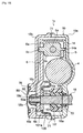
- a third embodiment which is the first embodiment partly modified, will be described below with reference to FIGS. 5 and 6 . Note that similar members as those of the above-described first embodiment will be identified with the same reference numerals and descriptions therefor will be omitted.
- a range change apparatus 1 3 represents an improvement on the relationship between the aim member 6 and the range position detection sensor 11 which are away from each other according to the first embodiment (see FIG. 3 ).
- a rotor 11a of the range position detection sensor 11 includes a protrusion 11c that protrudes toward the side of the arm member 6.
- the protrusion 11c is formed into a two-chamfered-face portion.
- the arm member 6, on the other hand, includes a through hole 6d having a shape that matches the profile of the protrusion 11c. The protrusion 11c and the through hole 6d thereby each form a fit portion that is mutually fitted together.
- the protrusion 11c has an end face 11d that is formed to be flush with a step portion 18c of the manual shaft 18 (the protrusion 11c may be slightly shorter).
- the rotor 11a is thereby structured not to impede fastening when the arm member 6 and the manual shaft 18 are fastened together by tightening a nut 50.
- the arm member 6 and the rotor 11a are fitted together when the range change apparatus 1 3 is assembled. Consequently, when the range change apparatus 1 3 is to be mounted on the manual shaft 18 disposed in the automatic transmission, a through hole 11f in the rotor 11a and a through hole 6b in the arm member 6 are lined up on the same axis without being deviated from each other.
- the manual shaft 18 can therefore be inserted easily; specifically, mounting processes can be simplified.
- the rotor 11a is prevented from being turned through 180 degrees during, for example, transportation. Specifically, when the manual shaft 18 is inserted, the rotor 11a can be prevented from being mounted in an inverted position.
- a range change apparatus 1 4 according to a fourth embodiment is the range change apparatus 1 2 according to the second embodiment including a fit portion between the arm member 6 and the rotor 11a in the same manner as in the third embodiment. This results in the same effect as in the third embodiment being achieved, in addition to those of the range change apparatus 1 2 according to the second embodiment.
- a fifth embodiment which is the first embodiment partly modified, will be described below with reference to FIGS. 8 and 9 . Note that similar members as those of the above-described first embodiment will be identified with the same reference numerals and descriptions therefor will be omitted.
- the lid member 51 in the first embodiment is changed to a plate cover (covering member, plate-like member) 80.
- the fastening portion between the manual shaft 18, the arm member 6, and the range position detection sensor 11 using the nut 50 is changed.
- the arm member 6 is directly fastened to the manual shaft 18 using the nut 50.
- the arm member 6 is fastened with the nut 50 to the manual shaft 18 via a washer member 81 and the washer member 81 is connected to a rotor 11a of the range position detection sensor 11.
- a through hole 6b formed in the arm member 6 is formed to match the profile of a two-chamfered-face portion 18a of the manual shaft 18 and the two-chamfered-face portion 18a is fitted in the through hole 6b.
- the arm member 6 is rotated to rotate the manual shaft 18 as the above-described nut member 5b moves axially along the screw shaft 5a.
- the washer member 81 is structured to include a washer portion 81a and two leg portions 81b, 81b.
- the washer portion 81a includes a through hole 81c formed therein through which a taper portion 18b of the manual shaft 18 penetrates. Specifically, a step portion 18c of the manual shaft 18 abuts on the washer portion 81a and an internal thread 50a of the nut 50 is threadedly tightened with an external thread 18d of the taper portion 18b, so that the washer member 81 is fastened to the manual shaft 18.
- the arm member 6 includes through holes (not shown) through which the leg portions 81b, 81b penetrate.
- the leg portions 81b, 81b are fitted so as to clamp the rotor 11a of the range position detection sensor 11. This integrally fastens together the manual shaft 18, the rotor 11a of the range position detection sensor 11, the washer member 81, and the nut 50.
- the arm member 6 is loose-fitted with a gap from the rotor 11a of the range position detection sensor 11 and the washer portion 81a of the washer member 81 relative to the axial direction of the manual shaft 18.
- the arm member 6 is also relatively unrotatably engaged relative to the direction of rotation of the manual shaft 18 with the through hole 6b fitted with the profile of the two-chamfered-face portion 18a.
- a cover 10b of a case 10 includes an insertion hole (fastening enabling unit) 10e formed at a position on an extension extended coaxially from the manual shaft 18.
- a tool for tightening the nut 50 (for example, hexagonal wrench) can be inserted into the insertion hole 10e.
- the plate cover 80 formed through, for example, pressworking is fixed on the outside (left side in FIG. 8 ) of the insertion hole 10e in a tight contact condition using screws 91, 91 (see FIG. 9 ).
- a plurality of (at six places) screws 90 shown in FIG. 9 fastens a case main body 10a with the cover 10b.
- a seal ring 76 is disposed on the outer peripheral side of the insertion hole 10e in the cover 10b of the case 10, sealing between the plate cover 80 and the cover 10b. This achieves good sealing performance of the case 10 without having to process portions of tight contact between the plate cover 80 and the case 10 to close tolerances. Specifically, this enables forming of the plate cover 80 through pressworking, achieving cost reduction.
- fastening of the manual shaft 18 with the arm member 6 using the nut 50 can be done inside the case 10 through a simple procedure of removing the plate cover 80 and, after fastening, mounting the plate cover 80 results in good sealing performance of the case 10.
- the member for covering the insertion hole 10e is formed into a plate shape. This contributes to reduction in size in a thickness direction (right-left direction in FIG. 8 ) of the range change apparatus 1 5 .
- the plate cover 80 can be formed through, for example, pressworking, so that cost reduction can be achieved.
- the washer member 81 and the rotor 11a are fitted together by the leg portions 81b, 81b via the arm member 6 when the range change apparatus 1 5 is assembled. Consequently, when the range change apparatus 1 5 is to be mounted on the manual shaft 18 disposed in the automatic transmission, a through hole 11f in the rotor 11a, the through hole 6b in the arm member 6, and the through hole 81c in the washer member 81 are lined up on the same axis without being deviated from each other.
- the manual shaft 18 can therefore be inserted easily; specifically, mounting processes can be simplified.
- the rotor 11a is prevented from being turned through 180 degrees during, for example, transportation. Specifically, when the manual shaft 18 is inserted, the rotor 11a can be prevented from being mounted in an inverted position.
- the plate cover 80 makes the nut 50 invisible with the vehicle range change apparatus 1 5 mounted on the manual shaft 18, so that it is unknown how the nut 50 achieves fixing. Therefore, an antitheft effect can be achieved against an act of, for example, stealing a vehicle by, for example, rotating the manual shaft 18 and disengaging the parking gear.
- the plate cover 80 and the nut 50 are separate from each other. As compared, for example, with the arrangement in which the nut 60 plugs the insertion hole (see, for example, the second embodiment), it takes time to cancel the fastening of the nut 50, yielding an antitheft effect.
- a sixth embodiment which is the first and fifth embodiments partly modified, will be described below with reference to FIGS. 10 and 11 . Note that similar members as those of the above-described first and fifth embodiments will be identified with the same reference numerals and descriptions therefor will be omitted.
- the lid member 51 in the first embodiment is changed to a plate cover (plate-like member) 80, as in the fifth embodiment.
- the fastening portion between the manual shaft 18 and the aim member 6 using the nut 50 is changed and the manual shaft 18 is supported by a support member 100.
- the support member 100 is disposed between a case main body 10a and a cover 10b.
- the support member 100 has an end portion 100b clamped between a clamp portion 10f of the case main body 10a and a clamp portion (not shown) of the cover 10b.
- the support member 100 is fixed to the case main body 10a using, for example, two screws 92, 92.
- the support member 100 includes, as shown in FIGS. 10 and 11 , a circular support hole 100a formed at a center of a protruded portion thereof.
- a disc-like member 101 formed into a disc shape is disposed in the support hole 100a.
- the disc-like member 101 has an outer peripheral surface 101a formed into a circle and is supported slidably by the support hole 100a.
- the disc-like member 101 has a side surface 101b fixed to the arm member 6.
- the support member 100 rotatably supports the arm member 6 via the disc-like member 101.
- the arm member 6 includes a through hole 6b formed therein so as to be fitted with a taper portion 18b of the manual shaft 18.
- the disc-like member 101 includes a through hole 101c formed therein so as to be fitted with a two-chamfered-face portion 18a.
- a step portion 18c of the manual shaft 18 abuts on the arm member 6 and an internal thread 50a of the nut 50 is threadedly tightened with an external thread 18d of the taper portion 18b, so that the arm member 6 and the disc-like member 101 fixed thereto are fastened to the manual shaft 18. Consequently, the manual shaft 18 is fastened to the arm member 6 with the support member 100 rotatably supporting the disc-like member 101 and the arm member 6, so that the support member 100 rotatably supports the manual shaft 18 via the disc-like member 101 and the arm member 6.
- the support member 100 rotatably supports the manual shaft 18 via the disc-like member 101 and the arm member 6.
- the support member 100 and the disc-like member 101 can receive that force, so that support accuracy of the arm member 6 in a tilt direction can be improved.
- the first through sixth embodiments described heretofore have been described for the arrangement in which the vehicle range change apparatus 1 is mounted in the automatic transmission. Understandably, the arrangement is not limited only this and the range change apparatus may be used, for example, in a hybrid vehicle in which the apparatus is used as a parking mechanism change apparatus without changing hydraulic ranges.
- the range change apparatus can be used for changing shift ranges through electric commands in, for example, passenger vehicles, trucks, buses, and agricultural machines.
- the apparatus is particularly suitable for use in a range change apparatus that is required to be easily mounted on a range change shaft included in the vehicle and to prevent entry of foreign matter.
Landscapes
- Engineering & Computer Science (AREA)
- General Engineering & Computer Science (AREA)
- Mechanical Engineering (AREA)
- Gear-Shifting Mechanisms (AREA)
Claims (2)
- Appareil (1) de changement de gamme de véhicule qui comprend :un moteur (4) ;un mécanisme (5, 6, 12) d'entraînement, le mécanisme (5, 6, 12) d'entraînement comportant :un mécanisme (5) de conversion permettant de convertir un mouvement rotatif du moteur (4) en un mouvement linéaire ; etun élément (6) de prise en rotation permettant de convertir le mouvement linéaire converti par le mécanisme (5) de conversion en un mouvement de balancement, le mécanisme (5, 6, 12) d'entraînement permettant de transmettre ainsi la rotation d'entraînement du moteur (4)une unité (11) de détection traversée par un arbre (18) de changement de gamme qui est entraîné en rotation par l'élément (6) de prise en rotation, l'unité (11) de détection permettant de détecter un angle de rotation de l'arbre (18) de changement de gamme ; etun boîtier (10) permettant de faire sceller hermétiquement au moins l'élément (6) de prise en rotation et l'unité (11) de détection, le moteur (4) étant commandé à entraînement sur la base d'une gamme de décalage sélectionnée par un dispositif (2) de sélection de gamme et sur un résultat de détection de l'unité (11) de détection, l'appareil (1) de changement de gamme de véhicule comprenant :une unité (60) de fixation permettant de fixer à l'intérieur du boîtier (10) une partie (18b) d'extrémité de l'arbre (18) de changement de gamme qui pénètre à travers, et avance à partir de l'unité (11) de détection et de l'élément (6) de prise en rotation ;caractérisé parune unité (10d, 75) de déclenchement de fixation permettant de faire la fixation à l'intérieur du boîtier (10) en utilisant l'unité (60) de fixation lorsque l'élément (6) de prise en rotation et l'arbre (18) de changement de gamme sont attachés en utilisant l'unité de fixation (50, 60) de l'appareil (1) de changement de gamme de véhicule dans un état monté, dans lequell'unité (10d, 75) de déclenchement de fixation comprend un trou (10d) débouchant formé dans le boîtier (10) et un élément (75) de joint d'étanchéité disposé sur une circonférence du trou (10d) débouchant ; etl'unité (60) de fixation comprend un écrou qui comporte : une partie (60b) cylindrique périphérique extérieure s'engageant par un vissage de filetage (18d) extérieur formé sur la partie d'extrémité (18b) de l'arbre (18) de changement de gamme, s'étendant jusqu'au trou (10d) débouchant, et scellée à une partie de celui-ci relative au trou (10d) débouchant par l'élément (75) de joint d'étanchéité, et une partie (60c) de réception de couple permettant de recevoir le couple de rotation d'un outil à l'extérieur du boîtier (10).
- Appareil (1) de changement de gamme de véhicule selon la revendication 1, caractérisé en ce que
l'unité (11) de détection comporte : un rotor (11a) monté sur l'arbre (18) de changement de gamme et pouvant tourner intégralement avec celui-ci; et un capteur (11b) d'angle permettant de détecter un angle de rotation du rotor (11a), et
l'appareil (1) de changement de gamme de véhicule comporte une partie (6d, 11c) ajustable dans laquelle l'élément (6) de prise en rotation du mécanisme (5, 6, 12) d'entraînement et le rotor (11a) sont montés de manière non rotative.
Applications Claiming Priority (2)
| Application Number | Priority Date | Filing Date | Title |
|---|---|---|---|
| JP2008088307 | 2008-03-28 | ||
| PCT/JP2009/001409 WO2009119115A1 (fr) | 2008-03-28 | 2009-03-27 | Appareil de changement de gamme de véhicule |
Publications (3)
| Publication Number | Publication Date |
|---|---|
| EP2235403A1 EP2235403A1 (fr) | 2010-10-06 |
| EP2235403A4 EP2235403A4 (fr) | 2011-06-22 |
| EP2235403B1 true EP2235403B1 (fr) | 2012-08-29 |
Family
ID=41113326
Family Applications (1)
| Application Number | Title | Priority Date | Filing Date |
|---|---|---|---|
| EP09725145A Not-in-force EP2235403B1 (fr) | 2008-03-28 | 2009-03-27 | Appareil de changement de gamme de vehicule |
Country Status (3)
| Country | Link |
|---|---|
| EP (1) | EP2235403B1 (fr) |
| JP (1) | JP5254345B2 (fr) |
| WO (1) | WO2009119115A1 (fr) |
Families Citing this family (3)
| Publication number | Priority date | Publication date | Assignee | Title |
|---|---|---|---|---|
| DE102013101503A1 (de) * | 2013-02-14 | 2014-08-14 | Knorr-Bremse Systeme für Nutzfahrzeuge GmbH | Fahrzeuggetriebe, Verfahren und Sensorvorrichtung zum Erfassen einer Schaltstellung eines Fahrzeuggetriebes |
| JP6113251B1 (ja) * | 2015-11-11 | 2017-04-12 | 三菱電機株式会社 | レンジ切り替え装置 |
| JP6801392B2 (ja) * | 2016-11-18 | 2020-12-16 | アイシン精機株式会社 | シフトバイワイヤ式自動変速機のアクチュエータ |
Family Cites Families (6)
| Publication number | Priority date | Publication date | Assignee | Title |
|---|---|---|---|---|
| JPH0381454U (fr) * | 1989-12-11 | 1991-08-20 | ||
| JPH07299539A (ja) * | 1994-05-09 | 1995-11-14 | Pop Rivet Fastener Kk | 締結工具における締結具破断片回収装置 |
| JP3890954B2 (ja) * | 2001-10-31 | 2007-03-07 | アイシン・エィ・ダブリュ株式会社 | 自動変速機のシフト検出装置 |
| JP2003254434A (ja) | 2002-02-28 | 2003-09-10 | Aisin Aw Co Ltd | 車輌のレンジ切替え装置 |
| JP4109482B2 (ja) * | 2002-04-12 | 2008-07-02 | マスプロ電工株式会社 | 電子機器における蓋体の繋ぎ止め構造 |
| JP2005207570A (ja) | 2003-04-18 | 2005-08-04 | Aisin Aw Co Ltd | 車輌のレンジ切換え装置 |
-
2009
- 2009-03-27 WO PCT/JP2009/001409 patent/WO2009119115A1/fr active Application Filing
- 2009-03-27 JP JP2010528074A patent/JP5254345B2/ja not_active Expired - Fee Related
- 2009-03-27 EP EP09725145A patent/EP2235403B1/fr not_active Not-in-force
Also Published As
| Publication number | Publication date |
|---|---|
| EP2235403A4 (fr) | 2011-06-22 |
| EP2235403A1 (fr) | 2010-10-06 |
| JP2011510227A (ja) | 2011-03-31 |
| JP5254345B2 (ja) | 2013-08-07 |
| WO2009119115A1 (fr) | 2009-10-01 |
Similar Documents
| Publication | Publication Date | Title |
|---|---|---|
| US6550351B1 (en) | Transmission range selector system | |
| JP4433022B2 (ja) | 電動モータ | |
| AU727643B2 (en) | Electrically controlled clamping device for a system for adjusting the position of one member relative to another member | |
| US7819041B2 (en) | Transmission ratio variable device and steering gear | |
| US20130160597A1 (en) | Steering apparatus | |
| US20120324965A1 (en) | Steering apparatus | |
| EP3324081B1 (fr) | Actionneur de changement de vitesse pour une transmission automatique de type shift by wire | |
| WO2012081283A1 (fr) | Dispositif de verrouillage électrique de véhicule | |
| JP2004243947A (ja) | ウォームシャフト可動量調整方法及び電動パワーステアリング装置用減速機 | |
| EP2235403B1 (fr) | Appareil de changement de gamme de vehicule | |
| US8146454B2 (en) | Vehicle range switching device | |
| EP3339689B1 (fr) | Dispositif de changement de vitesse | |
| KR101575371B1 (ko) | 차량의 쉬프트 바이 와이어 변속 조작장치 | |
| JP4840092B2 (ja) | シフトバイワイヤ式レンジ切換え装置 | |
| JP2006234016A (ja) | シフトレバー装置 | |
| JP2003185013A (ja) | 車両用変速制御装置 | |
| JP2007071370A (ja) | 車両制御装置 | |
| KR100585997B1 (ko) | 차량용 미러 조정기구의 클러치 구조 | |
| JP2000326754A (ja) | 自動車用アクセルペダル装置 | |
| JP5004157B2 (ja) | 操作軸の接続部材、およびこの接続部材を備えた遠隔操作装置 | |
| JP2005273898A (ja) | アシスト装置および操作ケーブルユニット | |
| WO2020044972A1 (fr) | Dispositif de changement de vitesse | |
| JP4992429B2 (ja) | 位置検出装置 | |
| KR100532934B1 (ko) | 차량용 미러 조정기구의 클러치 구조 | |
| JP2020133697A (ja) | レンジ切換装置及びパーキング機構 |
Legal Events
| Date | Code | Title | Description |
|---|---|---|---|
| PUAI | Public reference made under article 153(3) epc to a published international application that has entered the european phase |
Free format text: ORIGINAL CODE: 0009012 |
|
| 17P | Request for examination filed |
Effective date: 20100722 |
|
| AK | Designated contracting states |
Kind code of ref document: A1 Designated state(s): AT BE BG CH CY CZ DE DK EE ES FI FR GB GR HR HU IE IS IT LI LT LU LV MC MK MT NL NO PL PT RO SE SI SK TR |
|
| AX | Request for extension of the european patent |
Extension state: AL BA RS |
|
| A4 | Supplementary search report drawn up and despatched |
Effective date: 20110524 |
|
| DAX | Request for extension of the european patent (deleted) | ||
| REG | Reference to a national code |
Ref country code: DE Ref legal event code: R079 Ref document number: 602009009304 Country of ref document: DE Free format text: PREVIOUS MAIN CLASS: F16H0061280000 Ipc: F16H0061320000 |
|
| GRAP | Despatch of communication of intention to grant a patent |
Free format text: ORIGINAL CODE: EPIDOSNIGR1 |
|
| RIC1 | Information provided on ipc code assigned before grant |
Ipc: F16H 57/029 20120101ALI20120130BHEP Ipc: F16H 61/32 20060101AFI20120130BHEP |
|
| GRAS | Grant fee paid |
Free format text: ORIGINAL CODE: EPIDOSNIGR3 |
|
| GRAA | (expected) grant |
Free format text: ORIGINAL CODE: 0009210 |
|
| AK | Designated contracting states |
Kind code of ref document: B1 Designated state(s): AT BE BG CH CY CZ DE DK EE ES FI FR GB GR HR HU IE IS IT LI LT LU LV MC MK MT NL NO PL PT RO SE SI SK TR |
|
| REG | Reference to a national code |
Ref country code: GB Ref legal event code: FG4D |
|
| REG | Reference to a national code |
Ref country code: CH Ref legal event code: EP |
|
| REG | Reference to a national code |
Ref country code: AT Ref legal event code: REF Ref document number: 573251 Country of ref document: AT Kind code of ref document: T Effective date: 20120915 |
|
| REG | Reference to a national code |
Ref country code: IE Ref legal event code: FG4D |
|
| REG | Reference to a national code |
Ref country code: DE Ref legal event code: R096 Ref document number: 602009009304 Country of ref document: DE Effective date: 20121025 |
|
| REG | Reference to a national code |
Ref country code: AT Ref legal event code: MK05 Ref document number: 573251 Country of ref document: AT Kind code of ref document: T Effective date: 20120829 |
|
| REG | Reference to a national code |
Ref country code: NL Ref legal event code: VDEP Effective date: 20120829 |
|
| REG | Reference to a national code |
Ref country code: LT Ref legal event code: MG4D Effective date: 20120829 |
|
| PG25 | Lapsed in a contracting state [announced via postgrant information from national office to epo] |
Ref country code: LT Free format text: LAPSE BECAUSE OF FAILURE TO SUBMIT A TRANSLATION OF THE DESCRIPTION OR TO PAY THE FEE WITHIN THE PRESCRIBED TIME-LIMIT Effective date: 20120829 Ref country code: HR Free format text: LAPSE BECAUSE OF FAILURE TO SUBMIT A TRANSLATION OF THE DESCRIPTION OR TO PAY THE FEE WITHIN THE PRESCRIBED TIME-LIMIT Effective date: 20120829 Ref country code: FI Free format text: LAPSE BECAUSE OF FAILURE TO SUBMIT A TRANSLATION OF THE DESCRIPTION OR TO PAY THE FEE WITHIN THE PRESCRIBED TIME-LIMIT Effective date: 20120829 Ref country code: IS Free format text: LAPSE BECAUSE OF FAILURE TO SUBMIT A TRANSLATION OF THE DESCRIPTION OR TO PAY THE FEE WITHIN THE PRESCRIBED TIME-LIMIT Effective date: 20121229 Ref country code: NO Free format text: LAPSE BECAUSE OF FAILURE TO SUBMIT A TRANSLATION OF THE DESCRIPTION OR TO PAY THE FEE WITHIN THE PRESCRIBED TIME-LIMIT Effective date: 20121129 Ref country code: AT Free format text: LAPSE BECAUSE OF FAILURE TO SUBMIT A TRANSLATION OF THE DESCRIPTION OR TO PAY THE FEE WITHIN THE PRESCRIBED TIME-LIMIT Effective date: 20120829 |
|
| PG25 | Lapsed in a contracting state [announced via postgrant information from national office to epo] |
Ref country code: LV Free format text: LAPSE BECAUSE OF FAILURE TO SUBMIT A TRANSLATION OF THE DESCRIPTION OR TO PAY THE FEE WITHIN THE PRESCRIBED TIME-LIMIT Effective date: 20120829 Ref country code: SI Free format text: LAPSE BECAUSE OF FAILURE TO SUBMIT A TRANSLATION OF THE DESCRIPTION OR TO PAY THE FEE WITHIN THE PRESCRIBED TIME-LIMIT Effective date: 20120829 Ref country code: PT Free format text: LAPSE BECAUSE OF FAILURE TO SUBMIT A TRANSLATION OF THE DESCRIPTION OR TO PAY THE FEE WITHIN THE PRESCRIBED TIME-LIMIT Effective date: 20121231 Ref country code: SE Free format text: LAPSE BECAUSE OF FAILURE TO SUBMIT A TRANSLATION OF THE DESCRIPTION OR TO PAY THE FEE WITHIN THE PRESCRIBED TIME-LIMIT Effective date: 20120829 Ref country code: BE Free format text: LAPSE BECAUSE OF FAILURE TO SUBMIT A TRANSLATION OF THE DESCRIPTION OR TO PAY THE FEE WITHIN THE PRESCRIBED TIME-LIMIT Effective date: 20120829 Ref country code: GR Free format text: LAPSE BECAUSE OF FAILURE TO SUBMIT A TRANSLATION OF THE DESCRIPTION OR TO PAY THE FEE WITHIN THE PRESCRIBED TIME-LIMIT Effective date: 20121130 |
|
| PG25 | Lapsed in a contracting state [announced via postgrant information from national office to epo] |
Ref country code: RO Free format text: LAPSE BECAUSE OF FAILURE TO SUBMIT A TRANSLATION OF THE DESCRIPTION OR TO PAY THE FEE WITHIN THE PRESCRIBED TIME-LIMIT Effective date: 20120829 Ref country code: EE Free format text: LAPSE BECAUSE OF FAILURE TO SUBMIT A TRANSLATION OF THE DESCRIPTION OR TO PAY THE FEE WITHIN THE PRESCRIBED TIME-LIMIT Effective date: 20120829 Ref country code: NL Free format text: LAPSE BECAUSE OF FAILURE TO SUBMIT A TRANSLATION OF THE DESCRIPTION OR TO PAY THE FEE WITHIN THE PRESCRIBED TIME-LIMIT Effective date: 20120829 Ref country code: DK Free format text: LAPSE BECAUSE OF FAILURE TO SUBMIT A TRANSLATION OF THE DESCRIPTION OR TO PAY THE FEE WITHIN THE PRESCRIBED TIME-LIMIT Effective date: 20120829 Ref country code: ES Free format text: LAPSE BECAUSE OF FAILURE TO SUBMIT A TRANSLATION OF THE DESCRIPTION OR TO PAY THE FEE WITHIN THE PRESCRIBED TIME-LIMIT Effective date: 20121210 Ref country code: CZ Free format text: LAPSE BECAUSE OF FAILURE TO SUBMIT A TRANSLATION OF THE DESCRIPTION OR TO PAY THE FEE WITHIN THE PRESCRIBED TIME-LIMIT Effective date: 20120829 |
|
| PGFP | Annual fee paid to national office [announced via postgrant information from national office to epo] |
Ref country code: DE Payment date: 20130320 Year of fee payment: 5 |
|
| PG25 | Lapsed in a contracting state [announced via postgrant information from national office to epo] |
Ref country code: IT Free format text: LAPSE BECAUSE OF FAILURE TO SUBMIT A TRANSLATION OF THE DESCRIPTION OR TO PAY THE FEE WITHIN THE PRESCRIBED TIME-LIMIT Effective date: 20120829 Ref country code: PL Free format text: LAPSE BECAUSE OF FAILURE TO SUBMIT A TRANSLATION OF THE DESCRIPTION OR TO PAY THE FEE WITHIN THE PRESCRIBED TIME-LIMIT Effective date: 20120829 Ref country code: SK Free format text: LAPSE BECAUSE OF FAILURE TO SUBMIT A TRANSLATION OF THE DESCRIPTION OR TO PAY THE FEE WITHIN THE PRESCRIBED TIME-LIMIT Effective date: 20120829 |
|
| PLBE | No opposition filed within time limit |
Free format text: ORIGINAL CODE: 0009261 |
|
| STAA | Information on the status of an ep patent application or granted ep patent |
Free format text: STATUS: NO OPPOSITION FILED WITHIN TIME LIMIT |
|
| PG25 | Lapsed in a contracting state [announced via postgrant information from national office to epo] |
Ref country code: BG Free format text: LAPSE BECAUSE OF FAILURE TO SUBMIT A TRANSLATION OF THE DESCRIPTION OR TO PAY THE FEE WITHIN THE PRESCRIBED TIME-LIMIT Effective date: 20121129 |
|
| 26N | No opposition filed |
Effective date: 20130530 |
|
| REG | Reference to a national code |
Ref country code: DE Ref legal event code: R097 Ref document number: 602009009304 Country of ref document: DE Effective date: 20130530 |
|
| PG25 | Lapsed in a contracting state [announced via postgrant information from national office to epo] |
Ref country code: MC Free format text: LAPSE BECAUSE OF NON-PAYMENT OF DUE FEES Effective date: 20130331 |
|
| REG | Reference to a national code |
Ref country code: CH Ref legal event code: PL |
|
| GBPC | Gb: european patent ceased through non-payment of renewal fee |
Effective date: 20130327 |
|
| PG25 | Lapsed in a contracting state [announced via postgrant information from national office to epo] |
Ref country code: CY Free format text: LAPSE BECAUSE OF FAILURE TO SUBMIT A TRANSLATION OF THE DESCRIPTION OR TO PAY THE FEE WITHIN THE PRESCRIBED TIME-LIMIT Effective date: 20120829 |
|
| REG | Reference to a national code |
Ref country code: FR Ref legal event code: ST Effective date: 20131129 |
|
| REG | Reference to a national code |
Ref country code: IE Ref legal event code: MM4A |
|
| PG25 | Lapsed in a contracting state [announced via postgrant information from national office to epo] |
Ref country code: CH Free format text: LAPSE BECAUSE OF NON-PAYMENT OF DUE FEES Effective date: 20130331 Ref country code: GB Free format text: LAPSE BECAUSE OF NON-PAYMENT OF DUE FEES Effective date: 20130327 Ref country code: IE Free format text: LAPSE BECAUSE OF NON-PAYMENT OF DUE FEES Effective date: 20130327 Ref country code: FR Free format text: LAPSE BECAUSE OF NON-PAYMENT OF DUE FEES Effective date: 20130402 Ref country code: LI Free format text: LAPSE BECAUSE OF NON-PAYMENT OF DUE FEES Effective date: 20130331 |
|
| PG25 | Lapsed in a contracting state [announced via postgrant information from national office to epo] |
Ref country code: MT Free format text: LAPSE BECAUSE OF FAILURE TO SUBMIT A TRANSLATION OF THE DESCRIPTION OR TO PAY THE FEE WITHIN THE PRESCRIBED TIME-LIMIT Effective date: 20120829 |
|
| REG | Reference to a national code |
Ref country code: DE Ref legal event code: R119 Ref document number: 602009009304 Country of ref document: DE |
|
| REG | Reference to a national code |
Ref country code: DE Ref legal event code: R119 Ref document number: 602009009304 Country of ref document: DE Effective date: 20141001 |
|
| PG25 | Lapsed in a contracting state [announced via postgrant information from national office to epo] |
Ref country code: DE Free format text: LAPSE BECAUSE OF NON-PAYMENT OF DUE FEES Effective date: 20141001 |
|
| PG25 | Lapsed in a contracting state [announced via postgrant information from national office to epo] |
Ref country code: TR Free format text: LAPSE BECAUSE OF FAILURE TO SUBMIT A TRANSLATION OF THE DESCRIPTION OR TO PAY THE FEE WITHIN THE PRESCRIBED TIME-LIMIT Effective date: 20120829 |
|
| PG25 | Lapsed in a contracting state [announced via postgrant information from national office to epo] |
Ref country code: MK Free format text: LAPSE BECAUSE OF FAILURE TO SUBMIT A TRANSLATION OF THE DESCRIPTION OR TO PAY THE FEE WITHIN THE PRESCRIBED TIME-LIMIT Effective date: 20120829 Ref country code: LU Free format text: LAPSE BECAUSE OF NON-PAYMENT OF DUE FEES Effective date: 20130327 Ref country code: HU Free format text: LAPSE BECAUSE OF FAILURE TO SUBMIT A TRANSLATION OF THE DESCRIPTION OR TO PAY THE FEE WITHIN THE PRESCRIBED TIME-LIMIT; INVALID AB INITIO Effective date: 20090327 |