EP2234464A2 - Portable elektrische Maschine mit einem Leiterplattenmodul - Google Patents
Portable elektrische Maschine mit einem Leiterplattenmodul Download PDFInfo
- Publication number
- EP2234464A2 EP2234464A2 EP10002510A EP10002510A EP2234464A2 EP 2234464 A2 EP2234464 A2 EP 2234464A2 EP 10002510 A EP10002510 A EP 10002510A EP 10002510 A EP10002510 A EP 10002510A EP 2234464 A2 EP2234464 A2 EP 2234464A2
- Authority
- EP
- European Patent Office
- Prior art keywords
- circuit board
- printed circuit
- guide body
- electric machine
- portable electric
- Prior art date
- Legal status (The legal status is an assumption and is not a legal conclusion. Google has not performed a legal analysis and makes no representation as to the accuracy of the status listed.)
- Granted
Links
Images
Classifications
-
- A—HUMAN NECESSITIES
- A47—FURNITURE; DOMESTIC ARTICLES OR APPLIANCES; COFFEE MILLS; SPICE MILLS; SUCTION CLEANERS IN GENERAL
- A47L—DOMESTIC WASHING OR CLEANING; SUCTION CLEANERS IN GENERAL
- A47L9/00—Details or accessories of suction cleaners, e.g. mechanical means for controlling the suction or for effecting pulsating action; Storing devices specially adapted to suction cleaners or parts thereof; Carrying-vehicles specially adapted for suction cleaners
- A47L9/28—Installation of the electric equipment, e.g. adaptation or attachment to the suction cleaner; Controlling suction cleaners by electric means
- A47L9/2857—User input or output elements for control, e.g. buttons, switches or displays
-
- A—HUMAN NECESSITIES
- A47—FURNITURE; DOMESTIC ARTICLES OR APPLIANCES; COFFEE MILLS; SPICE MILLS; SUCTION CLEANERS IN GENERAL
- A47L—DOMESTIC WASHING OR CLEANING; SUCTION CLEANERS IN GENERAL
- A47L9/00—Details or accessories of suction cleaners, e.g. mechanical means for controlling the suction or for effecting pulsating action; Storing devices specially adapted to suction cleaners or parts thereof; Carrying-vehicles specially adapted for suction cleaners
- A47L9/28—Installation of the electric equipment, e.g. adaptation or attachment to the suction cleaner; Controlling suction cleaners by electric means
- A47L9/2805—Parameters or conditions being sensed
-
- A—HUMAN NECESSITIES
- A47—FURNITURE; DOMESTIC ARTICLES OR APPLIANCES; COFFEE MILLS; SPICE MILLS; SUCTION CLEANERS IN GENERAL
- A47L—DOMESTIC WASHING OR CLEANING; SUCTION CLEANERS IN GENERAL
- A47L9/00—Details or accessories of suction cleaners, e.g. mechanical means for controlling the suction or for effecting pulsating action; Storing devices specially adapted to suction cleaners or parts thereof; Carrying-vehicles specially adapted for suction cleaners
- A47L9/28—Installation of the electric equipment, e.g. adaptation or attachment to the suction cleaner; Controlling suction cleaners by electric means
- A47L9/2836—Installation of the electric equipment, e.g. adaptation or attachment to the suction cleaner; Controlling suction cleaners by electric means characterised by the parts which are controlled
- A47L9/2842—Suction motors or blowers
-
- H—ELECTRICITY
- H05—ELECTRIC TECHNIQUES NOT OTHERWISE PROVIDED FOR
- H05K—PRINTED CIRCUITS; CASINGS OR CONSTRUCTIONAL DETAILS OF ELECTRIC APPARATUS; MANUFACTURE OF ASSEMBLAGES OF ELECTRICAL COMPONENTS
- H05K1/00—Printed circuits
- H05K1/02—Details
- H05K1/0213—Electrical arrangements not otherwise provided for
- H05K1/0263—High current adaptations, e.g. printed high current conductors or using auxiliary non-printed means; Fine and coarse circuit patterns on one circuit board
-
- H—ELECTRICITY
- H01—ELECTRIC ELEMENTS
- H01R—ELECTRICALLY-CONDUCTIVE CONNECTIONS; STRUCTURAL ASSOCIATIONS OF A PLURALITY OF MUTUALLY-INSULATED ELECTRICAL CONNECTING ELEMENTS; COUPLING DEVICES; CURRENT COLLECTORS
- H01R13/00—Details of coupling devices of the kinds covered by groups H01R12/70 or H01R24/00 - H01R33/00
- H01R13/66—Structural association with built-in electrical component
- H01R13/665—Structural association with built-in electrical component with built-in electronic circuit
-
- H—ELECTRICITY
- H05—ELECTRIC TECHNIQUES NOT OTHERWISE PROVIDED FOR
- H05K—PRINTED CIRCUITS; CASINGS OR CONSTRUCTIONAL DETAILS OF ELECTRIC APPARATUS; MANUFACTURE OF ASSEMBLAGES OF ELECTRICAL COMPONENTS
- H05K2201/00—Indexing scheme relating to printed circuits covered by H05K1/00
- H05K2201/10—Details of components or other objects attached to or integrated in a printed circuit board
- H05K2201/10007—Types of components
- H05K2201/10189—Non-printed connector
-
- H—ELECTRICITY
- H05—ELECTRIC TECHNIQUES NOT OTHERWISE PROVIDED FOR
- H05K—PRINTED CIRCUITS; CASINGS OR CONSTRUCTIONAL DETAILS OF ELECTRIC APPARATUS; MANUFACTURE OF ASSEMBLAGES OF ELECTRICAL COMPONENTS
- H05K2201/00—Indexing scheme relating to printed circuits covered by H05K1/00
- H05K2201/10—Details of components or other objects attached to or integrated in a printed circuit board
- H05K2201/10227—Other objects, e.g. metallic pieces
- H05K2201/10272—Busbars, i.e. thick metal bars mounted on the printed circuit board [PCB] as high-current conductors
-
- H—ELECTRICITY
- H05—ELECTRIC TECHNIQUES NOT OTHERWISE PROVIDED FOR
- H05K—PRINTED CIRCUITS; CASINGS OR CONSTRUCTIONAL DETAILS OF ELECTRIC APPARATUS; MANUFACTURE OF ASSEMBLAGES OF ELECTRICAL COMPONENTS
- H05K2201/00—Indexing scheme relating to printed circuits covered by H05K1/00
- H05K2201/10—Details of components or other objects attached to or integrated in a printed circuit board
- H05K2201/10431—Details of mounted components
- H05K2201/1059—Connections made by press-fit insertion
-
- H—ELECTRICITY
- H05—ELECTRIC TECHNIQUES NOT OTHERWISE PROVIDED FOR
- H05K—PRINTED CIRCUITS; CASINGS OR CONSTRUCTIONAL DETAILS OF ELECTRIC APPARATUS; MANUFACTURE OF ASSEMBLAGES OF ELECTRICAL COMPONENTS
- H05K3/00—Apparatus or processes for manufacturing printed circuits
- H05K3/22—Secondary treatment of printed circuits
- H05K3/222—Completing of printed circuits by adding non-printed jumper connections
-
- H—ELECTRICITY
- H05—ELECTRIC TECHNIQUES NOT OTHERWISE PROVIDED FOR
- H05K—PRINTED CIRCUITS; CASINGS OR CONSTRUCTIONAL DETAILS OF ELECTRIC APPARATUS; MANUFACTURE OF ASSEMBLAGES OF ELECTRICAL COMPONENTS
- H05K3/00—Apparatus or processes for manufacturing printed circuits
- H05K3/30—Assembling printed circuits with electric components, e.g. with resistors
- H05K3/306—Assembling printed circuits with electric components, e.g. with resistors with lead-in-hole components
- H05K3/308—Adaptations of leads
Definitions
- the invention relates to a portable electric machine, in particular a hand-held machine tool or a suction device, with a printed circuit board module having a printed circuit board, are arranged on the conductor tracks and on the conductor tracks electrically interconnected electrical components on at least one flat side.
- Circuit boards with electrical components are common in electrical devices, such as hand-held electric machine tools, vacuum devices, and the like. Furthermore, it is necessary to supply these machines with electrical supply voltages, for example for operating an electric motor, in particular a suction motor or a motor for driving a tool spindle, for which higher voltage levels are required. Also, the associated ground potential and in particular protective earth potential are necessary. For supply voltages and associated ground and protective earth potentials, however, large conductor cross sections are required, for which the conductor tracks of the printed circuit board are unsuitable. Accordingly, one uses for wiring higher potentials, for example, strands or wires in addition to the conductor tracks of the circuit board. Even if corresponding potentials are required on the interconnect at several points, separate from the interconnects for this purpose Lines needed that are electrically connected to the required extent with the circuit board, for example, are infected with these.
- a Leiteniaan extracting in front of a guide body connecting portion extending along the flat side penetrates the printed circuit board at a contact opening or penetrates into the printed circuit board.
- the guide body is rigid with respect to a direction at least in the region of the printed circuit board contact projection and / or of the guide body connection section. This direction is, for example, a plug-in direction for inserting the board contact projection into the contact hole of the board. This simplifies assembly.
- the contact opening expediently runs from one flat side to the other.
- the guide body allows a larger conductor cross-section than the conductor tracks, so that, for example, the transmission of supply potentials, ground potentials and protective conductor potentials along the printed circuit board is simplified.
- the guide body has a larger conductor cross-section than each of the conductor tracks of the printed circuit board.
- a plurality of contact projections and / or a plurality of contact openings may be provided on the circuit board.
- the guide body is preferably used for connecting an electrical supply voltage and / or a ground potential and / or a protective conductor potential or grounding potential.
- the printed circuit board contact projection may penetrate or penetrate the printed circuit board at an insulated location. But it is also possible that the circuit board contact projection is electrically connected to the circuit board. In this context, it should be emphasized that, in particular for producing an electrical contact between on the one hand the guide body and on the other hand, the circuit board or a conductor of the same penetration of the contact projection is sufficient.
- the printed circuit board contact projection penetrates the contact opening and is configured as a plug-in projection for plugging in an electrical connector.
- the plug-in projection may for example be a plug-in insertion projection which is provided in a corresponding receptacle of the connector to be plugged. This is designed for example as a socket. But even the reverse configuration can be made, namely that the printed circuit board contact projection as a plug-in receptacle for receiving a plug projection having Has to be connected to the PCB module connector.
- the at least one guide body expediently has a connection section, which protrudes in front of the circuit board on at least one side for electrically connecting a further component, for example a plug connector, a cable or the like.
- a further component for example a plug connector, a cable or the like.
- two such terminal portions are provided which project on different sides, preferably on opposite sides, in each case in front of the circuit board.
- the guide body preferably has a longitudinal shape.
- the one or more terminal portions then form corresponding longitudinal ends of the guide body. It is understood that an angular or curved guide body in the context of the invention.
- At least one guide body plug connection for example a plug receptacle or a plug projection
- the plug-in projection is expediently designed the same as the printed circuit board contact projection.
- all plug-in projections or plug-in connections, which are arranged on the at least one guide body the same mechanical configuration, in particular the same geometric shape.
- the at least one guide body plug connection and / or the printed circuit board contact projection expediently form components of a multi-pole plug connection arrangement for connecting a multi-pole electrical plug connector.
- the multipolarity can, for example be realized in that in addition to the at least one guide body at least a second, but preferably further, for example, three or four guide body according to the invention are arranged, which have corresponding printed circuit board contact projections or Leit stresses plug-in connections, which are suitable for connecting a multi-pole electrical connector.
- the plug connection arrangement can also have a further contact, which is designed as a printed circuit board plug connection. This is electrically connected exclusively to the circuit board and electrically isolated from the guide body.
- the further printed circuit board connector - it can also be provided several - be designed as a Lötfahne or plug-in lug.
- the geometric configuration of the separate printed circuit board plug connection preferably corresponds to the printed circuit board contact projection and / or the guide body plug connection.
- an intermediate body is expediently arranged.
- this can in principle have any geometric shape.
- a plate-like shape is preferred, at least in the region below the printed circuit board.
- a further bottom body is provided on a side of the at least one guide body facing away from the printed circuit board.
- the bottom body is expediently plate-shaped and / or trough-like. It is understood that only the intermediate body or only the bottom body can be provided.
- the design of the printed circuit board module is such that both the intermediate body and the bottom body are present.
- At least one guide body expediently all the guide body of the guide body arrangement, expediently extend in a space between the intermediate body and the bottom body.
- the bottom body and / or the intermediate body expediently have a guide body receptacle for receiving the at least one guide body.
- the design is such that both the bottom body and the intermediate body have receptacles for the guide body or the guide body.
- the arrangement is expediently such that the guide body receptacles of the base body and the intermediate body extend one behind the other in the longitudinal extension direction of the at least one guide body which they receive. But also interlocking Leit emotions recordings on the bottom body and intermediate body are possible, so that they hold the entire guide body and fix or prefix. The aforementioned measure ensures that the guide body is held by the bottom body and / or the intermediate body, possibly also independent of the circuit board.
- the bottom body and / or the intermediate body also provide a side boundary for the printed circuit board.
- the body and / or the intermediate body also provide a side boundary for the printed circuit board.
- the body may be provided on one or both of the body on at least one side of a side wall or peripheral wall which limits the circuit board laterally.
- a preferred embodiment of the invention provides that the intermediate body and / or the bottom body are electrically insulating.
- the respective body is at least partially made of plastic and / or has an electrically insulating coating. This makes it possible, for example, that the preferably electrically non-insulated baffle electrically from the environment, in particular the circuit board, is isolated. It is understood that also the guide body, in particular sections, for example, on the guide body connecting portion, may be electrically isolated. Although an electrical insulation of the intermediate body and / or the bottom body is then advantageous, but not essential.
- An insulating body for example as part of a connector housing, as an insulation wall, an insulation projection or the like, which serves for electrical insulation of a plug connection, is advantageously arranged on the intermediate body or the bottom body or the printed circuit board.
- This plug connection is provided, for example, by the guide body, for example the printed circuit board contact projection or the plug connection at the connection section of the guide body.
- a plug coding can be provided which ensures a reverse polarity-proof insertion of the external connector.
- the previously explained, preferred connector housing can be configured as a coding.
- another insulating body for example an insulating wall or the like, can be designed in the form of a coding.
- At least partial encapsulation of the printed circuit board module is provided.
- This expediently has a casting layer. This serves, for example, to fix the guide body to the printed circuit board module.
- the potting layer between the circuit board and the intermediate body and / or between the intermediate body and the bottom body is arranged.
- At least a portion of the at least one guide body, preferably all guide bodies of the guide body arrangement, are expediently received in a trough area of the floor body and / or the intermediate body.
- This well area is expediently at least partially filled with the potting compound explained above, which realizes a secure hold of the respective components together.
- the intermediate body and the circuit board are suitably arranged in a then provided on the bottom body well area. It is understood that the circuit board can also be arranged on a trough region of the intermediate body.
- the guide body has expediently a plate shape or a flat shape.
- a guide body flat side of the guide body expediently extends transversely, for example vertically, to the adjacent flat side of the printed circuit board. As a result, a bending stiffness is realized transversely to the flat side of the circuit board.
- the printed circuit board contact projection and / or the guide body plug connection are expediently provided in front of a narrow side of the at least one guide body.
- the at least one contact opening is at least partially oblique or curved with respect to the printed circuit board contact projection, in particular in cross section, so that the printed circuit board contact projection punctiform, for example in a three-point or two-point position, on a Inner contour of the at least one contact opening is present.
- the contact opening has, for example, a sickle-shaped, banana-shaped, substantially triangular or similar inner contour.
- the inner contour expediently allows a multi-point system, but no flat system, which facilitates the insertion of the contact projection in the contact opening.
- the at least one guide body has one or more mechanical codings.
- the guide body has a coding projection, which engages in a provided on the circuit board, the intermediate body, the bottom body or the like Kodierfact.
- the coding projection may, for example, be a contact projection which engages in the appropriate mounting location of the guide body in a corresponding coding receptacle on the respectively other component of the printed circuit board module.
- the reverse arrangement can also be made, namely that the guide body has a Kodierability, which is designed for engagement of a provided, for example, on the circuit board, the intermediate body or the bottom body Kodiervorsprungs.
- the guide body has a plug coding for the correct polarity connection with a plug connector, so that a faulty connection or a faulty connection of the plug connector to be connected to the printed circuit board module is avoided.
- the LeitShannon more, for example, two or more guide body.
- These guide bodies preferably run parallel next to each other, wherein a transverse course or skew is possible in principle.
- the invention is particularly preferably in connection with portable electrical machines, for example hand-held machine tools, suction devices or the like.
- a suction motor 12 for generating a suction flow 13 is arranged, which is sucked into the sucker housing 11 via a suction inlet 14.
- a hose not shown, can be connected.
- a filter arrangement 15 for separating particles from the suction flow 13.
- a receptacle 17 for receiving the suction hose and / or a connecting cable 18, with which the suction device 10 is connected to an electrical supply network with e.g. 110 volts or 230 volts AC is connectable.
- an electrical supply network with e.g. 110 volts or 230 volts AC is connectable.
- a suction device with an accumulator would be possible.
- the suction device 10 is a portable suction device, on the underside driving rollers 19, 20 are arranged.
- the front casters 20 are castors. Furthermore, the suction device 10 can be grasped on a carrying handle 21 on the upper side 16.
- a control wall 23 with controls 24 for operating the suction device 10.
- the control wall 23 is suitably inclined, so that the controls 24 are easy to operate from diagonally above.
- the controls 24 include a switch 25, which forms a main switch, so to speak. With the switch 25, the suction motor 12 can be switched on and off. Further, an automatic mode is adjustable, in which the suction motor 12 always runs when a connected load receives electrical power through the suction device 10, which will be explained later. With the help of a Saugados- or speed switch 26, a power of the suction motor 12 can be adjusted.
- An adaptation switch 27 allows electrical adaptation of the suction device 10 to a respective suction inlet 14 connected suction hose. With a cleaning switch 28, a cleaning function of the suction device 10 can be switched on and / or parameterized.
- An outlet 29 which is firmly installed on the suction device 10 makes it possible to plug in an electrical energy consumer.
- the socket 29 is electrically connected to the connecting cable 18.
- a collecting housing part 31, of the sucker housing 11, an interior space 47 or collecting space 110 for collecting separated from the suction flow 13 particles and / or segregated moisture is provided in which optionally a large-size filter bag 48 of the filter assembly 15 can be arranged.
- a suction inlet 56 leading to the suction motor 12 is preceded by a main filter 61.
- the suction flow 13 is sucked into the filter bag 48 through the suction inlet 14, to which a suction hose 190 can be arranged.
- the filter bag 48 receives in the suction flow 13 contained particles 180.
- the suction flow 13 is generated by the suction motor 12, which sucks the suction flow 13 through the main filter 61 through the suction inlet 56 therethrough.
- the suction inlet 56 is arranged downstream of the suction filter 10 on the upper side of the main filter 61.
- the suction inlet 56 is connected to a turbine inlet 70 of a suction turbine 71 of the suction motor 12 Motor module 58 connected via an air guide assembly 55.
- the suction turbine 71 sucks the suction flow 13 through the turbine inlet 70 and blows it radially outward through mufflers 84, which may optionally have a filter function at the same time, and then through Saugstromauslässe 85 on the side walls of the sucker housing 11 to the outside of the sucker housing 11 addition.
- a cooling air flow 94 flows through a cooling air inlet 96 on the front wall 22 of the sucker housing 11.
- the cooling air stream 94 initially flows past a control device 97 of the suction device 10 and cools it.
- the cooling air flow 94 flows through the suction motor 12 and then flows out to the rear through a cooling air outlet 99 from the sucker housing 11, on which expediently a silencer 100 is provided.
- a grounding contact 137 is provided at a suction pipe connection 133, to which the suction hose 190 can be connected.
- the grounding contact 137 is configured as a spring contact, for example a spring tongue.
- the suction tube port 133 e.g. a pipe sleeve, and / or the suction hose 190 expediently consist of an electrically conductive material, in particular plastic, in particular in a contact area provided for the grounding contact 137.
- a sensor 121 detects a level of a liquid or other electrically conductive substance in the plenum 110 and generates a sensor signal in response thereto.
- the sensor 121 is preferably on a printed circuit board 123 of the control device 97 is arranged. From an outside of the sucker housing 11 electrically scannable (see FIG. 1 ) Detecting parts 119, 120 of the sensor 121 are in the collecting space 110, thus in the interior 47 of the collecting housing part 31, before. Signal connections between the detection parts 119, 120 outside the plenum 110, but electrically protected and hidden on the sucker housing 11th
- the control device 97 can be influenced by the operating elements 24.
- the circuit board 123 is disposed below the controls 24, i. below the control wall 23.
- the control device 97 is connected to the suction motor 12, in particular the motor module 58 via electrical lines, not shown, and controls this.
- On the operating wall 23 is a suitably designed in the manner of a receiving shaft, in FIG. 1 provided with a cover plate 38 module receptacle 30 for selectively receiving functional modules 50a-50c provided that provide electrical, optical and acoustic functions.
- the functional module 50a is eg a compressed air module for connecting a compressed air tool.
- the functional module 50a has a compressed air connection arrangement 51 with compressed air connections, to each of which a compressed air hose can be connected.
- a compressed air connection can be looped through the connection arrangement 51 by the function module 50a, wherein a compressed air path in the function module 50a via a compressed air sensor for detecting a compressed air flow leads.
- the compressed air sensor is electrically connected via module signal contacts 32 with suction device signal contacts 33 when the function module 50a is plugged into the module receptacle 30.
- the functional module 50b has a bus connection 34 with a bus contact 35 for connection to a data bus 36 of the suction device 10.
- a bus contact 35 of the suction device signal contacts 33 can be connected to the function module 50b.
- the functional module 50c has e.g. an electrical power supply terminal 73 for connection of an electrical load, such as an electric tool on.
- the power supply connection 73 comprises a socket 74, preferably a safety socket, which can be closed by means of a cover 75.
- Contacts 76, 77 and 78 of the socket 74 are connected via leads to contacts of a connector 82.
- the connector 82 is used to make electrical connections to supply contacts 83 inside the module receptacle 30 of the suction device 10, e.g. are provided for a protective conductor connection, a ground connection and a continuous current connection.
- control device 97 in particular the arrangement of the printed circuit board 123, as well as the related electrical connection concept, inter alia for connection of the functional modules 50a, 50b or 50c, are innovative in the suction device 10 and solved according to the invention:
- the printed circuit board 123 forms part of a printed circuit board module 210, on which electrical components 211, for example a first and a second microprocessor 212, 213, which communicate with one another via optocouplers 214, 215 or other galvanically isolating components, power semiconductors for controlling, for example, the suction motor 12, For example, a triac 216, to a heat sink 217 and other, not described in detail components, such as resistors, capacitors and the like, are arranged.
- the electrical components 211 are arranged on an upper flat side 218. On the flat side 218 and one of these opposite lower flat side 219 of the printed circuit board 123 extend schematically indicated traces 220 for connecting the electrical components 211.
- controls 24 are electrically and / or mechanically connected to the controller 97.
- control members 221, 222 are provided, for example potentiometers, which are mechanically connected, for example, to the suction power switch 26, the adjustment switch 27 and the cleaning switch 28.
- a suction power of the suction motor 12, a mode or the like can be preselected to the controller 97.
- sensor connections 223 are provided on the circuit board 123, for example post connectors.
- the sucker signal contacts 33 are electrically connected to circuit board signal contacts 224.
- Signal terminals 225 serve to connect further sensors, for example a temperature sensor for the suction motor 12, a flow or pressure sensor for the suction flow 13 or the like.
- the first microprocessor 212 is located on a first potential region 226 of the printed circuit board 123 and is networked with the components 211 located there, while the second microprocessor 213 is arranged in a second potential region 227 and connected to the local components 211, for example to the sensor connections 223 or the signal contact terminals 224, 225.
- the first potential region 226 is at a mains potential via the connection cable 18 is connected, while the second potential region 227 has a lower potential compared to the potential region 226, for example in the amount of signal voltages of 5 to 12 volts or the like.
- a potential separation between the two potential regions 226, 227 is realized by the optocouplers 214, 215 so that the operator does not come into contact with the higher electrical potential present in the potential region 226.
- the second potential region 227 is indicated in dashed lines.
- the remaining area of the printed circuit board 123 is assigned to the first potential area 226.
- the plug connection arrangement 234 is electrically connected to further multipolar plug connection arrangements 235 for the electrical connection of the switch 25 of the main switch, for the electrical connection of the function module 50c and a plug connection arrangement 237 for connection to the socket 29.
- guide bodies 238-242 of a guide body arrangement Provided 243 which extend along the lower flat side 219 of the circuit board 123 along.
- the guide bodies 238-242 have a flat shape. Its narrow sides 244 are facing the lower flat side 219.
- the printed circuit board 123 penetrating the printed circuit board contact projections 247, 248 and the Leit stresses plug connections 249, 250 are configured as plug-in projections which project in each case in front of the upper flat side 218 of the printed circuit board 123. There they are ready for contacting by a respective, in particular multi-pin connector, for example a multi-pin connector 251, which is plugged onto the plug connection arrangement 235.
- the connector 251 has in its interior a plurality of the connectors 233 corresponding connection sockets or plug connections 257, which are preferably arranged in a connector housing 252.
- the board contact protrusions 247, 248 project upward in front of the conductive-body connecting portions 253 of the conductive bodies 238-242 which extend along the lower flat side 219 of the printed circuit board 123.
- connection sections 254, 255 of the guide bodies 238-242 on which the plug connections 249, 250 are provided.
- the plug-in terminals 249, 250 project to the same side as the contact projections 247, 248, wherein it is quite possible that contact projections and / or plug-in connections according to the invention used in different guide bodies Pages, especially opposite sides, project.
- the guide body 238 is a plug-in connection 256 in the longitudinal direction forward, that is transverse to the Leit emotions plug-in connections 250.
- the plug connection 256 serves to connect a connector socket in the manner of the connector 233 to an electrical connection to the ground contact 137 on Suction pipe connection 133 produce.
- plug connection arrangements 234, 236, 237 All electrical contacts of the plug connection arrangements 234, 236, 237 are realized by contact projections of the guide body arrangement 243.
- plug-in connection arrangement 235 which is provided for the functional module 50c, there are also two further electrical plug-in connectors or electrical plug-in connections 257 which are exclusively in electrical connection with the printed circuit board 123.
- the plug housing 252 By optionally equipping receiving chambers of the plug housing 252 with sockets 258 and to each of these connected electrical lines, it is possible, for example, to realize different wiring variants without making any modifications to the printed circuit board module 210.
- Such an approach is of course also possible with respect to the other plug connection arrangements 234, 236, 237, to which different connecting lines or plug connectors can be connected as required, for example for different country variants.
- the two plug-in connections 257 which are connected exclusively to the printed circuit board 123, allow, for example, detection of a current flowing through the socket 74, so that the control device 97 the suction motor 12 with flowing current, that is at a connected to the suction device 10, running electrical Device, the suction motor 12 turns on.
- the Outlet 74 is configured switchable, so that, for example, only provides power when the switch 25 is switched to the operating position.
- the baffles 238-242 have conductor cross-sections which are larger than the conductor cross-sections of the tracks 220, so that they can conduct larger currents. This is particularly important with regard to the baffle 238 which conducts the protective conductor potential 232.
- the guide body 238 has no electrical contact with the printed circuit board 123 or the conductor tracks 220 or electrical components 211 disposed thereon.
- the guide body 238 penetrates the printed circuit board 123 only in the region of the plug connection arrangement 236 with a guide body contact projection 248. Below approximately in the region of a longitudinal center of the Circuit board 123 arranged plug connection arrangement 235, however, no electrical contact to the circuit board 123 and in particular not to the plug connection arrangement 235 is present. This is possible by the concept according to the invention.
- a substantially plate-like intermediate body 260 is arranged between the printed circuit board 123 and the guide body assembly 243, which is expediently electrically insulating.
- the intermediate body 260 consists for example of plastic material and extends at least in the region of the guide body arrangement 243 below the printed circuit board 123.
- a bottom body 261 is arranged, so to speak, as the base or base.
- the printed circuit board 123, the intermediate body 260, the guide body assembly 243 and finally the bottom body 261 form the essential components of the printed circuit board module 210. These components are expediently potted overall, which is advantageous both mechanically and in terms of electrical insulation.
- the printed circuit board 123, the intermediate body 260, and the below-mentioned baffle connecting portions 253 of the baffles 238-242 are received in a tub or a tub portion 262 of the bottom body 261.
- a peripheral wall 263 of the bottom body 261 extends.
- the trough region 262 is suitable for filling with a potting compound, which mechanically stabilizes and electrically insulates the printed circuit board module 210.
- a connection region 264 of the base or bottom body 261 is arranged adjacent to the well region 262, which is integral with the well region 262 and accommodates the connection sections 255 of the guide bodies 238, 239 and 241.
- the guide body receptacles 265 are provided.
- the guide body 238, 239, 241 lie with their flat sides on inner walls of the guide body receptacles 265 substantially flat, so that they have a firm grip.
- the guide body receptacles 265 have plug receptacles 266 at their end regions remote from the well region 262, in which plug ends 267 of the guide bodies 239, 241 can be plugged in or the plug connection 256 can be pushed through.
- the plug connection 256 protrudes forward in front of an end wall of the printed circuit board module 210.
- the guide body receptacles 265 also extend into the well region 262.
- the guide body 238 associated Leit moments recording 265 extends away from the guide body receptacles 265 for the guide body 239-242 and is in the Art realized a receiving groove.
- an optimal electrical isolation of the protective conductor potential 232 is realized.
- the guide body receptacles 265 for the guide bodies 239-242 have a common trough-like receiving area 268.
- the guide body connecting portions of the guide bodies 239-242 extend parallel to each other but are separated from one another by separating webs 269.
- a plurality of separating webs 269 are provided, which each have a receiving slot or a receiving groove for the respective guide body 239-242.
- the retaining projections 270 fit in a complementary manner between the partitions 269 of the receiving region 268, which enables an optimum retention of the guide bodies 239-242 between the base body 261 and the intermediate body 260.
- the intermediate body 260 has openings or openings for the passage of the printed circuit board contact projections 247, 248.
- Error-free mounting of the guide bodies 238-242 on the printed circuit board module 210 is realized, for example, by a geometric configuration which may be individual to the guide bodies 238-242. This is a kind of mechanical coding, which contributes to error-free installation, available. It should be noted that, for example, the guide body 240, 242 and 239, 241 each have the same shape, which reduces the variety of parts.
- mechanical codings 272 for example projections, are provided, which are provided for engagement in corresponding coding receptacles 273 on the printed circuit board 123.
- the geometrical configuration of the guide body receptacles 265, 271 and the codings 272 and the Kodiernessn 273 thus allow a correct and in particular error-free mounting of the guide 238-242 on printed circuit board module 210.
- Board contact projections 247, 248 with little effort in the contact openings 245, 246 insert where they are received with little play.
- the contact openings 245, 246 have a substantially triangular shape.
- An inclined side 275 opposite projection 274 of the contact openings 245, 246 abuts a flat side of a respective printed circuit board contact projection 247, 248, while edge regions of the opposite flat side of the contact projections 247, 248 abut punctiform or line on the inclined sides 275.
- the plug-in connections 249 of the plug connection arrangement 234 are surrounded by insulation bodies 276, which together form a connector housing 277.
- the plug-in terminals 249 are housed by the insulating body 276, so that they are electrically insulated.
- the insulating body 276 or the connector housing 277 is integrally formed on the intermediate body 260 and project upwardly in front of a plate portion 278 of the intermediate body 260 before.
- the Connector housing 277 also protrudes upward in front of the upper flat side 218 of the printed circuit board 123.
- the microprocessor 212 and the microprocessor 213 communicate with each other via the data bus 36. As a result, the number of required lines between the galvanically isolated potential regions 226, 227 is low.
- the first potential region 226 is assigned a primary bus section 281 of the data bus 36, while a secondary bus section 282 of the data bus 36 extends on the second potential region 227.
- the bus sections 281, 282 are coupled together by transmission means 280.
- the transmission means 280 realize a galvanic isolation.
- the two optocouplers 214, 215 form a first and a second transmission device 283, 284 for transmitting bus data from the primary bus section 281 to the secondary bus section 282 and vice versa.
- the optocouplers 214, 215 cause a galvanic separation of the data bus 36 in the two bus sections 281, 282. It is understood that instead of one or both optocouplers 214, 215 and a magnetic transformer is possible.
- the two microprocessors 212, 213 have different tasks.
- the first microprocessor 212 controls, for example, the power semiconductor or triac 216, for example via a control output 285.
- the microprocessor 212 has further inputs and outputs 286, for example for a speed monitoring of the suction motor, a voltage synchronization, for controlling an acoustic signal means or the like. Further inputs and outputs are provided for direct connection to the primary bus section 281 of the data bus 36, namely a bus output 287 and a bus input 288. Thus, the data bus 36 is directly connected to the microprocessor 212 which directly handles the bus communication. An additional communication device is not necessary.
- the microprocessor 212 forms a first communication device 289.
- the second microprocessor 213 directly forms a communication device, namely a second communication device 290, which is connected to the secondary bus section 282 and thus to the data bus 36.
- the second microprocessor 213 has, in addition to inputs and outputs 291, which are provided, for example, for connecting the detection parts 119, 120, for connecting a temperature sensor, for connecting a sensor in one of the function modules 50a-50c or the like, a bus in / - output 292 which is connected to the secondary bus section 282.
- the bus input / output 292 is configured for bidirectional communication, that is, the microprocessor 213 receives and transmits data on a single bus input / output 292.
- the secondary bus portion 282 is configured as a one-wire bus having only a single bus 293 ,
- the bus line 293, which is intended for bidirectional communication, is connected via one or more pull-up resistors 294 to an upper potential level, for example 5 volts.
- a bus line 295 connected to the bus output 287 is connected to a ground potential via a pull-up resistor 297 and a bus line 296 connected to the bus input 288 via a resistor 299 via a pull-up resistor 298.
- the bus line 295 is connected to a transmission input of the optocoupler 214, the bus line 296 provided with a data transmission for receiving the output of the optocoupler 215.
- the secondary bus section 282 On the side of the secondary bus section 282 this is not required.
- an amplifier circuit 300 with a transistor 301 At the input of the second communication device, that is the optocoupler 215, an amplifier circuit 300 with a transistor 301. It is understood that the amplifier circuit 300 is to be understood only as an example and can also be realized differently or can be dispensed with altogether, for example if a lower voltage is sufficient on the input side to the second communication device 290.
- the design of the secondary bus section 282 as a true single-wire bus, in which a single bus line 293 is sufficient, allows easy connection of other communication devices that can form part of the suction device 10, for example - or - can be configured as separate units in a preferred embodiment of the invention.
- the bus contact 35 via a protective circuit 302 directly to the secondary bus section 282, thus connected to the data bus 36.
- the bus contact 35 therefore forms an interface 303 for connecting a communication device 304 separate from the machine 10, for example a diagnostic computer, a display device or the like.
- a functional module can be implemented, which is coupled directly to the data bus 36.
- Such a functional module which may be substantially identical in contour to the functional modules 50a-50c, serves, for example, to output data which is communicated on the data bus 36, for example sensor signals, fault messages and the like.
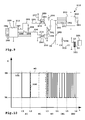
- the communication devices 289, 290, 304 communicate with different priorities on the data bus 36. Exemplary communication is in FIG. 10 shown.
- the second communication device 290 sends a bus message 305 on the data bus 36.
- the bus message 305 starts with a start pulse SI.
- the communication device 290 lowers a potential U on the data bus 36 from a high rest potential UH to a lower transmission potential UL.
- the data bus 36 is designed as an open-collector bus.
- the communication device 290 signals at the time t1 the desire to send a bus message.
- the start pulse ends and begins a waiting phase W1, within which the communication device 290 waits for transmission requests from other bus users of the data bus 36.
- the shorter waiting phase W2 compared to the waiting phase W1 signals that the bus message 306 has a higher priority than the bus message 305.
- the communication device 290 would omit further sending of the bus message 305 and give priority to the bus message 306.
- bus message 305 is described further below:
- an address information AD begins, which relates, for example, to the type of message and / or the sender of the message and / or the content of the message.
- This is followed at times t4 and t5 information pieces IN1, IN2, for example, contain four or eight bits of data.
- Bus messages on the data bus 36 may have variable lengths, that is, for example, that only the information part IN1 is transmitted or connect to the information part IN2 more, not shown information parts.
Landscapes
- Engineering & Computer Science (AREA)
- Mechanical Engineering (AREA)
- Microelectronics & Electronic Packaging (AREA)
- Details Of Connecting Devices For Male And Female Coupling (AREA)
- Portable Power Tools In General (AREA)
- Coupling Device And Connection With Printed Circuit (AREA)
Abstract
Description
- Die Erfindung betrifft eine portable elektrische Maschine, insbesondere eine Hand-Werkzeugmaschine oder ein Sauggerät, mit einem Leiterplattenmodul, das eine Leiterplatte aufweist, an der Leiterbahnen und über die Leiterbahnen elektrisch miteinander verbundene elektrische Komponenten an zumindest einer Flachseite angeordnet sind.
- Leiterplatten mit elektrischen Komponenten, beispielsweise Mikroprozessoren, Widerständen und dergleichen, sind bei elektrischen Vorrichtungen, beispielsweise elektrischen Hand-Werkzeugmaschinen, Sauggeräten und dergleichen, üblich. Ferner ist es notwendig, diese Maschinen mit elektrischen Versorgungsspannungen, beispielsweise zum Betrieb eines Elektromotors, insbesondere eines Saugmotors oder eines Motors zum Antrieb einer Werkzeugspindel, zu versorgen, wofür höhere Spannungspegel erforderlich sind. Auch das zugeordnete Massepotential und insbesondere Schutzleiterpotential sind notwendig. Für Versorgungsspannungen und zugeordnete Masse- und Schutzleiterpotentiale sind jedoch große Leiterquerschnitte erforderlich, wofür die Leiterbahnen der Leiterplatte ungeeignet sind. Dementsprechend verwendet man zur Verdrahtung höherer Potentiale beispielsweise Litzen oder Drähte zusätzlich zu den Leiterbahnen der Leiterplatte. Auch wenn entsprechende Potentiale auf der Leiterbahn an mehreren Stellen erforderlich sind, werden hierzu von den Leiterbahnen separate Leitungen benötigt, die im erforderlichen Umfang mit der Leiterplatte elektrisch verbunden sind, beispielsweise an diese angesteckt sind.
- Es ist daher die Aufgabe der vorliegenden Erfindung, ein verbessertes Leitungskonzept für ein Leiterplattenmodul mit einer Leiterplatte der eingangs genannten Art bereitzustellen.
- Zur Lösung der Aufgabe ist bei einer portablen elektrischen Maschine mit einem Leiterplattenmodul der eingangs genannten Art vorgesehen, dass an der die elektrischen Komponenten aufweisenden Flachseite oder einer dieser entgegengesetzten Flachseite der Leiterplatte eine Leitkörperanordnung mit mindestens einem von der Leiterplatte separaten Leitkörper angeordnet ist, und dass mindestens ein vor einen entlang der Flachseite verlaufenden Leitkörper-Verbindungsabschnitt vorstehender Leiterplatten-Kontaktvorsprung die Leiterplatte an einer Kontaktöffnung durchdringt oder in die Leiterplatte eindringt.
- Unterhalb der Leiterplatte verläuft mindestens ein Leitkörper-Verbindungsabschnitt, vor den der Leiterplatten-Kontaktvorsprung zur Durchdringung oder Eindringung in die Leiterplatte vorsteht. Der Leitkörper ist zumindest im Bereich des Leiterplatten-Kontaktvorsprungs und/oder des Leitkörper-Verbindungsabschnittes bezüglich einer Richtung biegesteif. Diese Richtung ist beispielsweise eine Einsteckrichtung zum Einstecken des Leiterplatten-Kontaktvorsprungs in die Kontaktöffnung der Leiterplatte. Dadurch wird die Montage vereinfacht.
- Die Kontaktöffnung verläuft zweckmäßigerweise von einer zur anderen Flachseite.
- Der Leitkörper ermöglicht einen größeren Leiterquerschnitt als die Leiterbahnen, so dass beispielsweise die Übertragung von Versorgungspotentialen, Massepotentialen und Schutzleiterpotentialen entlang der Leiterplatte vereinfacht ist. Vorzugsweise weist der Leitkörper einen größeren Leiterquerschnitt auf als jede der Leiterbahnen der Leiterplatte.
- Selbstverständlich können mehrere Kontaktvorsprünge und/oder mehrere Kontaktöffnungen an der Leiterplatte vorgesehen sein.
- Der Leitkörper dient vorzugsweise zum Anschluss einer elektrischen Versorgungsspannung und/oder eines Massepotentials und/oder eines Schutzleiterpotentials oder Erdungspotentials.
- Der Leiterplatten-Kontaktvorsprung kann an einer isolierten Stelle die Leiterplatte durchdringen oder in diese eindringen. Es ist aber auch möglich, dass der Leiterplatten-Kontaktvorsprung mit der Leiterplatte elektrisch verbunden ist. In diesem Zusammenhang sei betont, dass insbesondere zur Herstellung eines elektrischen Kontaktes zwischen einerseits dem Leitkörper und andererseits der Leiterplatte beziehungsweise einer Leiterbahn derselben ein Eindringen des Kontaktvorsprunges ausreicht.
- Bei einer bevorzugten Ausgestaltung der Erfindung durchdringt der Leiterplatten-Kontaktvorsprung die Kontaktöffnung und ist als Steckvorsprung zum Anstecken eines elektrischen Steckverbinders ausgestaltet. Der Steckvorsprung kann beispielsweise ein Einsteck-Steckvorsprung sein, der in einer entsprechenden Aufnahme des anzusteckenden Steckverbinders vorgesehen ist. Dieser ist zum Beispiel als eine Buchse ausgestaltet. Aber auch die umgekehrte Konfiguration kann getroffen sein, dass nämlich der Leiterplatten-Kontaktvorsprung als Steckaufnahme zur Aufnahme eines einen Steckvorsprung aufweisenden, an das Leiterplattenmodul anzuschließenden Steckverbinders aufweist.
- Der mindestens eine Leitkörper weist zweckmäßigerweise einen Anschlussabschnitt auf, der zum elektrischen Anschluss einer weiteren Komponente, beispielsweise eines Steckverbinders, eines Kabels oder dergleichen, an mindestens einer Seite vor die Leiterplatte vorsteht. Zweckmäßigerweise sind zwei solche Anschlussabschnitte vorgesehen, die an verschiedenen Seiten, vorzugsweise an einander entgegengesetzten Seiten, jeweils vor die Leiterplatte vorstehen.
- Der Leitkörper hat vorzugsweise eine Längsgestalt. Der oder die Anschlussabschnitte bilden dann entsprechend Längsenden des Leitkörpers. Es versteht sich, dass auch ein winkeliger oder gekrümmter Leitkörper im Sinne der Erfindung ist.
- An dem Anschlussabschnitt ist zweckmäßigerweise mindestens ein Leitkörper-Steckanschluss, beispielsweise eine Steckaufnahme oder ein Steckvorsprung, für einen elektrischen Steckverbinder angeordnet. Der Steckvorsprung ist zweckmäßigerweise gleich ausgestaltet wie der Leiterplatten-Kontaktvorsprung. Mithin haben also zweckmäßigerweise sämtliche Steckvorsprünge oder Steckanschlüsse, die an dem mindestens einen Leitkörper angeordnet sind, die gleiche mechanische Ausgestaltung, insbesondere die gleiche geometrische Gestalt.
- Die obige Maßnahme ist zwar zweckmäßig, jedoch nicht unbedingt notwendig für die nachfolgend beschriebene bevorzugte Ausgestaltung der Erfindung: Der mindestens eine Leitkörper-Steckanschluss und/oder der Leiterplatten-Kontaktvorsprung bilden zweckmäßigerweise Bestandteile einer mehrpoligen Steckanschlussanordnung zum Anschluss eines mehrpoligen elektrischen Steckverbinders. Die Mehrpoligkeit kann beispielsweise dadurch realisiert werden, dass neben dem mindestens einen Leitkörper mindestens ein zweiter, vorzugsweise jedoch weitere, beispielsweise drei oder vier erfindungsgemäße Leitkörper angeordnet sind, die entsprechende Leiterplatten-Kontaktvorsprünge beziehungsweise Leitkörper-Steckanschlüsse aufweisen, die zum Anschluss eines mehrpoligen elektrischen Steckverbinders geeignet sind.
- Die Steckanschlussanordnung kann jedoch neben den Kontakten, die von einem oder mehreren erfindungsgemäßen Leitkörpern bereitgestellt werden, auch einen weiteren Kontakt aufweisen, der als ein Leiterplatten-Steckanschluss ausgestaltet ist. Dieser ist elektrisch ausschließlich mit der Leiterplatte verbunden und von dem Leitkörper elektrisch isoliert. Beispielsweise kann der weitere Leiterplatten-Steckanschluss - es können auch mehrere vorgesehen sein - als eine Lötfahne oder Steckfahne ausgestaltet sein. Die geometrische Ausgestaltung des separaten Leiterplatten-Steckanschlusses entspricht vorzugsweise dem Leiterplatten-Kontaktvorsprung und/oder dem Leitkörper-Steckanschluss.
- Zwischen dem mindestens einen Leitkörper und der Leiterplatte ist zweckmäßigerweise ein Zwischenkörper angeordnet. Zwar kann dieser prinzipiell eine beliebige geometrische Gestalt aufweisen. Bevorzugt ist jedoch eine plattenartige Gestalt, zumindest im Bereich unterhalb der Leiterplatte. Weiterhin ist es vorteilhaft, wenn an einer von der Leiterplatte abgewandten Seite des mindestens einen Leitkörpers ein weiterer Bodenkörper vorgesehen ist. Der Bodenkörper ist zweckmäßigerweise plattenförmig und/oder wannenartig. Es versteht sich, dass nur der Zwischenkörper oder nur der Bodenkörper vorgesehen sein können. Bevorzugt ist jedoch die Ausgestaltung des Leiterplattenmoduls derart, dass sowohl der Zwischenkörper als auch der Bodenkörper vorhanden sind. Mindestens ein Leitkörper, zweckmäßigerweise alle Leitkörper der Leitkörperanordnung, verlaufen zweckmäßigerweise in einem Zwischenraum zwischen dem Zwischenkörper und dem Bodenkörper.
- Der Bodenkörper und/oder der Zwischenkörper weisen zweckmäßigerweise eine Leitkörper-Aufnahme zur Aufnahme des mindestens einen Leitkörpers auf. Zweckmäßigerweise ist die Ausgestaltung so getroffen, dass sowohl der Bodenkörper als auch der Zwischenkörper Aufnahmen für den Leitkörper oder die Leitkörper aufweisen. Zweckmäßigerweise ist die Anordnung so getroffen, dass sich die Leitkörper-Aufnahmen des Bodenkörpers und des Zwischenkörpers in Längserstreckungsrichtung des mindestens einen Leitkörpers, den sie aufnehmen, hintereinander erstrecken. Aber auch ineinandergreifende Leitkörper-Aufnahmen am Bodenkörper und Zwischenkörper sind möglich, so dass diese insgesamt den Leitkörper halten und fixieren oder vorfixieren. Die vorgenannte Maßnahme sorgt dafür, dass der Leitkörper durch den Bodenkörper und/oder den Zwischenkörper gehalten wird, gegebenenfalls auch unabhängig von der Leiterplatte.
- Zweckmäßigerweise stellen der Bodenkörper und/oder der Zwischenkörper auch eine Seitenbegrenzung für die Leiterplatte bereit. Beispielsweise kann an einem oder beiden der Körper an zumindest einer Seite eine Seitenwand oder Umfangswand vorgesehen sein, die die Leiterplatte seitlich begrenzt.
- Eine bevorzugte Ausgestaltung der Erfindung sieht vor, dass der Zwischenkörper und/oder der Bodenkörper elektrisch isolierend sind. Beispielsweise besteht der jeweilige Körper zumindest teilweise aus Kunststoff und/oder hat eine elektrisch isolierende Beschichtung. Dadurch ist es beispielsweise möglich, dass der vorzugsweise elektrisch nicht isolierte Leitkörper elektrisch von der Umgebung, insbesondere der Leiterplatte, isoliert ist. Es versteht sich, dass auch der Leitkörper insbesondere abschnittsweise, beispielsweise an dem Leitkörper-Verbindungsabschnitt, elektrisch isoliert sein kann. Eine elektrische Isolierung des Zwischenkörpers und/oder des Bodenkörpers ist dann zwar vorteilhaft, jedoch nicht unbedingt notwendig.
- An dem Zwischenkörper oder dem Bodenkörper oder der Leiterplatte ist vorteilhaft ein Isolationskörper, beispielsweiseals Bestandteil eines Steckverbindergehäuses, als eine Isolationswand, ein Isolationsvorsprung oder dergleichen, angeordnet, der zur elektrischen Isolation eines Steckanschlusses dient. Dieser Steckanschluss wird beispielsweise durch den Leitkörper bereitgestellt, zum Beispiel den Leiterplatten-Kontaktvorsprung oder den Steckanschluss am Anschlussabschnitt des Leitkörpers. Dadurch ist es beispielsweise möglich, elektrisch nicht isolierte Steckverbinder, beispielsweise an elektrische Kabel angecrimpte Steckbuchsen oder dergleichen, elektrisch isoliert und geschützt an das Leiterplattenmodul anzuschließen. Ein separates, in der Fertigung aufwendiges Steckergehäuse oder Isolationsmedium ist dann nicht erforderlich.
- Es versteht sich, dass an dem Leiterplattenmodul, beispielsweise der Leiterplatte oder dergleichen, auch eine Steckerkodierung vorgesehen sein kann, die ein verpolungssicheres Einstecken des externen Steckverbinders gewährleistet. Beispielsweise kann das vorher erläuterte, bevorzugte Steckverbindergehäuse als eine Kodierung ausgestaltet sein. Aber auch ein sonstiger Isolationskörper, beispielsweise eine Isolationswand oder dergleichen, kann in Gestalt einer Kodierung ausgestaltet sein. Ferner ist es möglich, durch eine Beabstandung oder eine Anordnung der Steckanschlüsse, die durch beispielsweise den Leiterplatten-Kontaktvorsprung und/oder den Leitkörper-Steckanschluss am Anschlussabschnitt gebildet werden, eine Kodierung zu realisieren.
- Zweckmäßigerweise ist ein zumindest teilweises Vergießen des Leiterplattenmoduls vorgesehen. Dieses weist zweckmäßigerweise eine Vergussschicht auf. Diese dient beispielsweise dazu, den Leitkörper an dem Leiterplattenmodul zu fixieren. Beispielsweise ist die Vergussschicht zwischen der Leiterplatte und dem Zwischenkörper und/oder zwischen dem Zwischenkörper und dem Bodenkörper angeordnet.
- Zumindest ein Abschnitt des mindestens einen Leitkörpers, vorzugsweise aller Leitkörper der Leitkörperanordnung, sind zweckmäßigerweise in einem Wannenbereich des Bodenkörpers und/oder des Zwischenkörpers aufgenommen. Dieser Wannenbereich ist zweckmäßigerweise mit der oben erläuterten Vergussmasse zumindest teilweise verfüllt, was einen sicheren Halt der jeweiligen Komponenten aneinander realisiert. Auch der Zwischenkörper und die Leiterplatte sind zweckmäßigerweise in einem dann am Bodenkörper vorgesehenen Wannenbereich angeordnet. Es versteht sich, dass die Leiterplatte auch an einem Wannenbereich des Zwischenkörpers anordenbar ist.
- Der Leitkörper hat zweckmäßigerweise eine Plattengestalt oder eine Flachgestalt. Eine Leitkörper-Flachseite des Leitkörpers verläuft zweckmäßigerweise quer, beispielsweise senkrecht, zur benachbarten Flachseite der Leiterplatte. Dadurch ist eine Biegesteifheit quer zur Flachseite der Leiterplatte realisiert.
- Der Leiterplatten-Kontaktvorsprung und/oder der Leitkörper-Steckanschluss stehen zweckmäßigerweise vor eine Schmalseite des mindestens einen Leitkörpers vor.
- Ein spielarmes, jedoch einfaches Einstecken wird durch die nachfolgende Maßnahme realisiert: Die mindestens eine Kontaktöffnung verläuft bezüglich des Leiterplatten-Kontaktvorsprungs zumindest abschnittsweise schräg oder gebogen, insbesondere im Querschnitt, so dass der Leiterplatten-Kontaktvorsprung punktförmig, beispielsweise in einer Dreipunktlage oder Zweipunktlage, an einer Innenkontur der mindestens einen Kontaktöffnung anliegt. Die Kontaktöffnung hat beispielsweise eine sichelförmige, bananenförmige, im Wesentlichen dreikantartige oder dergleichen Innenkontur. Die Innenkontur ermöglicht zweckmäßigerweise eine Mehrpunktanlage, jedoch keine flächige Anlage, was das Einstecken des Kontaktvorsprungs in die Kontaktöffnung erleichtert.
- Weiterhin ist es vorteilhaft, dass der mindestens eine Leitkörper eine oder mehrere mechanische Kodierungen aufweist. Beispielsweise hat der Leitkörper einen Kodiervorsprung, der in eine an der Leiterplatte, dem Zwischenkörper, dem Bodenkörper oder dergleichen vorgesehene Kodieraufnahme eingreift. Der Kodiervorsprung kann beispielsweise ein Kontaktvorsprung sein, der am geeigneten Montageplatz des Leitkörpers in eine korrespondierende Kodieraufnahme an der jeweils anderen Komponente des Leiterplattenmoduls eingreift. Es versteht sich, dass auch die umgekehrte Anordnung getroffen sein kann, dass nämlich der Leitkörper eine Kodieraufnahme aufweist, die zum Eingriff eines beispielsweise an der Leiterplatte, dem Zwischenkörper oder dem Bodenkörper vorgesehenen Kodiervorsprungs ausgestaltet ist. Weiterhin ist es vorteilhaft, wenn der Leitkörper eine Steckerkodierung zur polrichtigen Verbindung mit einem Steckverbinder aufweist, so dass eine Fehlkontaktierung oder ein Fehlanschluss des an das Leiterplattenmodul anzuschließenden Steckverbinders vermieden wird.
- Vorzugsweise hat die Leitkörperanordnung mehrere, beispielsweise zwei oder mehr Leitkörper. Diese Leitkörper vorlaufen vorzugsweise parallel nebeneinander, wobei auch ein Querverlauf oder Schrägverlauf prinzipiell möglich ist.
- Besonders bevorzugt ist die Erfindung in Zusammenhang mit portablen elektrischen Maschinen, beispielsweise Hand-Werkzeugmaschinen, Sauggeräten oder dergleichen.
- Nachfolgend wird ein Ausführungsbeispiel der Erfindung anhand der Zeichnung erläutert. Es zeigen:
- Figur 1
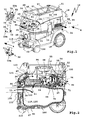
- eine perspektivische Frontal-Schrägansicht eines Sauggerätes,
- Figur 2
- eine Querschnittsansicht des Sauggeräts gemäß
Figur 1 etwa entlang einer Schnittlinie A-A inFigur 1 , - Figur 3
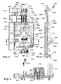
- eine Draufsicht auf ein erfindungsgemäßes Leiter- plattenmodul,
- Figur 4
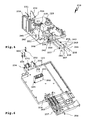
- eine perspektivische Schrägansicht des Leiter- plattenmoduls gemäß
Figur 3 , jedoch ohne einen Bo- denkörper, - Figur 5
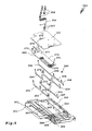
- eine Explosionsdarstellung des Leiterplattenmoduls gemäß
Figur 3 , - Figur 6
- das Leiterplattenmodul gemäß
Figur 3 schräg von oben, allerdings ohne auf der Leiterplatte angeord- nete elektrische Komponenten, - Figur 7
- eine Querschnittsansicht des Leiterplattenmoduls gemäß
Figur 3 entlang einer Schnittlinie B-B, - Figur 8
- eine Querschnittsansicht des Leiterplattenmoduls gemäß
Figur 3 entlang einer Schnittlinie C-C, - Figur 9
- ein Teilschaltbild einer Steuerungseinrichtung des Sauggeräts gemäß
Figur 1 und - Figur 10
- eine Busnachricht, die auf einem Bus der Steue- rungseinrichtung gemäß
Figur 9 übertragen wird. - Im Inneren eines Saugergehäuses 11 eines Sauggeräts 10 ist ein Saugmotor 12 zum Erzeugen eines Saugstroms 13 angeordnet, der über einen Saugeinlass 14 in das Saugergehäuse 11 einsaugbar ist. An den Saugeinlass 14 ist ein nicht dargestellter Schlauch anschließbar. Im Inneren des Saugergehäuses 11 befindet sich ferner eine Filteranordnung 15 zum Absondern von Partikeln aus dem Saugstrom 13.
- An einer Oberseite 16 des Saugergehäuses 11 befindet sich eine Aufnahme 17 zur Aufnahme des Saugschlauches und/oder eines Anschlusskabels 18, mit dem das Sauggerät 10 an ein elektrisches Versorgungsnetz mit z.B. 110 Volt oder 230 Volt Wechselstrom anschließbar ist. Alternativ wäre ein Sauggerät mit einem Akkumulator möglich. Das Sauggerät 10 ist ein transportables Sauggerät, an dessen Unterseite Fahrrollen 19, 20 angeordnet sind. Die vorderen Fahrrollen 20 sind Lenkrollen. Weiterhin kann das Sauggerät 10 an einem Tragegriff 21 an der Oberseite 16 ergriffen werden.
- Zwischen einer den Saugeinlass 14 aufweisenden Frontwand 22 und der Oberseite 16 des Saugergehäuses 11 erstreckt sich eine Bedienwand 23 mit Bedienelementen 24 zur Bedienung des Sauggeräts 10. Die Bedienwand 23 ist zweckmäßigerweise schräg geneigt, so dass die Bedienelemente 24 von schräg oben vorn leicht bedienbar sind.
- Die Bedienelemente 24 umfassen einen Schalter 25, der sozusagen einen Hauptschalter bildet. Mit dem Schalter 25 kann der Saugmotor 12 ein- und ausgeschaltet werden. Ferner ist ein Automatikmodus einstellbar, bei dem der Saugmotor 12 immer dann läuft, wenn ein angeschlossener Verbraucher elektrischen Strom über das Sauggerät 10 erhält, was später noch erläutert wird. Mit Hilfe eines Saugleistungs- oder Drehzahlschalters 26 kann eine Leistung des Saugmotors 12 eingestellt werden. Ein Anpassungsschalter 27 ermöglicht eine elektrische Anpassung des Sauggeräts 10 an einem jeweiligen Saugeinlass 14 angeschlossenen Saugschlauch. Mit einem Reinigungsschalter 28 ist eine Reinigungsfunktion des Sauggeräts 10 einschaltbar und/oder parametrierbar. Eine fest am Sauggerät 10 installierte Steckdose 29 ermöglicht das Einstecken eines elektrischen Energieverbrauchers. Die Steckdose 29 ist mit dem Anschlusskabel 18 elektrisch verbunden.
- In einem unteren Teil, einem Sammelgehäuseteil 31, des Saugergehäuses 11 ist ein dem Innenraum 47 oder Sammelraum 110 zum Sammeln von aus dem Saugstrom 13 abgesonderten Partikeln und/oder abgesonderter Feuchtigkeit vorgesehen, in dem optional ein großformatiger Filtersack 48 der Filteranordnung 15 anordenbar ist. Einem zum Saugmotor 12 führenden Saugeinlass 56 ist ein Hauptfilter 61 vorgelagert.
- Der Saugstrom 13 wird durch den Saugeinlass 14, an dem ein Saugschlauch 190 anordenbar ist, in den Filtersack 48 eingesaugt. Der Filtersack 48 nimmt im Saugstrom 13 enthaltene Partikel 180 auf. Der Saugstrom 13 wird vom Saugmotor 12 erzeugt, der den Saugstrom 13 über den Hauptfilter 61 durch den Saugeinlass 56 hindurch ansaugt. Der Saugeinlass 56 ist strömungsabseitig, beim Sauggerät 10 oberseitig, des Hauptfilters 61 angeordnet. Der Saugeinlass 56 ist mit einem Turbineneinlass 70 einer Saugturbine 71 eines den Saugmotor 12 enthaltenden Motormoduls 58 über eine Luftführungsanordnung 55 verbunden. Die Saugturbine 71 saugt den Saugstrom 13 durch den Turbineneinlass 70 an und bläst ihn nach radial außen über Schalldämpfer 84, die zugleich optional eine Filterfunktion haben können, hindurch und sodann durch Saugstromauslässe 85 an den Seitenwänden des Saugergehäuses 11 nach außen aus dem Saugergehäuse 11 hinaus.
- Ein Kühlluftstrom 94 strömt durch einen Kühllufteinlass 96 an der Frontwand 22 des Saugergehäuses 11 ein. Der Kühlluftstrom 94 strömt zunächst an einer Steuerungseinrichtung 97 des Sauggeräts 10 vorbei und kühlt diese. Über einen zwischen dem Hauptfilter 61 und einer Deckwand 52 des Saugergehäuses 11 verlaufenden Kühlluftkanal 98 strömt der Kühlluftstrom 94 weiter zu einem Motoraufnahmeraum 54 für den Saugmotor 12, in dem der Kühlluftstrom 94 von oben her in einen Kühllufteinlass des Saugmotors 12 einströmt. Der Kühlluftstrom 94 durchströmt den Saugmotor 12 und strömt sodann nach hinten durch einen Kühlluftauslass 99 aus dem Saugergehäuse 11 aus, an dem zweckmäßigerweise ein Schalldämpfer 100 vorgesehen ist.
- An einem Saugrohranschluss 133, an den der Saugschlauch 190 anschließbar ist, ist ein Erdungskontakt 137 vorgesehen. Der Erdungskontakt 137 ist als ein Federkontakt, beispielsweise eine Federzunge, ausgestaltet. Der Saugrohranschluss 133, z.B. eine Rohrmuffe, und/oder der Saugschlauch 190 bestehen zweckmäßigerweise aus einem elektrisch leitfähigen Material, insbesondere Kunststoff, insbesondere in einem für den Erdungskontakt 137 vorgesehenen Berührbereich.
- Ein Sensor 121 detektiert einen Füllstand einer Flüssigkeit oder einer sonstigen elektrisch leitfähigen Substanz in dem Sammelraum 110 und generiert in Abhängigkeit davon ein Sensorsignal. Der Sensor 121 ist vorzugsweise auf einer Leiterplatte 123 der Steuerungseinrichtung 97 angeordnet. Von einer Außenseite des Saugergehäuses 11 elektrisch abtastbare (siehe
Figur 1 ) Erfassungsteile 119, 120 des Sensors 121 stehen in den Sammelraum 110, mithin also in Innenraum 47 des Sammelgehäuseteils 31, vor. Signalverbindungen zwischen den Erfassungsteilen 119, 120 außerhalb des Sammelraums 110, jedoch elektrisch geschützt und verdeckt am Saugergehäuse 11. - Die Steuerungseinrichtung 97 ist mit den Bedienelementen 24 beeinflussbar. Zweckmäßigerweise ist die Leiterplatte 123 unterhalb der Bedienelemente 24 angeordnet, d.h. unterhalb der Bedienwand 23. Die Steuerungseinrichtung 97 ist mit dem Saugmotor 12, insbesondere dem Motormodul 58 über nicht dargestellte elektrische Leitungen verbunden und steuert diesen.
- An der Bedienwand 23 ist eine zweckmäßigerweise in der Art eines Aufnahmeschachtes ausgestaltete, in
Figur 1 mit einer Abdeckplatte 38 abgedeckte Modulaufnahme 30 zur wahlweisen Aufnahme von Funktionsmodulen 50a-50c vorgesehen, die elektrische, optische und akustische Funktionen bereitstellen. - Das Funktionsmodul 50a ist z.B. ein Druckluft-Modul zum Anschließen eines Druckluft-Werkzeuges. Das Funktionsmodul 50a hat eine Druckluft-Anschlussanordnung 51 mit Druckluft-Anschlüssen, an die jeweils ein Druckluftschlauch anschließbar ist. Somit kann also eine Druckluftverbindung über die Anschlussanordnung 51 durch das Funktionsmodul 50a durchgeschleift werden, wobei ein Druckluftpfad im Funktionsmodul 50a über einen Druckluftsensor zum Erfassen eines Druckluftstromes führt. Der Druckluftsensor ist über Modulsignalkontakte 32 mit Sauggerät-Signalkontakten 33 elektrisch verbunden, wenn das Funktionsmodul 50a in die Modulaufnahme 30 eingesteckt ist.
- Das Funktionsmodul 50b weist einen Bus-Anschluss 34 mit einem Buskontakt 35 zum Anschluss an einen Datenbus 36 des Sauggeräts 10 auf. Ein Buskontakt 35 der Sauggerät-Signalkontakte 33 ist mit dem Funktionsmodul 50b verbindbar.
- Das Funktionsmodul 50c weist z.B. einen elektrischen Stromversorgungsanschluss 73 zum Anschluss eines elektrischen Verbrauchers, beispielsweise eines Elektro-Werkzeugs, auf. Der Stromversorgungsanschluss 73 umfasst eine Steckdose 74, vorzugsweise eine Schutzkontaktsteckdose, die mittels eines Deckels 75 verschließbar ist. Kontakte 76, 77 und 78 der Steckdose 74 sind über Leitungen mit Kontakten eines Steckverbinders 82 verbunden. Der Steckverbinder 82 dient zur Herstellung elektrischer Verbindungen zu Versorgungskontakten 83 im Innern der Modulaufnahme 30 des Sauggeräts 10, die z.B. für eine Schutzleiterverbindung, eine Masseverbindung und eine Dauerstrom-Verbindung vorgesehen sind.
- Die Steuerungseinrichtung 97, insbesondere die Anordnung der Leiterplatte 123, sowie das damit in Beziehung stehende elektrische Anschlusskonzept, unter anderem zum Anschluss der Funktionsmodule 50a, 50b oder 50c, sind bei dem Sauggerät 10 innovativ und auf erfindungsgemäße Weise gelöst:
- Die Leiterplatte 123 bildet einen Bestandteil eines Leiterplattenmoduls 210, auf der elektrische Komponenten 211, beispielsweise ein erster und ein zweiter Mikroprozessor 212, 213, die zweckmäßigerweise über Optokoppler 214, 215 oder sonstige galvanisch trennende Komponenten miteinander kommunizieren, Leistungshalbleiter zur Ansteuerung beispielsweise des Saugmotors 12, zum Beispiel ein Triac 216, an einem Kühlkörper 217 sowie weitere, hier nicht im Detail beschriebene Komponenten, beispielsweise Widerstände, Kondensatoren und dergleichen, angeordnet sind. Die elektrischen Komponenten 211 sind auf einer oberen Flachseite 218 angeordnet. An der Flachseite 218 sowie einer dieser gegenüberliegenden unteren Flachseite 219 der Leiterplatte 123 verlaufen schematisch angedeutete Leiterbahnen 220 zur Verbindung der elektrischen Komponenten 211. Weiterhin sind die Bedienelemente 24 elektrisch und/oder mechanisch mit der Steuerungseinrichtung 97 verbunden. Beispielsweise sind Steuerglieder 221, 222 vorgesehen, zum Beispiel Potentiometer, die beispielsweise mit dem Saugleistungsschalter 26, dem Anpassungsschalter 27 sowie dem Reinigungsschalter 28 mechanisch verbunden sind. Somit kann beispielsweise eine Saugleistung des Saugmotors 12, eine Betriebsart oder dergleichen an der Steuerungseinrichtung 97 vorgewählt werden.
- Zur elektrischen Verbindung von Sensoren oder Sensorflächen, zum Beispiel der Erfassungsteile 119, 120, sind an der Leiterplatte 123 Sensoranschlüsse 223 vorgesehen, beispielsweise Pfostenstecker.
- Die Sauggerät-Signalkontakte 33 sind mit Leiterplatten-Signalkontakten 224 elektrisch verbunden. Signalanschlüsse 225 dienen zum Anschluss weiterer Sensoren, beispielsweise eines Temperatursensors für den Saugmotor 12, eines Strömungs- oder Drucksensors für den Saugstrom 13 oder dergleichen.
- Der erste Mikroprozessor 212 befindet sich auf einem ersten Potentialbereich 226 der Leiterplatte 123 und ist mit den dort befindlichen Komponenten 211 vernetzt, während der zweite Mikroprozessor 213 in einem zweiten Potentialbereich 227 angeordnet ist und mit den dortigen Komponenten 211 verbunden ist, beispielsweise mit den Sensoranschlüssen 223 oder den Signalkontakt-Anschlüssen 224, 225. Der erste Potentialbereich 226 ist mit einem Netzpotential, das über das Anschlusskabel 18 kommt, verbunden, während der zweite Potentialbereich 227 ein im Vergleich zum Potentialbereich 226 niedrigeres elektrisches Potential aufweist, beispielsweise in Höhe von Signalspannungen von 5 bis 12 Volt oder dergleichen. Somit ist ein Berührkontakt seitens eines Bedieners bezüglich des zweiten Potentialbereichs 227 möglich, was zum Beispiel im Bereich der Erfassungsteile 119 oder 120 nicht auszuschließen ist. Durch die Optokoppler 214, 215 ist eine Potentialtrennung zwischen den beiden Potentialbereichen 226, 227 realisiert, so dass der Bediener mit dem im Potentialbereich 226 vorhandenen höheren elektrischen Potential nicht in Berührung kommt.
- In
Figur 3 ist der zweite Potentialbereich 227 in gestrichelten Linien angedeutet. Der übrige Bereich der Leiterplatte 123 ist dem ersten Potentialbereich 226 zugeordnet. - Nicht nur im Hinblick auf eine optimierte Potentialtrennung auf der Leiterplatte 123 ist die elektrische Beschaltung und Verdrahtung bei dem Sauggerät 10, insbesondere dessen Steuerungseinrichtung 97, optimal, sondern auch im Hinblick auf das übrige Verdrahtungs- und Anschlusskonzept.
- Über das Anschlusskabel 18 kommen beispielsweise ein Netzpotential 230, ein Massepotential 231 sowie ein Schutzleiterpotential 232, die über eine nicht dargestellte Verbindungsleitung sowie über Steckverbinder 233 an eine Steckanschlussanordnung 234 des Leiterplattenmoduls 210 angeschlossen sind. Die Steckanschlussanordnung 234 ist elektrisch mit weiteren mehrpoligen Steckanschlussanordnungen 235 zum elektrischen Anschluss des Schalters 25 des Hauptschalters, zum elektrischen Anschluss des Funktionsmoduls 50c sowie einer Steckanschlussanordnung 237 zur Verbindung mit der Steckdose 29 verbunden. Dazu sind Leitkörper 238-242 einer Leitkörperanordnung 243 vorgesehen, die an der unteren Flachseite 219 der Leiterplatte 123 entlang verlaufen. Die Leitkörper 238-242 haben eine Flachgestalt. Ihre Schmalseiten 244 sind der unteren Flachseite 219 zugewandt.
- An den Schmalseiten 244 stehen bei den Leitkörpern 238-242 Kontaktvorsprünge vor, nämlich die Leiterplatte 123 an Kontaktöffnungen 245, 246 durchdringende Leiterplatten-Kontaktvorsprünge 247, 248, die Bestandteile der Steckanschlussanordnungen 235, 236 bilden, sowie Leitkörper-Steckanschlüsse 249, 250, die Bestandteile der Steckanschlussanordnungen 234, 237 bilden.
- Die die Leiterplatte 123 durchdringenden Leiterplatten-Kontaktvorsprünge 247, 248 sowie die Leitkörper-Steckanschlüsse 249, 250 sind als Steckvorsprünge ausgestaltet, die jeweils vor die obere Flachseite 218 der Leiterplatte 123 vorstehen. Dort stehen sie zur Kontaktierung durch einen jeweiligen, insbesondere mehrpoligen Steckverbinder bereit, beispielsweise einen mehrpoligen Steckverbinder 251, der auf die Steckanschlussanordnung 235 aufgesteckt ist. Der Steckverbinder 251 weist in seinem Inneren mehrere den Steckverbindern 233 entsprechende Anschlussbuchsen oder Steckanschlüsse 257 auf, die vorzugsweise in einem Steckergehäuse 252 angeordnet sind. Die Leiterplatten-Kontaktvorsprünge 247, 248 stehen nach oben vor Leitkörper-Verbindungsabschnitte 253 der Leitkörper 238-242 vor, die entlang der unteren Flachseite 219 der Leiterplatte 123 verlaufen. Vor die Leiterplatte 123 stehen Anschlussabschnitte 254, 255 der Leitkörper 238-242 vor, an denen die Steckanschlüsse 249, 250 vorgesehen sind. Die Steckanschlüsse 249, 250 stehen zur selben Seite wie die Kontaktvorsprünge 247, 248 vor, wobei es durchaus möglich ist, dass Kontaktvorsprünge und/oder Steckanschlüsse bei erfindungsgemäß verwendeten Leitkörpern an unterschiedlichen Seiten, insbesondere entgegengesetzte Seiten, vorstehen. So steht beispielsweise beim Leitkörper 238 ein Steckanschluss 256 in dessen Längserstreckungsrichtung nach vorn vor, das heißt quer zu den Leitkörper-Steckanschlüssen 250. Der Steckanschluss 256 dient zum Anschluss einer Steckverbinderbuchse in der Art der Steckverbinder 233, um eine elektrische Verbindung zu dem Erdungskontakt 137 am Saugrohranschluss 133 herzustellen.
- Sämtliche elektrischen Kontakte der Steckanschlussanordnungen 234, 236, 237 sind durch Kontaktvorsprünge der Leitkörperanordnung 243 realisiert. Bei der Steckanschlussanordnung 235, die für das Funktionsmodul 50c vorgesehen ist, sind noch zwei weitere elektrische Steckverbinder beziehungsweise elektrische Steckanschlüsse 257 vorhanden, die ausschließlich in elektrischer Verbindung mit der Leiterplatte 123 stehen.
- Durch wahlweise Bestückung von Aufnahmekammern des Steckergehäuses 252 mit Steckbuchsen 258 und an diese jeweils angeschlossene elektrische Leitungen ist es beispielsweise möglich, unterschiedliche Verdrahtungsvarianten zu realisieren, ohne Modifikationen am Leiterplattenmodul 210 vorzunehmen. Eine solche Vorgehensweise ist selbstverständlich auch bezüglich der anderen Steckanschlussanordnungen 234, 236, 237 möglich, an die je nach Bedarf, beispielsweise für unterschiedliche Ländervarianten, unterschiedliche Anschlussleitungen beziehungsweise Steckverbinder angeschlossen werden können. Die beiden Steckanschlüsse 257, die ausschließlich mit der Leiterplatte 123 verbunden sind, ermöglichen beispielsweise eine Erfassung eines über die Steckdose 74 fließenden Stromes, so dass die Steuerungseinrichtung 97 den Saugmotor 12 bei fließendem Strom, das heißt bei einem an das Sauggerät 10 angeschlossenen, laufenden elektrischen Gerät, den Saugmotor 12 einschaltet. Ferner ist es möglich, dass die Steckdose 74 schaltbar ausgestaltet ist, so dass sie beispielsweise nur dann Strom liefert, wenn der Schalter 25 in Betriebsstellung geschaltet ist.
- Die Leitkörper 238-242 haben Leiterquerschnitte, die größer sind als die Leiterquerschnitte der Leiterbahnen 220, so dass sie größere Ströme leiten können. Dies ist insbesondere im Hinblick auf den Leitkörper 238, der das Schutzleiterpotential 232 leitet, wesentlich. Der Leitkörper 238 hat keinen elektrischen Kontakt zu der Leiterplatte 123 beziehungsweise den darauf angeordneten Leiterbahnen 220 oder elektrischen Komponenten 211. Der Leitkörper 238 durchdringt die Leiterplatte 123 lediglich im Bereich der Steckanschlussanordnung 236 mit einem Leitkörper-Kontaktvorsprung 248. Unterhalb der etwa im Bereich einer Längsmitte der Leiterplatte 123 angeordneten Steckanschlussanordnung 235 ist jedoch kein elektrischer Kontakt zur Leiterplatte 123 und insbesondere nicht zur Steckanschlussanordnung 235 vorhanden. Dies ist durch das erfindungsgemäße Konzept möglich.
- Allein schon durch einen Isolationsabstand zwischen der unteren Flachsseite 219 und dem Leitkörper 238 ist eine elektrische Isolation, insbesondere im Bereich der Steckanschlussanordnung 235, realisiert. Zudem ist noch zwischen der Leiterplatte 123 und der Leitkörperanordnung 243 ein im Wesentlichen plattenartiger Zwischenkörper 260 angeordnet, der zweckmäßigerweise elektrisch isolierend ist. Der Zwischenkörper 260 besteht beispielsweise aus Kunststoffmaterial und erstreckt sich zumindest im Bereich der Leitkörperanordnung 243 unterhalb der Leiterplatte 123. Unterhalb des Zwischenkörpers 260 ist sozusagen als Boden oder Basis ein Bodenkörper 261 angeordnet. Die Leiterplatte 123, der Zwischenkörper 260, die Leitkörperanordnung 243 sowie schließlich der Bodenkörper 261 bilden die wesentlichen Komponenten des Leiterplattenmoduls 210. Diese Komponenten sind zweckmäßigerweise insgesamt vergossen, was sowohl in mechanischer Hinsicht als auch in elektrisch isolierender Hinsicht vorteilhaft ist.
- Die Leiterplatte 123, der Zwischenkörper 260 sowie die darunter verlaufenden Leitkörper-Verbindungsabschnitte 253 der Leitkörper 238-242 sind in einer Wanne oder einem Wannenbereich 262 des Bodenkörpers 261 aufgenommen. Entlang der Schmalseiten der Leiterplatte 123 erstreckt sich eine Umfangswand 263 des Bodenkörpers 261. Insbesondere der Wannenbereich 262 eignet sich zu einer Verfüllung mit einer Vergussmasse, was das Leiterplattenmodul 210 mechanisch stabilisiert und elektrisch isoliert.
- Bezüglich der Längserstreckungsrichtung der Leitkörper 238-242 ist neben dem Wannenbereich 262 ein Anschlussbereich 264 des Basis- oder Bodenkörpers 261 angeordnet, der mit dem Wannenbereich 262 einstückig ist und die Anschlussabschnitte 255 der Leitkörper 238, 239 und 241 aufnimmt. Für diese sind Leitkörper-Aufnahmen 265 vorgesehen. Die Leitkörper 238, 239, 241 liegen mit ihren Flachseiten an Innenwänden der Leitkörper-Aufnahmen 265 im Wesentlichen flächig an, so dass sie einen festen Halt haben. Zudem haben die Leitkörper-Aufnahmen 265 Steckaufnahmen 266 an ihren vom Wannenbereich 262 abgewandten Endbereichen, in die Steckenden 267 der Leitkörper 239, 241 einsteckbar beziehungsweise der Steckanschluss 256 durchsteckbar ist. Der Steckanschluss 256 steht nach vorn vor eine Stirnwand des Leiterplattenmoduls 210 vor.
- Die Leitkörper-Aufnahmen 265 erstrecken sich auch in den Wannenbereich 262 hinein. Die dem Leitkörper 238 zugeordnete Leitkörper-Aufnahme 265 verläuft abseits der Leitkörper-Aufnahmen 265 für die Leitkörper 239-242 und ist in der Art einer Aufnahmenut realisiert. Somit ist eine optimale elektrische Isolation des Schutzleiterpotentials 232 realisiert.
- Die Leitkörper-Aufnahmen 265 für die Leitkörper 239-242 haben einen gemeinsamen, muldenartigen Aufnahmebereich 268. In dem Aufnahmebereich 268 des Bodenkörpers 261 verlaufen die Leitkörper-Verbindungsabschnitte der Leitkörper 239-242 parallel nebeneinander, sind jedoch durch Trennstege 269 voneinander getrennt. Bezüglich einer Längserstreckungsrichtung der Leitkörper 239-242 sind mehrere Trennstege 269 vorgesehen, die jeweils einen Aufnahmeschlitz oder eine Aufnahmenut für den jeweiligen Leitkörper 239-242 aufweisen.
- Zwischen die Trennstege 269 passen jeweils in Längserstreckungsrichtung der Leitkörper 238-242 hintereinander angeordnete Gruppen von Haltevorsprüngen 270 am Zwischenkörper 260. Zwischen jeweils zwei quer zur Längserstreckungsrichtung der Leitkörper angeordneten Haltevorsprüngen 270 ist eine Leitkörper-Aufnahme 271 für den jeweiligen Leitkörper 239-242 gebildet.
- Die Haltevorsprünge 270 passen also komplementär zwischen die Trennstege 269 des Aufnahmebereichs 268, was einen optimalen Halt der Leitkörper 239-242 zwischen dem Bodenkörper 261 und dem Zwischenkörper 260 ermöglicht.
- Es versteht sich, dass der Zwischenkörper 260 Durchbrüche oder Öffnungen zum Durchstecken der Leiterplatten-Kontaktvorsprünge 247, 248 aufweist.
- Eine fehlerfreie Montage der Leitkörper 238-242 am Leiterplattenmodul 210 wird beispielsweise durch eine geometrische Ausgestaltung, die für die Leitkörper 238-242 individuell sein kann, realisiert. Dadurch ist eine Art mechanische Kodierung, die zur fehlerfreien Montage beiträgt, vorhanden. Hierbei ist festzuhalten, dass beispielsweise die Leitkörper 240, 242 und 239, 241 jeweils konturgleich sind, was die Teilevielfalt reduziert.
- Zudem sind mechanische Kodierungen 272, beispielsweise Vorsprünge, vorgesehen, die zum Eingriff in korrespondierende Kodieraufnahmen 273 an der Leiterplatte 123 vorgesehen sind.
- Die geometrische Ausgestaltung der Leitkörper-Aufnahmen 265, 271 sowie die Kodierungen 272 und die Kodieraufnahmen 273 erlauben somit eine polrichtige und insbesondere fehlerfreie Montage der Leitkörper 238-242 am Leiterplattenmodul 210. Trotz der dadurch bedingten geringen mechanischen Spielräume bei der Montage ist es möglich, die Leiterplatten-Kontaktvorsprünge 247, 248 mit geringem Aufwand in die Kontaktöffnungen 245, 246 einzustecken, wo sie mit geringem Spiel aufgenommen sind. Die Kontaktöffnungen 245, 246 haben eine im Wesentlichen dreieckförmige Gestalt. Ein den Schrägseiten 275 gegenüberliegender Vorsprung 274 der Kontaktöffnungen 245, 246 liegt an einer Flachseite eines jeweiligen Leiterplatten-Kontaktvorsprungs 247, 248 an, während Randbereiche der entgegengesetzten Flachseite der Kontaktvorsprünge 247, 248 punktförmig oder linienförmig an den Schrägseiten 275 anliegen.
- Die Steckanschlüsse 249 der Steckanschlussanordnung 234 sind von Isolationskörpern 276 umgeben, die insgesamt ein Steckverbindergehäuse 277 bilden. Die Steckanschlüsse 249 sind durch die Isolationskörper 276 eingehaust, so dass sie elektrisch isoliert sind. Die Isolationskörper 276 beziehungsweise das Steckverbindergehäuse 277 ist einstückig an den Zwischenkörper 260 angeformt und stehen nach oben vor einen Plattenabschnitt 278 des Zwischenkörpers 260 vor. Das Steckverbindergehäuse 277 steht auch nach oben vor die obere Flachseite 218 der Leiterplatte 123 vor.
- Der Mikroprozessor 212 und der Mikroprozessor 213 kommunizieren über den Datenbus 36 miteinander. Dadurch ist die Anzahl erforderlicher Leitungen zwischen den galvanisch getrennten Potentialbereichen 226, 227 gering. Dem ersten Potentialbereich 226 ist ein Primärbusabschnitt 281 des Datenbusses 36 zugeordnet, während auf dem zweiten Potentialbereich 227 ein Sekundärbusabschnitt 282 des Datenbusses 36 verläuft. Die Busabschnitte 281, 282 sind durch Übertragungsmittel 280 miteinander gekoppelt. Die Übertragungsmittel 280 realisieren eine galvanische Trennung. Die beiden Optokoppler 214, 215 bilden eine erste und eine zweite Übertragungseinrichtung 283, 284 zur Übertragung von Busdaten vom Primärbusabschnitt 281 auf den Sekundärbusabschnitt 282 und umgekehrt. Die Optokoppler 214, 215 bewirken eine galvanische Trennung des Datenbusses 36 in die beiden Busabschnitte 281, 282. Es versteht sich, dass anstelle eines oder beider Optokoppler 214, 215 auch ein magnetischer Übertrager möglich ist.
- Die beiden Mikroprozessoren 212, 213 haben unterschiedliche Aufgaben. Der erste Mikroprozessor 212 steuert beispielsweise den Leistungshalbleiter oder Triac 216 an, beispielsweise über einen Steuerausgang 285. Der Mikroprozessor 212 hat weitere Eingänge und Ausgänge 286, beispielsweise für eine Drehzahlüberwachung des Saugmotors, eine Spannungssynchronisation, zur Ansteuerung eines akustischen Signalmittels oder dergleichen. Weitere Ein- und Ausgänge sind zum unmittelbaren Anschluss an den Primärbusabschnitt 281 des Datenbusses 36 vorgesehen, nämlich ein Busausgang 287 und ein Buseingang 288. Somit ist der Datenbus 36 unmittelbar auf den Mikroprozessor 212 aufgelegt, der die Buskommunikation direkt bewältigt. Eine zusätzliche Kommunikationseinrichtung ist nicht notwendig. Der Mikroprozessor 212 bildet eine erste Kommunikationseinrichtung 289.
- Auch der zweite Mikroprozessor 213 bildet unmittelbar eine Kommunikationseinrichtung, nämlich eine zweite Kommunikationseinrichtung 290, die an den Sekundärbusabschnitt 282 und somit an den Datenbus 36 angeschlossen ist. Der zweite Mikroprozessor 213 weist neben Ein- und Ausgängen 291, die zum Beispiel zum Anschluss der Erfassungsteile 119, 120, zum Anschluss eines Temperatursensors, zum Anschluss eines Sensors in einem der Funktionsmodule 50a-50c oder dergleichen, vorgesehen sind, einen Busein-/-ausgang 292 auf, der mit dem Sekundärbusabschnitt 282 verbunden ist. Der Busein-/-ausgang 292 ist für eine bidirektionale Kommunikation ausgestaltet, das heißt, der Mikroprozessor 213 empfängt und sendet Daten auf einem einzigen Busein-/-ausgang 292. Der Sekundärbusabschnitt 282 ist als ein Eindrahtbus ausgestaltet, der nur eine einzige Busleitung 293 aufweist.
- Die Busleitung 293, die zur bidirektionalen Kommunikation vorgesehen ist, ist über einen oder mehrere Pull-up-Widerstände 294 mit einem oberen Potentialniveau, beispielsweise 5 Volt, verbunden. Korrespondierend dazu ist eine mit dem Busausgang 287 verbundene Busleitung 295 über einen Pull-up-Widerstand 297 und eine mit dem Buseingang 288 über einen Widerstand 299 verbundene Busleitung 296 über einen Pull-up-Widerstand 298 mit einem Massepotential verbunden. Die Busleitung 295 ist mit einem Sendeeingang des Optokopplers 214 verbunden, die Busleitung 296 mit einem zur Übertragung empfangener Daten vorgesehenen Ausgang des Optokopplers 215. Dadurch, dass die beiden Kommunikationseinrichtungen 289, 290 mit voneinander separaten Busanschlüssen 287, 288 des Mikroprozessors 212 beziehungsweise der Kommunikationseinrichtung 289 verbunden sind, wird eine Rückkopplung vermieden.
- Auf der Seite des Sekundärbusabschnittes 282 ist dies nicht erforderlich. Allerdings ist dort am Eingang der zweiten Kommunikationseinrichtung, das heißt des Optokopplers 215, eine Verstärkerschaltung 300 mit einem Transistor 301 vorgesehen. Es versteht sich, dass die Verstärkerschaltung 300 nur exemplarisch zu verstehen ist und auch anders realisiert werden kann oder auch ganz entfallen kann, beispielsweise wenn eingangsseitig an der zweiten Kommunikationseinrichtung 290 eine geringere Spannung ausreichend ist.
- Die Ausgestaltung des Sekundärbusabschnittes 282 als echten Eindrahtbus, bei dem eine einzige Busleitung 293 ausreichend ist, ermöglicht den einfachen Anschluss weiterer Kommunikationseinrichtungen, die beispielsweise Bestandteil des Sauggerätes 10 bilden können oder - in einer bevorzugten Ausgestaltung der Erfindung - auch als separate Baueinheiten ausgestaltet sein können. So ist beispielsweise der Buskontakt 35 über eine Schutzbeschaltung 302 unmittelbar mit dem Sekundärbusabschnitt 282, somit also mit dem Datenbus 36 verbunden. Der Buskontakt 35 bildet daher eine Schnittstelle 303 zum Anschluss einer von der Maschine 10 separaten Kommunikationseinrichtung 304, beispielsweise eines Diagnose-Computers, einer Anzeigeeinrichtung oder dergleichen. Somit kann beispielsweise ein Funktionsmodul realisiert sein, das unmittelbar an den Datenbus 36 angekoppelt ist. Ein solches Funktionsmodul, das im Wesentlichen konturgleich mit den Funktionsmodulen 50a-50c sein kann, dient beispielsweise zur Ausgabe von Daten, die auf dem Datenbus 36 kommuniziert werden, beispielsweise Sensorsignale, Störungsmeldungen und dergleichen.
- Auf dem Datenbus 36 ist eine konkurrierende Kommunikation mehrerer Kommunikationseinrichtungen, beispielsweise der Kommunikationseinrichtungen 289, 290 und 304, ohne weiteres möglich. Die Kommunikationseinrichtungen 289, 290, 304 kommunizieren mit unterschiedlichen Prioritäten auf dem Datenbus 36. Eine beispielhafte Kommunikation ist in
Figur 10 dargestellt. - Beispielsweise sendet die zweite Kommunikationseinrichtung 290 eine Busnachricht 305 auf dem Datenbus 36. Die Busnachricht 305 beginnt mit einem Startimpuls SI. Dabei senkt die Kommunikationseinrichtung 290 ein Potential U auf dem Datenbus 36 von einem hohen Ruhepotential UH auf ein niedrigeres Sendepotential UL. Dabei ist festzuhalten, dass der Datenbus 36 als Offener-Kollektor-Bus ausgeführt ist. Mit dem Startimpuls SI signalisiert die Kommunikationseinrichtung 290 zum Zeitpunkt t1 den Wunsch, eine Busnachricht zu versenden. Zu einem Zeitpunkt t2 endet der Startimpuls und beginnt eine Wartephase W1, innerhalb derer die Kommunikationseinrichtung 290 auf Sendewünsche anderer Busteilnehmer des Datenbusses 36 wartet. Dies könnte beispielsweise eine Busnachricht 306 sein, deren Wartephase W2 kürzer ist als die Wartephase W1. Die im Vergleich zur Wartephase W1 kürzere Wartephase W2 signalisiert, dass die Busnachricht 306 eine höhere Priorität hat als die Busnachricht 305. In diesem Fall würde die Kommunikationseinrichtung 290 das weitere Senden der Busnachricht 305 unterlassen und der Busnachricht 306 den Vorrang geben.
- Nachfolgend wird jedoch die Busnachricht 305 weiter beschrieben: Zu einem Zeitpunkt t3 beginnt eine Adressinformation AD, die beispielsweise die Art der Nachricht und/oder den Sender der Nachricht und/oder den Inhalt der Nachricht betrifft. Daran schließen sich zu Zeitpunkten t4 und t5 Informationsteile IN1, IN2 an, die beispielsweise vier oder acht Datenbits enthalten. Busnachrichten auf dem Datenbus 36 können variable Längen aufweisen, das heißt beispielsweise, dass nur der Informationsteil IN1 übertragen wird oder sich an den Informationsteil IN2 weitere, nicht dargestellte Informationsteile anschließen.
Claims (15)
- Portable elektrische Maschine, insbesondere Hand-Werkzeugmaschine oder Sauggerät (10), mit einem Leiterplattenmodul (210), das eine Leiterplatte (123) aufweist, an der Leiterbahnen (220) und über die Leiterbahnen (220) elektrisch miteinander verbundene elektrische Komponenten (211) an zumindest einer Flachseite (218) angeordnet sind, dadurch gekennzeichnet, dass an der die elektrischen Komponenten (211) aufweisenden Flachseite (218) oder einer dieser entgegengesetzten Flachseite (219) der Leiterplatte (123) eine Leitkörperanordnung (243) mit mindestens einem von der Leiterplatte (123) separaten Leitkörper (238-242) angeordnet ist, und dass mindestens ein vor einen entlang der Flachseite (219) verlaufenden Leitkörper-Verbindungsabschnitt (253) vorstehender Leiterplatten-Kontaktvorsprung (247, 248) des mindestens einen Leitkörpers (238-242) die Leiterplatte (123) an einer Kontaktöffnung (245, 246) durchdringt oder in die Leiterplatte (123) eindringt.
- Portable elektrische Maschine nach Anspruch 1, dadurch gekennzeichnet, dass der mindestens eine Leiterplatten-Kontaktvorsprung (247, 248) als ein Steckvorsprung zum Anstecken eines elektrischen Steckverbinders (233, 251) ausgestaltet ist.
- Portable elektrische Maschine nach Anspruch 1 oder 2, dadurch gekennzeichnet, dass der mindestens eine Leitkörper (238-242) mindestens einen Anschlussabschnitt (254, 255) aufweist, der zum elektrischen Anschluss einer weiteren Komponente, insbesondere eines Steckverbinders (233, 251), an mindestens einer Seite vor die Leiterplatte (123) vorsteht, wobei zweckmäßigerweise an dem Anschlussabschnitt (254, 255) mindestens ein Leitkörper-Steckanschluss (249, 250) für einen elektrischen Steckverbinder (233, 251) angeordnet ist.
- Portable elektrische Maschine nach einem der vorhergehenden Ansprüche, dadurch gekennzeichnet, dass der mindestens eine Leitkörper-Steckanschluss (249, 250) und/oder der mindestens eine Leiterplatten-Kontaktvorsprung (247, 248) Bestandteile einer mehrpoligen Steckanschlussanordnung (234-237) zum Anschluss eines mehrpoligen elektrischen Steckverbinders (251) bilden, wobei die Steckanschlussanordnung (234-237) zweckmäßigerweise einen elektrisch ausschließlich mit der Leiterplatte (123) verbundenen, von dem mindestens einen Leitkörper (238-242) elektrisch isolierten Leiterplatten-Steckanschluss (257) aufweist.
- Portable elektrische Maschine nach einem der vorhergehenden Ansprüche, dadurch gekennzeichnet, dass zwischen dem mindestens einen Leitkörper (238-242) und der Leiterplatte (123) ein insbesondere plattenförmiger Zwischenkörper (260) und/oder an einer von der Leiterplatte (123) abgewandten Seite des mindestens einen Leitkörpers (238-242) ein insbesondere plattenförmiger oder wannenartiger Bodenkörper (261) angeordnet ist, wobei der Bodenkörper (261) und/oder der Zwischenkörper (260) zweckmäßigerweise eine Leitkörper-Aufnahme (265, 271) zur Aufnahme des mindestens einen Leitkörpers (238-242) aufweist.
- Portable elektrische Maschine nach Anspruch 5, dadurch gekennzeichnet, dass der Bodenkörper (261) und/oder der Zwischenkörper (260) eine die Leiterplatte (123) an zumindest einer Seite eingrenzende, insbesondere wannenartige, Seitenwand oder Umfangswand (263) aufweisen und/oder dass der Zwischenkörper (260) und/oder der Bodenkörper (261) elektrisch isolierend sind und/oder dass an dem Zwischenkörper (260) und/oder an dem Bodenkörper (261) und/oder an der Leiterplatte (123) ein Isolationskörper (276) zur elektrischen Isolation eines Steckanschlusses vorgesehen oder einstückig ausgebildet ist, wobei der Isolationskörper (276) zweckmäßigerweise einen Bestandteil eines Steckverbindergehäuses (277) bildet.
- Portable elektrische Maschine nach einem der vorhergehenden Ansprüche, dadurch gekennzeichnet, dass sie mindestens eine insbesondere den mindestens einen Leitkörper (238-242) an dem Leiterplattenmodul (210) fixierende Vergussschicht aufweist.
- Portable elektrische Maschine nach einem der vorhergehenden Ansprüche, dadurch gekennzeichnet, dass zumindest ein Abschnitt des mindestens einen Leitkörpers (238-242) und/oder der Zwischenkörper (260) und/oder die Leiterplatte (123) in einem insbesondere zumindest teilweise mit Vergussmasse verfüllten Wannenbereich (262) des Bodenkörpers (261) aufgenommen sind.
- Portable elektrische Maschine nach einem der vorhergehenden Ansprüche, dadurch gekennzeichnet, dass der mindestens eine Leitkörper (238-242) eine Plattengestalt oder eine Flachgestalt aufweist.
- Portable elektrische Maschine nach Anspruch 15, dadurch gekennzeichnet, dass eine Leitkörper-Flachseite des mindestens einen Leitkörpers (238-242) quer, insbesondere stumpfwinkelig oder senkrecht, zur benachbarten Flachseite (219) der Leiterplatte (123) verläuft.
- Portable elektrische Maschine nach einem der vorhergehenden Ansprüche, dadurch gekennzeichnet, dass der Leiterplatten-Kontaktvorsprung (247, 248) und/oder der Leitkörper-Steckanschluss (249, 250) vor eine Schmalseite (244) des mindestens einen Leitkörpers (238-242) vorstehen.
- Portable elektrische Maschine nach einem der vorhergehenden Ansprüche, dadurch gekennzeichnet, dass die mindestens eine Kontaktöffnung (245, 246) bezüglich des mindestens einen Leiterplatten-Kontaktvorsprungs (247, 248) zumindest abschnittsweise, insbesondere im Querschnitt, schräg oder gebogen verläuft, so dass das der Leiterplatten-Kontaktvorsprung (247, 248) punktförmig, insbesondere in einer Dreipunktlage, an einer Innenkontur der mindestens einen Kontaktöffnung (245, 246) anliegt.
- Portable elektrische Maschine nach einem der vorhergehenden Ansprüche, dadurch gekennzeichnet, dass die mindestens eine Kontaktöffnung (245, 246) eine sichelförmige oder im wesentlichen dreikantartige Innenkontur aufweist.
- Portable elektrische Maschine nach einem der vorhergehenden Ansprüche, dadurch gekennzeichnet, dass an dem mindestens einen Leitkörper (238-242) mindestens eine mechanische Kodierung gegenüber einem an ihn angrenzendes, insbesondere ihn aufnehmendes oder haltendes, Bauteil, insbesondere gegenüber einer Leitkörper-Aufnahme (265, 271) zur Aufnahme des mindestens einen Leitkörpers (238-242), angeordnet ist.
- Portable elektrische Maschine nach einem der vorhergehenden Ansprüche, dadurch gekennzeichnet, dass die Leitkörperanordnung (243) mehrere, insbesondere zumindest im wesentlichen parallel nebeneinander verlaufende, Leitkörper (238-242) aufweist.
Applications Claiming Priority (1)
| Application Number | Priority Date | Filing Date | Title |
|---|---|---|---|
| DE102009014707A DE102009014707A1 (de) | 2009-03-27 | 2009-03-27 | Leiterplattenmodul und damit ausgestattete portable elektrische Maschine |
Publications (3)
| Publication Number | Publication Date |
|---|---|
| EP2234464A2 true EP2234464A2 (de) | 2010-09-29 |
| EP2234464A3 EP2234464A3 (de) | 2011-06-29 |
| EP2234464B1 EP2234464B1 (de) | 2016-12-14 |
Family
ID=42333413
Family Applications (1)
| Application Number | Title | Priority Date | Filing Date |
|---|---|---|---|
| EP10002510.5A Active EP2234464B1 (de) | 2009-03-27 | 2010-03-10 | Portable elektrische Maschine mit einem Leiterplattenmodul |
Country Status (2)
| Country | Link |
|---|---|
| EP (1) | EP2234464B1 (de) |
| DE (1) | DE102009014707A1 (de) |
Cited By (3)
| Publication number | Priority date | Publication date | Assignee | Title |
|---|---|---|---|---|
| CN105858203A (zh) * | 2015-07-07 | 2016-08-17 | 江苏影速光电技术有限公司 | 一种pcb板自动上料机械手及pcb板生产线 |
| US11431224B2 (en) | 2017-02-15 | 2022-08-30 | Black & Decker Inc. | Power and home tools |
| US12273937B2 (en) | 2021-02-16 | 2025-04-08 | Milwaukee Electric Tool Corporation | Communication between a wireless dust extractor and a power tool |
Families Citing this family (1)
| Publication number | Priority date | Publication date | Assignee | Title |
|---|---|---|---|---|
| DE102013001649A1 (de) | 2013-01-31 | 2014-07-31 | Festool Group Gmbh & Co. Kg | Elektrogerät in Gestalt einer Hand-Werkzeugmaschine oder eines Sauggeräts |
Citations (1)
| Publication number | Priority date | Publication date | Assignee | Title |
|---|---|---|---|---|
| US5434749A (en) | 1993-04-01 | 1995-07-18 | Yazaki Corporation | Hybrid printed circuit board |
Family Cites Families (9)
| Publication number | Priority date | Publication date | Assignee | Title |
|---|---|---|---|---|
| US4536826A (en) * | 1984-09-10 | 1985-08-20 | At&T Bell Laboratories | Snap-in bus bar |
| JP2705368B2 (ja) * | 1991-05-31 | 1998-01-28 | 株式会社デンソー | 電子装置 |
| US6302709B1 (en) * | 2000-06-05 | 2001-10-16 | Power-One, Inc. | Multiple function high current interconnect with integrated bus bar |
| JP4005814B2 (ja) * | 2002-01-29 | 2007-11-14 | 株式会社オートネットワーク技術研究所 | 電気接続箱用配電ユニット及び電気接続箱 |
| US20030147221A1 (en) * | 2002-02-07 | 2003-08-07 | Blasko Raymond J. | Integral high current stamped metal circuit for printed circuit board bussed electrical center |
| JP3867729B1 (ja) * | 2005-07-21 | 2007-01-10 | 住友電装株式会社 | 電気接続箱 |
| DE102006006846B3 (de) * | 2006-02-15 | 2007-08-30 | Tyco Electronics Amp Gmbh | Elektrischer Leistungsverteiler und elektrisches Stanzgitter dafür |
| JP4567029B2 (ja) * | 2007-06-22 | 2010-10-20 | 日立オートモティブシステムズ株式会社 | 電力変換装置 |
| JP2009064916A (ja) * | 2007-09-05 | 2009-03-26 | Kokusan Denki Co Ltd | 電子ユニット及びその製造方法 |
-
2009
- 2009-03-27 DE DE102009014707A patent/DE102009014707A1/de not_active Withdrawn
-
2010
- 2010-03-10 EP EP10002510.5A patent/EP2234464B1/de active Active
Patent Citations (1)
| Publication number | Priority date | Publication date | Assignee | Title |
|---|---|---|---|---|
| US5434749A (en) | 1993-04-01 | 1995-07-18 | Yazaki Corporation | Hybrid printed circuit board |
Cited By (4)
| Publication number | Priority date | Publication date | Assignee | Title |
|---|---|---|---|---|
| CN105858203A (zh) * | 2015-07-07 | 2016-08-17 | 江苏影速光电技术有限公司 | 一种pcb板自动上料机械手及pcb板生产线 |
| US11431224B2 (en) | 2017-02-15 | 2022-08-30 | Black & Decker Inc. | Power and home tools |
| US11664703B2 (en) | 2017-02-15 | 2023-05-30 | Black & Decker Inc. | Power and home tools |
| US12273937B2 (en) | 2021-02-16 | 2025-04-08 | Milwaukee Electric Tool Corporation | Communication between a wireless dust extractor and a power tool |
Also Published As
| Publication number | Publication date |
|---|---|
| EP2234464A3 (de) | 2011-06-29 |
| DE102009014707A1 (de) | 2010-09-30 |
| EP2234464B1 (de) | 2016-12-14 |
Similar Documents
| Publication | Publication Date | Title |
|---|---|---|
| EP1327079B1 (de) | Lüfteranlage | |
| DE19964156B4 (de) | Elektrisches Gerät | |
| DE4402001B4 (de) | E/A-Modul für einen Datenbus | |
| DE102009031466B4 (de) | Elektromotor und Anlage mit Elektromotoren | |
| DE19902745B4 (de) | Elektrisches Gerät | |
| EP0710064A1 (de) | Feldbusanschlussmodul | |
| EP2234464B1 (de) | Portable elektrische Maschine mit einem Leiterplattenmodul | |
| EP2912931B1 (de) | Gehäuse für an einer tragschiene anbringbare und aneinander anreihbare vorrichtungen, zugehöriges gehäuse-baukastensystem und vorrichtung mit einem solchen gehäuse | |
| WO2020109310A1 (de) | Steuerungssystem und verfahren zur montage eines steuerungssystems | |
| EP2790479A1 (de) | Gehäuse zur Aufnahme von elektronischen Steckkarten | |
| EP2233992B1 (de) | Steuerungseinrichtung für eine portable elektrische Maschine mit einem Kommunikationsbus und Maschine | |
| WO2002075899A1 (de) | Stellantrieb bzw. verfahren zur montage eines stellantriebs | |
| EP1630917B1 (de) | Montage- und Anschluss-System für elektrische Geräte | |
| AT504199A1 (de) | Modulares wechselrichtersystem | |
| DE102014109984A1 (de) | Elektronikgeräteanordnung | |
| EP0813269A2 (de) | Elektrischer Verbinder | |
| EP1564848B1 (de) | Installationsgerät mit kodierbarer Steckschnittstelle und entsprechendes Zusatzmodul | |
| EP3923417B1 (de) | Anschlussdose | |
| EP0972682B1 (de) | Zentralelektrik | |
| DE19650988A1 (de) | Reihenklemme mit eingebauter oder aufsteckbarer Elektronik | |
| DE102018132273A1 (de) | Vorrichtung zur Bereitstellung eines Zählerplatzes für einen elektronischen Zähler in einem Zählerschrank und Zählerschrank enthaltend eine solche Vorrichtung. | |
| WO2010063526A2 (de) | Elektrowerkzeug mit einem gleichstrommotor und leistungselektronik | |
| EP0871130B1 (de) | Busfähige elektrische Koppeleinheit | |
| EP3845045A1 (de) | Elektrogerät, aufweisend ein anschlussteil und ein mit dem anschlussteil verbundenes deckelteil | |
| DE102010034517B4 (de) | Hybridsteckvorrichtung und Umrichtermotor mit der Hybridsteckvorrichtung |
Legal Events
| Date | Code | Title | Description |
|---|---|---|---|
| PUAI | Public reference made under article 153(3) epc to a published international application that has entered the european phase |
Free format text: ORIGINAL CODE: 0009012 |
|
| AK | Designated contracting states |
Kind code of ref document: A2 Designated state(s): AT BE BG CH CY CZ DE DK EE ES FI FR GB GR HR HU IE IS IT LI LT LU LV MC MK MT NL NO PL PT RO SE SI SK SM TR |
|
| AX | Request for extension of the european patent |
Extension state: AL BA ME RS |
|
| PUAL | Search report despatched |
Free format text: ORIGINAL CODE: 0009013 |
|
| AK | Designated contracting states |
Kind code of ref document: A3 Designated state(s): AT BE BG CH CY CZ DE DK EE ES FI FR GB GR HR HU IE IS IT LI LT LU LV MC MK MT NL NO PL PT RO SE SI SK SM TR |
|
| AX | Request for extension of the european patent |
Extension state: AL BA ME RS |
|
| 17P | Request for examination filed |
Effective date: 20111103 |
|
| 17Q | First examination report despatched |
Effective date: 20120116 |
|
| RAP1 | Party data changed (applicant data changed or rights of an application transferred) |
Owner name: FESTOOL GROUP GMBH & CO. KG |
|
| RAP1 | Party data changed (applicant data changed or rights of an application transferred) |
Owner name: FESTOOL GMBH |
|
| REG | Reference to a national code |
Ref country code: DE Ref legal event code: R079 Ref document number: 502010012856 Country of ref document: DE Free format text: PREVIOUS MAIN CLASS: H05K0001180000 Ipc: H05K0001020000 |
|
| GRAP | Despatch of communication of intention to grant a patent |
Free format text: ORIGINAL CODE: EPIDOSNIGR1 |
|
| RIC1 | Information provided on ipc code assigned before grant |
Ipc: H01R 12/00 20060101ALN20160824BHEP Ipc: H05K 1/02 20060101ALI20160824BHEP Ipc: H05K 3/30 20060101ALN20160824BHEP Ipc: H05K 3/22 20060101ALN20160824BHEP Ipc: H01R 13/66 20060101ALN20160824BHEP Ipc: H05K 1/18 20060101AFI20160824BHEP Ipc: A47L 9/28 20060101ALI20160824BHEP Ipc: H02K 5/22 20060101ALI20160824BHEP |
|
| INTG | Intention to grant announced |
Effective date: 20160909 |
|
| RIC1 | Information provided on ipc code assigned before grant |
Ipc: A47L 9/28 20060101ALI20160830BHEP Ipc: H05K 1/02 20060101AFI20160830BHEP Ipc: H01R 12/00 20060101ALN20160830BHEP Ipc: H01R 13/66 20060101ALN20160830BHEP Ipc: H05K 3/30 20060101ALN20160830BHEP Ipc: H05K 3/22 20060101ALN20160830BHEP |
|
| GRAS | Grant fee paid |
Free format text: ORIGINAL CODE: EPIDOSNIGR3 |
|
| GRAA | (expected) grant |
Free format text: ORIGINAL CODE: 0009210 |
|
| AK | Designated contracting states |
Kind code of ref document: B1 Designated state(s): AT BE BG CH CY CZ DE DK EE ES FI FR GB GR HR HU IE IS IT LI LT LU LV MC MK MT NL NO PL PT RO SE SI SK SM TR |
|
| REG | Reference to a national code |
Ref country code: GB Ref legal event code: FG4D Free format text: NOT ENGLISH |
|
| REG | Reference to a national code |
Ref country code: CH Ref legal event code: EP |
|
| REG | Reference to a national code |
Ref country code: FR Ref legal event code: PLFP Year of fee payment: 8 |
|
| REG | Reference to a national code |
Ref country code: IE Ref legal event code: FG4D Free format text: LANGUAGE OF EP DOCUMENT: GERMAN |
|
| REG | Reference to a national code |
Ref country code: AT Ref legal event code: REF Ref document number: 854604 Country of ref document: AT Kind code of ref document: T Effective date: 20170115 |
|
| REG | Reference to a national code |
Ref country code: DE Ref legal event code: R096 Ref document number: 502010012856 Country of ref document: DE |
|
| PG25 | Lapsed in a contracting state [announced via postgrant information from national office to epo] |
Ref country code: LV Free format text: LAPSE BECAUSE OF FAILURE TO SUBMIT A TRANSLATION OF THE DESCRIPTION OR TO PAY THE FEE WITHIN THE PRESCRIBED TIME-LIMIT Effective date: 20161214 |
|
| REG | Reference to a national code |
Ref country code: LT Ref legal event code: MG4D |
|
| REG | Reference to a national code |
Ref country code: NL Ref legal event code: MP Effective date: 20161214 |
|
| PG25 | Lapsed in a contracting state [announced via postgrant information from national office to epo] |
Ref country code: SE Free format text: LAPSE BECAUSE OF FAILURE TO SUBMIT A TRANSLATION OF THE DESCRIPTION OR TO PAY THE FEE WITHIN THE PRESCRIBED TIME-LIMIT Effective date: 20161214 Ref country code: NO Free format text: LAPSE BECAUSE OF FAILURE TO SUBMIT A TRANSLATION OF THE DESCRIPTION OR TO PAY THE FEE WITHIN THE PRESCRIBED TIME-LIMIT Effective date: 20170314 Ref country code: LT Free format text: LAPSE BECAUSE OF FAILURE TO SUBMIT A TRANSLATION OF THE DESCRIPTION OR TO PAY THE FEE WITHIN THE PRESCRIBED TIME-LIMIT Effective date: 20161214 Ref country code: GR Free format text: LAPSE BECAUSE OF FAILURE TO SUBMIT A TRANSLATION OF THE DESCRIPTION OR TO PAY THE FEE WITHIN THE PRESCRIBED TIME-LIMIT Effective date: 20170315 |
|
| PG25 | Lapsed in a contracting state [announced via postgrant information from national office to epo] |
Ref country code: HR Free format text: LAPSE BECAUSE OF FAILURE TO SUBMIT A TRANSLATION OF THE DESCRIPTION OR TO PAY THE FEE WITHIN THE PRESCRIBED TIME-LIMIT Effective date: 20161214 Ref country code: FI Free format text: LAPSE BECAUSE OF FAILURE TO SUBMIT A TRANSLATION OF THE DESCRIPTION OR TO PAY THE FEE WITHIN THE PRESCRIBED TIME-LIMIT Effective date: 20161214 |
|
| PG25 | Lapsed in a contracting state [announced via postgrant information from national office to epo] |
Ref country code: NL Free format text: LAPSE BECAUSE OF FAILURE TO SUBMIT A TRANSLATION OF THE DESCRIPTION OR TO PAY THE FEE WITHIN THE PRESCRIBED TIME-LIMIT Effective date: 20161214 |
|
| PG25 | Lapsed in a contracting state [announced via postgrant information from national office to epo] |
Ref country code: RO Free format text: LAPSE BECAUSE OF FAILURE TO SUBMIT A TRANSLATION OF THE DESCRIPTION OR TO PAY THE FEE WITHIN THE PRESCRIBED TIME-LIMIT Effective date: 20161214 Ref country code: EE Free format text: LAPSE BECAUSE OF FAILURE TO SUBMIT A TRANSLATION OF THE DESCRIPTION OR TO PAY THE FEE WITHIN THE PRESCRIBED TIME-LIMIT Effective date: 20161214 Ref country code: IS Free format text: LAPSE BECAUSE OF FAILURE TO SUBMIT A TRANSLATION OF THE DESCRIPTION OR TO PAY THE FEE WITHIN THE PRESCRIBED TIME-LIMIT Effective date: 20170414 Ref country code: CZ Free format text: LAPSE BECAUSE OF FAILURE TO SUBMIT A TRANSLATION OF THE DESCRIPTION OR TO PAY THE FEE WITHIN THE PRESCRIBED TIME-LIMIT Effective date: 20161214 Ref country code: SK Free format text: LAPSE BECAUSE OF FAILURE TO SUBMIT A TRANSLATION OF THE DESCRIPTION OR TO PAY THE FEE WITHIN THE PRESCRIBED TIME-LIMIT Effective date: 20161214 |
|
| PG25 | Lapsed in a contracting state [announced via postgrant information from national office to epo] |
Ref country code: BG Free format text: LAPSE BECAUSE OF FAILURE TO SUBMIT A TRANSLATION OF THE DESCRIPTION OR TO PAY THE FEE WITHIN THE PRESCRIBED TIME-LIMIT Effective date: 20170314 Ref country code: ES Free format text: LAPSE BECAUSE OF FAILURE TO SUBMIT A TRANSLATION OF THE DESCRIPTION OR TO PAY THE FEE WITHIN THE PRESCRIBED TIME-LIMIT Effective date: 20161214 Ref country code: PT Free format text: LAPSE BECAUSE OF FAILURE TO SUBMIT A TRANSLATION OF THE DESCRIPTION OR TO PAY THE FEE WITHIN THE PRESCRIBED TIME-LIMIT Effective date: 20170414 Ref country code: SM Free format text: LAPSE BECAUSE OF FAILURE TO SUBMIT A TRANSLATION OF THE DESCRIPTION OR TO PAY THE FEE WITHIN THE PRESCRIBED TIME-LIMIT Effective date: 20161214 Ref country code: PL Free format text: LAPSE BECAUSE OF FAILURE TO SUBMIT A TRANSLATION OF THE DESCRIPTION OR TO PAY THE FEE WITHIN THE PRESCRIBED TIME-LIMIT Effective date: 20161214 |
|
| REG | Reference to a national code |
Ref country code: DE Ref legal event code: R097 Ref document number: 502010012856 Country of ref document: DE |
|
| PLBE | No opposition filed within time limit |
Free format text: ORIGINAL CODE: 0009261 |
|
| STAA | Information on the status of an ep patent application or granted ep patent |
Free format text: STATUS: NO OPPOSITION FILED WITHIN TIME LIMIT |
|
| REG | Reference to a national code |
Ref country code: CH Ref legal event code: PL |
|
| 26N | No opposition filed |
Effective date: 20170915 |
|
| PG25 | Lapsed in a contracting state [announced via postgrant information from national office to epo] |
Ref country code: DK Free format text: LAPSE BECAUSE OF FAILURE TO SUBMIT A TRANSLATION OF THE DESCRIPTION OR TO PAY THE FEE WITHIN THE PRESCRIBED TIME-LIMIT Effective date: 20161214 Ref country code: MC Free format text: LAPSE BECAUSE OF FAILURE TO SUBMIT A TRANSLATION OF THE DESCRIPTION OR TO PAY THE FEE WITHIN THE PRESCRIBED TIME-LIMIT Effective date: 20161214 |
|
| REG | Reference to a national code |
Ref country code: IE Ref legal event code: MM4A |
|
| REG | Reference to a national code |
Ref country code: FR Ref legal event code: PLFP Year of fee payment: 9 |
|
| PG25 | Lapsed in a contracting state [announced via postgrant information from national office to epo] |
Ref country code: LU Free format text: LAPSE BECAUSE OF NON-PAYMENT OF DUE FEES Effective date: 20170310 |
|
| PG25 | Lapsed in a contracting state [announced via postgrant information from national office to epo] |
Ref country code: IE Free format text: LAPSE BECAUSE OF NON-PAYMENT OF DUE FEES Effective date: 20170310 Ref country code: CH Free format text: LAPSE BECAUSE OF NON-PAYMENT OF DUE FEES Effective date: 20170331 Ref country code: SI Free format text: LAPSE BECAUSE OF FAILURE TO SUBMIT A TRANSLATION OF THE DESCRIPTION OR TO PAY THE FEE WITHIN THE PRESCRIBED TIME-LIMIT Effective date: 20161214 Ref country code: LI Free format text: LAPSE BECAUSE OF NON-PAYMENT OF DUE FEES Effective date: 20170331 |
|
| REG | Reference to a national code |
Ref country code: BE Ref legal event code: MM Effective date: 20170331 |
|
| REG | Reference to a national code |
Ref country code: AT Ref legal event code: MM01 Ref document number: 854604 Country of ref document: AT Kind code of ref document: T Effective date: 20170310 |
|
| PG25 | Lapsed in a contracting state [announced via postgrant information from national office to epo] |
Ref country code: BE Free format text: LAPSE BECAUSE OF NON-PAYMENT OF DUE FEES Effective date: 20170331 |
|
| PG25 | Lapsed in a contracting state [announced via postgrant information from national office to epo] |
Ref country code: AT Free format text: LAPSE BECAUSE OF NON-PAYMENT OF DUE FEES Effective date: 20170310 |
|
| PG25 | Lapsed in a contracting state [announced via postgrant information from national office to epo] |
Ref country code: MT Free format text: LAPSE BECAUSE OF FAILURE TO SUBMIT A TRANSLATION OF THE DESCRIPTION OR TO PAY THE FEE WITHIN THE PRESCRIBED TIME-LIMIT Effective date: 20161214 |
|
| PG25 | Lapsed in a contracting state [announced via postgrant information from national office to epo] |
Ref country code: HU Free format text: LAPSE BECAUSE OF FAILURE TO SUBMIT A TRANSLATION OF THE DESCRIPTION OR TO PAY THE FEE WITHIN THE PRESCRIBED TIME-LIMIT; INVALID AB INITIO Effective date: 20100310 |
|
| PG25 | Lapsed in a contracting state [announced via postgrant information from national office to epo] |
Ref country code: CY Free format text: LAPSE BECAUSE OF NON-PAYMENT OF DUE FEES Effective date: 20161214 |
|
| PG25 | Lapsed in a contracting state [announced via postgrant information from national office to epo] |
Ref country code: MK Free format text: LAPSE BECAUSE OF FAILURE TO SUBMIT A TRANSLATION OF THE DESCRIPTION OR TO PAY THE FEE WITHIN THE PRESCRIBED TIME-LIMIT Effective date: 20161214 |
|
| PG25 | Lapsed in a contracting state [announced via postgrant information from national office to epo] |
Ref country code: TR Free format text: LAPSE BECAUSE OF FAILURE TO SUBMIT A TRANSLATION OF THE DESCRIPTION OR TO PAY THE FEE WITHIN THE PRESCRIBED TIME-LIMIT Effective date: 20161214 |
|
| P01 | Opt-out of the competence of the unified patent court (upc) registered |
Effective date: 20230517 |
|
| PGFP | Annual fee paid to national office [announced via postgrant information from national office to epo] |
Ref country code: DE Payment date: 20250212 Year of fee payment: 16 |
|
| PGFP | Annual fee paid to national office [announced via postgrant information from national office to epo] |
Ref country code: FR Payment date: 20250218 Year of fee payment: 16 |
|
| PGFP | Annual fee paid to national office [announced via postgrant information from national office to epo] |
Ref country code: IT Payment date: 20250325 Year of fee payment: 16 Ref country code: GB Payment date: 20250218 Year of fee payment: 16 |