EP2233227A1 - Feuerfester keramischer Stopfen - Google Patents
Feuerfester keramischer Stopfen Download PDFInfo
- Publication number
- EP2233227A1 EP2233227A1 EP09004143A EP09004143A EP2233227A1 EP 2233227 A1 EP2233227 A1 EP 2233227A1 EP 09004143 A EP09004143 A EP 09004143A EP 09004143 A EP09004143 A EP 09004143A EP 2233227 A1 EP2233227 A1 EP 2233227A1
- Authority
- EP
- European Patent Office
- Prior art keywords
- opening
- section
- gas
- area
- cross
- Prior art date
- Legal status (The legal status is an assumption and is not a legal conclusion. Google has not performed a legal analysis and makes no representation as to the accuracy of the status listed.)
- Granted
Links
- 239000000919 ceramic Substances 0.000 title claims 2
- RNFJDJUURJAICM-UHFFFAOYSA-N 2,2,4,4,6,6-hexaphenoxy-1,3,5-triaza-2$l^{5},4$l^{5},6$l^{5}-triphosphacyclohexa-1,3,5-triene Chemical compound N=1P(OC=2C=CC=CC=2)(OC=2C=CC=CC=2)=NP(OC=2C=CC=CC=2)(OC=2C=CC=CC=2)=NP=1(OC=1C=CC=CC=1)OC1=CC=CC=C1 RNFJDJUURJAICM-UHFFFAOYSA-N 0.000 title 1
- 239000003063 flame retardant Substances 0.000 title 1
- 239000002184 metal Substances 0.000 claims description 8
- 238000012856 packing Methods 0.000 claims description 6
- 239000011214 refractory ceramic Substances 0.000 abstract description 6
- 239000012528 membrane Substances 0.000 abstract description 4
- 239000007789 gas Substances 0.000 description 54
- 239000000155 melt Substances 0.000 description 7
- 238000005266 casting Methods 0.000 description 5
- 238000011156 evaluation Methods 0.000 description 4
- 230000007423 decrease Effects 0.000 description 3
- 239000000945 filler Substances 0.000 description 3
- XKRFYHLGVUSROY-UHFFFAOYSA-N Argon Chemical compound [Ar] XKRFYHLGVUSROY-UHFFFAOYSA-N 0.000 description 2
- 230000005540 biological transmission Effects 0.000 description 2
- 230000032258 transport Effects 0.000 description 2
- 229910000831 Steel Inorganic materials 0.000 description 1
- 229910052786 argon Inorganic materials 0.000 description 1
- 238000009530 blood pressure measurement Methods 0.000 description 1
- 229910010293 ceramic material Inorganic materials 0.000 description 1
- 238000004590 computer program Methods 0.000 description 1
- 230000007547 defect Effects 0.000 description 1
- 238000001514 detection method Methods 0.000 description 1
- 238000005516 engineering process Methods 0.000 description 1
- 239000012467 final product Substances 0.000 description 1
- 239000011261 inert gas Substances 0.000 description 1
- 238000002844 melting Methods 0.000 description 1
- 230000008018 melting Effects 0.000 description 1
- 238000007789 sealing Methods 0.000 description 1
- 239000010959 steel Substances 0.000 description 1
Images

Classifications
-
- B—PERFORMING OPERATIONS; TRANSPORTING
- B22—CASTING; POWDER METALLURGY
- B22D—CASTING OF METALS; CASTING OF OTHER SUBSTANCES BY THE SAME PROCESSES OR DEVICES
- B22D41/00—Casting melt-holding vessels, e.g. ladles, tundishes, cups or the like
- B22D41/14—Closures
- B22D41/16—Closures stopper-rod type, i.e. a stopper-rod being positioned downwardly through the vessel and the metal therein, for selective registry with the pouring opening
- B22D41/18—Stopper-rods therefor
- B22D41/186—Stopper-rods therefor with means for injecting a fluid into the melt
-
- B—PERFORMING OPERATIONS; TRANSPORTING
- B22—CASTING; POWDER METALLURGY
- B22D—CASTING OF METALS; CASTING OF OTHER SUBSTANCES BY THE SAME PROCESSES OR DEVICES
- B22D2/00—Arrangement of indicating or measuring devices, e.g. for temperature or viscosity of the fused mass
Definitions
- the invention relates to a refractory ceramic plug for controlling a flowing molten metal in the region of an outlet opening of a metallurgical melting vessel, for example a tundish.
- Such a plug is usually constructed as follows: it has a rod-shaped body with a first end and a second end, wherein the body consists of at least one refractory ceramic material.
- Rod-shaped is to be understood in the technical sense, that is, the length of the body is much larger than its diameter / its width.
- a bag-like opening extends in the axial direction of the body toward the second end, this opening extending to a connection region with a bottom and the connection region ending in front of the second end of the body.
- a so-called feed area is provided, because here a treatment gas, in particular an inert gas, such as argon, is introduced into the opening of the plug.
- At least one gas channel extends from the connection region of the opening to a surface section of the body in the region of its second end.
- This gas channel has a cross-sectional area which is smaller than the cross-sectional area of the opening.
- the plug is placed immediately in the spout area of the metallurgical crucible, in vertical alignment with the first end at the top and the second end at the bottom, adjacent the spout.
- an annular channel opposite the spout can be enlarged or reduced to control the amount of molten metal passing through it.
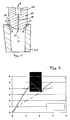
- FIG. 1 shows such a known arrangement, wherein the plug 10 and a corresponding spout carries the reference numeral 50.
- the illustrated lower (second) end 14 of the plug 10 is in a slightly raised position, so that between the plug 10 and spout 50 an annular channel is formed by the melt S from a tundish, not shown in the spout 50 and from there into downstream facilities can flow.
- the treatment gas which is supplied via the opening 16 and passed from there in the direction of arrow G in the gas channel 18, which is coaxial with the central longitudinal axis M of the plug-shaped body 10, leaves the plug 10 in the region of a spout opening 20 at the lowermost part of the second end 14 and flows from there into the melt S.
- a control valve of the type shown has long been used. However, it has been found that irregularities in the flow behavior of the melt occur again and again during operation.
- a closure plug in which a filling body extends over a part of the opening, viewed in the axial direction of the body, wherein at least one gas channel runs through the filling body or between filling body and body in the axial direction of the filling body, parallel to the central longitudinal axis of the sealing plug or spirally helical or meandering or threading which fluidly connects the opening to the gas channel which transports the gas to the surface of the second end of the plug.
- the invention has for its object to optimize a generic plug so far that even with different positioning of the plug relative to the spout a controlled melt flow is achieved.
- the invention is based on the following finding:
- the flow rate (m 3 / h) is plotted on the abscissa versus the gap width between the second end (nose) of a plug and the associated spout on the ordinate, corresponding to one device FIG. 1 ,
- the dashed line schematically characterizes the dependence in an application in which no gas flows, while the closed line characterizes the dependence of the two parameters under gas supply.
- the said section has a so-called Restrictor function, as it basically from the already mentioned DE 10 2005 029 033 B4 known is. While there is a relatively low gas pressure above this section, the reduced flow cross section for the gas in the region of the section leads to a significant increase in the gas pressure and the gas velocity, which subsequently decrease again with an increased flow cross section.
- the gap width between plug and spout can be controlled so that the casting process outside the discontinuity range, as in FIG. 2 shown, takes place.
- plug and spout are arranged in a corresponding manner to each other depending on the amount and the pressure of the supplied gas. If, for example, the casting performance has to be reduced due to operational reasons or if it is reduced by metallurgical influences such as buildup in a dip tube, which follows the pouring fluidically, there is a risk that it will enter the discontinuity zone and increase the casting volume despite reducing the gap width between the stopper and the spout , This case is indicated by pressure fluctuations in the connection area of the plug because too much gas enters the reduced melt flow. This phenomenon is now used for the early detection of the changed flow pattern. By reducing the gas pressure in the connection area, the plug lowers slightly in the direction of the Spout, the gap width decreases and the melt flow decreases as desired.
- the device for measuring the gas pressure can be arranged directly in said region of the opening, for example in the form of a manometer, in particular an electronic pressure gauge, which withstands the temperatures prevailing there (about 1,500 to 1,600 ° C).
- the transmission of the pressure measured values to an evaluation unit can take place via temperature-resistant cables or wirelessly, for example by radio.
- connection area of the Opening connects with a pressure gauge.
- the actual pressure gauge can also be arranged outside the plug, in particular in a region in which lower ambient temperatures prevail, that is, for example, in the region of said lifting device for raising and lowering the plug.
- the same gas pressure prevails in the measuring channel as in the connection area of the opening so that it can be measured exactly.
- the measuring channel from the connection region of the opening at least partially lead through the body in the direction of the first end.
- the measuring channel is then led out of the body, for example, above the molten bath and guided via a connecting line to the pressure measuring device.
- the mentioned Restrictor section can be formed in different ways.
- One possibility is to arrange the section in the opening itself.
- the section may be stationary by one in the opening arranged filling body are formed, wherein at least one gas passage between the filler body and a corresponding wall of the opening remains free.
- the portion is formed by a packing arranged in a stationary manner in the opening, which extends over the entire cross-section of the opening, wherein at least one gas passage extends through the packing, which directs a gas flowing therethrough in the direction of the connection area of the opening.
- Another way to form the section consists of a filling body which extends over the entire cross-section of the opening and divides the opening into two areas in the axial direction, and with a channel which connects one area of the opening with the other area of the opening and a cross section smaller than the cross section of each region of the opening.
- the channel extends, for example, through the plug body with inlet and outlet openings in the wall of the opening.
- These gas passages each have a cross section which is smaller than the cross section of the opening.
- the ratio is at least 1: 5 or at least 1:10, but it may also be higher.
- the opening diameter is for example 15 to 30 mm and that of the gas channels with reduced cross-section between 2 and 7 mm.
- the at least one gas channel which leads to the surface portion in the region of the second end of the body
- this may be a single, discrete gas channel extending, for example, coaxially to the central longitudinal axis of the plug.
- it can also be arranged several juxtaposed gas channels with a correspondingly small flow cross-section.
- Another possibility is to do so said nose portion (the second end) of the plug at least partially with an undirected porosity, that is, the gas does not flow linearly from the opening to the plug surface, as in a channel, but zigzagged according to the open porosity in this end portion of the plug.
- the plug according to FIG. 3 consists of a refractory ceramic body 10.
- an opening 16 extends from a first end 12 to a second end 14 and thus from a supply region 22 for a treatment gas to a connection region 24 with a bottom 26th
- a gas channel 18 extends to the surface portion 20 of the body 10 in the region of the second end 14.
- the gas channel 18 has a cross-sectional area which is about 1/10 of the cross-sectional area of the opening 16.
- a filler 30 is provided which forms a portion through which the opening 16 is divided into an upper portion 32 and a lower portion 34.
- the filler body 30 extends over the entire cross-sectional area of the opening 16 and has a central passage opening 36 which connects the sections 32, 34 with each other.
- the flow cross section of the passage opening 36 is clear smaller than the cross section of the opening 16.
- the section 30 forms a kind Restrictor.
- the plug is formed with a device 40 that includes a gas line 42 and a pressure gauge 44.
- the gas conduit 42 extends from a wall 38 of the region 34, then extends toward the first end 12 through the body 10, and then exits the body 10 to the outside and continues in a gas conduit leading to the manometer 44.
- the gas pressure in the region 34 of the plug can be measured continuously.
- a signal can be generated via a corresponding computer program in order to raise or lower the plug relative to the spout and to regulate the flow rate of the melt.
- the embodiment according to FIG. 4 differs from the embodiment according to FIG. 3 in that the section (filling body) 30 completely separates the section 32 from the section 34 in terms of flow technology.
- the gas flows in this case from the region 32 via a bypass 36 'within the body 10 in the region 34, wherein the flow cross-section of the bypass 36' about the gas passage 36 in the embodiment after FIG. 3 equivalent.
- a membrane manometer 44 ' is arranged, which is part of the device for measuring the gas pressure in the region 34.
- the membrane manometer 44 ' comprises a high-temperature-resistant, gas-permeable metal membrane, which bulges differently depending on the gas pressure.
- the thereby accomplished path change is via a measuring line 42 'in an evaluation 46 and converted into corresponding gas pressure values. As described, the respective value gives the steelworker an indication to throttle or increase the flow rate of the molten steel in order not to enter the critical zone ( FIG. 2 ) get.
- the embodiment according to FIG. 5 basically corresponds to the according DE 10 2005 029 033 B4 with the proviso that in the, here very small area 34 between portion (packing) 30 and bottom 26, an electronic pressure gauge 44 "is arranged, from which a measuring line 42" leads to an evaluation unit 46, wherein the measuring line 42 partially through the Body 10 of the plug extends.
- the pressure gauge 44 or the evaluation units 46 are arranged in a region in which the temperatures are as low as possible, ie outside the molten bath.
Landscapes
- Engineering & Computer Science (AREA)
- Mechanical Engineering (AREA)
- Treatment Of Steel In Its Molten State (AREA)
- Furnace Charging Or Discharging (AREA)
- Measuring Fluid Pressure (AREA)
- Casting Support Devices, Ladles, And Melt Control Thereby (AREA)
- Fireproofing Substances (AREA)
- Control Of Motors That Do Not Use Commutators (AREA)
- Secondary Cells (AREA)
- Spark Plugs (AREA)
- Ceramic Products (AREA)
Abstract
Description
- Die Erfindung betrifft einen feuerfesten keramischen Stopfen zur Regelung einer vorbeiströmenden Metallschmelze im Bereich einer Auslassöffnung eines metallurgischen Schmelzgefäßes, beispielsweise eines Tundish.
- Ein solcher Stopfen ist üblicherweise wie folgt aufgebaut: Er weist einen stabförmigen Körper mit einem ersten Ende und einem zweiten Ende auf, wobei der Körper aus mindestens einem feuerfesten keramischen Werkstoff besteht. Stabförmig ist im technischen Sinne zu verstehen, das heißt, die Länge des Körpers ist sehr viel größer als sein Durchmesser/seine Breite. Vom ersten Ende des Körpers erstreckt sich eine sackartige Öffnung in Axialrichtung des Körpers auf das zweite Ende hin, wobei diese Öffnung bis zu einem Anschlussbereich mit einem Boden reicht und der Anschlussbereich vor dem zweiten Ende des Körpers endet. Am ersten Ende des Körpers ist ein so genannter Zuführbereich vorgesehen, weil hier ein Behandlungsgas, insbesondere ein Inertgas, wie Argon, in die Öffnung des Stopfens eingeleitet wird.
- Um das Gas, welches die Öffnung durchströmt, aus dem Bereich des zweiten Endes des Körpers in eine Metallschmelze einzuleiten, verläuft vom Anschlussbereich der Öffnung mindestens ein Gaskanal bis zu einem Oberflächenabschnitt des Körpers im Bereich seines zweiten Endes. Dieser Gaskanal hat eine Querschnittsfläche, die kleiner ist als die Querschnittsfläche der Öffnung.
- Der Stopfen wird unmittelbar im Ausgussbereich des metallurgischen Schmelzgefäßes angeordnet, und zwar in vertikaler Ausrichtung mit dem ersten Ende oben und dem zweiten Ende unten, dem Ausguss benachbart. Durch Heben und Senken des Stopfens kann ein Ringkanal gegenüber dem Ausguss vergrößert oder verkleinert werden, um die Menge der hindurch geführten/vorbeiströmenden Metallschmelze zu regeln.
-
Figur 1 zeigt eine solche bekannte Anordnung, wobei der Stopfen das Bezugszeichen 10 und ein zugehöriger Ausguss das Bezugszeichen 50 trägt. Das dargestellte untere (zweite) Ende 14 des Stopfens 10 befindet sich in leicht angehobener Stellung, so dass zwischen Stopfen 10 und Ausguss 50 ein Ringkanal ausgebildet wird, durch den Schmelze S aus einem nicht dargestellten Tundish in den Ausguss 50 und von dort in nachgeordnete Einrichtungen fließen kann. - Das Behandlungsgas, welches über die Öffnung 16 zugeführt und von dort in Pfeilrichtung G in den Gaskanal 18 geleitet wird, der koaxial zur Mittenlängsachse M des stopfenförmigen Körpers 10 verläuft, verlässt den Stopfen 10 im Bereich einer Ausgussöffnung 20 am untersten Teil des zweiten Endes 14 und strömt von dort in die Schmelze S.
- Zum Heben und Senken des Stopfens 10 ist es bekannt, im Bereich der Öffnung 16 ein Metallgestänge zu befestigen, welches mit seinem aus dem Stopfen 16 nach oben vorstehenden Abschnitt an einer entsprechenden Hubeinrichtung befestigt ist.
- Soweit im Rahmen dieser Anmeldung von oben und unten gesprochen wird, beziehen sich diese Angaben auf die Funktionsposition des Stopfens 10.
- Ein Regelventil der dargestellten Art wird seit langem eingesetzt. Es hat sich jedoch herausgestellt, dass es im Betrieb immer wieder zu Unregelmäßigkeiten im Strömungsverhalten der Schmelze kommt.
- Dies hängt unter anderem mit dem Transport und der Zuführung des Gases zusammen.
- Aus der
DE 10 2005 029 033 B4 ist ein Verschlussstopfen bekannt, bei dem sich ein Füllkörper über einen Teil der Öffnung - in Axialrichtung des Körpers betrachtet - erstreckt, wobei durch den Füllkörper oder zwischen Füllkörper und Körper mindestens ein Gaskanal in Axialrichtung des Füllkörpers verläuft, parallel zur Mittenlängsachse des Verschlussstopfens oder spiral-, schraubenlinien- oder mäanderförmig oder gewindeartig, der die Öffnung mit dem Gaskanal strömungstechnisch verbindet, der das Gas an die Oberfläche des zweiten Endes des Stopfens transportiert. - Auf diese Weise wird ein Mittel zur Einstellung des Gas-Strömungswiderstandes geschaffen.
- Der Erfindung liegt die Aufgabe zugrunde, einen gattungsgemäßen Stopfen insoweit zu optimieren, dass auch bei unterschiedlicher Positionierung des Stopfens gegenüber dem Ausguss ein kontrollierter Schmelzefluss erreicht wird.
- In
Figur 2 ist die Durchflussrate (m3/h) auf der Abszisse gegenüber der Spaltbreite zwischen dem zweiten Ende (der Nase) eines Stopfens und dem zugehörigen Ausguss auf der Ordinate aufgetragen, und zwar für eine Einrichtung entsprechendFigur 1 . - Die gestrichelte Linie charakterisiert schematisch die Abhängigkeit bei einem Anwendungsfall, bei dem kein Gas strömt, während die geschlossene Linie die Abhängigkeit der beiden Kenngrößen unter Gaszufuhr charakterisiert.
- Während ohne Gas eine nahezu lineare Abhängigkeit zwischen der Öffnungsweite und der hindurch geführten Schmelzemenge besteht, ist eine auffällige Unstetigkeit im Fall der Zuleitung eines Behandlungsgases zu erkennen. In diesem Unstetigkeitsbereich kommt es zu Gießstörungen mit möglichen Fehlern am Endprodukt.
- Während bei geringer Öffnungsweite wiederum eine nahezu lineare Abhängigkeit zur korrespondierenden Schmelzemenge besteht, kommt es in dem dunkel unterlegten Bereich zu Unstetigkeiten. An diesen Unstetigkeitsbereich schließt sich wiederum ein nahezu linearer Verlauf an. Die links der Unstetigkeitsstelle dargestellte Strömung wird als Propfenströmung (slug flow) und die rechts der Unstetigkeitsstelle dargestellte Strömung als Blasenströmung (bubbly flow) bezeichnet.
- Es ist offensichtlich, dass eine Stranggießanlage nur dann optimal betrieben werden kann, wenn man außerhalb des in
Figur 2 dargestellten Unstetigkeitsbereiches liegt. Nur dann kann durch Veränderung der Spaltweite eine gezielte Veränderung der Schmelzeflusses hinsichtlich Menge und Strömungsverlauf erreicht werden. - An dieser Stelle greift der Erfindungsgedanke ein.
- Ein erfindungsgemäßer feuerfester keramischer Stopfen zur Regelung einer vorbeiströmenden Metallschmelze weist folgende Merkmale auf:
- einen stabförmigen Körper mit einem ersten Ende und einem zweiten Ende,
- vom ersten Ende des Körpers erstreckt sich eine sackartige Öffnung von einem Zuführbereich in Axialrichtung des Körpers bis zu einem Anschlussbereich mit einem Boden,
- vom Anschlussbereich der Öffnung verläuft mindestens ein Gaskanal bis zu einem Oberflächenabschnitt des Körpers im Bereich eines zweiten Endes,
- der Gaskanal hat eine Querschnittsfläche, die kleiner ist als die Querschnittsfläche der Öffnung,
- entlang der Öffnung ist mindestens ein Abschnitt vorgesehen, durch den ein vom Zuführbereich zum Anschlussbereich gefördertes Gas zwangsweise hindurchgeführt wird, wobei der Abschnitt einen wirksamen Strömungsquerschnitt aufweist, der kleiner ist als der der Öffnung,
- im Bereich der Öffnung zwischen dem Boden und dem dem Boden benachbarten Abschnitt ist eine Einrichtung zur Messung des Gasdrucks in diesem Bereich angeordnet oder angeschlossen.
- Der genannte Abschnitt hat eine so genannte Restrictor-Funktion, wie sie grundsätzlich aus der bereits erwähnten
DE 10 2005 029 033 B4 bekannt ist. Während oberhalb dieses Abschnitts ein relativ geringer Gasdruck herrscht, führt der verminderte Strömungsquerschnitt für das Gas im Bereich des Abschnittes zu einer deutlichen Erhöhung des Gasdrucks und der Gasgeschwindigkeit, die sich im Anschluss daran bei vergrößertem Strömungsquerschnitt wieder verringern. - Durch die vorbeiströmende Metallschmelze entstehen je nach Öffnungsweite zwischen Stopfen und Ausguss unterschiedliche Druckverhältnisse in der Schmelze, wodurch ein unterschiedlicher Unterdruck auf das zugeführte Gas einwirkt.
- Mit der Einrichtung zur Messung des Gasdrucks im Anschlussbereich der Öffnung kann mit einem erfindungsgemäßen Stopfen der exakte Druck des Gases, welches den Stopfen verlässt, zu jeder Zeit festgestellt werden. Entsprechend kann in Kenntnis dieser Druck-Messgröße die Spaltweite zwischen Stopfen und Ausguss so geregelt werden, dass der Gießvorgang außerhalb des Unstetigkeitsbereiches, wie in
Figur 2 dargestellt, erfolgt. - Dies soll an einem Beispiel erläutert werden: Beim Gießen wird regelmäßig eine Blasenströmung angestrebt. Dazu werden Stopfen und Ausguss in Abhängigkeit von der Menge und dem Druck des zugeführten Gases in entsprechender Weise zueinander angeordnet. Muss zum Beispiel betriebsbedingt die Gießleistung reduziert werden oder reduziert sie sich durch metallurgische Einflüsse wie Ansatzbildung in einem Tauchrohr, welches dem Ausguss strömungstechnisch folgt, besteht die Gefahr, dass man in den Unstetigkeitsbereich gelangt und trotz Verringerung der Spaltbreite zwischen Stopfen und Ausguss die Gießmenge erhöht wird. Dieser Fall wird durch Druckschwankungen im Anschlussbereich des Stopfens angezeigt, weil zuviel Gas in den reduzierten Schmelzefluss gelangt. Dieses Phänomen wird nun zur Früherkennung des veränderten Strömungsbildes herangezogen. Durch Reduzierung des Gasdrucks im Anschlussbereich senkt sich der Stopfen etwas in Richtung auf den Ausguss, die Spaltbreite verringert sich und der Schmelzestrom sinkt, wie gewünscht.
- Die Einrichtung zur Messung des Gasdrucks kann direkt in dem genannten Bereich der Öffnung angeordnet werden, beispielsweise in Form eines Manometers, insbesondere eines elektronischen Druckmessgerätes, welches den dort herrschenden Temperaturen (ca. 1.500 bis 1.600° C) standhält. Die Übertragung der Druck-Messwerte an eine Auswerteeinheit kann über temperaturbeständige Kabel oder drahtlos, zum Beispiel per Funk erfolgen.
- Aufgrund dieser hohen Temperaturen und des nur geringen Raumes, der im Öffnungsbereich zur Anordnung des Messgerätes zur Verfügung steht, sieht eine alternative Ausführungsform der Erfindung vor, im Bereich der Öffnung zwischen dem Boden und dem dem Boden benachbarten Abschnitt einen Messkanal anzuordnen, der den Anschlussbereich der Öffnung mit einem Druckmessgerät verbindet. Auf diese Weise kann das eigentliche Druckmessgerät auch außerhalb des Stopfens angeordnet werden, insbesondere in einem Bereich, bei dem geringere Umgebungstemperaturen herrschen, also beispielsweise im Bereich der genannten Hubeinrichtung zum Heben und Senken des Stopfens. Im Messkanal herrscht der gleiche Gasdruck wie im Anschlussbereich der Öffnung, so dass dieser exakt gemessen werden kann.
- Dabei kann der Messkanal vom Anschlussbereich der Öffnung zumindest abschnittweise durch den Körper in Richtung auf dessen erstes Ende führen. Der Messkanal wird dann beispielsweise oberhalb des Schmelzbades aus dem Körper herausgeführt und über eine Anschlussleitung zum Druckmessgerät geführt.
- Der genannte Restrictor-Abschnitt lässt sich auf unterschiedliche Art und Weise ausbilden. Eine Möglichkeit ist, den Abschnitt in der Öffnung selbst anzuordnen. Dazu kann der Abschnitt von einem in der Öffnung stationär angeordneten Füllkörper gebildet werden, wobei mindestens ein Gasdurchlass zwischen dem Füllkörper und einer korrespondierenden Wand der Öffnung frei bleibt.
- Nach einer alternativen Ausführungsform wird der Abschnitt von einem in der Öffnung stationär angeordneten Füllkörper gebildet, der sich über den gesamten Querschnitt der Öffnung erstreckt, wobei mindestens ein Gasdurchlass durch den Füllkörper verläuft, der ein hindurchströmendes Gas in Richtung auf den Anschlussbereich der Öffnung leitet.
- Eine weitere Möglichkeit, den Abschnitt auszubilden, besteht in einem Füllkörper, der sich über den gesamten Querschnitt der Öffnung erstreckt und die Öffnung in Axialrichtung in zwei Bereiche teilt, sowie mit einem Kanal, der den einen Bereich der Öffnung mit dem anderen Bereich der Öffnung verbindet und einen Querschnitt aufweist, der kleiner ist als der Querschnitt jedes Bereiches der Öffnung. Der Kanal verläuft beispielsweise durch den Stopfenkörper mit Eingangs- und Ausgangsöffnung in der Wand der Öffnung.
- Diese Gasdurchlässe weisen jeweils einen Querschnitt auf, der kleiner ist als der Querschnitt der Öffnung. Beispielsweise beträgt das Verhältnis mindestens 1 : 5 oder mindestens 1 : 10, es kann aber auch darüber liegen. Absolut beträgt der Öffnungsdurchmesser zum Beispiel 15 bis 30mm und der der Gaskanäle mit verringertem Querschnitt zwischen 2 und 7mm.
- Für den mindestens einen Gaskanal, der zum Oberflächenabschnitt im Bereich des zweiten Endes des Körpers führt, gilt, dass dies ein einzelner, diskreter Gaskanal sein kann, der beispielsweise koaxial zur Mittenlängsachse des Stopfens verläuft. Es können aber auch mehrere, nebeneinander angeordnete Gaskanäle mit entsprechend kleinem Strömungsquerschnitt angeordnet werden. Eine weitere Möglichkeit besteht darin, den so genannten Nasenabschnitt (das zweite Ende) des Stopfens zumindest teilweise mit einer ungerichteten Porosität auszubilden, das heißt, dass das Gas nicht linear von der Öffnung zur Stopfenoberfläche strömt, wie in einem Kanal, sondern zickzackartig entsprechend der offenen Porosität in diesem Endabschnitt des Stopfens.
- Weitere Merkmale der Erfindung ergeben sich aus den Merkmalen der Unteransprüche sowie den sonstigen Anmeldungsunterlagen.
- Die Erfindung wird nachstehend anhand von drei Ausführungsbeispielen näher erläutert. Dabei sind jeweils in schematisierter Darstellung Längsschnitte durch Ausführungsformen eines erfindungsgemäßen Stopfens dargestellt. Gleiche oder gleich wirkende Bauteile werden durch gleiche Bezugsziffern erläutert.
- Der Stopfen gemäß
Figur 3 besteht aus einem feuerfesten keramischen Körper 10. In Axialrichtung des Stopfens verläuft eine Öffnung 16 von einem ersten Ende 12 bis zu einem zweiten Ende 14 und damit von einem Zuführbereich 22 für ein Behandlungsgas bis zu einem Anschlussbereich 24 mit einem Boden 26. - Vom Anschlussbereich 24 der Öffnung 16 verläuft ein Gaskanal 18 bis zum Oberflächenabschnitt 20 des Körpers 10 im Bereich des zweiten Endes 14. Der Gaskanal 18 hat eine Querschnittsfläche, die etwa 1/10 der Querschnittsfläche der Öffnung 16 beträgt.
- Entlang der Öffnung 16 ist ein Füllkörper 30 vorgesehen, der einen Abschnitt bildet, durch den die Öffnung 16 in einen oberen Bereich 32 und einen unteren Bereich 34 unterteilt wird. Der Füllkörper 30 erstreckt sich über die gesamte Querschnittsfläche der Öffnung 16 und weist eine mittige Durchgangsöffnung 36 auf, die die Abschnitte 32, 34 miteinander verbindet. Der Strömungsquerschnitt der Durchgangsöffnung 36 ist deutlich kleiner als der Querschnitt der Öffnung 16. Der Abschnitt 30 bildet eine Art Restrictor.
- Der Stopfen ist mit einer Einrichtung 40 ausgebildet, die eine Gasleitung 42 und ein Manometer 44 umfasst. Die Gasleitung 42 erstreckt sich von einer Wand 38 des Bereiches 34, verläuft dann in Richtung auf das erste Ende 12 durch den Körper 10, um dann den Körper 10 nach außen zu verlassen und sich in einer Gasleitung fortzusetzen, die bis zum Manometer 44 führt.
- Mit dem Manometer 44 lässt sich der Gasdruck im Bereich 34 des Stopfens, also in dem Bereich unterhalb des Füllkörpers 30, kontinuierlich messen. Je nachdem, ob der im jeweiligen Anwendungsfall gemessene Gasdruck zu hoch oder zu niedrig ist, kann über ein entsprechendes Rechenprogramm ein Signal erzeugt werden, um den Stopfen gegenüber dem Ausguss anzuheben oder abzusenken und die Strömungsmenge der Schmelze zu regulieren.
- Das Ausführungsbeispiel nach
Figur 4 unterscheidet sich vom Ausführungsbeispiel nachFigur 3 dadurch, dass der Abschnitt (Füllkörper) 30 den Abschnitt 32 strömungstechnisch vollständig vom Abschnitt 34 trennt. Das Gas strömt in diesem Fall vom Bereich 32 über einen Bypass 36' innerhalb des Körpers 10 in den Bereich 34, wobei der Strömungsquerschnitt des Bypasses 36' etwa dem des Gasdurchlasses 36 beim Ausführungsbeispiel nachFigur 3 entspricht. - Im Bereich 34, also zwischen dem Boden 26 und dem Abschnitt 30 ist ein Membranmanometer 44' angeordnet, welches Bestandteil der Einrichtung zur Messung des Gasdrucks im Bereich 34 ist. Das Membranmanometer 44' umfasst eine hochtemperaturbeständige, gasdurchlässige Metallmembran, die sich je nach Gasdruck unterschiedlich aufwölbt. Die dabei vollzogene Wegveränderung wird über eine Messleitung 42' in einer Auswerteeinheit 46 erfasst und in entsprechende Gas-Druckwerte umgerechnet. Wie beschrieben gibt der jeweilige Wert dem Stahlwerker einen Hinweis, die Strömungsmenge der Stahlschmelze zu drosseln oder zu erhöhen, um nicht in die kritische Zone (
Figur 2 ) zu kommen. - Die Ausführungsform nach
Figur 5 entspricht grundsätzlich der gemäßDE 10 2005 029 033 B4 mit der Maßgabe, dass in dem, hier sehr kleinen Bereich 34 zwischen Abschnitt (Füllkörper) 30 und Boden 26 ein elektronisches Druckmessgerät 44" angeordnet ist, von dem eine Messleitung 42" zu einer Auswerteeinheit 46 führt, wobei sich die Messleitung 42 teilweise durch den Körper 10 des Stopfens erstreckt. - Anstelle der Übertragung der Messwerte per Kabel kann auch eine drahtlose Übermittlung zum Beispiel per Funk vorgesehen werden.
- Es ist selbstverständlich, dass das Manometer 44 beziehungsweise die Auswerteeinheiten 46 in einem Bereich angeordnet werden, bei dem möglichst geringe Temperaturen herrschen, also außerhalb des Schmelzbades.
Claims (12)
- Feuerfester keramischer Stopfen zur Regelung einer
vorbeiströmenden Metallschmelze, mit folgenden Merkmalen:1.1 einem stabförmigen Körper (10) mit einem ersten Ende (12) und einem zweiten Ende (14),1.2 vom ersten Ende (12) des Körpers (10) erstreckt sich eine sackartige Öffnung (16) von einem Zuführbereich (22) in Axialrichtung des Körpers (10) bis zu einem Anschlussbereich (24) mit einem Boden (26),1.3 vom Anschlussbereich (24) der Öffnung (16) verläuft mindestens ein Gaskanal (18) bis zu einem Oberflächenabschnitt (20) des Körpers (10) im Bereich seines zweiten Endes (14),1.4 der Gaskanal (18) hat eine Querschnittsfläche, die kleiner ist als die Querschnittsfläche der Öffnung (16),1.5 entlang der Öffnung (16) ist mindestens ein Abschnitt (30) vorgesehen, durch den ein vom Zuführbereich (22) zum Anschlussbereich (24) gefördertes Gas zwangsweise hindurchgeführt wird, wobei der Abschnitt (30) einen wirksamen Strömungsquerschnitt aufweist, der kleiner ist als der der Öffnung (16),1.6 im Bereich der Öffnung (16) zwischen dem Boden (26) und dem dem Boden (26) benachbarten Abschnitt (30) ist eine Einrichtung (40) zur Messung des Gasdrucks in diesem Bereich (34) angeordnet oder angeschlossen. - Stopfen nach Anspruch 1, mit einem koaxial zur Öffnung (16) verlaufenden Gaskanal (18).
- Stopfen nach Anspruch 1, dessen Abschnitt (30) in der Öffnung (16) liegt.
- Stopfen nach Anspruch 1, dessen Abschnitt (30) von einem in der Öffnung (16) stationär angeordneten Füllkörper gebildet wird, wobei mindestens ein Gasdurchlass zwischen dem Füllkörper und einer korrespondierenden Wand (38) der Öffnung (16) frei bleibt.
- Stopfen nach Anspruch 1, dessen Abschnitt (30) von einem in der Öffnung (16) stationär angeordneten Füllkörper gebildet wird, der sich über den gesamten Querschnitt der Öffnung (16) erstreckt, wobei mindestens ein Gasdurchlass (36) durch den Füllkörper verläuft, der ein hindurchströmendes Gas in Richtung auf den Anschlussbereich (24) der Öffnung (16) leitet.
- Stopfen nach Anspruch 1, mit einem Füllkörper (30), der sich über den gesamten Querschnitt der Öffnung (16) erstreckt und die Öffnung (16) in Axialrichtung in zwei Bereiche (32, 34) teilt, sowie mit einem Kanal (36'), der den einen Bereich (32) der Öffnung (16) mit dem anderen Bereich (34) der Öffnung (16) verbindet und einen Querschnitt aufweist, der kleiner ist als der Querschnitt jedes Bereiches (32, 34) der Öffnung (16).
- Stopfen nach Anspruch 1, dessen Einrichtung (40) zur Messung des Gasdrucks ein Manometer (44) umfasst.
- Stopfen nach Anspruch 1, dessen Einrichtung (40) zur Messung des Gasdrucks einen Messkanal (42) umfasst, der den Anschlussbereich (34) der Öffnung (16) mit einem Druckmessgerät (44) verbindet.
- Stopfen nach Anspruch 8, dessen Messkanal (42) vom Anschlussbereich (34) zumindest abschnittweise durch den Körper (10) in Richtung auf dessen erstes Ende (12) führt.
- Stopfen nach Anspruch 1, dessen Einrichtung (40) zur Messung des Gasdrucks ein im Anschlussbereich (34) angeordnetes Druckmessgerät (44', 44") umfasst.
- Stopfen nach Anspruch 1, dessen Einrichtung (40) zur Messung des Gasdrucks ein Membranmanometer (44') aufweist.
- Stopfen nach Anspruch 1, dessen Einrichtung (40) zur Messung des Gasdrucks ein elektronisches Druckmessgerät (44") aufweist.
Priority Applications (11)
| Application Number | Priority Date | Filing Date | Title |
|---|---|---|---|
| DE502009000331T DE502009000331D1 (de) | 2009-03-23 | 2009-03-23 | Feuerfester keramischer Stopfen |
| AT09004143T ATE495840T1 (de) | 2009-03-23 | 2009-03-23 | Feuerfester keramischer stopfen |
| EP09004143A EP2233227B1 (de) | 2009-03-23 | 2009-03-23 | Feuerfester keramischer Stopfen |
| PL09004143T PL2233227T3 (pl) | 2009-03-23 | 2009-03-23 | Ogniotrwała zatyczka ceramiczna |
| CN2010800177374A CN102413962A (zh) | 2009-03-23 | 2010-02-13 | 耐火陶瓷塞 |
| BRPI1010013A BRPI1010013A2 (pt) | 2009-03-23 | 2010-02-13 | plugue cerâmico refratário |
| US13/257,253 US20120001372A1 (en) | 2009-03-23 | 2010-02-13 | Refractory ceramic plug |
| PCT/EP2010/000895 WO2010108572A1 (de) | 2009-03-23 | 2010-02-13 | Feuerfester keramischer stopfen |
| MX2011009905A MX2011009905A (es) | 2009-03-23 | 2010-02-13 | Tapon ceramico refractario. |
| RU2011138684/02A RU2488461C2 (ru) | 2009-03-23 | 2010-02-13 | Огнеупорная керамическая пробка |
| TW099107981A TW201034772A (en) | 2009-03-23 | 2010-03-18 | Refractory ceramic plug |
Applications Claiming Priority (1)
| Application Number | Priority Date | Filing Date | Title |
|---|---|---|---|
| EP09004143A EP2233227B1 (de) | 2009-03-23 | 2009-03-23 | Feuerfester keramischer Stopfen |
Publications (2)
| Publication Number | Publication Date |
|---|---|
| EP2233227A1 true EP2233227A1 (de) | 2010-09-29 |
| EP2233227B1 EP2233227B1 (de) | 2011-01-19 |
Family
ID=40622516
Family Applications (1)
| Application Number | Title | Priority Date | Filing Date |
|---|---|---|---|
| EP09004143A Not-in-force EP2233227B1 (de) | 2009-03-23 | 2009-03-23 | Feuerfester keramischer Stopfen |
Country Status (11)
| Country | Link |
|---|---|
| US (1) | US20120001372A1 (de) |
| EP (1) | EP2233227B1 (de) |
| CN (1) | CN102413962A (de) |
| AT (1) | ATE495840T1 (de) |
| BR (1) | BRPI1010013A2 (de) |
| DE (1) | DE502009000331D1 (de) |
| MX (1) | MX2011009905A (de) |
| PL (1) | PL2233227T3 (de) |
| RU (1) | RU2488461C2 (de) |
| TW (1) | TW201034772A (de) |
| WO (1) | WO2010108572A1 (de) |
Cited By (3)
| Publication number | Priority date | Publication date | Assignee | Title |
|---|---|---|---|---|
| WO2018108789A1 (en) * | 2016-12-12 | 2018-06-21 | Vesuvius Group, S.A. | Stopper equipped with an integrated slag detection device |
| EP3705204A1 (de) | 2019-03-08 | 2020-09-09 | Refractory Intellectual Property GmbH & Co. KG | Stopfenstange und verfahren zur bereitstellung eines gleichmässigen gasvorhangs um eine stopfenstange |
| WO2024017662A1 (en) | 2022-07-18 | 2024-01-25 | Refractory Intellectual Property Gmbh & Co. Kg | Stopper rod and method for inducing a rotational flow of a molten metal |
Families Citing this family (2)
| Publication number | Priority date | Publication date | Assignee | Title |
|---|---|---|---|---|
| EP2653248B1 (de) * | 2012-04-16 | 2014-04-02 | Refractory Intellectual Property GmbH & Co. KG | Feuerfester Verschlussstopfen |
| US12023730B2 (en) | 2018-12-25 | 2024-07-02 | Krosakiharima Corporation | Stopper for continuous casting and continuous casting method |
Citations (3)
| Publication number | Priority date | Publication date | Assignee | Title |
|---|---|---|---|---|
| EP0396111A2 (de) * | 1989-05-03 | 1990-11-07 | British Steel plc | Steuern eines Gussstroms |
| WO2005042183A1 (en) * | 2003-11-04 | 2005-05-12 | Mefos-Metallurgical Research Institute Ab | A method and a device for detecting slag |
| DE102005029033B4 (de) | 2005-06-21 | 2007-10-11 | Refractory Intellectual Property Gmbh & Co. Kg | Verschlussstopfen für ein metallurgisches Schmelzgefäß |
Family Cites Families (7)
| Publication number | Priority date | Publication date | Assignee | Title |
|---|---|---|---|---|
| GB8411596D0 (en) * | 1984-05-05 | 1984-06-13 | Thor Ceramics Ltd | Stopper |
| DE4142773A1 (de) * | 1991-12-23 | 1993-06-24 | Thyssen Stahl Ag | Stopfen fuer metallurgische gefaesse |
| CN1267219C (zh) * | 2001-06-08 | 2006-08-02 | 维苏维尤斯·克鲁斯布公司 | 塞棒 |
| CA2447072C (en) * | 2001-06-12 | 2010-08-10 | Vesuvius Crucible Company | Stopper for reliable gas injection |
| CN1301167C (zh) * | 2003-06-02 | 2007-02-21 | 北京科技大学 | 一种在中间包钢液中产生弥散微小气泡的方法 |
| CN100467165C (zh) * | 2006-04-14 | 2009-03-11 | 广东韶钢松山股份有限公司 | 连铸中间包浸入式水口的烘烤方法 |
| ES2351075T3 (es) * | 2008-11-19 | 2011-01-31 | REFRACTORY INTELLECTUAL PROPERTY GMBH & CO. KG | Cuerpo de tapón. |
-
2009
- 2009-03-23 PL PL09004143T patent/PL2233227T3/pl unknown
- 2009-03-23 AT AT09004143T patent/ATE495840T1/de active
- 2009-03-23 DE DE502009000331T patent/DE502009000331D1/de active Active
- 2009-03-23 EP EP09004143A patent/EP2233227B1/de not_active Not-in-force
-
2010
- 2010-02-13 RU RU2011138684/02A patent/RU2488461C2/ru not_active IP Right Cessation
- 2010-02-13 BR BRPI1010013A patent/BRPI1010013A2/pt not_active IP Right Cessation
- 2010-02-13 CN CN2010800177374A patent/CN102413962A/zh active Pending
- 2010-02-13 US US13/257,253 patent/US20120001372A1/en not_active Abandoned
- 2010-02-13 WO PCT/EP2010/000895 patent/WO2010108572A1/de not_active Ceased
- 2010-02-13 MX MX2011009905A patent/MX2011009905A/es active IP Right Grant
- 2010-03-18 TW TW099107981A patent/TW201034772A/zh unknown
Patent Citations (3)
| Publication number | Priority date | Publication date | Assignee | Title |
|---|---|---|---|---|
| EP0396111A2 (de) * | 1989-05-03 | 1990-11-07 | British Steel plc | Steuern eines Gussstroms |
| WO2005042183A1 (en) * | 2003-11-04 | 2005-05-12 | Mefos-Metallurgical Research Institute Ab | A method and a device for detecting slag |
| DE102005029033B4 (de) | 2005-06-21 | 2007-10-11 | Refractory Intellectual Property Gmbh & Co. Kg | Verschlussstopfen für ein metallurgisches Schmelzgefäß |
Cited By (5)
| Publication number | Priority date | Publication date | Assignee | Title |
|---|---|---|---|---|
| WO2018108789A1 (en) * | 2016-12-12 | 2018-06-21 | Vesuvius Group, S.A. | Stopper equipped with an integrated slag detection device |
| WO2018108788A1 (en) * | 2016-12-12 | 2018-06-21 | Vesuvius Group, S.A. | Stopper equipped with an integrated temperature measurement device |
| EP3705204A1 (de) | 2019-03-08 | 2020-09-09 | Refractory Intellectual Property GmbH & Co. KG | Stopfenstange und verfahren zur bereitstellung eines gleichmässigen gasvorhangs um eine stopfenstange |
| WO2020182362A1 (en) | 2019-03-08 | 2020-09-17 | Refractory Intellectual Property Gmbh & Co. Kg | A stopper rod and a method for providing a uniform gas curtain around a stopper rod |
| WO2024017662A1 (en) | 2022-07-18 | 2024-01-25 | Refractory Intellectual Property Gmbh & Co. Kg | Stopper rod and method for inducing a rotational flow of a molten metal |
Also Published As
| Publication number | Publication date |
|---|---|
| EP2233227B1 (de) | 2011-01-19 |
| US20120001372A1 (en) | 2012-01-05 |
| RU2011138684A (ru) | 2013-03-27 |
| DE502009000331D1 (de) | 2011-03-03 |
| PL2233227T3 (pl) | 2011-05-31 |
| ATE495840T1 (de) | 2011-02-15 |
| BRPI1010013A2 (pt) | 2016-04-19 |
| RU2488461C2 (ru) | 2013-07-27 |
| MX2011009905A (es) | 2012-01-20 |
| WO2010108572A1 (de) | 2010-09-30 |
| CN102413962A (zh) | 2012-04-11 |
| TW201034772A (en) | 2010-10-01 |
Similar Documents
| Publication | Publication Date | Title |
|---|---|---|
| DE69910725T2 (de) | Verbrennungsverfahren und dessen Verwendung zur Erzeugung von Glas und Metall | |
| EP2233227B1 (de) | Feuerfester keramischer Stopfen | |
| DE2842460C3 (de) | Vorrichtung zur Steuerung der Abfackelgas-Zufuhr | |
| EP2580507B1 (de) | Ventilanordnung | |
| DE2530012A1 (de) | Verfahren und vorrichtung zum kontinuierlichen zubereiten von wasser/ oelemulsionen | |
| DE69915374T2 (de) | Verfahren und vorrichtung zur regelung des druckes eines gasstromes | |
| DE102013007705B4 (de) | Vorrichtung und Verfahren zum Betreiben einer pneumatischen Förderanlage im Dichtstrom mittels gesteuerter Überström-Ventile | |
| EP1303717B1 (de) | Ventil | |
| DE69705233T2 (de) | Feuerfeste anordnungen | |
| EP2376243B1 (de) | Vorrichtung zur detektion des durchflusses und verfahren hierfür | |
| DE602005002359T2 (de) | Stopfenstange | |
| EP3672903B1 (de) | Verfahren zum befüllen von behältern mit einem füllprodukt | |
| DE2003691C3 (de) | Vorrichtung zum Prüfen des Füllgrades von Zigaretten | |
| DE2410735C3 (de) | Vorrichtung zur Regelung der Stärke der aus einer Öffnung eines Gefäßes durch ein gesteuert verschiebbares Absperrventil in eine Stranggießkokille zu vergießenden Metallschmelze | |
| EP2712691B1 (de) | Vorrichtung und Verfahren zur Sekundarkühlung in einer Gießanlage | |
| DE2107649C3 (de) | Vorrichtung zum progressiven Zuführen von Gas zum Brenner eines Warmwasserbereiters | |
| DE3522997A1 (de) | Durchflussmesser zum messen einer zeitlichen durchflussrate bei fluiden | |
| CH641324A5 (de) | Vorrichtung zur regelung des unterdruckes in einem unterdruckleitungssystem, insbesondere fuer melkanlagen. | |
| EP3041663B1 (de) | Erwärmvorrichtung zum erwärmen der ränder der einfüllöffnung einer tube | |
| DE102014012698B4 (de) | Messvorrichtung zur optischen Temperaturbestimmung eines geschmolzenen Metalls sowie Verschlussstopfen | |
| EP1893371A2 (de) | Verschlussstopfen für ein metallurgisches schmelzgefäss | |
| EP1712894B1 (de) | Partikelzähler für Fremdpartikel in einem Flüssigkeitsstrom | |
| EP3928009B1 (de) | Mischventil für eine sanitärarmatur und verfahren zur steuerung eines mischventils | |
| DE19859677C2 (de) | Vorrichtung zum Bestimmen von rheologischen Eigenschaften einer Schmelze | |
| DE102013106046A1 (de) | Ventilanordnung |
Legal Events
| Date | Code | Title | Description |
|---|---|---|---|
| PUAI | Public reference made under article 153(3) epc to a published international application that has entered the european phase |
Free format text: ORIGINAL CODE: 0009012 |
|
| 17P | Request for examination filed |
Effective date: 20091024 |
|
| AK | Designated contracting states |
Kind code of ref document: A1 Designated state(s): AT BE BG CH CY CZ DE DK EE ES FI FR GB GR HR HU IE IS IT LI LT LU LV MC MK MT NL NO PL PT RO SE SI SK TR |
|
| AX | Request for extension of the european patent |
Extension state: AL BA RS |
|
| GRAP | Despatch of communication of intention to grant a patent |
Free format text: ORIGINAL CODE: EPIDOSNIGR1 |
|
| GRAS | Grant fee paid |
Free format text: ORIGINAL CODE: EPIDOSNIGR3 |
|
| RIN1 | Information on inventor provided before grant (corrected) |
Inventor name: NITZL, GERALD Inventor name: EGLSAEER, CHRISTOPH |
|
| GRAA | (expected) grant |
Free format text: ORIGINAL CODE: 0009210 |
|
| AK | Designated contracting states |
Kind code of ref document: B1 Designated state(s): AT BE BG CH CY CZ DE DK EE ES FI FR GB GR HR HU IE IS IT LI LT LU LV MC MK MT NL NO PL PT RO SE SI SK TR |
|
| REG | Reference to a national code |
Ref country code: GB Ref legal event code: FG4D Free format text: NOT ENGLISH |
|
| REG | Reference to a national code |
Ref country code: CH Ref legal event code: EP |
|
| REG | Reference to a national code |
Ref country code: IE Ref legal event code: FG4D Free format text: LANGUAGE OF EP DOCUMENT: GERMAN |
|
| REF | Corresponds to: |
Ref document number: 502009000331 Country of ref document: DE Date of ref document: 20110303 Kind code of ref document: P |
|
| REG | Reference to a national code |
Ref country code: DE Ref legal event code: R096 Ref document number: 502009000331 Country of ref document: DE Effective date: 20110303 |
|
| REG | Reference to a national code |
Ref country code: PL Ref legal event code: T3 |
|
| AKX | Designation fees paid |
Designated state(s): AT BE BG CH CY CZ DE DK EE ES FI FR GB GR HR HU IE IS IT LI LT LU LV MC MK MT NL NO PL PT RO SE SI SK TR |
|
| REG | Reference to a national code |
Ref country code: NL Ref legal event code: VDEP Effective date: 20110119 |
|
| LTIE | Lt: invalidation of european patent or patent extension |
Effective date: 20110119 |
|
| PG25 | Lapsed in a contracting state [announced via postgrant information from national office to epo] |
Ref country code: NO Free format text: LAPSE BECAUSE OF FAILURE TO SUBMIT A TRANSLATION OF THE DESCRIPTION OR TO PAY THE FEE WITHIN THE PRESCRIBED TIME-LIMIT Effective date: 20110419 Ref country code: ES Free format text: LAPSE BECAUSE OF FAILURE TO SUBMIT A TRANSLATION OF THE DESCRIPTION OR TO PAY THE FEE WITHIN THE PRESCRIBED TIME-LIMIT Effective date: 20110430 Ref country code: LT Free format text: LAPSE BECAUSE OF FAILURE TO SUBMIT A TRANSLATION OF THE DESCRIPTION OR TO PAY THE FEE WITHIN THE PRESCRIBED TIME-LIMIT Effective date: 20110119 Ref country code: SE Free format text: LAPSE BECAUSE OF FAILURE TO SUBMIT A TRANSLATION OF THE DESCRIPTION OR TO PAY THE FEE WITHIN THE PRESCRIBED TIME-LIMIT Effective date: 20110119 Ref country code: GR Free format text: LAPSE BECAUSE OF FAILURE TO SUBMIT A TRANSLATION OF THE DESCRIPTION OR TO PAY THE FEE WITHIN THE PRESCRIBED TIME-LIMIT Effective date: 20110420 Ref country code: IS Free format text: LAPSE BECAUSE OF FAILURE TO SUBMIT A TRANSLATION OF THE DESCRIPTION OR TO PAY THE FEE WITHIN THE PRESCRIBED TIME-LIMIT Effective date: 20110519 Ref country code: HR Free format text: LAPSE BECAUSE OF FAILURE TO SUBMIT A TRANSLATION OF THE DESCRIPTION OR TO PAY THE FEE WITHIN THE PRESCRIBED TIME-LIMIT Effective date: 20110119 Ref country code: PT Free format text: LAPSE BECAUSE OF FAILURE TO SUBMIT A TRANSLATION OF THE DESCRIPTION OR TO PAY THE FEE WITHIN THE PRESCRIBED TIME-LIMIT Effective date: 20110519 Ref country code: LV Free format text: LAPSE BECAUSE OF FAILURE TO SUBMIT A TRANSLATION OF THE DESCRIPTION OR TO PAY THE FEE WITHIN THE PRESCRIBED TIME-LIMIT Effective date: 20110119 |
|
| REG | Reference to a national code |
Ref country code: IE Ref legal event code: FD4D |
|
| PG25 | Lapsed in a contracting state [announced via postgrant information from national office to epo] |
Ref country code: CY Free format text: LAPSE BECAUSE OF FAILURE TO SUBMIT A TRANSLATION OF THE DESCRIPTION OR TO PAY THE FEE WITHIN THE PRESCRIBED TIME-LIMIT Effective date: 20110119 Ref country code: FI Free format text: LAPSE BECAUSE OF FAILURE TO SUBMIT A TRANSLATION OF THE DESCRIPTION OR TO PAY THE FEE WITHIN THE PRESCRIBED TIME-LIMIT Effective date: 20110119 Ref country code: NL Free format text: LAPSE BECAUSE OF FAILURE TO SUBMIT A TRANSLATION OF THE DESCRIPTION OR TO PAY THE FEE WITHIN THE PRESCRIBED TIME-LIMIT Effective date: 20110119 Ref country code: BG Free format text: LAPSE BECAUSE OF FAILURE TO SUBMIT A TRANSLATION OF THE DESCRIPTION OR TO PAY THE FEE WITHIN THE PRESCRIBED TIME-LIMIT Effective date: 20110419 Ref country code: SI Free format text: LAPSE BECAUSE OF FAILURE TO SUBMIT A TRANSLATION OF THE DESCRIPTION OR TO PAY THE FEE WITHIN THE PRESCRIBED TIME-LIMIT Effective date: 20110119 |
|
| PG25 | Lapsed in a contracting state [announced via postgrant information from national office to epo] |
Ref country code: EE Free format text: LAPSE BECAUSE OF FAILURE TO SUBMIT A TRANSLATION OF THE DESCRIPTION OR TO PAY THE FEE WITHIN THE PRESCRIBED TIME-LIMIT Effective date: 20110119 Ref country code: MC Free format text: LAPSE BECAUSE OF NON-PAYMENT OF DUE FEES Effective date: 20110331 Ref country code: IE Free format text: LAPSE BECAUSE OF FAILURE TO SUBMIT A TRANSLATION OF THE DESCRIPTION OR TO PAY THE FEE WITHIN THE PRESCRIBED TIME-LIMIT Effective date: 20110119 Ref country code: DK Free format text: LAPSE BECAUSE OF FAILURE TO SUBMIT A TRANSLATION OF THE DESCRIPTION OR TO PAY THE FEE WITHIN THE PRESCRIBED TIME-LIMIT Effective date: 20110119 |
|
| PLBE | No opposition filed within time limit |
Free format text: ORIGINAL CODE: 0009261 |
|
| STAA | Information on the status of an ep patent application or granted ep patent |
Free format text: STATUS: NO OPPOSITION FILED WITHIN TIME LIMIT |
|
| PG25 | Lapsed in a contracting state [announced via postgrant information from national office to epo] |
Ref country code: RO Free format text: LAPSE BECAUSE OF FAILURE TO SUBMIT A TRANSLATION OF THE DESCRIPTION OR TO PAY THE FEE WITHIN THE PRESCRIBED TIME-LIMIT Effective date: 20110119 Ref country code: SK Free format text: LAPSE BECAUSE OF FAILURE TO SUBMIT A TRANSLATION OF THE DESCRIPTION OR TO PAY THE FEE WITHIN THE PRESCRIBED TIME-LIMIT Effective date: 20110119 |
|
| REG | Reference to a national code |
Ref country code: FR Ref legal event code: ST Effective date: 20111130 |
|
| 26N | No opposition filed |
Effective date: 20111020 |
|
| PG25 | Lapsed in a contracting state [announced via postgrant information from national office to epo] |
Ref country code: MT Free format text: LAPSE BECAUSE OF FAILURE TO SUBMIT A TRANSLATION OF THE DESCRIPTION OR TO PAY THE FEE WITHIN THE PRESCRIBED TIME-LIMIT Effective date: 20110119 |
|
| PG25 | Lapsed in a contracting state [announced via postgrant information from national office to epo] |
Ref country code: FR Free format text: LAPSE BECAUSE OF NON-PAYMENT OF DUE FEES Effective date: 20110331 |
|
| REG | Reference to a national code |
Ref country code: DE Ref legal event code: R097 Ref document number: 502009000331 Country of ref document: DE Effective date: 20111020 |
|
| PGFP | Annual fee paid to national office [announced via postgrant information from national office to epo] |
Ref country code: TR Payment date: 20120320 Year of fee payment: 4 |
|
| PGFP | Annual fee paid to national office [announced via postgrant information from national office to epo] |
Ref country code: IT Payment date: 20120331 Year of fee payment: 4 |
|
| PG25 | Lapsed in a contracting state [announced via postgrant information from national office to epo] |
Ref country code: MK Free format text: LAPSE BECAUSE OF FAILURE TO SUBMIT A TRANSLATION OF THE DESCRIPTION OR TO PAY THE FEE WITHIN THE PRESCRIBED TIME-LIMIT Effective date: 20110119 |
|
| PGFP | Annual fee paid to national office [announced via postgrant information from national office to epo] |
Ref country code: DE Payment date: 20130327 Year of fee payment: 5 Ref country code: CZ Payment date: 20130313 Year of fee payment: 5 |
|
| PG25 | Lapsed in a contracting state [announced via postgrant information from national office to epo] |
Ref country code: LU Free format text: LAPSE BECAUSE OF NON-PAYMENT OF DUE FEES Effective date: 20110323 |
|
| PGFP | Annual fee paid to national office [announced via postgrant information from national office to epo] |
Ref country code: PL Payment date: 20130319 Year of fee payment: 5 |
|
| PGFP | Annual fee paid to national office [announced via postgrant information from national office to epo] |
Ref country code: BE Payment date: 20130318 Year of fee payment: 5 |
|
| PG25 | Lapsed in a contracting state [announced via postgrant information from national office to epo] |
Ref country code: HU Free format text: LAPSE BECAUSE OF FAILURE TO SUBMIT A TRANSLATION OF THE DESCRIPTION OR TO PAY THE FEE WITHIN THE PRESCRIBED TIME-LIMIT Effective date: 20110119 |
|
| REG | Reference to a national code |
Ref country code: CH Ref legal event code: PL |
|
| GBPC | Gb: european patent ceased through non-payment of renewal fee |
Effective date: 20130323 |
|
| PG25 | Lapsed in a contracting state [announced via postgrant information from national office to epo] |
Ref country code: GB Free format text: LAPSE BECAUSE OF NON-PAYMENT OF DUE FEES Effective date: 20130323 Ref country code: CH Free format text: LAPSE BECAUSE OF NON-PAYMENT OF DUE FEES Effective date: 20130331 Ref country code: LI Free format text: LAPSE BECAUSE OF NON-PAYMENT OF DUE FEES Effective date: 20130331 |
|
| REG | Reference to a national code |
Ref country code: DE Ref legal event code: R119 Ref document number: 502009000331 Country of ref document: DE |
|
| PG25 | Lapsed in a contracting state [announced via postgrant information from national office to epo] |
Ref country code: CZ Free format text: LAPSE BECAUSE OF NON-PAYMENT OF DUE FEES Effective date: 20140323 |
|
| REG | Reference to a national code |
Ref country code: DE Ref legal event code: R119 Ref document number: 502009000331 Country of ref document: DE Effective date: 20141001 |
|
| PG25 | Lapsed in a contracting state [announced via postgrant information from national office to epo] |
Ref country code: DE Free format text: LAPSE BECAUSE OF NON-PAYMENT OF DUE FEES Effective date: 20141001 |
|
| PG25 | Lapsed in a contracting state [announced via postgrant information from national office to epo] |
Ref country code: IT Free format text: LAPSE BECAUSE OF NON-PAYMENT OF DUE FEES Effective date: 20140323 |
|
| REG | Reference to a national code |
Ref country code: AT Ref legal event code: MM01 Ref document number: 495840 Country of ref document: AT Kind code of ref document: T Effective date: 20140323 |
|
| PG25 | Lapsed in a contracting state [announced via postgrant information from national office to epo] |
Ref country code: PL Free format text: LAPSE BECAUSE OF NON-PAYMENT OF DUE FEES Effective date: 20140323 |
|
| REG | Reference to a national code |
Ref country code: PL Ref legal event code: LAPE |
|
| PG25 | Lapsed in a contracting state [announced via postgrant information from national office to epo] |
Ref country code: AT Free format text: LAPSE BECAUSE OF NON-PAYMENT OF DUE FEES Effective date: 20140323 |
|
| PG25 | Lapsed in a contracting state [announced via postgrant information from national office to epo] |
Ref country code: BE Free format text: LAPSE BECAUSE OF NON-PAYMENT OF DUE FEES Effective date: 20140331 |
|
| PG25 | Lapsed in a contracting state [announced via postgrant information from national office to epo] |
Ref country code: TR Free format text: LAPSE BECAUSE OF NON-PAYMENT OF DUE FEES Effective date: 20140323 |