EP2232622B1 - Dampfmethanreformer mit einem hochleistungs-metallfaserbrenner und wasserstoffstation mit dampfmethanreformer - Google Patents
Dampfmethanreformer mit einem hochleistungs-metallfaserbrenner und wasserstoffstation mit dampfmethanreformer Download PDFInfo
- Publication number
- EP2232622B1 EP2232622B1 EP08871225.2A EP08871225A EP2232622B1 EP 2232622 B1 EP2232622 B1 EP 2232622B1 EP 08871225 A EP08871225 A EP 08871225A EP 2232622 B1 EP2232622 B1 EP 2232622B1
- Authority
- EP
- European Patent Office
- Prior art keywords
- hydrogen
- metal fiber
- methane reformer
- steam methane
- fuel
- Prior art date
- Legal status (The legal status is an assumption and is not a legal conclusion. Google has not performed a legal analysis and makes no representation as to the accuracy of the status listed.)
- Active
Links
Images



Classifications
-
- H—ELECTRICITY
- H01—ELECTRIC ELEMENTS
- H01M—PROCESSES OR MEANS, e.g. BATTERIES, FOR THE DIRECT CONVERSION OF CHEMICAL ENERGY INTO ELECTRICAL ENERGY
- H01M8/00—Fuel cells; Manufacture thereof
- H01M8/06—Combination of fuel cells with means for production of reactants or for treatment of residues
-
- H—ELECTRICITY
- H01—ELECTRIC ELEMENTS
- H01M—PROCESSES OR MEANS, e.g. BATTERIES, FOR THE DIRECT CONVERSION OF CHEMICAL ENERGY INTO ELECTRICAL ENERGY
- H01M8/00—Fuel cells; Manufacture thereof
- H01M8/06—Combination of fuel cells with means for production of reactants or for treatment of residues
- H01M8/0606—Combination of fuel cells with means for production of reactants or for treatment of residues with means for production of gaseous reactants
- H01M8/0612—Combination of fuel cells with means for production of reactants or for treatment of residues with means for production of gaseous reactants from carbon-containing material
- H01M8/0618—Reforming processes, e.g. autothermal, partial oxidation or steam reforming
-
- C—CHEMISTRY; METALLURGY
- C01—INORGANIC CHEMISTRY
- C01B—NON-METALLIC ELEMENTS; COMPOUNDS THEREOF; METALLOIDS OR COMPOUNDS THEREOF NOT COVERED BY SUBCLASS C01C
- C01B3/00—Hydrogen; Gaseous mixtures containing hydrogen; Separation of hydrogen from mixtures containing it; Purification of hydrogen; Reversible storage of hydrogen
- C01B3/02—Production of hydrogen; Production of gaseous mixtures containing hydrogen
- C01B3/32—Production of hydrogen; Production of gaseous mixtures containing hydrogen by reaction of gaseous or liquid organic compounds with gasifying agents, e.g. water, carbon dioxide or air
- C01B3/34—Production of hydrogen; Production of gaseous mixtures containing hydrogen by reaction of gaseous or liquid organic compounds with gasifying agents, e.g. water, carbon dioxide or air by reaction of hydrocarbons with gasifying agents
- C01B3/38—Production of hydrogen; Production of gaseous mixtures containing hydrogen by reaction of gaseous or liquid organic compounds with gasifying agents, e.g. water, carbon dioxide or air by reaction of hydrocarbons with gasifying agents using catalysts
- C01B3/384—Production of hydrogen; Production of gaseous mixtures containing hydrogen by reaction of gaseous or liquid organic compounds with gasifying agents, e.g. water, carbon dioxide or air by reaction of hydrocarbons with gasifying agents using catalysts with external heating of the catalyst
-
- F—MECHANICAL ENGINEERING; LIGHTING; HEATING; WEAPONS; BLASTING
- F23—COMBUSTION APPARATUS; COMBUSTION PROCESSES
- F23D—BURNERS
- F23D14/00—Burners for combustion of a gas, e.g. of a gas stored under pressure as a liquid
- F23D14/02—Premix gas burners, i.e. in which gaseous fuel is mixed with combustion air upstream of the combustion zone
-
- H—ELECTRICITY
- H01—ELECTRIC ELEMENTS
- H01M—PROCESSES OR MEANS, e.g. BATTERIES, FOR THE DIRECT CONVERSION OF CHEMICAL ENERGY INTO ELECTRICAL ENERGY
- H01M8/00—Fuel cells; Manufacture thereof
- H01M8/04—Auxiliary arrangements, e.g. for control of pressure or for circulation of fluids
-
- H—ELECTRICITY
- H01—ELECTRIC ELEMENTS
- H01M—PROCESSES OR MEANS, e.g. BATTERIES, FOR THE DIRECT CONVERSION OF CHEMICAL ENERGY INTO ELECTRICAL ENERGY
- H01M8/00—Fuel cells; Manufacture thereof
- H01M8/04—Auxiliary arrangements, e.g. for control of pressure or for circulation of fluids
- H01M8/04082—Arrangements for control of reactant parameters, e.g. pressure or concentration
- H01M8/04201—Reactant storage and supply, e.g. means for feeding, pipes
-
- H—ELECTRICITY
- H01—ELECTRIC ELEMENTS
- H01M—PROCESSES OR MEANS, e.g. BATTERIES, FOR THE DIRECT CONVERSION OF CHEMICAL ENERGY INTO ELECTRICAL ENERGY
- H01M8/00—Fuel cells; Manufacture thereof
- H01M8/06—Combination of fuel cells with means for production of reactants or for treatment of residues
- H01M8/0606—Combination of fuel cells with means for production of reactants or for treatment of residues with means for production of gaseous reactants
- H01M8/0612—Combination of fuel cells with means for production of reactants or for treatment of residues with means for production of gaseous reactants from carbon-containing material
- H01M8/0625—Combination of fuel cells with means for production of reactants or for treatment of residues with means for production of gaseous reactants from carbon-containing material in a modular combined reactor/fuel cell structure
- H01M8/0631—Reactor construction specially adapted for combination reactor/fuel cell
-
- C—CHEMISTRY; METALLURGY
- C01—INORGANIC CHEMISTRY
- C01B—NON-METALLIC ELEMENTS; COMPOUNDS THEREOF; METALLOIDS OR COMPOUNDS THEREOF NOT COVERED BY SUBCLASS C01C
- C01B2203/00—Integrated processes for the production of hydrogen or synthesis gas
- C01B2203/02—Processes for making hydrogen or synthesis gas
- C01B2203/0205—Processes for making hydrogen or synthesis gas containing a reforming step
- C01B2203/0227—Processes for making hydrogen or synthesis gas containing a reforming step containing a catalytic reforming step
- C01B2203/0233—Processes for making hydrogen or synthesis gas containing a reforming step containing a catalytic reforming step the reforming step being a steam reforming step
-
- C—CHEMISTRY; METALLURGY
- C01—INORGANIC CHEMISTRY
- C01B—NON-METALLIC ELEMENTS; COMPOUNDS THEREOF; METALLOIDS OR COMPOUNDS THEREOF NOT COVERED BY SUBCLASS C01C
- C01B2203/00—Integrated processes for the production of hydrogen or synthesis gas
- C01B2203/06—Integration with other chemical processes
- C01B2203/066—Integration with other chemical processes with fuel cells
-
- C—CHEMISTRY; METALLURGY
- C01—INORGANIC CHEMISTRY
- C01B—NON-METALLIC ELEMENTS; COMPOUNDS THEREOF; METALLOIDS OR COMPOUNDS THEREOF NOT COVERED BY SUBCLASS C01C
- C01B2203/00—Integrated processes for the production of hydrogen or synthesis gas
- C01B2203/08—Methods of heating or cooling
- C01B2203/0805—Methods of heating the process for making hydrogen or synthesis gas
- C01B2203/0811—Methods of heating the process for making hydrogen or synthesis gas by combustion of fuel
- C01B2203/0816—Heating by flames
-
- C—CHEMISTRY; METALLURGY
- C01—INORGANIC CHEMISTRY
- C01B—NON-METALLIC ELEMENTS; COMPOUNDS THEREOF; METALLOIDS OR COMPOUNDS THEREOF NOT COVERED BY SUBCLASS C01C
- C01B2203/00—Integrated processes for the production of hydrogen or synthesis gas
- C01B2203/08—Methods of heating or cooling
- C01B2203/0805—Methods of heating the process for making hydrogen or synthesis gas
- C01B2203/0811—Methods of heating the process for making hydrogen or synthesis gas by combustion of fuel
- C01B2203/0822—Methods of heating the process for making hydrogen or synthesis gas by combustion of fuel the fuel containing hydrogen
-
- C—CHEMISTRY; METALLURGY
- C01—INORGANIC CHEMISTRY
- C01B—NON-METALLIC ELEMENTS; COMPOUNDS THEREOF; METALLOIDS OR COMPOUNDS THEREOF NOT COVERED BY SUBCLASS C01C
- C01B2203/00—Integrated processes for the production of hydrogen or synthesis gas
- C01B2203/16—Controlling the process
- C01B2203/1614—Controlling the temperature
- C01B2203/1619—Measuring the temperature
-
- F—MECHANICAL ENGINEERING; LIGHTING; HEATING; WEAPONS; BLASTING
- F23—COMBUSTION APPARATUS; COMBUSTION PROCESSES
- F23C—METHODS OR APPARATUS FOR COMBUSTION USING FLUID FUEL OR SOLID FUEL SUSPENDED IN A CARRIER GAS OR AIR
- F23C2900/00—Special features of, or arrangements for combustion apparatus using fluid fuels or solid fuels suspended in air; Combustion processes therefor
- F23C2900/9901—Combustion process using hydrogen, hydrogen peroxide water or brown gas as fuel
-
- F—MECHANICAL ENGINEERING; LIGHTING; HEATING; WEAPONS; BLASTING
- F23—COMBUSTION APPARATUS; COMBUSTION PROCESSES
- F23D—BURNERS
- F23D2212/00—Burner material specifications
- F23D2212/20—Burner material specifications metallic
- F23D2212/201—Fibres
-
- Y—GENERAL TAGGING OF NEW TECHNOLOGICAL DEVELOPMENTS; GENERAL TAGGING OF CROSS-SECTIONAL TECHNOLOGIES SPANNING OVER SEVERAL SECTIONS OF THE IPC; TECHNICAL SUBJECTS COVERED BY FORMER USPC CROSS-REFERENCE ART COLLECTIONS [XRACs] AND DIGESTS
- Y02—TECHNOLOGIES OR APPLICATIONS FOR MITIGATION OR ADAPTATION AGAINST CLIMATE CHANGE
- Y02E—REDUCTION OF GREENHOUSE GAS [GHG] EMISSIONS, RELATED TO ENERGY GENERATION, TRANSMISSION OR DISTRIBUTION
- Y02E60/00—Enabling technologies; Technologies with a potential or indirect contribution to GHG emissions mitigation
- Y02E60/30—Hydrogen technology
- Y02E60/50—Fuel cells
-
- Y—GENERAL TAGGING OF NEW TECHNOLOGICAL DEVELOPMENTS; GENERAL TAGGING OF CROSS-SECTIONAL TECHNOLOGIES SPANNING OVER SEVERAL SECTIONS OF THE IPC; TECHNICAL SUBJECTS COVERED BY FORMER USPC CROSS-REFERENCE ART COLLECTIONS [XRACs] AND DIGESTS
- Y02—TECHNOLOGIES OR APPLICATIONS FOR MITIGATION OR ADAPTATION AGAINST CLIMATE CHANGE
- Y02P—CLIMATE CHANGE MITIGATION TECHNOLOGIES IN THE PRODUCTION OR PROCESSING OF GOODS
- Y02P20/00—Technologies relating to chemical industry
- Y02P20/10—Process efficiency
Definitions
- the present invention relates to a steam methane reformer and a hydrogen station having it using a high performing metal fiber burner, and more particularly, to a steam methane reformer using a premixed metal fiber burner which has a short flame length as well as a high temperature to thereby provide a high efficiency and also reduce a size, and a hydrogen station having the same.
- a hydrogen station is a system for producing, transporting and storing hydrogen and also charging an object which uses the hydrogen like a fuel cell.
- various technologies using hydrogen have been studied.
- the fuel cell is a power generation system in which chemical energy is converted into electric energy by an electrochemical reaction of hydrogen and oxygen to generate electric power. Therefore, it is necessary to stably supply hydrogen as a fuel.
- the hydrogen station can be divided into a type of having its own hydrogen generating means, a type of charging hydrogen generated from separate hydrogen generating means, and a movable type.
- the hydrogen generating means can be also classified into various types according to raw materials used and manufacturing methods.
- the hydrogen generating means employs steam reforming using nature gas, electrolysis using water, coal gasification using coal and the like, and particularly, the hydrogen generating means using the steam reforming can use all kinds of hydrocarbons such as natural gas, LPG, LNG, gasoline and kerosene, as raw materials, and also its manufacturing cost is low. Thus, it has been studied widely.
- the hydrogen generating means using the steam reforming (hereinafter, called 'steam methane reformer') uses a catalyst requiring a high temperature and thus generation of the high temperature is necessary.
- the burner used in a conventional hydrogen station or the reformer has a non-uniform and large flame and a large amount of incompletely burnt components is contained in exhaust gas, and it causes activity of the reforming catalyst to be deteriorated. Therefore, the performance of the hydrogen station or the reformer is lowered.
- the reforming reaction itself may not be generated in the steam methane reformer and also other parts may be easily damaged.
- KR 2006 007947 discloses an apparatus for supplying hydrogen to a fuel cell using a reformer equipped with multistage metal fiber burners, the reformer body being constructed in four stages.
- US 2002/0152681 A1 discloses a steam reformer which is designed in such a way as to utilize the heat of the burner exhaust in generating steam so that no additional steam generators are required.
- US 2002/0043022 A1 discloses an endothermic catalytic reaction apparatus for converting hydrocarbon feedstock and methanol to useful gases.
- US 2004/0013586 A1 discloses a plate type stream reformer comprising a plate type burner in connection with different reactors.
- US 2002/0090329 A1 discloses a fuel processor including a hydrogen generating apparatus in which hydrogen is manufactured by the fuel processing apparatus and is consumed by the fuel cell stack.
- An object of the present invention is to provide a steam methane reformer which can rapidly and stably increase a temperature to a desired level required for a reforming process by using a premixed metal fiber burner to thereby increase productivity of hydrogen and which has a short flame length to thereby provide a high efficiency and also improve durability, and a hydrogen station having it using a high performing metal fiber burner.
- the present invention provides a steam methane reformer using a high performing metal fiber burner, comprising a reforming part which is provided with a plurality of reaction tubes in which a catalyst for steam-reforming hydrocarbon materials and producing hydrogen is disposed; a combustion part which is provided with a premixed metal fiber burner for generating heat required for the steam reforming reaction of the reaction tubes; a raw material supplying part for supplying hydrocarbon materials to the reaction tube; and a hydrogen discharging part for discharging hydrogen produced through the steam reforming reaction by the catalyst of the reaction tube.
- the premixed metal fiber burner comprises a main body formed with a cylindrical premixing chamber in which air, fuel and hydrogen are mixed; a metal fiber mat which is formed at one side of the main body to form a flame; a fuel/air supplying part which is formed at the other side of the main body to supply the air or fuel; a hydrogen supplying part which is formed at another side of the main body to supply the hydrogen; and ignition part for igniting the metal fiber mat.
- the premixing chamber includes flashback preventing means which is formed with a plurality of specially designed slits and holes and arranged orthogonally to a flowing direction of the fuel, the air or the hydrogen so as to increase a flowing speed of the fuel, the air or the hydrogen and also transfer heat of the flame to a peripheral portion thereof, thereby preventing the flame in the metal fiber mat from being moved to the premixing chamber, and the premixed metal fiber burner further includes a mixing part in which the fuel and the air or the hydrogen are mixed before being introduced into the premixing chamber.
- the flashback preventing means is provided in plural in a length direction of the premixing chamber, and a surface area of the specially designed slits and holes is gradually reduced, as flashback preventing means is disposed to be adjacent to the metal fiber mat, and the hydrogen supplying part supplies hydrogen containing a large amount of inert gas.
- the premixed metal fiber burner is disposed at one side of the steam methane reformer, and the combustion part is formed in a direction of flame generated by the premixed metal fiber burner, and the reforming part is formed to enclose the combustion part, and the premixed metal fiber burner has a plurality of temperature measuring means.
- the pressure control means is a pressure control system including an adjustable pressure control passage, or a pressure-loss tube in which pressure of hydrocarbon material is lowered while the hydrocarbon material is passing through.
- the present invention provides a hydrogen station, comprising a steam methane reformer as described above; separating/refining means for increasing hydrogen purity contained in gas collected by the hydrogen discharging part of the steam methane reformer; hydrogen injecting means for charging hydrogen having a high purity to a target object; and a storing part for storing the produced hydrogen.
- the steam methane reformer using the high performing metal fiber burner and the hydrogen station using the same employ the premixed metal fiber burner, it is possible to rapidly increase a temperature to a desired level required for the steam reforming reaction, thereby improving hydrogen productivity, and also since the premixed metal fiber burner has a relatively short flame length and stably heats a wide range, thereby reducing a size and also reducing harmful exhaust emissions.
- Fig. 1 is a cross-sectional view of a steam methane reformer 100 according to the present invention
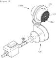
- Fig. 2 is a perspective view of a premixed metal fiber burner 120a of the steam methane reformer 100 of Fig. 1
- Fig. 3 is a perspective view of flashback preventing means 128,
- Fig. 4 is a graph showing an internal temperature of a combustion part 120 when the premixed metal fiber burner 120a is used.
- the steam methane reformer 100 includes a reforming part 110 which produces hydrogen by a reforming reaction, and a combustion part 120 which maintains a high temperature required for the reforming reaction.
- the reforming part 110 is provided with a plurality of reaction tubes 110a in which a catalyst for steam-reforming hydrocarbon materials and producing hydrogen is disposed, respectively.
- the combustion part 120 is provided with the premixed metal fiber burner 120a which generates heat required for the steam reforming reaction, and the premixed metal fiber burner 120a will be fully described below.
- the steam methane reformer 100 of the present invention further includes a raw material supplying part 130 for supplying the hydrocarbon materials to the reaction tube 110a of the reforming part 110, and a hydrogen discharging part 140 for discharging hydrogen produced by the steam reforming reaction.
- the steam methane reformer 100 using a high performing metal fiber burner according to the present invention is an example showing that the premixed metal fiber burner 120a is disposed at an upper center portion of the steam methane reformer 100 so that the combustion part 120 is formed at a center portion thereof in a direction of flame generated by the premixed metal fiber burner 120a and the reforming part 110 is formed to enclose the combustion part 120.
- the plurality of reaction tubes 110a are provided in the structure of Fig. 1 , it is possible to uniformly apply heat to each reaction tube 110a, thereby improving the efficiency thereof.
- the raw material supplying part 130 for supplying hydrocarbon fuel such as nature gas, LPG, LNG, gasoline and kerosene includes a passage through which the hydrocarbon fuel can be flowed.
- the hydrogen discharging part 140 for facilely transporting hydrogen produced by the reforming reaction to a next process also includes a passage through which the hydrogen can be flowed.
- the steam methane reformer 100 of the present invention can form a high temperature environment required for the steam reforming reaction of the catalyst by using the premixed metal fiber burner 120a.
- the premixed metal fiber burner 120a includes a main body 121 formed with a cylindrical premixing chamber 122 in which air, fuel and hydrogen are mixed, a metal fiber mat 124 which is formed at one side of the main body 121 to form the flame, a fuel/air supplying part 125 which is formed at the other side of the main body 121 to supply air or fuel necessary to form the flame, a hydrogen supplying part 126 which is formed at another side of the main body 121 to supply the hydrogen, and ignition part 127 for igniting the metal fiber mat 124.
- the main body 121 is a basic housing for forming the premixed metal fiber burner 120a and is formed with the premixing chamber 122 in which the fuel, the air and the hydrogen are mixed before moving to the combustion part 120.
- the metal fiber mat 124 forms the flame toward the combustion part 120 and is formed of NIT200S and Fe-Cr based alloy.
- the metal fiber mat 124 has a "knitted" shape through which the fuel, the air and the hydrogen in the premixing chamber 122 can be flowed.
- the fuel/air supplying part 125 includes air blowing means, a valve for controlling the air flow rate, a valve for controlling the fuel flow rate and controlling means for controlling valves.
- the fuel/air supplying part 125 for supplying the fuel or air necessary to generate the flame is provided at the other side of the main body 121 that the metal fiber mat 124 is not disposed.
- the hydrogen supplying part 126 is also provided at the other side of the main body 121 so that the combustion occurs facilely and simulate off-gas condition.
- the hydrogen supplying part 126 is connected through a pipe having a small diameter, separately from the fuel/air supplying part 125.
- the premixed metal fiber burner 120a further includes a mixing part 123 in which the fuel and the air or the hydrogen are mixed before being introduced into the premixing chamber 122.
- the hydrogen supplying part 126 has a structure which allows an inert gas content of the hydrogen to be increased, thereby supplying the hydrogen containing a large amount of inert gas like nitrogen gas and thus preventing the flashback of the flame.
- the premixed metal fiber burner 120a of the present invention further includes flashback preventing means 128 which is disposed in the premixing chamber 122 and formed with a plurality of specially designed slits and holes 129 to prevent the flashback of the flame.
- the flashback preventing means 128 is arranged to be orthogonal to the flowing direction of the fuel, the air or the hydrogen (i.e., to form a surface orthogonal to an axial direction of the premixing chamber 122), thereby preventing the flashback of the flame. Furthermore, the fuel, the air and the hydrogen are mixed with each other while passing through the flashback preventing means 128, thereby stably generating the flame, preventing incomplete combustion and thus reducing exhaust emissions.
- the flashback preventing means 128 functions to increase a flowing speed of the mixture of the fuel, the air or the hydrogen, and also transfer the heat of the flame to the peripheral portion thereof, thereby prevent the flame in the metal fiber mat 124 from being flowed to the premixing chamber 122.
- the flashback preventing means 128 may be provided in plural. In this case, it is preferable that the surface area of specially designed slits and holes 129 is gradually reduced, as the flashback preventing means 128 is disposed to be adjacent to the flame position. In Fig. 3 , the flame is generated upward.
- the ignition means 127 functions to ignite the metal fiber mat 124, and it can be also used as an auxiliary spark when the metal fiber mat 124 maintains the flame.
- the premixed metal fiber burner 120a is provided with a plurality of temperature measuring means 160 so as to observe the flame characteristic and previously detect the possibility of the flashback.
- the temperature measuring means 160 may be provided in the metal fiber mat 124 or the premixed chamber 122.
- a thermocouple which is not deformed at the high temperature may be used as the temperature measuring means 160 so as to measure the temperature in a very high temperature environment.
- Fig. 4 is a graph showing a temperature distribution of the premixed metal fiber burner 120a according to the present invention, wherein Fig. 4a is a graph of the temperature distribution in a radial direction at a depth of 300mm of the combustion part 120 and Fig. 4b is a graph of the temperature distribution according to an axial length thereof.
- a nozzle mixing burner having a capacity of 55,000 kcal/hr and the premixed metal fiber burner 120a of Fig. 2 are compared in Fig. 4 .
- the premixed metal fiber burner used in Fig. 4 has a capacity of 51,269 kcal/hr, and the fuel is supplied to the metal fiber mat 124 which has a diameter of 130mm. And the mat is formed of a Fe-Cr based alloy of having the maximum durable surface temperature of 1,150°C.
- a hollow triangle shows a temperature of the nozzle mixing burner in a status of LNG of 70% combustion load and Excess O 2 of 8%
- a hollow circle shows a temperature of the nozzle mixing burner in a status of LPG of 70% combustion load and Excess O 2 of 8%
- a solid triangle shows a temperature of the premixed metal fiber burner 120a in a status of LNG of 70% combustion load and Excess O 2 of 8%
- a solid circle (LPG_NMB) shows a temperature of the premixed metal fiber burner 120a in a status of LPG of 70% combustion load and Excess O 2 of 8%.
- the premixed metal fiber burner 120a of the present invention has the higher flame temperature than the nozzle mixing burner. Particularly, it can be understood that the flame temperature becomes higher at a radially center portion of the metal fiber mat 124 and at a portion adjacent to the metal fiber mat 124 in an axial direction.
- Table 1 shows CO concentrations in the nozzle mixing burner and the premixed metal fiber burner 120a.
- the premixed metal fiber burner 120a has a maximum CO concentration of 32ppm (conditions: LNG of 50% combustion load, Excess O 2 of 10%), and shows a low CO concentration on the whole.
- the nozzle mixing burner has a maximum CO concentration of 6500ppm and shows a very high CO concentration on the whole.
- the premixed metal fiber burner 120a has a better combustion characteristic than the nozzle mixing burner.
- Table 1 CO concentrations of the nozzle mixing burner and the premixed metal fiber burner 120a in each combustion condition Fuel Load Excess O 2 , % 2 4 6 8 10 LNG 50 0 0 0 10 32 70 0 0 1 1 1 100 0 0 1 1 1 LPG 50 1 0 1 0 6 70 0 0 0 0 0 100 0 0 0 0 0 (a) premixed metal fiber burner Fuel Load Excess O 2 , % 2 4 8 8 10 LNG 50 980 91 89 126 250 70 5 0 1 15 40 144 31 7 6 4 9 LPG 50 7500 4000 640 245 260 70 4400 330 101 52 107 100 4000 62 27 32 53 (b) nozzle mixing burner
- Fig. 5 is a schematic view of a hydrogen station 1000 according to the present invention.
- the hydrogen station 100 includes the steam methane reformer 100 as described above, separating/refining means 200 for separating/refining hydrogen gas produced by the steam methane reformer 100, hydrogen injecting means 300 for charging hydrogen having a high purity to a target object and a storing part 400 for storing the produced hydrogen.
- the separating/refining means 200 functions to remove the impurities so that the hydrogen maintains a desired purity level.
- the hydrogen station 1000 since the hydrogen station 1000 employs the premixed metal fiber burner 120a, it is possible to rapidly increase a temperature to a desired level required for the steam reforming reaction, thereby improving hydrogen productivity, and also it is possible to reduce harmful exhaust emissions like CO, thereby increasing produced hydrogen purity and thus reducing load of the separating/refining means 200.
- the hydrogen injecting means 300 functions to charge to the target object the hydrogen produced by the steam methane reformer 100 and the separating/refining means 200, and the target object is, for example, a vehicle using a fuel cell and the like.
- the hydrogen injecting means 300 may be configured so as to supply the hydrogen stored in the storing part 400.
- the steam methane reformer using the high performing metal fiber burner and the hydrogen station using the same employ the premixed metal fiber burner, it is possible to rapidly increase a temperature to a desired level required for the steam reforming reaction, thereby improving hydrogen productivity, and also since the premixed metal fiber burner has a relatively short flame length and stably heats a wide range, thereby reducing a size and also reducing harmful exhaust emissions.
Landscapes
- Chemical & Material Sciences (AREA)
- Engineering & Computer Science (AREA)
- Chemical Kinetics & Catalysis (AREA)
- General Chemical & Material Sciences (AREA)
- Sustainable Energy (AREA)
- Sustainable Development (AREA)
- Manufacturing & Machinery (AREA)
- Electrochemistry (AREA)
- Life Sciences & Earth Sciences (AREA)
- Organic Chemistry (AREA)
- Combustion & Propulsion (AREA)
- General Health & Medical Sciences (AREA)
- Inorganic Chemistry (AREA)
- Health & Medical Sciences (AREA)
- Mechanical Engineering (AREA)
- General Engineering & Computer Science (AREA)
- Hydrogen, Water And Hydrids (AREA)
- Fuel Cell (AREA)
Claims (8)
- Dampfmethanreformer, welcher einen Hochleistungs-Metallfaserbrenner einsetzt, umfassend:ein reformierendes Teil (110), welches mit einer Mehrzahl von Reaktionsrohren (110a) versehen ist, in welchen ein Katalysator für Dampfreformierungs-Kohlenwasserstoffmaterialien und für eine Herstellung von Wasserstoff angeordnet ist;ein Verbrennungsteil (120), welches mit einem Vormischmetallfaserbrenner (120a) versehen ist, um eine Hitze zu erzeugen, welche für die Dampfreformierungsreaktion der Reaktionsrohre (110a) erforderlich ist;ein Rohmaterial zuführendes Teil (130), um Kohlenwasserstoffmaterialien den Reaktionsrohren (110a) zuzuführen; undein Wasserstoff auslassendes Teil (140), um Wasserstoff auszulassen, welcher durch die Dampfreformierungsreaktion durch den Katalysator des Reaktionsrohrs (110a) erzeugt wird,dadurch gekennzeichnet, dass der Vormischmetallfaserbrenner (120a) umfasst:einen Hauptkörper (121), welcher mit einer zylindrischen Vormischkammer (122) ausgebildet ist, in welcher Luft, Brennstoff und Wasserstoff gemischt werden;eine Metallfasermatte (124), welche auf einer Seite des Hauptkörpers (121) ausgebildet ist, um eine Flamme auszubilden;ein Brennstoff/Luft zuführendes Teil (125), welches auf der anderen Seite des Hauptkörpers (121) ausgebildet ist, um die Luft oder den Brennstoff zuzuführen;ein Wasserstoff zuführendes Teil (126), welches auf einer anderen Seite des Hauptkörpers (121) ausgebildet ist, um den Wasserstoff zuzuführen; undein Zündteil (127), um die Metallfasermatte (124) zu zünden.
- Dampfmethanreformer nach Anspruch 1, wobei die Vormischkammer (122) ein Mittel (128) zur Verhinderung eines Zurückschlagens aufweist, welches mit einer Mehrzahl von speziell entworfenen Schlitzen und Löchern (129) ausgebildet ist und orthogonal zu einer Strömungsrichtung des Brennstoffs, der Luft oder des Wasserstoffs angeordnet ist, um so eine Strömungsgeschwindigkeit des Brennstoffs, der Luft oder des Wasserstoffs zu erhöhen und auch Hitze der Flamme zu einem Randabschnitt davon zu übertragen, wobei verhindert wird, dass die Flamme bei der Metallfasermatte (124) zu der Vormischkammer (122) zurückschlägt.
- Dampfmethanreformer nach Anspruch 2, wobei der Vormischmetallfaserbrenner (120a) darüber hinaus ein Mischteil (123) aufweist, bei welchem der Brennstoff und die Luft oder der Wasserstoff gemischt werden, bevor sie in die Vormischkammer (122) eingeführt werden.
- Dampfmethanreformer nach Anspruch 2, wobei das Mittel (128) zur Verhinderung eines Zurückschlagens mehrfach in einer Längsrichtung der Vormischkammer (122) vorhanden ist, und wobei ein Flächeninhalt der speziell entworfenen Schlitze und Löcher (129) graduell verringert wird, wenn das Mittel (128) zur Verhinderung eines Zurückschlagens benachbart zu der Metallfasermatte (124) angeordnet wird.
- Dampfmethanreformer nach Anspruch 2, wobei der Wasserstoff zuführende Teil (126) Wasserstoff zuführt, welcher eine große Menge von Inertgas enthält.
- Dampfmethanreformer nach Anspruch 2, wobei der Vormischmetallfaserbrenner (120a) an einer Seite des Dampfmethanreformers (100) angeordnet ist, und wobei das Verbrennungsteil (120) in einer Richtung einer Flamme ausgebildet ist, welche durch den Vormischmetallfaserbrenner (120a) erzeugt wird, und wobei das reformierende Teil (110) ausgebildet ist, um das Verbrennungsteil (120) einzuschließen.
- Dampfmethanreformer nach Anspruch 1, wobei der Vormischmetallfaserbrenner (120a) eine Mehrzahl von Temperaturmessmitteln (160) aufweist.
- Wasserstoffstation umfassend:einen Dampfmethanreformer (100) nach einem der Ansprüche 1 bis 7;Trennungs-/Verfeinerungs-Mittel (200), um eine Reinheit von Wasserstoff, welcher in einem Gas enthalten ist, welches durch den Wasserstoff auslassenden Teil (140) des Dampfmethanreformers (100) gesammelt wird, zu erhöhen;Wasserstoff einspeisende Mittel (300), um Wasserstoff mit einer hohen Reinheit einem Zielobjekt zuzuteilen; undein Speicherteil (400), um den erzeugten Wasserstoff zu speichern.
Applications Claiming Priority (2)
| Application Number | Priority Date | Filing Date | Title |
|---|---|---|---|
| KR1020080008208A KR101403883B1 (ko) | 2008-01-25 | 2008-01-25 | 고성능 메탈 화이버 버너를 이용한 수증기 개질장치 및상기 수증기 개질장치가 포함된 수소 스테이션 |
| PCT/KR2008/007263 WO2009093807A2 (en) | 2008-01-25 | 2008-12-09 | Steam methane reformer and hydrogen station having it using high performing metal fiber burner |
Publications (3)
| Publication Number | Publication Date |
|---|---|
| EP2232622A2 EP2232622A2 (de) | 2010-09-29 |
| EP2232622A4 EP2232622A4 (de) | 2014-01-15 |
| EP2232622B1 true EP2232622B1 (de) | 2017-06-14 |
Family
ID=40901521
Family Applications (1)
| Application Number | Title | Priority Date | Filing Date |
|---|---|---|---|
| EP08871225.2A Active EP2232622B1 (de) | 2008-01-25 | 2008-12-09 | Dampfmethanreformer mit einem hochleistungs-metallfaserbrenner und wasserstoffstation mit dampfmethanreformer |
Country Status (5)
| Country | Link |
|---|---|
| US (1) | US8388707B2 (de) |
| EP (1) | EP2232622B1 (de) |
| KR (1) | KR101403883B1 (de) |
| CN (1) | CN101926036B (de) |
| WO (1) | WO2009093807A2 (de) |
Families Citing this family (22)
| Publication number | Priority date | Publication date | Assignee | Title |
|---|---|---|---|---|
| KR101624359B1 (ko) * | 2010-02-09 | 2016-05-26 | 에스케이이노베이션 주식회사 | 배기가스 배출이 개선된 수증기 개질 반응을 이용한 수소발생장치 |
| EP2705301B1 (de) * | 2011-05-06 | 2016-02-24 | Bekaert Combustion Technology B.V. | Vormischgasbrenner mit temperaturmessung |
| EP2662133A1 (de) * | 2012-05-09 | 2013-11-13 | Casale Chemicals S.A. | Verfahren zum Umgestalten eines Sekundärreformators |
| DE102012016086A1 (de) * | 2012-08-14 | 2014-02-20 | Thyssenkrupp Uhde Gmbh | Vorrichtung und Verfahren zur Eindüsung von Sauerstoff in eine druckaufgeladene Wirbelschichtvergasung |
| CA2892229A1 (en) | 2013-02-14 | 2014-08-21 | Clearsign Combustion Corporation | Startup method and mechanism for a burner having a perforated flame holder |
| US10458649B2 (en) | 2013-02-14 | 2019-10-29 | Clearsign Combustion Corporation | Horizontally fired burner with a perforated flame holder |
| US10571124B2 (en) | 2013-02-14 | 2020-02-25 | Clearsign Combustion Corporation | Selectable dilution low NOx burner |
| EP3055616B1 (de) | 2013-10-07 | 2020-12-09 | ClearSign Technologies Corporation | Brenner für vorgemischten brennstoff mit perforiertem flammenhalter |
| WO2015061760A1 (en) * | 2013-10-24 | 2015-04-30 | Clearsign Combustion Corporation | System and combustion reaction holder configured to transfer heat from a combustion reaction to a fluid |
| US9828288B2 (en) | 2014-08-13 | 2017-11-28 | Clearsign Combustion Corporation | Perforated burner for a rotary kiln |
| KR101695160B1 (ko) * | 2015-04-28 | 2017-01-12 | 한국가스공사 | 수소 제조 장치 |
| KR102071265B1 (ko) * | 2016-10-19 | 2020-01-30 | 세종공업 주식회사 | 발전용 연료개질기 및 그 운전방법 |
| CN107069065B (zh) * | 2017-03-01 | 2023-04-28 | 四川宏达石油天然气工程有限公司 | 一种天然气重整制氢的转化炉 |
| CN107300171A (zh) * | 2017-07-06 | 2017-10-27 | 北京节能技术监测中心 | 一种基于中心回燃烧头的金属纤维前混燃烧器 |
| KR102626808B1 (ko) * | 2019-10-11 | 2024-01-19 | 한국가스공사 | 연소 장치 |
| KR102316259B1 (ko) * | 2020-12-30 | 2021-10-21 | 고등기술연구원연구조합 | 연료 개질 시스템 및 연료 개질 방법 |
| CN112607705B (zh) * | 2021-01-07 | 2022-09-06 | 太原理工大学 | 一种水蒸气甲烷重整制氢装置及工艺 |
| WO2023141218A2 (en) * | 2022-01-19 | 2023-07-27 | Ohmium International, Inc. | System and method for drying using hydrogen combustion exhaust |
| EP4239247A1 (de) * | 2022-03-03 | 2023-09-06 | BDR Thermea Group B.V. | Gasmischverteiler |
| CN115000473A (zh) * | 2022-06-29 | 2022-09-02 | 成都岷山绿氢能源有限公司 | 一种通用液体燃料重整器系统 |
| CN115849302B (zh) * | 2022-12-06 | 2024-08-09 | 中国船舶集团有限公司第七一一研究所 | 氢气制造装置和方法 |
| KR102639053B1 (ko) | 2023-01-27 | 2024-02-21 | 화이버텍 (주) | 탄화수소 열분해 반응장치 |
Family Cites Families (13)
| Publication number | Priority date | Publication date | Assignee | Title |
|---|---|---|---|---|
| US5326631A (en) * | 1993-06-07 | 1994-07-05 | Alzeta Corporation | Unsintered fiber burner made with metal fibers, ceramic fibers and binding agent |
| US20020090329A1 (en) | 2000-08-11 | 2002-07-11 | Marten Ternan | Apparatus for a fuel processing system |
| US6423279B1 (en) | 2000-10-16 | 2002-07-23 | Harvest Energy Technology, Inc. | Compact endothermic catalytic reaction apparatus |
| US6585785B1 (en) * | 2000-10-27 | 2003-07-01 | Harvest Energy Technology, Inc. | Fuel processor apparatus and control system |
| KR100423544B1 (ko) * | 2001-04-23 | 2004-03-18 | 주식회사 경동도시가스 | 컴팩트형 수증기 개질장치 |
| WO2002099173A1 (en) | 2001-06-01 | 2002-12-12 | N.V. Bekaert S.A. | Burner membrane comprising machined metal fiber bundles |
| KR100445183B1 (ko) | 2001-11-29 | 2004-08-21 | 주식회사 경동도시가스 | 플레이트형 수증기 개질장치 |
| JP4140253B2 (ja) * | 2002-03-15 | 2008-08-27 | 日産自動車株式会社 | 燃料改質システム |
| US7341609B2 (en) * | 2002-10-03 | 2008-03-11 | Genesis Fueltech, Inc. | Reforming and hydrogen purification system |
| KR100611640B1 (ko) | 2004-07-23 | 2006-08-11 | 광주과학기술원 | 플립칩형 질화물계 발광소자 및 그 제조방법 |
| KR20060074947A (ko) * | 2004-12-28 | 2006-07-03 | (주)오선텍 | 연료 전지의 수소 공급을 위하여 다단의 메탈화이버를 이용한 개질기의 작동방법및 그 장치 |
| KR100783004B1 (ko) * | 2005-04-22 | 2007-12-07 | (주)오선텍 | 금속단일체형 촉매체가 내장된 수증기 개질장치 |
| US20100055518A1 (en) * | 2008-08-26 | 2010-03-04 | Idatech, Llc | Hydrogen-producing assemblies, fuel cell systems including the same, methods of producing hydrogen gas, and methods of powering an energy-consuming device |
-
2008
- 2008-01-25 KR KR1020080008208A patent/KR101403883B1/ko active Active
- 2008-12-09 WO PCT/KR2008/007263 patent/WO2009093807A2/en not_active Ceased
- 2008-12-09 US US12/863,043 patent/US8388707B2/en active Active
- 2008-12-09 EP EP08871225.2A patent/EP2232622B1/de active Active
- 2008-12-09 CN CN2008801254050A patent/CN101926036B/zh active Active
Also Published As
| Publication number | Publication date |
|---|---|
| WO2009093807A3 (en) | 2009-09-24 |
| WO2009093807A2 (en) | 2009-07-30 |
| CN101926036B (zh) | 2013-12-18 |
| EP2232622A2 (de) | 2010-09-29 |
| CN101926036A (zh) | 2010-12-22 |
| KR20090081997A (ko) | 2009-07-29 |
| KR101403883B1 (ko) | 2014-06-17 |
| EP2232622A4 (de) | 2014-01-15 |
| US8388707B2 (en) | 2013-03-05 |
| US20110044868A1 (en) | 2011-02-24 |
Similar Documents
| Publication | Publication Date | Title |
|---|---|---|
| EP2232622B1 (de) | Dampfmethanreformer mit einem hochleistungs-metallfaserbrenner und wasserstoffstation mit dampfmethanreformer | |
| CN113661317B (zh) | 燃料重整装置和燃料重整方法 | |
| EP1375420B1 (de) | Verfahren und Vorrichtung zur Zubereitung eines Brennstoff/Luft-Gemisches für eine Brennstoffzelle | |
| US6887436B1 (en) | Fast light-off catalytic reformer | |
| EP2810329B1 (de) | Brennstoffzellenmodul | |
| US11050067B2 (en) | Fuel cell system | |
| EP3022791B1 (de) | Brennstoffzellenmodul | |
| JP2009037814A (ja) | 固体酸化物形燃料電池の高温域の温度低減法及びそのための装置 | |
| KR102093864B1 (ko) | 촉매 버너 장치 | |
| EP4573320B1 (de) | Verfahren zum beheizen eines reformers mit einem ammoniak-brenner zur erzeugung einer stabilen flamme | |
| KR20120067814A (ko) | 연료전지용 개질기 버너 | |
| JP5007045B2 (ja) | 間接内部改質型固体酸化物形燃料電池 | |
| KR20220023494A (ko) | 플라즈마-매트릭스 버너 부분산화 개질기 기반의 태양연료 생산 시스템 | |
| JP7178639B2 (ja) | 燃料電池システム | |
| EP1085261A1 (de) | Verbesserter Nozzle-mix Brenner | |
| KR101152586B1 (ko) | 연료 개질 장치 | |
| US20050198900A1 (en) | Method and apparatus for fuel/air preparation for a hydrocarbon reformer | |
| JP5686646B2 (ja) | バーナ | |
| US20060039854A1 (en) | Catalyst for partial oxidation reforming of fuel and fuel reforming apparatus and method using the catalyst | |
| JP2005268118A (ja) | 改質型燃料電池システム及び改質型燃料電池システムの運転制御方法 | |
| JP2009543305A (ja) | 改質器およびアフターバーナを備えた燃料電池システム | |
| EA013775B1 (ru) | Система топливных элементов с риформером и пламенным нейтрализатором | |
| KR102938597B1 (ko) | 탄화수소 연료를 이용한 수소 생산용 촉매 반응기 | |
| JP5446471B2 (ja) | 燃料電池システムの改質装置 | |
| JP2006001780A (ja) | 水素製造装置およびその起動方法 |
Legal Events
| Date | Code | Title | Description |
|---|---|---|---|
| PUAI | Public reference made under article 153(3) epc to a published international application that has entered the european phase |
Free format text: ORIGINAL CODE: 0009012 |
|
| 17P | Request for examination filed |
Effective date: 20100701 |
|
| AK | Designated contracting states |
Kind code of ref document: A2 Designated state(s): AT BE BG CH CY CZ DE DK EE ES FI FR GB GR HR HU IE IS IT LI LT LU LV MC MT NL NO PL PT RO SE SI SK TR |
|
| AX | Request for extension of the european patent |
Extension state: AL BA MK RS |
|
| RIN1 | Information on inventor provided before grant (corrected) |
Inventor name: KIM, YOUNGDAE Inventor name: YOON, YOUNGSEEK Inventor name: JUNG, HONGSEOK Inventor name: LEE, YONGIL Inventor name: CHOI, KEUNSEOB |
|
| DAX | Request for extension of the european patent (deleted) | ||
| RAP1 | Party data changed (applicant data changed or rights of an application transferred) |
Owner name: SK INNOVATION CO., LTD. |
|
| A4 | Supplementary search report drawn up and despatched |
Effective date: 20131217 |
|
| RIC1 | Information provided on ipc code assigned before grant |
Ipc: H01M 8/04 20060101AFI20131210BHEP Ipc: F23D 14/02 20060101ALI20131210BHEP Ipc: C01B 3/38 20060101ALI20131210BHEP Ipc: H01M 8/06 20060101ALI20131210BHEP |
|
| GRAP | Despatch of communication of intention to grant a patent |
Free format text: ORIGINAL CODE: EPIDOSNIGR1 |
|
| INTG | Intention to grant announced |
Effective date: 20170125 |
|
| GRAS | Grant fee paid |
Free format text: ORIGINAL CODE: EPIDOSNIGR3 |
|
| GRAA | (expected) grant |
Free format text: ORIGINAL CODE: 0009210 |
|
| AK | Designated contracting states |
Kind code of ref document: B1 Designated state(s): AT BE BG CH CY CZ DE DK EE ES FI FR GB GR HR HU IE IS IT LI LT LU LV MC MT NL NO PL PT RO SE SI SK TR |
|
| REG | Reference to a national code |
Ref country code: GB Ref legal event code: FG4D |
|
| REG | Reference to a national code |
Ref country code: CH Ref legal event code: EP Ref country code: AT Ref legal event code: REF Ref document number: 901751 Country of ref document: AT Kind code of ref document: T Effective date: 20170615 |
|
| REG | Reference to a national code |
Ref country code: IE Ref legal event code: FG4D |
|
| REG | Reference to a national code |
Ref country code: DE Ref legal event code: R096 Ref document number: 602008050714 Country of ref document: DE |
|
| REG | Reference to a national code |
Ref country code: NL Ref legal event code: MP Effective date: 20170614 |
|
| REG | Reference to a national code |
Ref country code: LT Ref legal event code: MG4D |
|
| PG25 | Lapsed in a contracting state [announced via postgrant information from national office to epo] |
Ref country code: FI Free format text: LAPSE BECAUSE OF FAILURE TO SUBMIT A TRANSLATION OF THE DESCRIPTION OR TO PAY THE FEE WITHIN THE PRESCRIBED TIME-LIMIT Effective date: 20170614 Ref country code: LT Free format text: LAPSE BECAUSE OF FAILURE TO SUBMIT A TRANSLATION OF THE DESCRIPTION OR TO PAY THE FEE WITHIN THE PRESCRIBED TIME-LIMIT Effective date: 20170614 Ref country code: GR Free format text: LAPSE BECAUSE OF FAILURE TO SUBMIT A TRANSLATION OF THE DESCRIPTION OR TO PAY THE FEE WITHIN THE PRESCRIBED TIME-LIMIT Effective date: 20170915 Ref country code: NO Free format text: LAPSE BECAUSE OF FAILURE TO SUBMIT A TRANSLATION OF THE DESCRIPTION OR TO PAY THE FEE WITHIN THE PRESCRIBED TIME-LIMIT Effective date: 20170914 Ref country code: HR Free format text: LAPSE BECAUSE OF FAILURE TO SUBMIT A TRANSLATION OF THE DESCRIPTION OR TO PAY THE FEE WITHIN THE PRESCRIBED TIME-LIMIT Effective date: 20170614 Ref country code: ES Free format text: LAPSE BECAUSE OF FAILURE TO SUBMIT A TRANSLATION OF THE DESCRIPTION OR TO PAY THE FEE WITHIN THE PRESCRIBED TIME-LIMIT Effective date: 20170614 |
|
| REG | Reference to a national code |
Ref country code: AT Ref legal event code: MK05 Ref document number: 901751 Country of ref document: AT Kind code of ref document: T Effective date: 20170614 |
|
| PG25 | Lapsed in a contracting state [announced via postgrant information from national office to epo] |
Ref country code: BG Free format text: LAPSE BECAUSE OF FAILURE TO SUBMIT A TRANSLATION OF THE DESCRIPTION OR TO PAY THE FEE WITHIN THE PRESCRIBED TIME-LIMIT Effective date: 20170914 Ref country code: SE Free format text: LAPSE BECAUSE OF FAILURE TO SUBMIT A TRANSLATION OF THE DESCRIPTION OR TO PAY THE FEE WITHIN THE PRESCRIBED TIME-LIMIT Effective date: 20170614 Ref country code: NL Free format text: LAPSE BECAUSE OF FAILURE TO SUBMIT A TRANSLATION OF THE DESCRIPTION OR TO PAY THE FEE WITHIN THE PRESCRIBED TIME-LIMIT Effective date: 20170614 Ref country code: LV Free format text: LAPSE BECAUSE OF FAILURE TO SUBMIT A TRANSLATION OF THE DESCRIPTION OR TO PAY THE FEE WITHIN THE PRESCRIBED TIME-LIMIT Effective date: 20170614 |
|
| PG25 | Lapsed in a contracting state [announced via postgrant information from national office to epo] |
Ref country code: RO Free format text: LAPSE BECAUSE OF FAILURE TO SUBMIT A TRANSLATION OF THE DESCRIPTION OR TO PAY THE FEE WITHIN THE PRESCRIBED TIME-LIMIT Effective date: 20170614 Ref country code: CZ Free format text: LAPSE BECAUSE OF FAILURE TO SUBMIT A TRANSLATION OF THE DESCRIPTION OR TO PAY THE FEE WITHIN THE PRESCRIBED TIME-LIMIT Effective date: 20170614 Ref country code: SK Free format text: LAPSE BECAUSE OF FAILURE TO SUBMIT A TRANSLATION OF THE DESCRIPTION OR TO PAY THE FEE WITHIN THE PRESCRIBED TIME-LIMIT Effective date: 20170614 Ref country code: AT Free format text: LAPSE BECAUSE OF FAILURE TO SUBMIT A TRANSLATION OF THE DESCRIPTION OR TO PAY THE FEE WITHIN THE PRESCRIBED TIME-LIMIT Effective date: 20170614 Ref country code: EE Free format text: LAPSE BECAUSE OF FAILURE TO SUBMIT A TRANSLATION OF THE DESCRIPTION OR TO PAY THE FEE WITHIN THE PRESCRIBED TIME-LIMIT Effective date: 20170614 |
|
| PG25 | Lapsed in a contracting state [announced via postgrant information from national office to epo] |
Ref country code: IS Free format text: LAPSE BECAUSE OF FAILURE TO SUBMIT A TRANSLATION OF THE DESCRIPTION OR TO PAY THE FEE WITHIN THE PRESCRIBED TIME-LIMIT Effective date: 20171014 Ref country code: IT Free format text: LAPSE BECAUSE OF FAILURE TO SUBMIT A TRANSLATION OF THE DESCRIPTION OR TO PAY THE FEE WITHIN THE PRESCRIBED TIME-LIMIT Effective date: 20170614 Ref country code: PL Free format text: LAPSE BECAUSE OF FAILURE TO SUBMIT A TRANSLATION OF THE DESCRIPTION OR TO PAY THE FEE WITHIN THE PRESCRIBED TIME-LIMIT Effective date: 20170614 |
|
| REG | Reference to a national code |
Ref country code: DE Ref legal event code: R097 Ref document number: 602008050714 Country of ref document: DE |
|
| PLBE | No opposition filed within time limit |
Free format text: ORIGINAL CODE: 0009261 |
|
| STAA | Information on the status of an ep patent application or granted ep patent |
Free format text: STATUS: NO OPPOSITION FILED WITHIN TIME LIMIT |
|
| PG25 | Lapsed in a contracting state [announced via postgrant information from national office to epo] |
Ref country code: DK Free format text: LAPSE BECAUSE OF FAILURE TO SUBMIT A TRANSLATION OF THE DESCRIPTION OR TO PAY THE FEE WITHIN THE PRESCRIBED TIME-LIMIT Effective date: 20170614 |
|
| 26N | No opposition filed |
Effective date: 20180315 |
|
| REG | Reference to a national code |
Ref country code: CH Ref legal event code: PL |
|
| GBPC | Gb: european patent ceased through non-payment of renewal fee |
Effective date: 20171209 |
|
| PG25 | Lapsed in a contracting state [announced via postgrant information from national office to epo] |
Ref country code: SI Free format text: LAPSE BECAUSE OF FAILURE TO SUBMIT A TRANSLATION OF THE DESCRIPTION OR TO PAY THE FEE WITHIN THE PRESCRIBED TIME-LIMIT Effective date: 20170614 |
|
| REG | Reference to a national code |
Ref country code: IE Ref legal event code: MM4A |
|
| PG25 | Lapsed in a contracting state [announced via postgrant information from national office to epo] |
Ref country code: LU Free format text: LAPSE BECAUSE OF NON-PAYMENT OF DUE FEES Effective date: 20171209 Ref country code: MT Free format text: LAPSE BECAUSE OF NON-PAYMENT OF DUE FEES Effective date: 20171209 |
|
| REG | Reference to a national code |
Ref country code: FR Ref legal event code: ST Effective date: 20180831 |
|
| REG | Reference to a national code |
Ref country code: BE Ref legal event code: MM Effective date: 20171231 |
|
| PG25 | Lapsed in a contracting state [announced via postgrant information from national office to epo] |
Ref country code: FR Free format text: LAPSE BECAUSE OF NON-PAYMENT OF DUE FEES Effective date: 20180102 Ref country code: IE Free format text: LAPSE BECAUSE OF NON-PAYMENT OF DUE FEES Effective date: 20171209 |
|
| PG25 | Lapsed in a contracting state [announced via postgrant information from national office to epo] |
Ref country code: BE Free format text: LAPSE BECAUSE OF NON-PAYMENT OF DUE FEES Effective date: 20171231 Ref country code: CH Free format text: LAPSE BECAUSE OF NON-PAYMENT OF DUE FEES Effective date: 20171231 Ref country code: LI Free format text: LAPSE BECAUSE OF NON-PAYMENT OF DUE FEES Effective date: 20171231 Ref country code: GB Free format text: LAPSE BECAUSE OF NON-PAYMENT OF DUE FEES Effective date: 20171209 |
|
| PG25 | Lapsed in a contracting state [announced via postgrant information from national office to epo] |
Ref country code: MC Free format text: LAPSE BECAUSE OF FAILURE TO SUBMIT A TRANSLATION OF THE DESCRIPTION OR TO PAY THE FEE WITHIN THE PRESCRIBED TIME-LIMIT Effective date: 20170614 Ref country code: HU Free format text: LAPSE BECAUSE OF FAILURE TO SUBMIT A TRANSLATION OF THE DESCRIPTION OR TO PAY THE FEE WITHIN THE PRESCRIBED TIME-LIMIT; INVALID AB INITIO Effective date: 20081209 |
|
| PG25 | Lapsed in a contracting state [announced via postgrant information from national office to epo] |
Ref country code: CY Free format text: LAPSE BECAUSE OF NON-PAYMENT OF DUE FEES Effective date: 20170614 |
|
| PG25 | Lapsed in a contracting state [announced via postgrant information from national office to epo] |
Ref country code: TR Free format text: LAPSE BECAUSE OF FAILURE TO SUBMIT A TRANSLATION OF THE DESCRIPTION OR TO PAY THE FEE WITHIN THE PRESCRIBED TIME-LIMIT Effective date: 20170614 |
|
| PG25 | Lapsed in a contracting state [announced via postgrant information from national office to epo] |
Ref country code: PT Free format text: LAPSE BECAUSE OF FAILURE TO SUBMIT A TRANSLATION OF THE DESCRIPTION OR TO PAY THE FEE WITHIN THE PRESCRIBED TIME-LIMIT Effective date: 20170614 |
|
| P01 | Opt-out of the competence of the unified patent court (upc) registered |
Effective date: 20230622 |
|
| PGFP | Annual fee paid to national office [announced via postgrant information from national office to epo] |
Ref country code: DE Payment date: 20241007 Year of fee payment: 17 |