EP2231440B1 - Auslösevorrichtung für eine hupanlage eines kraftfahrzeugs - Google Patents
Auslösevorrichtung für eine hupanlage eines kraftfahrzeugs Download PDFInfo
- Publication number
- EP2231440B1 EP2231440B1 EP09702320A EP09702320A EP2231440B1 EP 2231440 B1 EP2231440 B1 EP 2231440B1 EP 09702320 A EP09702320 A EP 09702320A EP 09702320 A EP09702320 A EP 09702320A EP 2231440 B1 EP2231440 B1 EP 2231440B1
- Authority
- EP
- European Patent Office
- Prior art keywords
- triggering
- steering wheel
- motor vehicle
- triggering device
- detected
- Prior art date
- Legal status (The legal status is an assumption and is not a legal conclusion. Google has not performed a legal analysis and makes no representation as to the accuracy of the status listed.)
- Not-in-force
Links
Images

Classifications
-
- B—PERFORMING OPERATIONS; TRANSPORTING
- B60—VEHICLES IN GENERAL
- B60Q—ARRANGEMENT OF SIGNALLING OR LIGHTING DEVICES, THE MOUNTING OR SUPPORTING THEREOF OR CIRCUITS THEREFOR, FOR VEHICLES IN GENERAL
- B60Q5/00—Arrangement or adaptation of acoustic signal devices
- B60Q5/001—Switches therefor
- B60Q5/003—Switches therefor mounted on the steering wheel
Definitions
- the invention relates to a triggering device for a Hupstrom a motor vehicle according to the preamble of patent claim 1.
- the WO 00 / 64710A shows a tripping device of a Hupstrom a motor vehicle, which is integrated together with an airbag system in the steering column of the motor vehicle.
- the tripping device outputs a tripping signal when two contact surfaces separated by a slight distance come into contact by applying pressure to a radially inner portion of the steering wheel surface.
- the US-A-5965952 shows an integrated in a steering column steering device Hupstrom a motor vehicle, in whose output of a trigger signal by means of a microcontroller and this associated sensors, eg a temperature sensor, with the temperature and / or aging changing material properties of the components of the steering column and / or the triggering device considered become.
- the FR-A-2863564 shows an integrated into a steering column steering device Hupstrom a motor vehicle, in which a trigger signal is output when a circuit is closed by means of a cover member which is located in the hub region on the surface of the steering wheel via contacts.
- a tripping device for a Hupstrom a motor vehicle which is integrated in or on a steering wheel of the motor vehicle.
- This triggering device which is designed in the form of a switch, outputs a trigger signal when in the triggering device or in Switch is detected that a mechanical pressure is exerted on an enclosed medium. Furthermore, a limit value is predetermined in the tripping device, beyond which the tripping signal is output.
- This triggering device is followed by an evaluation unit, by means of which the duration of the output of the signal of the triggering device is detected. This evaluation ensures that the Hupstrom is only put into operation when the specified in the triggering device for the one parameter limit or threshold for a likewise predetermined minimum duration is exceeded.
- the present invention seeks to provide a triggering device for a Hupstrom a motor vehicle that allows the designers of steering wheels greater freedom, which ensures the reliability of Hupstrom better than previously known triggering devices, in which a compact Design of the steering wheel is possible and which also allows a gap and slot-free fluid-tight design of the steering wheel surface.
- a triggering device in which a honing process is triggered only when there are two parameters associated with a honing process.
- the first trip unit is a touch surface, by means of which the system of a hand on a steering wheel surface detected and upon detection of the system of the hand on the steering wheel surface, the first trigger signal can be output, can be prevented in any case that any mechanical stresses of Steering system, for example, in the presence of potholes, etc., in an impact or the like., May occur, a Hupvorgang is triggered because that trigger signal, which indicates the presence of the hand indicated on the touch surface, not present. Only in the event that the hand is on the touch surface or in the immediate vicinity, the first trigger signal is output, which is necessary to put the Hupstrom in operation.
- the second trip unit is designed as a pressure sensor device which is arranged in the steering wheel of the motor vehicle and by means of which the second trigger signal is output when the steering wheel is pressurized, it is ensured that the mere presence of the hand close to the contact surface is insufficient for the purpose Hupstrom put into operation. Rather, a noticeable pressure must be exerted on the pressure sensor device so that it outputs the second trigger signal.
- a mere passing of the hand or sweeping the steering wheel surface, in which the hand device or in the immediate vicinity of the touch surface, does not lead to the commissioning of the Hupstrom, since in the above-described movement of the hand pressurization of the pressure sensor device does not take place and this the second trigger signal does not output.
- This second trigger signal is output by the pressure sensor device only when a pressure is exerted on the steering wheel surface by means of the hand.
- the tactile surface of the triggering device is arranged directly below the surface cover of the steering wheel.
- the first trigger signal can already be generated when the hand or parts of the hand still at a distance of about 5 mm from the surface of the probe surface are located.
- the Hupstrom is not or not put into operation for this case, since the pressure sensor device is not yet pressurized.
- the pressure sensor device has a plurality of pressure sensors, wherein a static certainty of those components between which the pressure sensors are arranged, in particular achievable, if three pressure sensors are provided.
- FIG. 1 illustrated steering wheel system 1 of a motor vehicle, not shown otherwise, is equipped in the manner explained in more detail below with an embodiment of a tripping device according to the invention for a Hupstrom the motor vehicle.
- a steering wheel 2 of the steering wheel system 1 rests in a conventional manner on a steering column 3 of the steering wheel system. 1
- an airbag 4 is integrated into the steering wheel 2 in the usual way.
- a steering wheel surface 5 is formed by the outside of a surface covering 6 made of leather, for example.
- a surface covering 6 made of leather, for example.
- a sensornossstast Structure trained sensing surface 7 which forms a trip unit in the case of the illustrated embodiment, two trip units having tripping device.
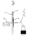
- the operating principle of the touch surface 7 is on FIG. 2 Reference is made, it is apparent that the touch surface 7 has a dielectric plate 8 and an electrode 9. By means of the electrode, a field is pronounced within the dielectric plate 8 and above it, which field is changed or disturbed when approaching a hand 10. In the presence of such a disturbance, as in FIG. 2 indicated, a first trigger signal issued.
- a pressure sensor device 11 is integrated, which may preferably have three pressure sensors 12, of which in FIG. 1 two pressure sensors are shown. If, for example by means of one hand, pressure is exerted on the steering wheel surface 5, this is detected by means of the pressure sensors 12. As a result, a second trigger signal is generated.
- the hoisting gear of the motor vehicle is put into operation. If only the first trigger signal of the touch surface 7 is present or if only the second trigger signal of the pressure sensor device 11 is present, the Hupstrom the motor vehicle is not put into operation.
- the above-described tripping device for the Hupstrom an embodiment of the steering wheel 2 is possible in the case of the steering wheel surface no column or the like. more are needed.
- the steering wheel surface can be made liquid-tight.
Landscapes
- Physics & Mathematics (AREA)
- Acoustics & Sound (AREA)
- Engineering & Computer Science (AREA)
- Mechanical Engineering (AREA)
- Steering Controls (AREA)
- Push-Button Switches (AREA)
- Air Bags (AREA)
- Force Measurement Appropriate To Specific Purposes (AREA)
- Electronic Switches (AREA)
Description
- Die Erfindung bezieht sich auf eine Auslösevorrichtung für eine Hupanlage eines Kraftfahrzeugs nach dem oberbegriff des patentanspruchs 1.
- Bei bekannten Auslösevorrichtungen wird ein Betätigungsglied um einen bestimmten Weg versetzt, so daß dann ein Hupvorgang ausgelöst wird. Im bzw. am Lenkrad muß daher die Möglichkeit zur Verfügung gestellt werden, ein entsprechendes Betätigungsglied um den Auslöseweg verstellen zu können. Hierdurch ergeben sich Beeinträchtigungen hinsichtlich des Designs von Lenkrädern, wobei unter Umständen die Ausgestaltung von Schlitzen, Spalten od.dgl. erforderlich ist, die die Dichtigkeit der Lenkradoberfläche reduzieren.
- Die
WO 00/64710A - Die
US-A-5965952 zeigt eine in eine Lenkradsäule integrierte Auslösevorrichtung einer Hupanlage eines Kraftfahrzeugs, bei deren Ausgabe eines Auslösesignals mittels eines Mikrocontrollers und diesem zugeordneter Sensoren, z.B. eines Temperatursensors, sich mit der Temperatur und/oder der Alterung ändernde Werkstoffeigenschaften der Bauteile der Lenkradsäule und/oder der Auslösevorrichtung berücksichtigt werden. - Die
FR-A-2863564 - Aus der
DE 40 16 047 A1 ist eine Auslösevorrichtung für eine Hupanlage eines Kraftfahrzeugs bekannt, die in bzw. an einem Lenkrad des Kraftfahrzeugs integriert ist. Diese Auslösevorrichtung, die in Form eines Schalters ausgebildet ist, gibt ein Auslösesignal aus, wenn in der Auslösevorrichtung bzw. im Schalter erfasst wird, dass ein mechanischer Druck auf ein eingeschlossenes Medium ausgeübt wird. In der Auslösevorrichtung ist des weiteren ein Grenzwert vorgegeben, ab dessen Überschreiten das Auslösesignal ausgegeben wird. Dieser Auslösevorrichtung nachgeschaltet ist eine Auswerteeinheit, mittels der die Dauer der Ausgabe des Signals der Auslösevorrichtung erfasst wird. Durch diese Auswerteeinheit wird sichergestellt, dass die Hupanlage nur dann in Betrieb gesetzt wird, wenn der in der Auslösevorrichtung für den einen Parameter vorgegebene Grenz- oder Schwellwert für eine ebenfalls vorgebbare Mindestdauer überschritten wird. - Ausgehend von dem vorstehend geschilderten Stand der Technik liegt der Erfindung die Aufgabe zugrunde, eine Auslösevorrichtung für eine Hupanlage eines Kraftfahrzeugs zu schaffen, die den Designern von Lenkrädern größere Freiheiten läßt, die die Betriebssicherheit der Hupanlage besser gewährleistet wie bisher bekannte Auslösevorrichtungen, bei der eine kompakte Gestaltung des Lenkrads möglich ist und die darüber hinaus eine spalt- und schlitzfreie fluiddichte Gestaltung der Lenkradoberfläche zulässt.
- Diese Aufgabe wird erfindungsgemäß durch die Makmale in kennzeichnenden Teil des Harptanspruchs gelöst
- Erfindungsgemäß wird eine Auslösevorrichtung geschaffen, bei der ein Hupvorgang nur ausgelöst wird, wenn zwei mit einem Hupvorgang einhergehende Parameter vorliegen.
- Hierdurch ist es z.B. möglich, die Auslösevorrichtung ohne ein in bezug auf das Lenkrad bzw. auf andere Bauteile des Lenkrads bewegliches Bauteil auszugestalten.
- Wenn bei der Auslösevorrichtung die erste Auslöseeinheit eine Tastfläche ist, mittels der die Anlage einer Hand an einer Lenkradoberfläche erfaß- und bei Erfassen der Anlage der Hand an der Lenkradoberfläche das erste Auslösesignal ausgebbar ist, kann in jedem Fall verhindert werden, daß irgendwelche mechanischen Beanspruchungen der Lenkanlage, die z.B. beim Vorhandensein von Schlaglöchern etc., bei einem Aufprall od.dgl., auftreten können, ein Hupvorgang ausgelöst wird, da dasjenige Auslösesignal, welches das Vorhandensein der Hand an der Tastfläche anzeigt, nicht vorliegt. Nur für den Fall, daß die Hand an der Tastfläche bzw. in deren unmittelbarer Nähe ist, wird das erste Auslösesignal ausgegeben, welches notwendig ist, um die Hupanlage in Betrieb zu setzen.
- Wenn des weiteren die zweite Auslöseeinheit als Drucksensoreinrichtung ausgebildet ist, die im Lenkrad des Kraftfahrzeugs angeordnet ist und mittels der bei einer Druckbeaufschlagung des Lenkrads das zweite Auslösesignal ausgegeben wird, ist sichergestellt, daß allein das Vorhandensein der Hand nahe der Tastfläche nicht ausreichend ist, um die Hupanlage in Betrieb zu setzen. Vielmehr muß auf die Drucksensoreinrichtung ein spürbarer Druck ausgeübt werden, damit diese das zweite Auslösesignal ausgibt. Ein bloßes Vorbeiführen der Hand bzw. Überstreichen der Lenkradoberfläche, bei der die Hand in Anlage oder in unmittelbarer Nähe an die Tastfläche gerät, führt noch nicht zur Inbetriebsetzung der Hupanlage, da bei der vorstehend geschilderten Bewegung der Hand eine Druckbeaufschlagung der Drucksensoreinrichtung nicht erfolgt und diese das zweite Auslösesignal nicht ausgibt. Dieses zweite Auslösesignal wird durch die Drucksensoreinrichtung nur dann ausgegeben, wenn mittels der Hand ein Druck auf die Lenkradoberfläche ausgeübt wird.
- Falls in anderer Weise eine mechanische Beanspruchung bzw. eine Druckbeaufschlagung der Drucksensoreinrichtung erfolgt, führt dies nicht zur Inbetriebsetzung der Hupanlage, da es an der weiteren notwendigen Bedingung, nämlich der Ausgabe des ersten Auslösesignals, mangelt, wenn sich die Hand nicht auf der Lenkradoberfläche, d.h. nahe der Tastfläche, befindet. Die Oberflächenabdeckung des Lenkrads kann gestaltet werden, ohne daß auf die Auslösevorrichtung der Hupanlage in irgendeiner Form Rücksicht genommen werden muß. Vorteilhaft ist die Tastfläche der Auslösevorrichtung unmittelbar unterhalb der Oberflächenabdeckung des Lenkrads angeordnet.
- Wenn die Tastfläche als sensorgesteuerte Funktionstastfläche ausgebildet ist und eine dielektrische Platte sowie eine darunter angeordnete Elektrode aufweist, kann das erste Auslösesignal bereits generiert werden, wenn sich die Hand bzw. Teile der Hand noch in einer Entfernung von ca. 5 mm von der Oberfläche der Tastfläche befinden. Wie bereits mehrfach erwähnt, wird für diesen Fall die Hupanlage nicht bzw. noch nicht in Betrieb gesetzt, da die Drucksensoreinrichtung noch nicht mit Druck beaufschlagt wird.
- Gemäß einer vorteilhaften Weiterbildung weist die Drucksensoreinrichtung mehrere Drucksensoren auf, wobei eine statische Bestimmtheit derjenigen Bauteile, zwischen denen die Drucksensoren angeordnet sind, insbesondere dann erreichbar ist, wenn drei Drucksensoren vorgesehen sind.
- Im folgenden wird die Erfindung anhand einer Ausführungsform unter Bezugnahme auf die Zeichnungen näher dargestellt. Es zeigen:
- Figur 1
- eine Prinzipdarstellung einer Ausführungsform einer in ein Lenkrad integrierten erfindungsgemäßen Auslösevorrichtung für eine Hupanlage eines Kraft- fahrzeugs; und
- Figur 2
- eine Prinzipdarstellung einer Ausführungsform einer Tastfläche der in
Figur 1 gezeigten erfindungsgemäßen Auslösevorrichtung. - Eine in
Figur 1 prinzipiell dargestellte Lenkradanlage 1 eines im übrigen nicht dargestellten Kraftfahrzeugs ist in der im folgenden näher erläuterten Weise mit einer Ausführungsform einer erfindungsgemäßen Auslösevorrichtung für eine Hupanlage des Kraftfahrzeugs ausgerüstet. Ein Lenkrad 2 der Lenkradanlage 1 ruht in üblicher Weise auf einer Lenksäule 3 der Lenkradanlage 1. - Außer der vorstehend bereits erwähnten erfindungsgemäßen Auslösevorrichtung für die Hupanlage ist in das Lenkrad 2 in üblicher Weise ein Airbag 4 integriert.
- Eine Lenkradoberfläche 5 wird durch die Außenseite einer beispielsweise aus Leder ausgeführten Oberflächenabdeckung 6 gebildet. Unterhalb der Oberflächenabdeckung 6 befindet sich eine als Sensor gesteuerte Funktionstastfläche ausgebildete Tastfläche 7, die eine Auslöseeinheit der im Falle des erläuterten Ausführungsbeispiels zwei Auslöseeinheiten aufweisenden Auslösevorrichtung bildet.
- Zum Funktionsprinzip der Tastfläche 7 wird auf
Figur 2 Bezug genommen, aus der hervorgeht, daß die Tastfläche 7 eine dielektrische Platte 8 und eine Elektrode 9 aufweist. Mittels der Elektrode ist innerhalb der dielektrischen Platte 8 und oberhalb derselben ein Feld ausgeprägt, welches bei Annäherung einer Hand 10 verändert bzw. gestört wird. Bei Vorhandensein einer derartigen Störung wird, wie inFigur 2 angedeutet, ein erstes Auslösesignal ausgegeben. - Des weiteren ist im Lenkrad 2 eine Drucksensoreinrichtung 11 integriert, die vorzugsweise drei Drucksensoren 12 aufweisen kann, von denen in
Figur 1 zwei Drucksensoren gezeigt sind. Wird, z.B. mittels einer Hand, auf die Lenkradoberfläche 5 Druck ausgeübt, wird dies mittels der Drucksensoren 12 erfaßt. Hierdurch wird ein zweites Auslösesignal generiert. - Sobald sowohl das erste Auslösesignal der Tastfläche 7 als auch das zweite Auslösesignal der Drucksensoreinrichtung 11 ausgegeben werden, wird mittels der vorstehend geschilderten Auslösevorrichtung die in den Figuren nicht gezeigte Hupanlage des Kraftfahrzeugs in Betrieb gesetzt. Falls nur das erste Auslösesignal der Tastfläche 7 vorliegt oder falls nur das zweite Auslösesignal der Drucksensoreinrichtung 11 vorliegt, wird die Hupanlage des Kraftfahrzeugs nicht in Betrieb gesetzt. Mittels der vorstehend geschilderten Auslösevorrichtung für die Hupanlage ist eine Ausgestaltung des Lenkrads 2 möglich, bei der an der Lenkradoberfläche keinerlei Spalte od.dgl. mehr erforderlich sind. Die Lenkradoberfläche kann flüssigkeitsdicht gestaltet werden.
Claims (6)
- Auslösevorrichtung für eine Hupanlage eines Kraftfahrzeugs, die in bzw. an einem Lenkrad (2) des Kraftfahrzeugs integriert ist, mit zumindest einer ersten Auslöseeinheit (7), mittels der ein mit einem beabsichtigten Hupvorgang einhergehender Parameter erfass- und bei Erfassen eines solchen Parameters ein erstes Auslösesignal ausgebbar ist, dadurch gekennzeichnet, dass die Auslösevorrichtung eine zweite Auslöseeinheit (11) aufweist, mittels der ein weiterer mit einem beabsichtigten Hupvorgang einhergehender Parameter erfassund ein zweites Auslösesignal ausgebbar ist, und dass mittels der Auslösevorrichtung (7, 11) die Hupanlage in Betrieb setzbar ist, wenn sowohl das erste Auslösesignal von der ersten Auslöseeinheit (7) als auch das zweite Auslösesignal von der zweiten Auslöseeinheit (11) ausgegeben werden.
- Auslösevorrichtung nach Anspruch 1, bei der die erste Auslöseeinheit eine Tastfläche (7) ist, mittels der die Anlage einer Hand (10) an einer Lenkradoberfläche (5) erfassund bei Erfassen der Anlage der Hand (10) an der Lenkradoberfläche (5) das erste Auslösesignal ausgebbar ist.
- Auslösevorrichtung nach Anspruch 1 oder 2, bei der die zweite Auslöseeinheit eine Drucksensoreinrichtung (11) ist, die im Lenkrad (2) des Kraftfahrzeugs angeordnet ist und mittels der bei einer Druckbeaufschlagung des Lenkrads (2) das zweite Auslösesignal ausgebbar ist.
- Auslösevorrichtung nach Anspruch 2 oder 3, deren Tastfläche (7) unmittelbar unterhalb einer Oberflächenabdeckung (6) des Lenkrads (2) angeordnet ist.
- Auslösevorrichtung nach einem der Ansprüche 2 bis 4, deren Tastfläche (7) als sensorgesteuerte Funktionstastfläche ausgebildet ist und eine dielektrische Platte (8) und eine darunter angeordnete Elektrode (9) aufweist.
- Auslösevorrichtung nach einem der Ansprüche 3 bis 5, deren Drucksensoreinrichtung (11) mehrere, vorzugsweise drei, Drucksensoren (12) aufweist.
Applications Claiming Priority (2)
| Application Number | Priority Date | Filing Date | Title |
|---|---|---|---|
| DE102008004984A DE102008004984A1 (de) | 2008-01-17 | 2008-01-17 | Auslösevorrichtung für eine Hupanlage eines Kraftfahrzeugs |
| PCT/EP2009/000132 WO2009090031A1 (de) | 2008-01-17 | 2009-01-13 | Auslösevorrichtung für eine hupanlage eines kraftfahrzeugs |
Publications (2)
| Publication Number | Publication Date |
|---|---|
| EP2231440A1 EP2231440A1 (de) | 2010-09-29 |
| EP2231440B1 true EP2231440B1 (de) | 2011-08-31 |
Family
ID=40524649
Family Applications (1)
| Application Number | Title | Priority Date | Filing Date |
|---|---|---|---|
| EP09702320A Not-in-force EP2231440B1 (de) | 2008-01-17 | 2009-01-13 | Auslösevorrichtung für eine hupanlage eines kraftfahrzeugs |
Country Status (7)
| Country | Link |
|---|---|
| US (1) | US8278575B2 (de) |
| EP (1) | EP2231440B1 (de) |
| JP (1) | JP2011509865A (de) |
| CN (1) | CN101909939B (de) |
| AT (1) | ATE522400T1 (de) |
| DE (1) | DE102008004984A1 (de) |
| WO (1) | WO2009090031A1 (de) |
Families Citing this family (8)
| Publication number | Priority date | Publication date | Assignee | Title |
|---|---|---|---|---|
| DE102011111349A1 (de) * | 2010-09-07 | 2012-03-08 | Marquardt Gmbh | Lenkrad für ein Kraftfahrzeug |
| CN102339679A (zh) * | 2011-07-21 | 2012-02-01 | 奥托立夫开发公司 | 安装在车辆方向盘上的喇叭开关 |
| CN103366999B (zh) * | 2012-03-28 | 2015-12-02 | 比亚迪股份有限公司 | 一种汽车喇叭按压力控制装置、方法及汽车 |
| JP6714365B2 (ja) * | 2016-01-15 | 2020-06-24 | 株式会社東海理化電機製作所 | スイッチ装置 |
| CN107264612A (zh) * | 2017-06-29 | 2017-10-20 | 北京新能源汽车股份有限公司 | 方向盘及具有其的车辆控制方法、装置和车辆 |
| US10399489B2 (en) | 2017-08-11 | 2019-09-03 | Otnid Bellot Thompson | Steering wheel horn assembly |
| US10562448B2 (en) | 2017-08-11 | 2020-02-18 | Otnid Bellot Thompson | Steering wheel horn assembly |
| DE102019103752A1 (de) * | 2019-02-14 | 2020-08-20 | Trw Automotive Safety Systems Gmbh | Lenkvorrichtung, Gassackmodul für diese Lenkvorrichtung sowie Verfahren zur Auslösung eines Hupsignals bei einer solchen Lenkvorrichtung |
Family Cites Families (24)
| Publication number | Priority date | Publication date | Assignee | Title |
|---|---|---|---|---|
| JPS56135347A (en) * | 1980-03-25 | 1981-10-22 | Nissan Motor Co Ltd | Switch system on steering wheel |
| JPS62198545A (ja) * | 1986-02-24 | 1987-09-02 | Reiko Saito | 自動車のステアリング装置 |
| DE4016047A1 (de) * | 1990-05-18 | 1991-11-21 | Bayern Chemie Gmbh Flugchemie | Lenkrad mit eingebautem airbag |
| US7057521B1 (en) * | 1991-05-31 | 2006-06-06 | Koninklijke Philips Electronics N.V. | Device with a human-machine interface |
| US5423569A (en) * | 1991-07-08 | 1995-06-13 | United Technologies Automotive, Inc. | Electric signalling in a supplemental passenger restraint system |
| JPH05258639A (ja) * | 1992-03-12 | 1993-10-08 | Nec Corp | スイッチ |
| US5577767A (en) * | 1995-03-08 | 1996-11-26 | Trw Inc. | Housing assembly for an air bag and vehicle horn switch |
| EP0739786B2 (de) * | 1995-04-27 | 2003-05-21 | Toyoda Gosei Co., Ltd. | Lenkrad mit einbegriffener Luftsackeinheit |
| EP0842826A1 (de) * | 1996-11-19 | 1998-05-20 | Autoliv ASP, Inc. | Kraftfahrzeuglenkrad mit Airbag und Hupenschalter |
| US5965952A (en) * | 1998-08-06 | 1999-10-12 | Breed Automotive Technology, Inc. | Vehicle horn and control function switch with compensation and method of operation |
| US6079734A (en) * | 1998-11-23 | 2000-06-27 | Larry J. Winget | Air bag cover assembly having a switch module and method of making same |
| US6135494A (en) * | 1999-04-21 | 2000-10-24 | Breed Automotive Technology Inc. | Occupant proximity sensor with horn switch |
| CN2402542Y (zh) * | 1999-12-15 | 2000-10-25 | 叶小疆 | 机动车控制喇叭 |
| DE20106694U1 (de) * | 2001-04-18 | 2001-08-23 | TRW Automotive Safety Systems GmbH & Co. KG, 63743 Aschaffenburg | Baueinheit aus Gassackmodul und Fahrzeuglenkrad |
| KR100557773B1 (ko) * | 2002-08-21 | 2006-03-07 | 현대모비스 주식회사 | 에어백 모듈의 멤브레인 혼 스위치 구조 |
| FR2863564B1 (fr) | 2003-12-16 | 2007-01-26 | Sc2N Sa | Volant de direction de vehicule automobile |
| JP2006096295A (ja) * | 2004-09-30 | 2006-04-13 | Tokai Rika Co Ltd | ステアリングホイールスイッチ装置 |
| WO2006077997A1 (ja) * | 2005-01-19 | 2006-07-27 | Toyota Jidosha Kabushiki Kaisha | 車両の警報装置 |
| US7060924B1 (en) * | 2005-01-20 | 2006-06-13 | Kyocera Wireless Corp. | Dual tactility keypad switch |
| US7808486B2 (en) * | 2005-02-09 | 2010-10-05 | Research In Motion Limited | Handheld electronic device providing feedback to facilitate navigation and the entry of information, and associated method |
| CN2801552Y (zh) * | 2005-06-17 | 2006-08-02 | 徐昊 | 汽车信号触摸式控制装置 |
| JP2008270023A (ja) * | 2007-04-23 | 2008-11-06 | Tokai Rika Co Ltd | タッチセンサを備えたスイッチ |
| US8003902B1 (en) * | 2008-01-09 | 2011-08-23 | Robert Cannella | Integrated automotive horn/light apparatus and method |
| JP2009298380A (ja) * | 2008-06-17 | 2009-12-24 | Tokai Rika Co Ltd | 入力装置 |
-
2008
- 2008-01-17 DE DE102008004984A patent/DE102008004984A1/de not_active Withdrawn
-
2009
- 2009-01-13 US US12/740,048 patent/US8278575B2/en not_active Expired - Fee Related
- 2009-01-13 CN CN2009801026542A patent/CN101909939B/zh not_active Expired - Fee Related
- 2009-01-13 EP EP09702320A patent/EP2231440B1/de not_active Not-in-force
- 2009-01-13 JP JP2010542570A patent/JP2011509865A/ja active Pending
- 2009-01-13 AT AT09702320T patent/ATE522400T1/de active
- 2009-01-13 WO PCT/EP2009/000132 patent/WO2009090031A1/de not_active Ceased
Also Published As
| Publication number | Publication date |
|---|---|
| ATE522400T1 (de) | 2011-09-15 |
| JP2011509865A (ja) | 2011-03-31 |
| CN101909939B (zh) | 2013-01-30 |
| WO2009090031A1 (de) | 2009-07-23 |
| CN101909939A (zh) | 2010-12-08 |
| DE102008004984A1 (de) | 2009-09-10 |
| US20100276264A1 (en) | 2010-11-04 |
| US8278575B2 (en) | 2012-10-02 |
| EP2231440A1 (de) | 2010-09-29 |
Similar Documents
| Publication | Publication Date | Title |
|---|---|---|
| EP2033313B1 (de) | Einklemmsensor | |
| EP1673866B1 (de) | Sicherheitsschalter, insbesondere not-aus-schalter, zum sicheren abschalten eines gefahrbringenden gerätes | |
| WO2009090031A1 (de) | Auslösevorrichtung für eine hupanlage eines kraftfahrzeugs | |
| DE102010026910B4 (de) | Steuern und Auslesen eines Bedienfelds | |
| DE102020122424A1 (de) | Betätigungsvorrichtung zur Montage an einem Fahrzeugteil, Fahrzeug sowie Betätigungsverfahren zum Auslösen einer Fahrzeugfunktion | |
| DE102011111349A1 (de) | Lenkrad für ein Kraftfahrzeug | |
| WO2012045379A2 (de) | Überwachungs- und notfallsystem für kraftfahrzeuge | |
| DE102008036155B4 (de) | Bedientastenanordnung | |
| EP3369180A1 (de) | Bedienelement, insbesondere in kraftfahrzeugen | |
| DE102005013202B4 (de) | Lenkradschalter | |
| EP3462420A1 (de) | Funkschlüssel für kraftfahrzeuge | |
| DE4016047A1 (de) | Lenkrad mit eingebautem airbag | |
| EP3309967B1 (de) | Kapazitive schalt-vorrichtung | |
| DE102009043601B4 (de) | Hupenanordnung in einem Fahrzeuglenkrad | |
| EP2492786A1 (de) | Bedienelement | |
| DE102018107884B4 (de) | Bedienvorrichtung zum Bedienen von zumindest einem Gerät eines Kraftfahrzeugs, wobei eine Bedienung in Abhängigkeit von zwei physikalischen Parametern durchführbar ist, Kraftfahrzeug sowie Verfahren | |
| DE102015015073A1 (de) | Bedienvorrichtung für ein Kraftfahrzeug und Verfahren zum Betreiben einer Bedienvorrichtung | |
| DE102008023004B4 (de) | Hupenaktivierungseinrichtung sowie Sicherheitseinrichtung mit einer solchen Hupenaktivierungseinrichtung | |
| DE112020001771T5 (de) | Steuervorrichtung für eine akustische warnvorrichtung eines fahrzeugs | |
| EP2629422B1 (de) | Kapazitiver Schalter | |
| EP3410090B1 (de) | Bedienvorrichtung zum bedienen von zumindest einem gerät eines kraftfahrzeugs, wobei durch eine rückstelleinrichtung das bedienelement in eine nullstellung rückführbar ist, kraftfahrzeug sowie verfahren | |
| DE102005046542A1 (de) | Auslöseeinrichtung für Kraftfahrzeuge | |
| DE102019008303A1 (de) | Drucktastensystem | |
| DE102008049008B4 (de) | Elektrischer Taster | |
| DE10229488B3 (de) | Taste zum Auslösen von Steuerungsvorgängen |
Legal Events
| Date | Code | Title | Description |
|---|---|---|---|
| PUAI | Public reference made under article 153(3) epc to a published international application that has entered the european phase |
Free format text: ORIGINAL CODE: 0009012 |
|
| 17P | Request for examination filed |
Effective date: 20100429 |
|
| AK | Designated contracting states |
Kind code of ref document: A1 Designated state(s): AT BE BG CH CY CZ DE DK EE ES FI FR GB GR HR HU IE IS IT LI LT LU LV MC MK MT NL NO PL PT RO SE SI SK TR |
|
| AX | Request for extension of the european patent |
Extension state: AL BA RS |
|
| GRAP | Despatch of communication of intention to grant a patent |
Free format text: ORIGINAL CODE: EPIDOSNIGR1 |
|
| DAX | Request for extension of the european patent (deleted) | ||
| GRAS | Grant fee paid |
Free format text: ORIGINAL CODE: EPIDOSNIGR3 |
|
| GRAA | (expected) grant |
Free format text: ORIGINAL CODE: 0009210 |
|
| RAP1 | Party data changed (applicant data changed or rights of an application transferred) |
Owner name: TAKATA - PETRI AG Owner name: PARAGON AG |
|
| AK | Designated contracting states |
Kind code of ref document: B1 Designated state(s): AT BE BG CH CY CZ DE DK EE ES FI FR GB GR HR HU IE IS IT LI LT LU LV MC MK MT NL NO PL PT RO SE SI SK TR |
|
| REG | Reference to a national code |
Ref country code: GB Ref legal event code: FG4D Free format text: NOT ENGLISH Ref country code: CH Ref legal event code: EP |
|
| REG | Reference to a national code |
Ref country code: IE Ref legal event code: FG4D Free format text: LANGUAGE OF EP DOCUMENT: GERMAN |
|
| REG | Reference to a national code |
Ref country code: DE Ref legal event code: R096 Ref document number: 502009001249 Country of ref document: DE Effective date: 20111103 |
|
| REG | Reference to a national code |
Ref country code: NL Ref legal event code: VDEP Effective date: 20110831 |
|
| LTIE | Lt: invalidation of european patent or patent extension |
Effective date: 20110831 |
|
| PG25 | Lapsed in a contracting state [announced via postgrant information from national office to epo] |
Ref country code: SE Free format text: LAPSE BECAUSE OF FAILURE TO SUBMIT A TRANSLATION OF THE DESCRIPTION OR TO PAY THE FEE WITHIN THE PRESCRIBED TIME-LIMIT Effective date: 20110831 Ref country code: NO Free format text: LAPSE BECAUSE OF FAILURE TO SUBMIT A TRANSLATION OF THE DESCRIPTION OR TO PAY THE FEE WITHIN THE PRESCRIBED TIME-LIMIT Effective date: 20111130 Ref country code: HR Free format text: LAPSE BECAUSE OF FAILURE TO SUBMIT A TRANSLATION OF THE DESCRIPTION OR TO PAY THE FEE WITHIN THE PRESCRIBED TIME-LIMIT Effective date: 20110831 Ref country code: FI Free format text: LAPSE BECAUSE OF FAILURE TO SUBMIT A TRANSLATION OF THE DESCRIPTION OR TO PAY THE FEE WITHIN THE PRESCRIBED TIME-LIMIT Effective date: 20110831 Ref country code: LT Free format text: LAPSE BECAUSE OF FAILURE TO SUBMIT A TRANSLATION OF THE DESCRIPTION OR TO PAY THE FEE WITHIN THE PRESCRIBED TIME-LIMIT Effective date: 20110831 Ref country code: NL Free format text: LAPSE BECAUSE OF FAILURE TO SUBMIT A TRANSLATION OF THE DESCRIPTION OR TO PAY THE FEE WITHIN THE PRESCRIBED TIME-LIMIT Effective date: 20110831 Ref country code: IS Free format text: LAPSE BECAUSE OF FAILURE TO SUBMIT A TRANSLATION OF THE DESCRIPTION OR TO PAY THE FEE WITHIN THE PRESCRIBED TIME-LIMIT Effective date: 20111231 |
|
| PG25 | Lapsed in a contracting state [announced via postgrant information from national office to epo] |
Ref country code: LV Free format text: LAPSE BECAUSE OF FAILURE TO SUBMIT A TRANSLATION OF THE DESCRIPTION OR TO PAY THE FEE WITHIN THE PRESCRIBED TIME-LIMIT Effective date: 20110831 Ref country code: SI Free format text: LAPSE BECAUSE OF FAILURE TO SUBMIT A TRANSLATION OF THE DESCRIPTION OR TO PAY THE FEE WITHIN THE PRESCRIBED TIME-LIMIT Effective date: 20110831 Ref country code: GR Free format text: LAPSE BECAUSE OF FAILURE TO SUBMIT A TRANSLATION OF THE DESCRIPTION OR TO PAY THE FEE WITHIN THE PRESCRIBED TIME-LIMIT Effective date: 20111201 Ref country code: CY Free format text: LAPSE BECAUSE OF FAILURE TO SUBMIT A TRANSLATION OF THE DESCRIPTION OR TO PAY THE FEE WITHIN THE PRESCRIBED TIME-LIMIT Effective date: 20110831 |
|
| REG | Reference to a national code |
Ref country code: IE Ref legal event code: FD4D |
|
| PG25 | Lapsed in a contracting state [announced via postgrant information from national office to epo] |
Ref country code: IE Free format text: LAPSE BECAUSE OF FAILURE TO SUBMIT A TRANSLATION OF THE DESCRIPTION OR TO PAY THE FEE WITHIN THE PRESCRIBED TIME-LIMIT Effective date: 20110831 Ref country code: CZ Free format text: LAPSE BECAUSE OF FAILURE TO SUBMIT A TRANSLATION OF THE DESCRIPTION OR TO PAY THE FEE WITHIN THE PRESCRIBED TIME-LIMIT Effective date: 20110831 Ref country code: SK Free format text: LAPSE BECAUSE OF FAILURE TO SUBMIT A TRANSLATION OF THE DESCRIPTION OR TO PAY THE FEE WITHIN THE PRESCRIBED TIME-LIMIT Effective date: 20110831 |
|
| PG25 | Lapsed in a contracting state [announced via postgrant information from national office to epo] |
Ref country code: PT Free format text: LAPSE BECAUSE OF FAILURE TO SUBMIT A TRANSLATION OF THE DESCRIPTION OR TO PAY THE FEE WITHIN THE PRESCRIBED TIME-LIMIT Effective date: 20120102 Ref country code: IT Free format text: LAPSE BECAUSE OF FAILURE TO SUBMIT A TRANSLATION OF THE DESCRIPTION OR TO PAY THE FEE WITHIN THE PRESCRIBED TIME-LIMIT Effective date: 20110831 Ref country code: PL Free format text: LAPSE BECAUSE OF FAILURE TO SUBMIT A TRANSLATION OF THE DESCRIPTION OR TO PAY THE FEE WITHIN THE PRESCRIBED TIME-LIMIT Effective date: 20110831 Ref country code: EE Free format text: LAPSE BECAUSE OF FAILURE TO SUBMIT A TRANSLATION OF THE DESCRIPTION OR TO PAY THE FEE WITHIN THE PRESCRIBED TIME-LIMIT Effective date: 20110831 Ref country code: RO Free format text: LAPSE BECAUSE OF FAILURE TO SUBMIT A TRANSLATION OF THE DESCRIPTION OR TO PAY THE FEE WITHIN THE PRESCRIBED TIME-LIMIT Effective date: 20110831 |
|
| PG25 | Lapsed in a contracting state [announced via postgrant information from national office to epo] |
Ref country code: DK Free format text: LAPSE BECAUSE OF FAILURE TO SUBMIT A TRANSLATION OF THE DESCRIPTION OR TO PAY THE FEE WITHIN THE PRESCRIBED TIME-LIMIT Effective date: 20110831 |
|
| PLBE | No opposition filed within time limit |
Free format text: ORIGINAL CODE: 0009261 |
|
| STAA | Information on the status of an ep patent application or granted ep patent |
Free format text: STATUS: NO OPPOSITION FILED WITHIN TIME LIMIT |
|
| BERE | Be: lapsed |
Owner name: PARAGON AG Effective date: 20120131 Owner name: TAKATA - PETRI A.G. Effective date: 20120131 |
|
| 26N | No opposition filed |
Effective date: 20120601 |
|
| PG25 | Lapsed in a contracting state [announced via postgrant information from national office to epo] |
Ref country code: MC Free format text: LAPSE BECAUSE OF NON-PAYMENT OF DUE FEES Effective date: 20120131 |
|
| REG | Reference to a national code |
Ref country code: DE Ref legal event code: R082 Ref document number: 502009001249 Country of ref document: DE Representative=s name: SPALTHOFF UND KOLLEGEN, DE |
|
| REG | Reference to a national code |
Ref country code: DE Ref legal event code: R097 Ref document number: 502009001249 Country of ref document: DE Effective date: 20120601 |
|
| REG | Reference to a national code |
Ref country code: DE Ref legal event code: R082 Ref document number: 502009001249 Country of ref document: DE Representative=s name: SPALTHOFF UND KOLLEGEN, DE Effective date: 20120904 Ref country code: DE Ref legal event code: R081 Ref document number: 502009001249 Country of ref document: DE Owner name: PARAGON AG, DE Free format text: FORMER OWNER: PARAGON AG, TAKATA-PETRI AG, , DE Effective date: 20120904 Ref country code: DE Ref legal event code: R081 Ref document number: 502009001249 Country of ref document: DE Owner name: TAKATA AKTIENGESELLSCHAFT, DE Free format text: FORMER OWNER: PARAGON AG, TAKATA-PETRI AG, , DE Effective date: 20120904 Ref country code: DE Ref legal event code: R082 Ref document number: 502009001249 Country of ref document: DE Representative=s name: PATENTANWAELTE SPALTHOFF UND LELGEMANN, DE Effective date: 20120904 Ref country code: DE Ref legal event code: R081 Ref document number: 502009001249 Country of ref document: DE Owner name: PARAGON AG, DE Free format text: FORMER OWNERS: PARAGON AG, 33129 DELBRUECK, DE; TAKATA-PETRI AG, 63743 ASCHAFFENBURG, DE Effective date: 20120904 Ref country code: DE Ref legal event code: R081 Ref document number: 502009001249 Country of ref document: DE Owner name: TAKATA AKTIENGESELLSCHAFT, DE Free format text: FORMER OWNERS: PARAGON AG, 33129 DELBRUECK, DE; TAKATA-PETRI AG, 63743 ASCHAFFENBURG, DE Effective date: 20120904 Ref country code: DE Ref legal event code: R081 Ref document number: 502009001249 Country of ref document: DE Owner name: JOYSON SAFETY SYSTEMS GERMANY GMBH, DE Free format text: FORMER OWNERS: PARAGON AG, 33129 DELBRUECK, DE; TAKATA-PETRI AG, 63743 ASCHAFFENBURG, DE Effective date: 20120904 |
|
| PG25 | Lapsed in a contracting state [announced via postgrant information from national office to epo] |
Ref country code: BE Free format text: LAPSE BECAUSE OF NON-PAYMENT OF DUE FEES Effective date: 20120131 |
|
| PG25 | Lapsed in a contracting state [announced via postgrant information from national office to epo] |
Ref country code: MK Free format text: LAPSE BECAUSE OF FAILURE TO SUBMIT A TRANSLATION OF THE DESCRIPTION OR TO PAY THE FEE WITHIN THE PRESCRIBED TIME-LIMIT Effective date: 20110831 |
|
| PG25 | Lapsed in a contracting state [announced via postgrant information from national office to epo] |
Ref country code: ES Free format text: LAPSE BECAUSE OF FAILURE TO SUBMIT A TRANSLATION OF THE DESCRIPTION OR TO PAY THE FEE WITHIN THE PRESCRIBED TIME-LIMIT Effective date: 20111211 |
|
| PGFP | Annual fee paid to national office [announced via postgrant information from national office to epo] |
Ref country code: FR Payment date: 20130204 Year of fee payment: 5 |
|
| PG25 | Lapsed in a contracting state [announced via postgrant information from national office to epo] |
Ref country code: BG Free format text: LAPSE BECAUSE OF FAILURE TO SUBMIT A TRANSLATION OF THE DESCRIPTION OR TO PAY THE FEE WITHIN THE PRESCRIBED TIME-LIMIT Effective date: 20111130 |
|
| PG25 | Lapsed in a contracting state [announced via postgrant information from national office to epo] |
Ref country code: MT Free format text: LAPSE BECAUSE OF FAILURE TO SUBMIT A TRANSLATION OF THE DESCRIPTION OR TO PAY THE FEE WITHIN THE PRESCRIBED TIME-LIMIT Effective date: 20110831 |
|
| REG | Reference to a national code |
Ref country code: CH Ref legal event code: PL |
|
| GBPC | Gb: european patent ceased through non-payment of renewal fee |
Effective date: 20130113 |
|
| PG25 | Lapsed in a contracting state [announced via postgrant information from national office to epo] |
Ref country code: LI Free format text: LAPSE BECAUSE OF NON-PAYMENT OF DUE FEES Effective date: 20130131 Ref country code: CH Free format text: LAPSE BECAUSE OF NON-PAYMENT OF DUE FEES Effective date: 20130131 |
|
| PG25 | Lapsed in a contracting state [announced via postgrant information from national office to epo] |
Ref country code: GB Free format text: LAPSE BECAUSE OF NON-PAYMENT OF DUE FEES Effective date: 20130113 |
|
| PG25 | Lapsed in a contracting state [announced via postgrant information from national office to epo] |
Ref country code: TR Free format text: LAPSE BECAUSE OF FAILURE TO SUBMIT A TRANSLATION OF THE DESCRIPTION OR TO PAY THE FEE WITHIN THE PRESCRIBED TIME-LIMIT Effective date: 20110831 |
|
| PG25 | Lapsed in a contracting state [announced via postgrant information from national office to epo] |
Ref country code: LU Free format text: LAPSE BECAUSE OF NON-PAYMENT OF DUE FEES Effective date: 20120113 |
|
| PG25 | Lapsed in a contracting state [announced via postgrant information from national office to epo] |
Ref country code: HU Free format text: LAPSE BECAUSE OF FAILURE TO SUBMIT A TRANSLATION OF THE DESCRIPTION OR TO PAY THE FEE WITHIN THE PRESCRIBED TIME-LIMIT Effective date: 20090113 |
|
| REG | Reference to a national code |
Ref country code: FR Ref legal event code: ST Effective date: 20140930 |
|
| PG25 | Lapsed in a contracting state [announced via postgrant information from national office to epo] |
Ref country code: FR Free format text: LAPSE BECAUSE OF NON-PAYMENT OF DUE FEES Effective date: 20140131 |
|
| REG | Reference to a national code |
Ref country code: AT Ref legal event code: MM01 Ref document number: 522400 Country of ref document: AT Kind code of ref document: T Effective date: 20140113 |
|
| PG25 | Lapsed in a contracting state [announced via postgrant information from national office to epo] |
Ref country code: AT Free format text: LAPSE BECAUSE OF NON-PAYMENT OF DUE FEES Effective date: 20140113 |
|
| REG | Reference to a national code |
Ref country code: DE Ref legal event code: R082 Ref document number: 502009001249 Country of ref document: DE Representative=s name: PATENTANWAELTE SPALTHOFF UND LELGEMANN, DE Ref country code: DE Ref legal event code: R081 Ref document number: 502009001249 Country of ref document: DE Owner name: PARAGON AG, DE Free format text: FORMER OWNERS: PARAGON AG, 33129 DELBRUECK, DE; TAKATA AKTIENGESELLSCHAFT, 63743 ASCHAFFENBURG, DE Ref country code: DE Ref legal event code: R081 Ref document number: 502009001249 Country of ref document: DE Owner name: JOYSON SAFETY SYSTEMS GERMANY GMBH, DE Free format text: FORMER OWNERS: PARAGON AG, 33129 DELBRUECK, DE; TAKATA AKTIENGESELLSCHAFT, 63743 ASCHAFFENBURG, DE |
|
| PGFP | Annual fee paid to national office [announced via postgrant information from national office to epo] |
Ref country code: DE Payment date: 20230127 Year of fee payment: 15 |
|
| REG | Reference to a national code |
Ref country code: DE Ref legal event code: R082 Ref document number: 502009001249 Country of ref document: DE Representative=s name: MOSER GOETZE & PARTNER PATENTANWAELTE MBB, DE |
|
| REG | Reference to a national code |
Ref country code: DE Ref legal event code: R119 Ref document number: 502009001249 Country of ref document: DE |
|
| PG25 | Lapsed in a contracting state [announced via postgrant information from national office to epo] |
Ref country code: DE Free format text: LAPSE BECAUSE OF NON-PAYMENT OF DUE FEES Effective date: 20240801 |
|
| PG25 | Lapsed in a contracting state [announced via postgrant information from national office to epo] |
Ref country code: DE Free format text: LAPSE BECAUSE OF NON-PAYMENT OF DUE FEES Effective date: 20240801 |