EP2231046B1 - Plasma-applikatoren für plasmachirurgische verfahren - Google Patents
Plasma-applikatoren für plasmachirurgische verfahren Download PDFInfo
- Publication number
- EP2231046B1 EP2231046B1 EP08864067.7A EP08864067A EP2231046B1 EP 2231046 B1 EP2231046 B1 EP 2231046B1 EP 08864067 A EP08864067 A EP 08864067A EP 2231046 B1 EP2231046 B1 EP 2231046B1
- Authority
- EP
- European Patent Office
- Prior art keywords
- electrode
- plasma
- probe
- resistive element
- plasma applicator
- Prior art date
- Legal status (The legal status is an assumption and is not a legal conclusion. Google has not performed a legal analysis and makes no representation as to the accuracy of the status listed.)
- Active
Links
Images


Classifications
-
- A—HUMAN NECESSITIES
- A61—MEDICAL OR VETERINARY SCIENCE; HYGIENE
- A61B—DIAGNOSIS; SURGERY; IDENTIFICATION
- A61B18/00—Surgical instruments, devices or methods for transferring non-mechanical forms of energy to or from the body
- A61B18/04—Surgical instruments, devices or methods for transferring non-mechanical forms of energy to or from the body by heating
- A61B18/042—Surgical instruments, devices or methods for transferring non-mechanical forms of energy to or from the body by heating using additional gas becoming plasma
Definitions
- the invention relates to plasma applicators for the application of plasma surgery in endoscopy and plasma probes for the application of plasma surgical procedures in flexible endoscopy.
- plasma surgery is meant high frequency surgical procedures in which, as in FIG. 6 shown schematically, high-frequency electrical alternating current (RF current, I HF ) by ionized and consequently electrically conductive gas (plasma), such as argon plasma, specifically applied to or in to be treated biological tissue (target tissue, A, B, C, D) in order to produce medically beneficial thermal effects on or in the target tissue, in particular the devitalization effect (D), coagulation effect (C), desiccation effect (B) and / or shrinkage effect (A), but without collateral tissue (collateral tissue, G) being more than unavoidable and tolerable damage.
- RF current high-frequency electrical alternating current
- plasma ionized and consequently electrically conductive gas
- plasma such as argon plasma
- Plasma surgical procedures and plasma applicators as well as devices for their application are not new.
- a known under the name fulguration or spray coagulation plasma surgical procedure is used in particular for thermal hemostasis in surgical operations.
- the plasma is generated exclusively in air, ie, it mainly produces oxygen plasma and nitrogen plasma.
- Both plasmas are known to be chemically very reactive and produce at the tissue surface Karbonisations bine, pyrolysis effects and consequently vaporization of tissue and smoke.
- the US 4,060,088 has, inter alia, the avoidance of the above-mentioned side effects of fulguration or spray coagulation the subject.
- inert gas helium or argon and mixtures thereof are proposed.
- argon plasma coagulation (APC) is predominantly used today, and this process has been called argon plasma coagulation (APC) for about 20 years to distinguish it from airborne fulguration or spray coagulation.
- a clinically applicable facility for this has been in the US 4,781,175 exclusively for use in open surgery and in rigid endoscopy for thermal haemostasis.
- argon plasma coagulation has not been used only for the coagulation of biological tissues.
- this method is used in particular for the thermal devitalization of pathological tissues and / or for the desiccation and consequently shrinkage of blood vessels and their collateral tissue for the purpose of hemostasis.
- the use of this process for the thermal devitalization of relatively thin fabric layers, such as, for example, is becoming increasingly important mucosa of the gastrointestinal tract or tracheobronchial system.
- This procedure is also becoming increasingly important for the thermal sterilization of tissue surfaces during transmural operations, for example in transgastric operations, in order to prevent germinal exudations from the stomach into the abdominal cavity.
- argon plasma coagulation APC Since the subject of this invention is not limited only to the coagulation of biological tissues and not only to the gas argon, this method will be hereinafter called correspondingly more extensive "plasma surgery”.
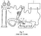
- FIG. 7 An arrangement for the plasma surgery, for endoscopically controlled interventions is in Fig. 7 shown.
- Such an arrangement usually comprises a surgical high-frequency generator 1, which is connected on the one hand to a neutral electrode 2 and on the other hand to a surgical instrument, in this case a probe 10 (or its discharge electrode, not shown).
- the probe 10 is inserted in one of the working channels 6 of an endoscope 5.
- a lumen of the probe 10 is supplied with argon (or another inert gas) from a noble gas source 7.
- the neutral electrode 2 is placed over a large area on a patient and is thus in communication with its biological tissue 3. In this way, the surgeon can treat a target tissue 4 by means of an argon plasma to the desired effects, based on Fig. 6 already described, to achieve there.
- HF generators with high internal resistance are particularly suitable for the treatment of superficial lesions in which a low penetration depth of the thermal effects is expedient.
- HF generators with a low internal resistance are particularly suitable for the treatment of massive lesions in which a large penetration depth of the thermal effects is expedient.
- DE 198 39 826 is described an RF generator whose internal resistance between high and low adjustable.
- the rate of penetration of the thermal effects can be influenced by varying the power or the RF current flowing through the plasma, this becomes due to the high RF voltage required to ionize the gas known RF generators realized by pulse modulation of the RF voltage and the RF current.
- pulse modulation can interfere with video signals from video endoscopes and cause neuromuscular stimuli, especially at modulation frequencies below 1 kHz.
- Another problem with the use of RF generators with low internal resistance for the treatment of superficial lesions are very high temperature of the plasma due to the high RF voltage required for ionization on the one hand and the low internal resistance of the RF generator and the low electrical resistance of the plasma path on the other hand, whereby a very high HF current density and consequently such a high temperature can be caused in the plasma path that the carbonization and pyrolysis effects disturbing this application can arise.
- HF generators with high internal resistance are not appropriate for endoscopic operations or interventions or even not applicable because the high RF voltage required for the ionization of the gas between ionization and target tissue due to the so-called stray capacitance between active RF line and neutral RF line insufficiently or not at all can be transmitted from the RF generator to the ionization electrode. This is known, in particular in flexible endoscopy of the case.
- the EP 1 148 770 A2 and the US 6 958 063 B1 describe a plasma applicator for plasma surgical procedures, which operates insofar on a different principle than the plasma applicator according to the invention, as is not used in the usual way provided neutral electrode.
- the intended there RF generator is to be a resonant transformer, the HF current as "dielectric displacement current from the surface of the patient to ground" flows. This is intended to produce a scab with a surgical cold plasma jet device that proceeds as far as possible without charring or combustion products due to oxygen occlusions.
- the invention is based on the object to show an electrosurgical instrument of the type mentioned so that with little effort and yet with great certainty a sufficiently low penetration depth can be achieved.
- the plasma applicator comprises a rdw - or hose-shaped probe which is provided for insertion into a working channel of a flexible endoscope.
- a plasma applicator for transmitting electrical energy from an electrosurgical RF generator via a lead and an electrode connected at its distal end and further via a current path of ionized gas into a target biological tissue, between the distal end of the lead and the electrode is a resistance element with a predetermined impedance is arranged, which is dimensioned such that after the ionization of the gas, a limitation of a treatment current is ensured.
- An essential point of the invention lies in the fact that the entire arrangement, consisting of RF generator and all leads up to the electrode as “total generator” is considered, the internal resistance is then determined by the resistance element.
- This resistance element can now be selected according to the requirements of the depth of penetration to be achieved or one can provide different instruments for different penetration depths.
- the treatment time still plays a role, but just the critical phase, namely the brief moment after the "ignition" of the arc, during which a high current can flow, defused.
- the resistance element may be an ohmic resistance, which ensures the desired current limit.
- the resistance element is formed as a capacitance or comprises such a capacitance, which has the voltage stability necessary here.
- This capacity forms a high pass, so that low-frequency portions of the current are attenuated. This in turn, it leads to a significant reduction in interference from video systems (as commonly used in endoscopes today) and to avoid neuromuscular irritation, such as those that can occur due to lower frequencies.
- the capacitive resistance can be realized by commercially available components, for example high-voltage resistant ceramic capacitors.
- plasma applicators of the invention guided by narrow instrumentation channels of flexible endoscopes (as in connection with FIG Fig. 7 described), such as plasma applicators or so-called argon plasma coagulation probes (APC probes), for example, according to DE 198 20 240 or DE 101 29 699 respectively.
- APC probes argon plasma coagulation probes
- EP 1 397 082 those having an outer diameter of only 2 to 3.5 mm, these capacitive resistances must be developed specifically for these plasma applicators or constructively realized by appropriate design of the distal end of the APC probes.
- the resistance element comprises a subsection of the connection line arranged in the probe and / or the electrode.
- portions of these components are used either to form a resistive resistor or (optionally additionally) to form a capacitance.
- This can be done, for example, by the resistance element being formed by sections of the connection line and / or a supply line to the electrode and / or the electrode itself, which are electrically insulated from one another, parallel or twisted or coaxially arranged.
- Such a construction is relatively simple. In this case, care should also be taken that no inductances arise, which can be done, for example, by using biphilar line arrangements.
- the resistive element has a capacitance of 10 pF to about 1,000 pF. These are capacitance ranges that result in currents commonly used in high frequency surgery to ensure the desired relatively low penetration depth.
- the dielectric used for the formation of the capacitance should have the highest possible dielectric constant.
- plastics but above all ceramic material, which is introduced as insulation and / or dielectric are suitable. This can be rigid ceramic material or (if greater flexibility is required) also powdered ceramic material.
- a protective gas a noble gas (in particular argon) is used.
- the electrode is located in the probe and is positioned such that a noble gas, in particular argon, can be supplied as a gas to be ionized into a space between the electrode and the target tissue.
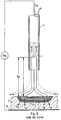
- Fig. 1 is shown very schematically an arrangement that in principle of those Fig. 7 equivalent. This in Fig. 7 shown endoscope is not visible in this arrangement.
- a high-frequency generator which comprises a voltage source with a voltage U 0 and an internal resistance 8 with a resistance value R; having.
- a voltage U 1 U 1 U 0 - R i * I HF 1 at the output terminals of the generator 1 at.
- the generator is connected via a feed line 11 with a probe feed line 12, which is arranged within a tube of the probe 10.
- the probe lead 12 is connected at its distal end via a resistance element 20 and an electrode lead 24 to an electrode 13.
- Argon gas Ar is passed through the tube of the probe 10 so that a space between the distal end of the probe 10 and the biological tissue 3 is filled with argon gas, thus displacing normally air there.
- the gas (argon) in that space between the electrode 13 and the biological tissue 3 is ionized to form an arc 14.
- a current I HF4 flows through the target tissue 4 and the biological tissue 3 to the neutral electrode 2.
- the amount R i of the internal resistance 8 is low.
- the resistor 20 is arranged between the distal end of the (lossy) line 11, 12 and the electrode 13, even with a high ignition voltage available at the electrode 13, a high voltage drop occurs after the arc 14 is ignited generated, so that the current I HF4 can be limited.
- resistance element 20 By no means must be a locally limited resistance element.
- This resistance element 20 can extend in various ways over a certain length to the tip of the electrode 13.
- a distal end of the probe lead 12 is shown having a probe lead wire 21 which is insulated by an insulating material 22.
- the electrode lead 24 is arranged, which is connected to the electrode 13 and provided with an insulation 22 '.
- Fig. 3 The embodiment shown differs from that according to FIG Fig. 2 in that both the distal end of the probe lead wire 21 and the end of the electrode lead 24 are embedded in a common insulation material 22.
- the electrode feed line 24 is formed biphilar, so that any resulting line inductances are compensated.
- insulation material is just in such a case, a ceramic material (designed as solid or powdered ceramic) to achieve the highest possible capacity with a small size of the arrangement.
- the capacitance is increased by winding the electrode lead 24 around the end of the probe lead 12. Again, a biphilic arrangement to avoid inductance can be selected again.
- the electrode feed line 24 is formed as a sleeve which surrounds the distal end of the probe line 12 and thus forms a capacitance with this.
- the electrode is electrically conductively connected via a connection point 25 to the sleeve-shaped electrode feed line 24.
- the sizing can also be similar to the following Fig. 4 take place, so that argon gas supplied no longer flows through the sleeve-shaped electrode lead 24, but outside of this past in the tube 9 of the probe 10.
- the arrangement and the shape of the gas outlet opening can of course not only, as shown in the embodiments, be aligned in the axial direction, they can also be arranged differently, as for example in the DE 198 20 240 A1 or the DE 101 29 699 A1 is shown.
- Limiting the amplitude of the RF current flowing through the plasma not only serves to controllably limit the penetration depth of the thermal effects in the target tissue, but also has several other benefits, such as avoiding too high temperatures of the plasma and thereby avoiding or even carbonization Pyrolysis of the target tissue, the avoidance of thermal overloads of the distal end of the plasma probe, especially when the plasma is directly in contact with plastic, such as in plasma probes accordingly DE 101 29 699 , as well as the possibility to avoid disturbances of video systems and neuromuscular irritation. Neuromuscular irritations are avoided when using plasma probes according to the invention by the capacitive resistance in front of the ionization electrode, in that this capacitive resistance in particular prevents low-frequency currents.
Landscapes
- Health & Medical Sciences (AREA)
- Surgery (AREA)
- Engineering & Computer Science (AREA)
- Life Sciences & Earth Sciences (AREA)
- Biomedical Technology (AREA)
- Otolaryngology (AREA)
- Nuclear Medicine, Radiotherapy & Molecular Imaging (AREA)
- Plasma & Fusion (AREA)
- Physics & Mathematics (AREA)
- Heart & Thoracic Surgery (AREA)
- Medical Informatics (AREA)
- Molecular Biology (AREA)
- Animal Behavior & Ethology (AREA)
- General Health & Medical Sciences (AREA)
- Public Health (AREA)
- Veterinary Medicine (AREA)
- Surgical Instruments (AREA)
Description
- Die Erfindung betrifft Plasma-Applikatoren zur Anwendung der Plasmachirurgie in der Endoskopie sowie Plasma-Sonden zur Anwendung plasmachirurgischer Verfahren in der flexiblen Endoskopie. Mit Plasmachirurgie sind hier hochfrequenzchirurgischen Verfahren gemeint, bei welchen, wie in
Figur 6 schematisch dargestellt, hochfrequenter elektrischer Wechselstrom (HF-Strom, IHF) durch ionisiertes und folglich elektrisch leitfähiges Gas (Plasma), beispielsweise Argon-Plasma, gezielt auf oder in zu behandelndes biologisches Gewebe (Zielgewebe, A, B, C, D) appliziert wird um auf oder im Zielgewebe medizinisch nützliche thermische Effekte, insbesondere den Devitalisationseffekt (D), Koagulationseffekt (C), Desikkationseffekt (B) und/oder Schrumpfungseffekt (A) zu erzeugen, ohne jedoch kollaterales Gewebe (Kollateralgewebe, G) mehr als unvermeidlich und tolerabel zu schädigen. Die Ionisation des Gases zwischen einer Ionisationselektrode (E) und dem Zielgewebe entsteht bei ausreichend hoher elektrischer Feldstärke (Fe) entsprechend der Funktion Fe = UHF : d. Zur Ionisation von Argon bei atmosphärischem Druck sind ca. 500 V/mm erforderlich. Der konstruktive Aufbau verschiedener Plasma-Applikatoren bzw. Plasma-Sonden (R) wird weiter unten ausführlich beschrieben. - Plasmachirurgische Verfahren und Plasma-Applikatoren sowie Einrichtungen zu deren Anwendung sind nicht neu. Bereits seit mehr als 50 Jahren wird ein unter der Bezeichnung Fulguration oder Spray-Koagulation bekanntes plasmachirurgisches Verfahren insbesondere zur thermischen Hämostase bei chirurgischen Operationen angewendet. Hierbei wird das Plasma ausschließlich in Luft erzeugt, d.h. es entstehen vorwiegend Sauerstoffplasma und Stickstoffplasma. Beide Plasmen sind bekanntlich chemisch sehr reaktiv und erzeugen an der Gewebeoberfläche Karbonisationseffekte, Pyrolyseeffekte und folglich auch Vaporisation von Gewebe und Rauch. Diese unbeabsichtigten Nebeneffekte der Fulguration bzw. Spray-Koagulation stören bzw. behindern die Anwendung dieses plasmachirurgischen Verfahrens insbesondere bei endoskopischen Operationen.
- Die
US 4,060,088 hat u.a. die Vermeidung der oben aufgeführten Nebeneffekte der Fulguration bzw. Spray-Koagulation zum Gegenstand. Dort wird vorgeschlagen, die Luft zwischen der Aktivelektrode und dem zu behandelnden Gewebe durch ein chemisch inertes Gas bzw. Edelgas zu ersetzen. Als Edelgas werden Helium oder Argon sowie Gemische hiervon vorgeschlagen. Wegen seines relativ geringen Preises wird heute jedoch vorwiegend Argon angewendet und dieses Verfahren zwecks Abgrenzung zu der in Luft stattfindenden Fulguration bzw. Spray-Koagulation seit ca. 20 Jahren Argon-Plasma-Koagulation (APC) genannt. Eine klinisch anwendbare Einrichtung hierfür wurde in derUS 4,781,175 und zwar ausschließlich zur Anwendung in der offenen Chirurgie und in der starren Endoskopie zur thermischen Blutstillung vorgeschlagen. - Für die APC geeignete Einrichtungen und Verfahren sind erstmals 1994 von G. Farin und K.E. Grund beschrieben worden (G. Farin, K.E. Grund: Technology of Argon Plasma Coagulation with Particular Regard to Endoscopic Applications. Endoscopic Surgery and Allied Technologies, No. 1 Volum 2, 1994: 71-77; sowie K.E. Grund, D. Storek, G. Farin: Endoscopic Argon Plasma Coagulation (APC): First Clinical Experiences in Flexible Endoscopy. Endoscopic Surgery and Allied Technologies, No. 1 Volum 2, 1994: 42-46). Das Anwendungsspektrum der APC in der flexiblen Endoskopie wurde früher beschrieben (K.E. Grund, C. Zindel, G. Farin: Argonplasmakoagulation in der flexiblen Endoskopie: Bewertung eines neuen therapeutischen Verfahrens nach 1606 Anwendungen. Deutsche Medizinische Wochenschrift 122, 1977: 432-438) und gehört heute weltweit zum Standard nicht nur in der flexiblen Endoskopie.
- Wie in oben zitierten Publikationen beschrieben, wurde die Argon-Plasma-Koagulation nicht nur zur Koagulation biologischer Gewebe angewendet. Heute wird dieses Verfahren insbesondere zur thermische Devitalisierung pathologische Gewebe und/oder zur Desikkation und folglich Schrumpfung von Blutgefäßen und deren kollateralem Gewebe zum Zwecke der Hämostase angewendet. Immer wichtiger wird die Anwendung dieses Verfahrens zur thermischen Devitalisierung relativ dünner Gewebeschichten, wie beispielsweise der Mukosa das Gastrointestinaltrakts oder Tracheobronchialsystems. Immer wichtiger wird dieses Verfahren auch zur thermischen Sterilisierung von Gewebeoberflächen bei transmuralen Operationen, beispielweise bei transgastralen Operationen, um Keimdisseminationen aus dem Magen in die Bauchhöhle zu vermeiden. Diese Anwendungen werden von der Bezeichnung Argon-Plasma-Koagulation (APC) nicht adäquat erfasst. Da der Gegenstand dieser Erfindung nicht nur auf die Koagulation biologischer Gewebe und auch nicht nur auf das Gas Argon begrenzt ist, wird dieses Verfahren im Folgenden entsprechend umfassender "Plasmachirurgie" genannt.
- Das breite Anwendungsspektrum der Plasmachirurgie stellt heute allerdings differenziertere anwendungsspezifische Anforderungen an die Eigenschaften der hierfür erforderlichen Einrichtungen, insbesondere bezüglich Reproduzierbarkeit der beabsichtigten thermischen Effekte auf bzw. in Zielgeweben sowie der Vermeidung unbeabsichtigter thermischer Effekte sowohl im Zielgewebe als auch in kollateralen Geweben als dies früher bei Anwendungen der Fulguration bzw. Spray-Koagulation der Fall war. Dies gilt insbesondere bei Anwendung der Plasmachirurgie an bzw. in dünnwandigen Hohlorganen des Gastrointestinaltrakts oder des Tracheobronchialsystems (siehe hierzu G. Farin, K.E. Grund: Principles of Electrosurgery, Laser, and Argon Plasma Coagulation with Particular Regard to Colonoscopy. In: Colonoscopy; Principles and Practice, Edited by J.D. Waye, D.K. Rex and C.B. Williams, Blackwell Publishing 2003: 393-409.
- Das Spektrum verschiedener Plasma-Applikatoren für medizinische Anwendungen, insbesondere für die Plasmachirurgie sowie für endoskopisch kontrollierte Interventionen, ist sehr breit. Bezüglich des Zugangs zu dem jeweils zu behandelnden Zielorgan bzw. Zielgewebe kann man die bisher verfügbaren Plasma-Applikatoren in solche differenzieren, die für die offene Chirurgie, für die starre Endoskopie und für die flexible Endoskopie gestaltet sind. Der prinzipielle Aufbau sowie die Funktion dieser verschiedenen Plasma-Applikatoren ist beispielsweise aus der Publikation von G. Farin und K.E. Grund: Technology of Argon Plasma Coagulation with Particular Regard to Endoscopic Applications, Endoscopic Surgery and Allied Technologies, Thieme Verlag, Stuttgart, No. 1, Volume 2, 1994: 71 - 77, bekannt.
- Eine Anordnung für die Plasmachirurgie, und zwar für endoskopisch kontrollierte Interventionen ist in
Fig. 7 dargestellt. Eine solche Anordnung umfasst üblicherweise einen chirurgischen Hochfrequenzgenerator 1, der einerseits an eine Neutralelektrode 2 und andererseits an ein chirurgisches Instrument, in diesem Fall eine Sonde 10 (bzw. deren nicht gezeigte Entladungselektrode) angeschlossen ist. Die Sonde 10 steckt in einem der Arbeitskanäle 6 eines Endoskops 5. Einem Lumen der Sonde 10 wird Argon (oder ein anderes Edelgas) aus einer Edelgasquelle 7 zugeführt. Die Neutralelektrode 2 wird großflächig an einem Patienten platziert und steht so mit dessen biologischem Gewebe 3 in Verbindung. Auf diese Weise kann der Operateur ein Zielgewebe 4 mittels eines Argon-Plasmas behandeln, um die gewünschten Effekte, die anhand vonFig. 6 bereits beschrieben wurden, dort zu erzielen. - Die für die Plasmachirurgie verfügbaren HF-Generatoren kann man bezüglich ihres Innenwiderstands differenzieren. HF-Generatoren mit hohem Innenwiderstand eignen sich insbesondere für die Behandlung oberflächliche Läsionen, bei welchen eine geringe Penetrationstiefe der thermischen Effekte zweckmäßig ist. HF-Generatoren mit kleinem Innenwiderstand eignen sich insbesondere für die Behandlung massiver Läsionen, bei welchen eine große Penetrationstiefe der thermischen Effekte zweckmäßig ist. In
DE 198 39 826 ist ein HF-Generator beschrieben, dessen Innenwiderstand zwischen hoch und gering einstellbar ist. - Die Behandlung oberflächlicher Läsionen, bei welchen eine geringe Penetrationstiefe der thermischen Effekte zweckmäßig oder gar Voraussetzung sind, ist mit HF-Generatoren mit geringem Innenwiderstand und bekannten Plasma-Applikatoren insofern problematisch, als die Penetrationstiefe der thermischen Effekte vorwiegend durch die Applikationsdauer, also vom Operateur, kontrolliert werden muss. Da die Penetrationsgeschwindigkeit der thermischen Effekte während des Anfangs der Plasma-Applikation relativ schnell ist und über der Zeit degressiv bis zum Erreichen der maximal erreichbaren Penetrationstiefe langsamer wird, ist eine geringe und gleichmäßige Penetrationstiefe der thermischen Effekte bei flächigen Läsionen nur schwierig oder gar nicht realisierbar. Die Penetrationsgeschwindigkeit der thermischen Effekte kann zwar durch Variation der Leistung bzw. des durch das Plasma fließenden HF-Stroms beeinflusst werden, dies wird mit Rücksicht auf die zum Ionisieren des Gases erforderlichen hohen HF-Spannung bei bekannten HF-Generatoren durch Impulsmodulation der HF-Spannung bzw. des HF-Stroms realisiert. Die Pulsmodulation kann jedoch Videosignale von Video-Endoskopen stören und neuromuskuläre Reize verursachen, letzteres insbesondere bei Modulationsfrequenzen unterhalb 1 kHz. Ein weiteres Problem bei der Anwendung von HF-Generatoren mit geringem Innenwiderstand zur Behandlung oberflächlicher Läsionen sind sehr hohe Temperatur des Plasmas infolge der zum Ionisieren erforderlichen hohen HF-Spannung einerseits und des geringen Innenwiderstand des HF-Generators sowie des geringen elektrischen Widerstands der Plasmastrecke andererseits, wodurch in der Plasmastrecke eine sehr hohe HF-Stromdichte und folglich derart hohe Temperatur verursacht werden können, dass die bei diesen Anwendung störenden Karbonisations- und Pyrolyseeffekte entstehen können.
- HF-Generatoren mit hohem Innenwiderstand sind für endoskopisch Operationen bzw. Interventionen nicht zweckmäßig oder gar nicht anwendbar, weil die für die Ionisation des Gases zwischen Ionisationselektrode und Zielgewebe erforderliche hohe HF-Spannung infolge der sogenannten Streukapazität zwischen aktiver HF-Leitung und neutraler HF-Leitung nur ungenügend oder gar nicht vom HF-Generator auf die Ionisationselektrode übertragen werden kann. Dies ist bekanntlich insbesondere bei der flexiblen Endoskopie der Fall.
- HF-Generatoren entsprechend
DE 198 39 826 sind bisher nicht verfügbar. - Die
EP 1 148 770 A2 und dieUS 6 958 063 B1 beschreiben einen Plasma-Applikator für plasmachirurgische Verfahren, der insofern auf einem anderen Prinzip als der erfindungsgemäße Plasmaapplikator arbeitet, als keine in der üblichen Weise vorgesehene Neutralelektrode verwendet wird. Der dort vorgesehene HF-Generator soll ein Resonanzübertrager sein, wobei der HF-Strom als "dielektrischer Verschiebungsstrom von der Oberfläche des Patienten nach Masse" abfließt. Dadurch soll eine Verschorfung mit einem chirurgischen Kaltplasmastrahlgerät erzeugt werden, die soweit wie möglich ohne Verkohlung oder Verbrennungsprodukte aufgrund von Sauerstoffeinschlüssen abläuft. - Zur Lösung dieser Aufgabe wird in der Druckschrift vorgeschlagen, im Handstück des Gerätes einen Kondensator in Reihenschaltung zum Stromkreis vorzusehen. Dieser Kondensator ist in seinem Anbringungsort festgelegt. Auch dann, wenn zum Beispiel eine Leitung zwischen dem Handstück und der Elektrode vorgesehen ist, verbleibt der Kondensator gemäß dem Vorschlag dieser Druckschrift im Handstück.
- Ausgehend vom oben genannten Stand der Technik liegt der Erfindung die Aufgabe zu Grunde, ein elektrochirurgisches Instrument der eingangs genannten Art dahin gehend aufzuzeigen, dass mit geringem Aufwand und dennoch mit großer Sicherheit eine hinreichend geringe Penetrationstiefe erzielbar ist.
- Diese Aufgabe wird durch ein Plasmaapplikator nach Patentanspruch 1 gelöst. Der Plasmaapplikator umfasst eine rdw - oder schlauchförmig ausgebildete Sonde, die zum Einführen in einen Arbeitskanal eines flexiblen Endoskops vorgesehen ist.
- Insbesondere wird die Aufgabe durch ein Plasmaapplikator zum Übertragen elektrischer Energie von einem elektrochirurgischen HF-Generator über eine Anschlussleitung und eine an deren distalem Ende angeschlossene Elektrode und weiter über einen Strompfad aus ionisiertem Gas in ein biologisches Zielgewebe erreicht, wobei zwischen dem distalen Ende der Anschlussleitung und der Elektrode ein Widerstandselement mit vorbestimmter Impedanz angeordnet ist, die derart dimensioniert ist, dass nach der Ionisierung des Gases eine Begrenzung eines Behandlungsstromes sichergestellt ist.
- Ein wesentlicher Punkt der Erfindung liegt also darin, dass die gesamte Anordnung, bestehend aus HF-Generator und allen Zuleitungen bis hin zur Elektrode als "Gesamtgenerator" betrachtet wird, dessen Innenwiderstand dann durch das Widerstandselement bestimmt ist. Dieses Widerstandselement kann nun entsprechend den Anforderungen an die zu erzielende Penetrationstiefe gewählt werden bzw. man kann verschiedene Instrumente für verschiedene Penetrationstiefen zur Verfügung stellen. Selbstverständlich spielt nach wie vor die Behandlungszeit eine Rolle, jedoch ist gerade die kritische Phase, nämlich der kurze Moment nach dem "Zünden" des Lichtbogens, während derer ein hoher Strom fließen kann, entschärft.
- Das Widerstandselement kann ein ohmscher Widerstand sein, der die angestrebte Strombegrenzung sicherstellt. Vorzugsweise wird jedoch das Widerstandselement als Kapazität ausgebildet bzw. umfasst eine solche Kapazität, welche die hier notwendige Spannungsfestigkeit aufweist. Der große Vorteil liegt in diesem Fall darin, dass diese Kapazität einen Hochpass bildet, so dass niederfrequente Anteile des Stromes gedämpft werden. Dies wiederum führt zu einer erheblichen Verminderung von Störungen von Videosystemen (wie sie in Endoskopen heute üblicherweise verwendet werden) und zur Vermeidung von neuromuskulären Reizungen, wie sie durch niedrigere Frequenzen auftreten können.
- Bei ausreichend großen Plasma-Applikatoren kann der kapazitive Widerstand durch handelsübliche Bauelemente, beispielsweise hochspannungsfeste Keramikkondensatoren, realisiert werden. Bei Plasma-Applikatoren der Erfindung, die durch enge Instrumentierkanäle flexibler Endoskope (wie in Zusammenhang mit
Fig. 7 beschrieben) angewendet werden, wie beispielsweise Plasma-Applikatoren bzw. sogenannte Argon-Plasma-Coagulations-Sonden (APC-Sonden), z.B. entsprechendDE 198 20 240 oderDE 101 29 699 bzw.EP 1 397 082 , die einen Außendurchmesser von nur 2 bis 3,5 mm haben, müssen diese kapazitiven Widerstände jedoch speziell für diese Plasma-Applikatoren entwickelt oder konstruktiv durch geeignete Gestaltung des distalen Endes der APC-Sonden realisiert werden. - Da diese bisher sogenannten APC-Sonden selbstverständlich nicht nur mit Argon und auch nicht nur zur Koagulation, sondern auch mit anderen Gasen oder Gasgemischen, für andere thermische Effekte und gegebenen Falls auch in anderen Fachbereichen angewendet werden können, werden diese Plasma-Applikatoren im Folgenden allgemeingültiger Plasma-Sonden (P-Sonden) genannt.
- Bei einer bevorzugten Ausführungsform umfasst das Widerstandselement einen Teilabschnitt der in der sonde angeordneten Anschlusleitung und/oder der Elektrode. Es werden also Abschnitte dieser Bauteile entweder zur Bildung eines ohmscheil Widerstands oder (gegebenenfalls zusätzlich) zur Bildung einer Kapazität verwendet. Dies kann zum Beispiel dadurch geschehen, dass das Widerstandselement durch elektrisch gegeneinander isolierte, parallel geführte oder verdrillte oder koaxial angeordnete Abschnitte der Anschlussleitung und/oder einer Zuleitung zur Elektrode und/oder der Elektrode selbst gebildet wird. Ein solcher Aufbau ist relativ einfach. In diesem Fall sollte auch darauf geachtet werden, dass keine Induktivitäten entstehen, was beispielsweise durch Verwendung biphilarer Leitungsanordnungen geschehen kann.
- Vorzugsweise weist das Widerstandselement eine Kapazität von 10 pF bis etwa 1.000 pF auf. Dies sind Kapazitätsbereiche, die bei den in der Hochfrequenzchirurgie üblicherweise verwendeten Frequenzen zu Strömen führen, welche die gewünschte relativ niedrige Penetrationstiefe sicherstellen.
- Das für die Bildung der Kapazität verwendete Dielektrikum sollte eine möglichst hohe Dielektrizitätskonstante aufweisen. Hierfür eignen sich nicht nur Kunststoffe, sondern vor allem auch Keramikmaterial, das als Isolierung und/oder Dielektrikum eingebracht wird. Dies kann starres Keramikmaterial oder aber (wenn eine höhere Flexibilität gefordert ist) auch pulverförmiges Keramikmaterial sein.
- Alle obigen Punkte gelten auch für solche elektrochirurgischen Anordnungen, in denen kein "Schutzgas" verwendet wird. Vorzugsweise wird jedoch mit einem Schutzgas, einem Edelgas (insbesondere Argon) gearbeitet. Die Elektrode befindet sich der Sonde und ist derart positioniert, dass ein Edelgas, insbesondere Argon, als zu ionisierendes Gas in einen Raum zwischen der Elektrode und dem Zielgewebe zuführbar ist. Die hieraus resultierenden Vorteile wurden oben bereits beschrieben.
- Nachfolgend wird die Erfindung anhand von Abbildungen näher erläutert. Hierbei zeigen
-
Fig. 1 eine schematisierte Darstellung einer Ausführungsform des elektrochirurgischen Instruments, -
Fig. 2-5 schematisierte Darstellungen als kapazitive Elemente ausgebildeten Widerstandselementen und den dazu gehörigen Elektroden, -
Fig. 6 die eingangs angesprochene Darstellung zur Erläuterung der Vorgänge bei der Argon-Plasma-Koagulation und -
Fig. 7 eine Gesamtanordnung zur endoskopischen Behandlung von Geweben mittels APC. - In der nachfolgenden Beschreibung werden für gleiche und gleich wirkende Gegenstände dieselben Bezugsziffern verwendet.
- In
Fig. 1 ist stark schematisiert eine Anordnung gezeigt, die im Prinzip derjenigen ausFig. 7 entspricht. Das inFig. 7 gezeigte Endoskop ist in dieser Anordnung nicht zu sehen. - Wie in
Fig. 1 gezeigt, ist ein Hochfrequenzgenerator vorgesehen, der eine Spannungsquelle mit einer Spannung U0 und einen Innenwiderstand 8 mit einem Widerstandswert R; aufweist. Somit steht bei einem Ausgangsstrom IHF1 am Ausgang des Generators 1 eine Spannung U1
- Die Zuleitung 11 wird üblicherweise als monopolare Leitung ausgebildet. Weiterhin liegt die Neutralelektrode 2 auf Umgebungspotential (ebenso wie ein gegebenenfalls vorgesehenes Endoskop), so dass sich eine relativ große Streukapazität 15 zwischen der Zuleitung 11 sowie eine Streukapazität 16 zwischen der Sondenleitung 12 und der Umgebung bildet. Durch diese Streukapazitäten 15 und 16 fließen Ströme IHF2 bzw. IHF3. Durch diese Streukapazität sinkt schon vor Zünden eines Lichtbogens 14 die Spannung (Uz) ab, die zwischen der Elektrode 13 und dem Zielgewebe 4 zum Zünden Plasmas gebraucht wird:

- Um nun die Zündung des Plasmas 14 bei einem möglichst großen Abstand zwischen der Elektrode 13 und dem Zielgewebe 4 sicherzustellen, ist es von Vorteil, wenn der Betrag Ri des Innenwiderstandes 8 gering ist. Andererseits wird in diesem Fall bei einem Zünden des Lichtbogens 14, der einen sehr geringen Widerstand hat, sowie aufgrund der Tatsache, dass der Widerstand zwischen dem Zielgewebe 4 und der Neutralelektrode 2 ebenfalls relativ gering ist, ein sehr großer Strom IHF4 fließen, so dass in kurzer Zeit das Zielgewebe 4 bis in eine relativ große Tiefe beeinflusst wird. Dadurch nun, dass der Widerstand 20 zwischen dem distalen Ende der (verlustbehafteten) Leitung 11, 12 und der Elektrode 13 angeordnet ist, wird selbst bei einer hohen, an der Elektrode 13 zur Verfügung stehenden Zündspannung, nach dem Zünden des Lichtbogens 14 ein hoher Spannungsabfall erzeugt, so dass der Strom IHF4 begrenzt werden kann. Eine solche Begrenzung des Stromes ist nur durch ein Widerstandselement 20 an dieser Stelle möglich. Es soll hierbei aber unterstrichen werden, dass das Widerstandselement 20 keineswegs ein lokal begrenztes Widerstandselement sein muss. Dieses Widerstandselement 20 kann in verschiedener Weise sich über eine gewisse Länge bis zur Spitze der Elektrode 13 erstrecken.
- Nachfolgend werden verschiedene Ausführungsformen des Widerstandselements anhand der
Fig. 2-5 erläutert. - Bei der in
Fig. 2 gezeigten Ausführungsform ist ein distales Ende der Sondenleitung 12 gezeigt, die einen Sondenleitungsdraht 21 aufweist, der über ein Isoliermaterial 22 isoliert ist. Parallel zu diesem distalen Ende der Sondenleitung 12 ist die Elektrodenzuleitung 24 angeordnet, die mit der Elektrode 13 verbunden und mit einer Isolierung 22' versehen ist. Durch diese Parallelführung der beiden Leitungen 12/24 wird eine Kapazität gebildet, die als Widerstandselement 20 fungiert. - Die in
Fig. 3 gezeigte Ausführungsform unterscheidet sich von der nachFig. 2 dadurch, dass sowohl das distale Ende des Sondenleitungsdrahts 21 als auch das Ende der Elektrodenzuleitung 24 in einem gemeinsamen Isolationsmaterial 22 eingebettet sind. - Darüber hinaus ist die Elektrodenzuleitung 24 biphilar ausgebildet, so dass gegebenenfalls entstehende Leitungsinduktivitäten kompensiert werden. Als Isolationsmaterial eignet sich gerade in einem solchen Fall ein Keramikmaterial (als massive oder als pulverförmige Keramik ausgebildet), um eine möglichst hohe Kapazität bei kleiner Bauform der Anordnung zu erzielen.
- Bei der in
Fig. 4 gezeigten Ausführungsform wird die Kapazität dadurch erhöht, dass die Elektrodenzuleitung 24 um das Ende der Sondenzuleitung 12 gewickelt ist. Auch hier kann wieder eine biphilare Anordnung zur Vermeidung von Induktivitäten gewählt werden. - Bei der in
Fig. 5 gezeigten Anordnung ist die Elektrodenzuleitung 24 als Hülse ausgebildet, welche das distale Ende der Sondenleitung 12 umgibt und so mit dieser eine Kapazität bildet. In diesem Fall ist die Elektrode über eine Verbindungsstelle 25 mit der hülsenförmigen Elektrodenzuleitung 24 elektrisch leitend verbunden. Die Dimensionierung kann auch ähnlich der nachFig. 4 erfolgen, so dass zugeleitetes Argongas nicht mehr durch die hülsenförmige Elektrodenzuleitung 24, sondern außen an dieser vorbei in den Schlauch 9 der Sonde 10 strömt. - Wichtig bei allen Anordnungen ist eine entsprechende Isolation, so dass kein Durchschlag zwischen den durch Leitungen gebildeten Elementen erfolgt. Weiterhin ist es auch möglich, die Leitungen in eine Wand des Schlauches 9 einzubetten, der die Gasleitung der Sonde 10 bildet. Hierbei sei auch angemerkt, dass auch Arbeitskanal 6 des Endoskopes 5 als Gasleitung verwendet werden kann, wie dies beispielsweise in der
EP 0 954 246 A1 beschrieben ist. - Die physikalischen Parameter, welche die Kapazität zwischen den Leitungen bestimmen, sind in der einschlägigen Fachliteratur detailliert beschrieben und sind dem Durchschnittsfachmann bekannt.
- Die Anordnung und die Form der Gasaustrittsöffnung können selbstverständlich nicht nur, wie in den Ausführungsbeispielen gezeigt, in axialer Richtung ausgerichtet sein, sie können auch anders angeordnet sein, wie dies beispielsweise in der
DE 198 20 240 A1 oder derDE 101 29 699 A1 dargestellt ist. - Die Begrenzung der Amplitude des durch das Plasma fließenden HF-Stroms dient nicht nur der kontrollierten Begrenzung der Penetrationstiefe der thermischen Effekte im Zielgewebe, sondern hat außerdem mehrere andere Vorteile, wie beispielsweise die Vermeidung zu hoher Temperaturen des Plasmas und hierdurch die Vermeidung der Karbonisation oder gar Pyrolyse des Zielgewebes, die Vermeidung thermischer Überlastungen des distalen Endes der Plasma-Sonde, insbesondere, wenn das Plasma direkt mit Kunststoff in Berührung kommt, wie beispielsweise bei Plasma-Sonden entsprechend
DE 101 29 699 , und außerdem die Möglichkeit, Störungen von Videosystemen und neuromuskulärer Reizungen zu vermeiden. Neuromuskuläre Reizungen werden bei Anwendung erfindungsgemäßer Plasma-Sonden durch den kapazitiven Widerstand vor der Ionisationselektrode vermieden, indem dieser Kapazitive Widerstand insbesondere niederfrequente Ströme verhindert. -
- 1
- HF-Generator
- 2
- Neutralelektrode
- 3
- biologisches Gewebe
- 4
- Zielgewebe
- 5
- Endoskop
- 6
- Arbeitskanal
- 7
- Edelgasquelle
- 8
- Innenwiderstand
- 9
- Schlauch
- 10
- Sonde
- 11
- Zuleitung
- 12
- Sondenleitung
- 13
- Elektrode
- 14
- Lichtbogen
- 15
- Streukapazität
- 16
- Streukapazität
- 20
- Widerstandselement
- 21
- Sondenleitungsdraht
- 22
- Isolation
- 24
- Elektrodenzuleitung
- 25
- Verbindungsstelle
Claims (10)
- Plasmaapplikator mit:einer Sonde (10);einer Anschlussleitung (11) und einer Sondenleitung (12);einer Elektrode (13);einem Widerstandselement (20) mit vorbestimmter Impedanzwobei die Sonde (10) rohr- oder schlauchförmig ausgebildet ist und zum Einführen in einen Arbeitskanal (6) eines flexiblen Endoskops (5) vorgesehen ist, wobei elektrische Energie von einem elektrochirurgischen HF-Generator (1) über die Anschluss- und Sondenleitung (11, 12) dem Widerstandselement (20) und der Elektrode (13) und weiter über einen Pfad oder Lichtbogen (14) aus ionisiertem Gas in ein biologisches Zielgewebe (4) und über eine neutrale Elektrode (2) zurück zum elektrochirurgischen HF-Generator (1) übertragen wird,dadurch gekennzeichnet, dassdie Sondenleitung (12), das Widerstandselement (20) und die Elektrode (13) innerhalb der Sonde (10) angeordnet sind, wobei die Elektrode (13) am distalen Ende der Sonde (10) angeordnet ist, wobei das Widerstandselement (20) zwischen dem distalen Ende der Sondenleitung(12) und der Elektrode (13) angeordnet und derart dimensioniert ist, dass nach der Ionisierung des Gases durch Erzeugung eines Spannungsabfalls am Widerstandselement (20) eine Begrenzung eines Behandlungsstromes sichergestellt ist.
- Plasmaapplikator nach Anspruch 1,
dadurch gekennzeichnet, dass
das Widerstandselement (20) eine Kapazität umfasst. - Plasmaapplikator nach einem der vorhergehenden Ansprüche,
dadurch gekennzeichnet, dass
das Widerstandselement (20) als Widerstand oder Kondensator ausgebildet ist. - Plasmaapplikator nach einem der vorhergehenden Ansprüche,
dadurch gekennzeichnet, dass
das Widerstandselement (20) einen Teilabschnitt der Sondenleitung (12) und/oder der Elektrode (13) umfasst. - Plasmaapplikator nach Anspruch 4,
dadurch gekennzeichnet, dass
das Widerstandselement (20) durch parallel geführte oder verdrillte oder koaxial angeordnete Teilabschnitte der Sondenleitung (12) und einer Zuleitung (24) zur Elektrode (13) und/oder der Elektrode (13) selbst gebildet ist. - Plasmaapplikator nach Anspruch 5,
dadurch gekennzeichnet, dass
die Teilabschnitte eine niedrige Induktivität aufweisen, wobei sie insbesondere als biphilare Anordnungen ausgebildet sind. - Plasmaapplikator nach einem der vorhergehenden Ansprüche,
dadurch gekennzeichnet, dass
das Widerstandselement eine Kapazität von 10 pF bis 1.000 pF umfasst. - Plasmaapplikator nach einem der vorhergehenden Ansprüche,
dadurch gekennzeichnet, dass
das Widerstandselement (20) ein Keramikmaterial als Isolierung und/oder Dielektrikum umfasst. - Plasmaappliktor nach einem der vorhergehenden Ansprüche,
dadurch gekennzeichnet, dass
die Elektrode (13) innerhalb der Sonde (10) derart angebracht ist, dass ein Edelgas, insbesondere Argon, als zu ionisierendes Gas in einen Raum zwischen der Elektrode (13) und dem Zielgewebe (4) zuführbar ist. - Plasmaapplikator nach Anspruch 8,
dadurch gekennzeichnet, dass
das Keramikmaterial pulverförmig ist.
Applications Claiming Priority (3)
| Application Number | Priority Date | Filing Date | Title |
|---|---|---|---|
| DE102007061482 | 2007-12-20 | ||
| DE200810004843 DE102008004843B4 (de) | 2008-01-17 | 2008-01-17 | Plasma-Applikatoren für plasmachirurgische Verfahren |
| PCT/EP2008/010785 WO2009080273A1 (de) | 2007-12-20 | 2008-12-17 | Plasma-applikatoren für plasmachirurgische verfahren |
Publications (2)
| Publication Number | Publication Date |
|---|---|
| EP2231046A1 EP2231046A1 (de) | 2010-09-29 |
| EP2231046B1 true EP2231046B1 (de) | 2016-03-09 |
Family
ID=40551889
Family Applications (1)
| Application Number | Title | Priority Date | Filing Date |
|---|---|---|---|
| EP08864067.7A Active EP2231046B1 (de) | 2007-12-20 | 2008-12-17 | Plasma-applikatoren für plasmachirurgische verfahren |
Country Status (6)
| Country | Link |
|---|---|
| US (1) | US20110077642A1 (de) |
| EP (1) | EP2231046B1 (de) |
| JP (1) | JP2011506010A (de) |
| CN (1) | CN102006831B (de) |
| ES (1) | ES2565245T3 (de) |
| WO (1) | WO2009080273A1 (de) |
Cited By (1)
| Publication number | Priority date | Publication date | Assignee | Title |
|---|---|---|---|---|
| EP3662854A1 (de) | 2018-12-05 | 2020-06-10 | Erbe Elektromedizin GmbH | Plasmabehandlungseinrichtung |
Families Citing this family (28)
| Publication number | Priority date | Publication date | Assignee | Title |
|---|---|---|---|---|
| US20140188195A1 (en) * | 2012-12-28 | 2014-07-03 | Cold Plasma Medical Technologies, Inc. | Method and Apparatus for Proximity Control in Cold Plasma Medical Devices |
| WO2011015538A1 (de) * | 2009-08-03 | 2011-02-10 | Leibniz-Institut Für Plasmaforschung Und Technologie E. V. | Vorrichtung zur erzeugung eines nichtthermischen atmosphärendruck-plasmas |
| US8083737B2 (en) | 2009-08-26 | 2011-12-27 | Tyco Healthcare Group Lp | Gas-enhanced surgical instrument with mechanism for cylinder puncture |
| JP2013529352A (ja) | 2010-03-31 | 2013-07-18 | コロラド ステート ユニバーシティー リサーチ ファウンデーション | 液体−気体界面プラズマデバイス |
| EP2552340A4 (de) | 2010-03-31 | 2015-10-14 | Univ Colorado State Res Found | Plasmavorrichtung mit flüssig-gas-schnittstelle |
| US8834462B2 (en) | 2010-06-01 | 2014-09-16 | Covidien Lp | System and method for sensing tissue characteristics |
| CN106929401B (zh) * | 2011-05-05 | 2020-06-09 | 安派科生物医学科技有限公司 | 肿瘤细胞检测仪 |
| US9269544B2 (en) | 2013-02-11 | 2016-02-23 | Colorado State University Research Foundation | System and method for treatment of biofilms |
| US9117636B2 (en) | 2013-02-11 | 2015-08-25 | Colorado State University Research Foundation | Plasma catalyst chemical reaction apparatus |
| US9532826B2 (en) | 2013-03-06 | 2017-01-03 | Covidien Lp | System and method for sinus surgery |
| US9555145B2 (en) | 2013-03-13 | 2017-01-31 | Covidien Lp | System and method for biofilm remediation |
| ITTO20130368A1 (it) * | 2013-05-08 | 2014-11-09 | One Technology Electronic S R L | Apparecchio di elettrochirurgia, in particolare per l'ablazione di una massa tissutale dal corpo di un paziente umano od animale. |
| CN103418086B (zh) * | 2013-08-13 | 2015-03-25 | 浙江大学 | 利用高电压产生等离子体的伤口处理装置 |
| CN103767786A (zh) * | 2014-01-11 | 2014-05-07 | 金山 | 甲状腺、颈部外科手术专用电刀刀头 |
| US10237962B2 (en) | 2014-02-26 | 2019-03-19 | Covidien Lp | Variable frequency excitation plasma device for thermal and non-thermal tissue effects |
| US10405913B2 (en) | 2014-10-06 | 2019-09-10 | Us Patent Innovations, Llc | Cold plasma scalpel |
| DE102014116253A1 (de) * | 2014-11-07 | 2016-05-12 | Ovesco Endoscopy Ag | Plasmachirurgisches Gerät mit Abstandshalter |
| US10398490B2 (en) * | 2015-07-07 | 2019-09-03 | Conmed Corporation | Probe with gripping structure for robotic surgical system |
| ITUB20152393A1 (it) * | 2015-07-22 | 2017-01-22 | Otech Ind S R L | Apparecchio di elettrochirurgia per eseguire un’azione di taglio su tessuti di un corpo di un paziente umano od animale. |
| US11246480B2 (en) | 2015-09-07 | 2022-02-15 | Plasmatica Ltd. | Preventing fog on a medical device viewport |
| US11896203B2 (en) | 2015-09-07 | 2024-02-13 | Plasmatica Ltd. | Methods and systems for providing plasma treatments to optical surfaces |
| US11896204B2 (en) | 2015-09-07 | 2024-02-13 | Plasmatica Ltd. | Methods and systems for providing plasma treatments to optical surfaces |
| JP6678744B2 (ja) * | 2015-09-07 | 2020-04-08 | プラズマティカ リミテッド | 医療装置ビューポートの曇り防止 |
| US10524849B2 (en) | 2016-08-02 | 2020-01-07 | Covidien Lp | System and method for catheter-based plasma coagulation |
| GB2570297B (en) * | 2018-01-17 | 2022-10-12 | Gyrus Medical Ltd | Bipolar electrosurgical instruments |
| CN111781856B (zh) * | 2020-06-03 | 2024-05-24 | Oppo广东移动通信有限公司 | 眼镜及其控制方法、存储介质 |
| AU2022260712A1 (en) | 2021-04-22 | 2023-11-30 | Plasmatica Ltd. | Methods and systems for providing plasma treatments to optical surfaces |
| CN118341208B (zh) * | 2024-06-14 | 2024-09-10 | 杭州康基医疗器械有限公司 | 一种负离子自动除烟系统 |
Family Cites Families (10)
| Publication number | Priority date | Publication date | Assignee | Title |
|---|---|---|---|---|
| US4060088A (en) * | 1976-01-16 | 1977-11-29 | Valleylab, Inc. | Electrosurgical method and apparatus for establishing an electrical discharge in an inert gas flow |
| US4781175A (en) * | 1986-04-08 | 1988-11-01 | C. R. Bard, Inc. | Electrosurgical conductive gas stream technique of achieving improved eschar for coagulation |
| US5509916A (en) * | 1994-08-12 | 1996-04-23 | Valleylab Inc. | Laser-assisted electrosurgery system |
| EP0765638A1 (de) * | 1995-09-26 | 1997-04-02 | Erbe Elektromedizin GmbH | Einrichtung zur Koagulation biologischer Gewebe mittels eines ionizierbaren Gases |
| US6958063B1 (en) * | 1999-04-22 | 2005-10-25 | Soring Gmbh Medizintechnik | Plasma generator for radio frequency surgery |
| JP2001178740A (ja) * | 1999-12-24 | 2001-07-03 | Olympus Optical Co Ltd | 内視鏡治療装置 |
| US6676692B2 (en) * | 2001-04-27 | 2004-01-13 | Intek Technology L.L.C. | Apparatus for delivering, repositioning and/or retrieving self-expanding stents |
| US6780178B2 (en) * | 2002-05-03 | 2004-08-24 | The Board Of Trustees Of The Leland Stanford Junior University | Method and apparatus for plasma-mediated thermo-electrical ablation |
| US7316682B2 (en) * | 2002-12-17 | 2008-01-08 | Aaron Medical Industries, Inc. | Electrosurgical device to generate a plasma stream |
| US7957815B2 (en) * | 2005-10-11 | 2011-06-07 | Thermage, Inc. | Electrode assembly and handpiece with adjustable system impedance, and methods of operating an energy-based medical system to treat tissue |
-
2008
- 2008-12-17 WO PCT/EP2008/010785 patent/WO2009080273A1/de not_active Ceased
- 2008-12-17 CN CN200880121854.8A patent/CN102006831B/zh active Active
- 2008-12-17 ES ES08864067.7T patent/ES2565245T3/es active Active
- 2008-12-17 EP EP08864067.7A patent/EP2231046B1/de active Active
- 2008-12-17 US US12/809,490 patent/US20110077642A1/en not_active Abandoned
- 2008-12-17 JP JP2010538454A patent/JP2011506010A/ja active Pending
Cited By (2)
| Publication number | Priority date | Publication date | Assignee | Title |
|---|---|---|---|---|
| EP3662854A1 (de) | 2018-12-05 | 2020-06-10 | Erbe Elektromedizin GmbH | Plasmabehandlungseinrichtung |
| US11684406B2 (en) | 2018-12-05 | 2023-06-27 | Erbe Elektromedizin Gmbh | Plasma treatment device |
Also Published As
| Publication number | Publication date |
|---|---|
| WO2009080273A4 (de) | 2009-09-24 |
| WO2009080273A1 (de) | 2009-07-02 |
| EP2231046A1 (de) | 2010-09-29 |
| ES2565245T3 (es) | 2016-04-01 |
| CN102006831B (zh) | 2014-06-11 |
| US20110077642A1 (en) | 2011-03-31 |
| JP2011506010A (ja) | 2011-03-03 |
| CN102006831A (zh) | 2011-04-06 |
Similar Documents
| Publication | Publication Date | Title |
|---|---|---|
| EP2231046B1 (de) | Plasma-applikatoren für plasmachirurgische verfahren | |
| DE102009048312B4 (de) | Elektrochirurgisches Instrument und Verfahren zur Herstellung eines elektrochirurgischen Instruments | |
| DE69616327T2 (de) | Anordung zum Schneiden und zur elektrochirurgischen Ablation | |
| DE60121544T2 (de) | Ein elektrochirurgisches instrument und ein elektrochirurgisches system mit einem solchen instrument | |
| EP0954246B1 (de) | Koagulationsvorrichtung zur koagulation biologischer gewebe | |
| EP2475318B1 (de) | Multifunktionselement zur verhinderung der karbonisierung von gewebe mittels eines multifunktionselements | |
| EP1567079B1 (de) | Bipolares medizinisches instrument sowie elektrochirurgisches system mit einem solchen instrument | |
| DE69222558T2 (de) | Chirurgische, elektrisch abgeschirmte, röntgendurchlässige Kanüle zum Schutz von Patienten gegen R.F. | |
| DE102008004843B4 (de) | Plasma-Applikatoren für plasmachirurgische Verfahren | |
| EP1296606A1 (de) | Elektrodenanordnung für ein chirurgisches instrument | |
| DE102007003836A1 (de) | Bipolares Instrument und Verfahren zur elektrochirurgischen Behandlung von Gewebe | |
| EP3141203B1 (de) | Ablationseinrichtung zur grossflächigen mukosaablation | |
| DE102005021304A1 (de) | Endoskopische Chirurgieeinrichtung für eine Argon-Plasma-Koagulation (APC) | |
| EP0866672A2 (de) | Anordnung zur elektro-thermischen behandlung des menschlichen oder tierischen körpers | |
| WO2012003966A1 (de) | Elektrodenanordnung | |
| EP3141204B1 (de) | Ablationssystem zur grossflächigen oberflächenkoagulation biologischer gewebe | |
| DE202008004064U1 (de) | Ablationsgerät mit reduzierter Nervenstimulation | |
| EP1139896A1 (de) | Vorrichtung zur schonenden gewebeentnahme aus tierischem oder menschlichem gewebe | |
| DE102009053438B4 (de) | Resektoskop | |
| WO1998042266A1 (de) | Einrichtung zur plasma-koagulation biologischer gewebe | |
| EP3936069B1 (de) | Hochfrequenzelektrode zur verwendung in einem chirurgischen handgerät, elektrodeninstrument und resektoskop | |
| WO2015118083A1 (de) | Plasma-applikator für plasmachirurgische verfahren | |
| DE9219192U1 (de) | Instrument für die Hochfrequenzchirurgie |
Legal Events
| Date | Code | Title | Description |
|---|---|---|---|
| PUAI | Public reference made under article 153(3) epc to a published international application that has entered the european phase |
Free format text: ORIGINAL CODE: 0009012 |
|
| 17P | Request for examination filed |
Effective date: 20100716 |
|
| AK | Designated contracting states |
Kind code of ref document: A1 Designated state(s): AT BE BG CH CY CZ DE DK EE ES FI FR GB GR HR HU IE IS IT LI LT LU LV MC MT NL NO PL PT RO SE SI SK TR |
|
| AX | Request for extension of the european patent |
Extension state: AL BA MK RS |
|
| DAX | Request for extension of the european patent (deleted) | ||
| 17Q | First examination report despatched |
Effective date: 20121122 |
|
| GRAP | Despatch of communication of intention to grant a patent |
Free format text: ORIGINAL CODE: EPIDOSNIGR1 |
|
| INTG | Intention to grant announced |
Effective date: 20150820 |
|
| GRAS | Grant fee paid |
Free format text: ORIGINAL CODE: EPIDOSNIGR3 |
|
| GRAA | (expected) grant |
Free format text: ORIGINAL CODE: 0009210 |
|
| AK | Designated contracting states |
Kind code of ref document: B1 Designated state(s): AT BE BG CH CY CZ DE DK EE ES FI FR GB GR HR HU IE IS IT LI LT LU LV MC MT NL NO PL PT RO SE SI SK TR |
|
| REG | Reference to a national code |
Ref country code: GB Ref legal event code: FG4D Free format text: NOT ENGLISH |
|
| REG | Reference to a national code |
Ref country code: AT Ref legal event code: REF Ref document number: 778897 Country of ref document: AT Kind code of ref document: T Effective date: 20160315 Ref country code: CH Ref legal event code: EP |
|
| REG | Reference to a national code |
Ref country code: ES Ref legal event code: FG2A Ref document number: 2565245 Country of ref document: ES Kind code of ref document: T3 Effective date: 20160401 |
|
| REG | Reference to a national code |
Ref country code: IE Ref legal event code: FG4D Free format text: LANGUAGE OF EP DOCUMENT: GERMAN |
|
| REG | Reference to a national code |
Ref country code: DE Ref legal event code: R096 Ref document number: 502008013909 Country of ref document: DE |
|
| REG | Reference to a national code |
Ref country code: LT Ref legal event code: MG4D |
|
| REG | Reference to a national code |
Ref country code: NL Ref legal event code: MP Effective date: 20160309 |
|
| PG25 | Lapsed in a contracting state [announced via postgrant information from national office to epo] |
Ref country code: HR Free format text: LAPSE BECAUSE OF FAILURE TO SUBMIT A TRANSLATION OF THE DESCRIPTION OR TO PAY THE FEE WITHIN THE PRESCRIBED TIME-LIMIT Effective date: 20160309 Ref country code: GR Free format text: LAPSE BECAUSE OF FAILURE TO SUBMIT A TRANSLATION OF THE DESCRIPTION OR TO PAY THE FEE WITHIN THE PRESCRIBED TIME-LIMIT Effective date: 20160610 Ref country code: NO Free format text: LAPSE BECAUSE OF FAILURE TO SUBMIT A TRANSLATION OF THE DESCRIPTION OR TO PAY THE FEE WITHIN THE PRESCRIBED TIME-LIMIT Effective date: 20160609 Ref country code: FI Free format text: LAPSE BECAUSE OF FAILURE TO SUBMIT A TRANSLATION OF THE DESCRIPTION OR TO PAY THE FEE WITHIN THE PRESCRIBED TIME-LIMIT Effective date: 20160309 |
|
| PG25 | Lapsed in a contracting state [announced via postgrant information from national office to epo] |
Ref country code: SE Free format text: LAPSE BECAUSE OF FAILURE TO SUBMIT A TRANSLATION OF THE DESCRIPTION OR TO PAY THE FEE WITHIN THE PRESCRIBED TIME-LIMIT Effective date: 20160309 Ref country code: LV Free format text: LAPSE BECAUSE OF FAILURE TO SUBMIT A TRANSLATION OF THE DESCRIPTION OR TO PAY THE FEE WITHIN THE PRESCRIBED TIME-LIMIT Effective date: 20160309 Ref country code: NL Free format text: LAPSE BECAUSE OF FAILURE TO SUBMIT A TRANSLATION OF THE DESCRIPTION OR TO PAY THE FEE WITHIN THE PRESCRIBED TIME-LIMIT Effective date: 20160309 Ref country code: PL Free format text: LAPSE BECAUSE OF FAILURE TO SUBMIT A TRANSLATION OF THE DESCRIPTION OR TO PAY THE FEE WITHIN THE PRESCRIBED TIME-LIMIT Effective date: 20160309 Ref country code: LT Free format text: LAPSE BECAUSE OF FAILURE TO SUBMIT A TRANSLATION OF THE DESCRIPTION OR TO PAY THE FEE WITHIN THE PRESCRIBED TIME-LIMIT Effective date: 20160309 |
|
| PG25 | Lapsed in a contracting state [announced via postgrant information from national office to epo] |
Ref country code: IS Free format text: LAPSE BECAUSE OF FAILURE TO SUBMIT A TRANSLATION OF THE DESCRIPTION OR TO PAY THE FEE WITHIN THE PRESCRIBED TIME-LIMIT Effective date: 20160709 Ref country code: EE Free format text: LAPSE BECAUSE OF FAILURE TO SUBMIT A TRANSLATION OF THE DESCRIPTION OR TO PAY THE FEE WITHIN THE PRESCRIBED TIME-LIMIT Effective date: 20160309 |
|
| PG25 | Lapsed in a contracting state [announced via postgrant information from national office to epo] |
Ref country code: CZ Free format text: LAPSE BECAUSE OF FAILURE TO SUBMIT A TRANSLATION OF THE DESCRIPTION OR TO PAY THE FEE WITHIN THE PRESCRIBED TIME-LIMIT Effective date: 20160309 Ref country code: SK Free format text: LAPSE BECAUSE OF FAILURE TO SUBMIT A TRANSLATION OF THE DESCRIPTION OR TO PAY THE FEE WITHIN THE PRESCRIBED TIME-LIMIT Effective date: 20160309 Ref country code: RO Free format text: LAPSE BECAUSE OF FAILURE TO SUBMIT A TRANSLATION OF THE DESCRIPTION OR TO PAY THE FEE WITHIN THE PRESCRIBED TIME-LIMIT Effective date: 20160309 Ref country code: PT Free format text: LAPSE BECAUSE OF FAILURE TO SUBMIT A TRANSLATION OF THE DESCRIPTION OR TO PAY THE FEE WITHIN THE PRESCRIBED TIME-LIMIT Effective date: 20160711 |
|
| REG | Reference to a national code |
Ref country code: DE Ref legal event code: R097 Ref document number: 502008013909 Country of ref document: DE |
|
| REG | Reference to a national code |
Ref country code: FR Ref legal event code: PLFP Year of fee payment: 9 |
|
| PLBE | No opposition filed within time limit |
Free format text: ORIGINAL CODE: 0009261 |
|
| STAA | Information on the status of an ep patent application or granted ep patent |
Free format text: STATUS: NO OPPOSITION FILED WITHIN TIME LIMIT |
|
| PG25 | Lapsed in a contracting state [announced via postgrant information from national office to epo] |
Ref country code: DK Free format text: LAPSE BECAUSE OF FAILURE TO SUBMIT A TRANSLATION OF THE DESCRIPTION OR TO PAY THE FEE WITHIN THE PRESCRIBED TIME-LIMIT Effective date: 20160309 |
|
| 26N | No opposition filed |
Effective date: 20161212 |
|
| PG25 | Lapsed in a contracting state [announced via postgrant information from national office to epo] |
Ref country code: BG Free format text: LAPSE BECAUSE OF FAILURE TO SUBMIT A TRANSLATION OF THE DESCRIPTION OR TO PAY THE FEE WITHIN THE PRESCRIBED TIME-LIMIT Effective date: 20160609 |
|
| PG25 | Lapsed in a contracting state [announced via postgrant information from national office to epo] |
Ref country code: BE Free format text: LAPSE BECAUSE OF NON-PAYMENT OF DUE FEES Effective date: 20161231 Ref country code: SI Free format text: LAPSE BECAUSE OF FAILURE TO SUBMIT A TRANSLATION OF THE DESCRIPTION OR TO PAY THE FEE WITHIN THE PRESCRIBED TIME-LIMIT Effective date: 20160309 |
|
| REG | Reference to a national code |
Ref country code: CH Ref legal event code: PL |
|
| PG25 | Lapsed in a contracting state [announced via postgrant information from national office to epo] |
Ref country code: MC Free format text: LAPSE BECAUSE OF FAILURE TO SUBMIT A TRANSLATION OF THE DESCRIPTION OR TO PAY THE FEE WITHIN THE PRESCRIBED TIME-LIMIT Effective date: 20160309 |
|
| REG | Reference to a national code |
Ref country code: IE Ref legal event code: MM4A |
|
| PG25 | Lapsed in a contracting state [announced via postgrant information from national office to epo] |
Ref country code: LI Free format text: LAPSE BECAUSE OF NON-PAYMENT OF DUE FEES Effective date: 20161231 Ref country code: LU Free format text: LAPSE BECAUSE OF NON-PAYMENT OF DUE FEES Effective date: 20161217 Ref country code: CH Free format text: LAPSE BECAUSE OF NON-PAYMENT OF DUE FEES Effective date: 20161231 |
|
| PG25 | Lapsed in a contracting state [announced via postgrant information from national office to epo] |
Ref country code: IE Free format text: LAPSE BECAUSE OF NON-PAYMENT OF DUE FEES Effective date: 20161217 |
|
| REG | Reference to a national code |
Ref country code: FR Ref legal event code: PLFP Year of fee payment: 10 |
|
| REG | Reference to a national code |
Ref country code: BE Ref legal event code: MM Effective date: 20161231 |
|
| REG | Reference to a national code |
Ref country code: AT Ref legal event code: MM01 Ref document number: 778897 Country of ref document: AT Kind code of ref document: T Effective date: 20161217 |
|
| PG25 | Lapsed in a contracting state [announced via postgrant information from national office to epo] |
Ref country code: HU Free format text: LAPSE BECAUSE OF FAILURE TO SUBMIT A TRANSLATION OF THE DESCRIPTION OR TO PAY THE FEE WITHIN THE PRESCRIBED TIME-LIMIT; INVALID AB INITIO Effective date: 20081217 Ref country code: AT Free format text: LAPSE BECAUSE OF NON-PAYMENT OF DUE FEES Effective date: 20161217 Ref country code: CY Free format text: LAPSE BECAUSE OF FAILURE TO SUBMIT A TRANSLATION OF THE DESCRIPTION OR TO PAY THE FEE WITHIN THE PRESCRIBED TIME-LIMIT Effective date: 20160309 |
|
| PG25 | Lapsed in a contracting state [announced via postgrant information from national office to epo] |
Ref country code: TR Free format text: LAPSE BECAUSE OF FAILURE TO SUBMIT A TRANSLATION OF THE DESCRIPTION OR TO PAY THE FEE WITHIN THE PRESCRIBED TIME-LIMIT Effective date: 20160309 |
|
| PG25 | Lapsed in a contracting state [announced via postgrant information from national office to epo] |
Ref country code: MT Free format text: LAPSE BECAUSE OF FAILURE TO SUBMIT A TRANSLATION OF THE DESCRIPTION OR TO PAY THE FEE WITHIN THE PRESCRIBED TIME-LIMIT Effective date: 20160309 |
|
| PGFP | Annual fee paid to national office [announced via postgrant information from national office to epo] |
Ref country code: GB Payment date: 20201222 Year of fee payment: 13 Ref country code: FR Payment date: 20201218 Year of fee payment: 13 |
|
| PGFP | Annual fee paid to national office [announced via postgrant information from national office to epo] |
Ref country code: ES Payment date: 20210122 Year of fee payment: 13 |
|
| GBPC | Gb: european patent ceased through non-payment of renewal fee |
Effective date: 20211217 |
|
| PG25 | Lapsed in a contracting state [announced via postgrant information from national office to epo] |
Ref country code: GB Free format text: LAPSE BECAUSE OF NON-PAYMENT OF DUE FEES Effective date: 20211217 |
|
| PG25 | Lapsed in a contracting state [announced via postgrant information from national office to epo] |
Ref country code: FR Free format text: LAPSE BECAUSE OF NON-PAYMENT OF DUE FEES Effective date: 20211231 |
|
| REG | Reference to a national code |
Ref country code: ES Ref legal event code: FD2A Effective date: 20230227 |
|
| PG25 | Lapsed in a contracting state [announced via postgrant information from national office to epo] |
Ref country code: ES Free format text: LAPSE BECAUSE OF NON-PAYMENT OF DUE FEES Effective date: 20211218 |
|
| PGFP | Annual fee paid to national office [announced via postgrant information from national office to epo] |
Ref country code: DE Payment date: 20250211 Year of fee payment: 17 |
|
| PGFP | Annual fee paid to national office [announced via postgrant information from national office to epo] |
Ref country code: IT Payment date: 20250228 Year of fee payment: 17 |