EP2230707B1 - Interkonnektor einer Festelektrolyt-Hochtemperatur-Brennstoffzelle - Google Patents
Interkonnektor einer Festelektrolyt-Hochtemperatur-Brennstoffzelle Download PDFInfo
- Publication number
- EP2230707B1 EP2230707B1 EP10002472A EP10002472A EP2230707B1 EP 2230707 B1 EP2230707 B1 EP 2230707B1 EP 10002472 A EP10002472 A EP 10002472A EP 10002472 A EP10002472 A EP 10002472A EP 2230707 B1 EP2230707 B1 EP 2230707B1
- Authority
- EP
- European Patent Office
- Prior art keywords
- interconnector
- weight
- oxide
- interconnector according
- chromium alloy
- Prior art date
- Legal status (The legal status is an assumption and is not a legal conclusion. Google has not performed a legal analysis and makes no representation as to the accuracy of the status listed.)
- Active
Links
Images

Classifications
-
- H—ELECTRICITY
- H01—ELECTRIC ELEMENTS
- H01M—PROCESSES OR MEANS, e.g. BATTERIES, FOR THE DIRECT CONVERSION OF CHEMICAL ENERGY INTO ELECTRICAL ENERGY
- H01M8/00—Fuel cells; Manufacture thereof
- H01M8/02—Details
- H01M8/0202—Collectors; Separators, e.g. bipolar separators; Interconnectors
- H01M8/023—Porous and characterised by the material
- H01M8/0232—Metals or alloys
-
- H—ELECTRICITY
- H01—ELECTRIC ELEMENTS
- H01M—PROCESSES OR MEANS, e.g. BATTERIES, FOR THE DIRECT CONVERSION OF CHEMICAL ENERGY INTO ELECTRICAL ENERGY
- H01M8/00—Fuel cells; Manufacture thereof
- H01M8/02—Details
-
- C—CHEMISTRY; METALLURGY
- C01—INORGANIC CHEMISTRY
- C01G—COMPOUNDS CONTAINING METALS NOT COVERED BY SUBCLASSES C01D OR C01F
- C01G37/00—Compounds of chromium
-
- C—CHEMISTRY; METALLURGY
- C22—METALLURGY; FERROUS OR NON-FERROUS ALLOYS; TREATMENT OF ALLOYS OR NON-FERROUS METALS
- C22C—ALLOYS
- C22C19/00—Alloys based on nickel or cobalt
- C22C19/03—Alloys based on nickel or cobalt based on nickel
- C22C19/05—Alloys based on nickel or cobalt based on nickel with chromium
-
- H—ELECTRICITY
- H01—ELECTRIC ELEMENTS
- H01M—PROCESSES OR MEANS, e.g. BATTERIES, FOR THE DIRECT CONVERSION OF CHEMICAL ENERGY INTO ELECTRICAL ENERGY
- H01M8/00—Fuel cells; Manufacture thereof
- H01M8/02—Details
- H01M8/0202—Collectors; Separators, e.g. bipolar separators; Interconnectors
- H01M8/023—Porous and characterised by the material
- H01M8/0241—Composites
- H01M8/0245—Composites in the form of layered or coated products
-
- H—ELECTRICITY
- H01—ELECTRIC ELEMENTS
- H01M—PROCESSES OR MEANS, e.g. BATTERIES, FOR THE DIRECT CONVERSION OF CHEMICAL ENERGY INTO ELECTRICAL ENERGY
- H01M8/00—Fuel cells; Manufacture thereof
- H01M8/10—Fuel cells with solid electrolytes
- H01M8/12—Fuel cells with solid electrolytes operating at high temperature, e.g. with stabilised ZrO2 electrolyte
-
- B—PERFORMING OPERATIONS; TRANSPORTING
- B22—CASTING; POWDER METALLURGY
- B22F—WORKING METALLIC POWDER; MANUFACTURE OF ARTICLES FROM METALLIC POWDER; MAKING METALLIC POWDER; APPARATUS OR DEVICES SPECIALLY ADAPTED FOR METALLIC POWDER
- B22F2998/00—Supplementary information concerning processes or compositions relating to powder metallurgy
-
- B—PERFORMING OPERATIONS; TRANSPORTING
- B22—CASTING; POWDER METALLURGY
- B22F—WORKING METALLIC POWDER; MANUFACTURE OF ARTICLES FROM METALLIC POWDER; MAKING METALLIC POWDER; APPARATUS OR DEVICES SPECIALLY ADAPTED FOR METALLIC POWDER
- B22F2999/00—Aspects linked to processes or compositions used in powder metallurgy
-
- H—ELECTRICITY
- H01—ELECTRIC ELEMENTS
- H01M—PROCESSES OR MEANS, e.g. BATTERIES, FOR THE DIRECT CONVERSION OF CHEMICAL ENERGY INTO ELECTRICAL ENERGY
- H01M8/00—Fuel cells; Manufacture thereof
- H01M8/10—Fuel cells with solid electrolytes
- H01M8/12—Fuel cells with solid electrolytes operating at high temperature, e.g. with stabilised ZrO2 electrolyte
- H01M2008/1293—Fuel cells with solid oxide electrolytes
-
- Y—GENERAL TAGGING OF NEW TECHNOLOGICAL DEVELOPMENTS; GENERAL TAGGING OF CROSS-SECTIONAL TECHNOLOGIES SPANNING OVER SEVERAL SECTIONS OF THE IPC; TECHNICAL SUBJECTS COVERED BY FORMER USPC CROSS-REFERENCE ART COLLECTIONS [XRACs] AND DIGESTS
- Y02—TECHNOLOGIES OR APPLICATIONS FOR MITIGATION OR ADAPTATION AGAINST CLIMATE CHANGE
- Y02E—REDUCTION OF GREENHOUSE GAS [GHG] EMISSIONS, RELATED TO ENERGY GENERATION, TRANSMISSION OR DISTRIBUTION
- Y02E60/00—Enabling technologies; Technologies with a potential or indirect contribution to GHG emissions mitigation
- Y02E60/30—Hydrogen technology
- Y02E60/50—Fuel cells
-
- Y—GENERAL TAGGING OF NEW TECHNOLOGICAL DEVELOPMENTS; GENERAL TAGGING OF CROSS-SECTIONAL TECHNOLOGIES SPANNING OVER SEVERAL SECTIONS OF THE IPC; TECHNICAL SUBJECTS COVERED BY FORMER USPC CROSS-REFERENCE ART COLLECTIONS [XRACs] AND DIGESTS
- Y02—TECHNOLOGIES OR APPLICATIONS FOR MITIGATION OR ADAPTATION AGAINST CLIMATE CHANGE
- Y02P—CLIMATE CHANGE MITIGATION TECHNOLOGIES IN THE PRODUCTION OR PROCESSING OF GOODS
- Y02P70/00—Climate change mitigation technologies in the production process for final industrial or consumer products
- Y02P70/50—Manufacturing or production processes characterised by the final manufactured product
Definitions
- the invention relates to an interconnector of a solid electrolyte high-temperature fuel cell made of a sintered pore chromium alloy having Cr> 90 wt.%, 3 to 8 wt.% Fe and optionally 0.001 to 2 wt.% Of at least one element of the group of rare earth metals.
- the invention further relates to a method for producing an interconnector and a solid electrolyte high temperature fuel cell containing an interconnector.
- the metallic interconnector (also referred to as a bipolar plate or current collector) is an essential component of a solid electrolyte high temperature fuel cell (also referred to as solid oxide fuel cell, high temperature fuel cell or SOFC (Solid Oxide Fuel Cell)).
- a solid electrolyte high temperature fuel cell also referred to as solid oxide fuel cell, high temperature fuel cell or SOFC (Solid Oxide Fuel Cell)
- a solid electrolyte high temperature fuel cell is usually operated at an operating temperature of 650 ° C to 1,000 ° C.
- the electrolyte consists of a solid ceramic material capable of conducting oxygen ions but insulating them for electrons.
- K. Wincewicz, J. Cooper, "Taxonomies of SOFC material and manufacturing alternative", Journal of Power Sources (2005) are zttrium, scandium or calcium doped zirconia (YSZ, SSZ or CSZ), doped lanthana and doped ceria as the electrolyte materials described.
- ion and electron conductive ceramics are used, such as strontium-doped lanthanum manganate (LSM) for the cathode and a nickel-YSZ (or SSZ, CSZ) cermet for the anode.
- LSM strontium-doped lanthanum manganate
- a nickel-YSZ (or SSZ, CSZ) cermet for the anode.
- the interconnector is arranged between the individual cells, wherein cells, optional contact layers and interconnectors are stacked in a stack.
- the interconnector connects the individual cells in series and collects the electricity generated in the cells. In addition, it mechanically supports the cells and ensures separation and guidance of the reaction gases on the anode and cathode sides.
- the interconnector is both oxidizing and reducing medium at high temperatures exposed. This requires a correspondingly high corrosion resistance.
- the thermal expansion coefficient of the interconnector from room temperature to the maximum operating temperature must be well adapted to the thermal expansion coefficient of the electrolyte, anode and cathode material. Other requirements are gas-tightness, a high, constant electronic conductivity and the highest possible thermal conductivity at the operating temperature.
- chromium oxide-forming alloys are used predominantly in various high-temperature applications with regard to good high-temperature corrosion properties. Due to the lack of electronic conductivity of Al 2 O 3 and SiO 2 , chromium oxide-forming alloys are preferably proposed for interconnectors in solid electrolyte high-temperature fuel cells. A very well adapted thermal expansion behavior, combined with high corrosion resistance, thereby have chromium-iron alloys. The corrosion resistance can be further improved by adding yttrium.
- a chromium alloy containing 5 to 50% by weight of Fe and a rare earth oxide of a metal of the group Y, La, Ce, Nd having a particle size of 1 to 10 ⁇ m is disclosed in US Pat JP-A-02258946 disclosed.
- the EP-A-0 510 495 describes inter alia an oxide dispersion strengthened, heat-resistant, sintered material containing 0.2 to 2 wt.% Y 2 O 3 in finely dispersed form with a particle size of 0.1 microns maximum, the matrix material including a chromium-based material with 0 to 20 wt.% Fe and 0 to 10 wt.% Of an element of the group Al, Mo, W, Nb, Ta, Hf and Al-Ti may exist. Fe is added to increase the sinterability.
- Al is present in the matrix to increase the strength in precipitated intermetallic form. The production takes place by mechanical alloying, whereby only compression-assisted sintering processes are mentioned as compaction process, namely hot pressing, hot isostatic pressing and hot powder extrusion.
- the EP-A-0 570 072 describes a chromium alloy with 0.005 to 5 wt.% Of at least one oxide of the group of rare earth metals, 0.1 to 32 wt.% at least one metal of the group Fe, Ni and Co, up to 30% by weight of at least one metal of the group Al, Ti, Zr, Hf, up to 10% by weight of at least one metal of group V, Nb, Mo, Ta, W , Re, up to 1% by weight of at least one element of the group C, N, B and Si. Production takes place by means of powder mixing, pressing, sintering, sintering of the sintered plate in steel sheet and hot rolling of the known plate.
- the use of a Cr-Fe alloy for fuel cells is the first time from the US 3,516,865 out.
- the Cr content is 15 to 85 wt.%.
- the alloy may contain Y, Hf, Zr or Th.
- the EP-A-0 578 855 describes a metallic component of a chromium alloy containing 3 to 10 at.% Fe and 0.5 to 5 at.% rare earth metal and / or rare earth metal oxide for solid electrolyte high temperature fuel cells provided with a ceramic solid electrolyte of YSZ.
- the WO 95/026576 A1 describes a bipolar plate made of a chromium oxide-forming alloy, for example Cr-5Fe-1Y 2 O 3 , with an Al-enriched surface layer in the region of the gas channels.
- the Al-enriched zone is prepared by alitizing to form the intermetallic phases Cr 5 Al 8 or Cr 4 Al 9 .
- the Al enriched zone is removed by a complex grinding process to prevent a reduction of the conductivity by the formation of Al 2 O 3 .
- Al 2 O 3 is formed on the walls of the gas channels.
- the interconnector has a complex surface geometry for the setting of a defined flow profile, powder metallurgical processes are advantageous which produce the final shape without mechanical reworking. That's how it describes WO 02/055747 A1 a powder metallurgical process for producing high density molded articles from an alloy having at least 20 wt.% Cr, Fe and one or more additional metallic and / or ceramic alloying constituents, wherein the interconnector using a powder approach with elemental chromium powder and a master alloy powder of iron and the additional Alloy shares pressed near net shape and sintered.
- Such produced interconnectors can be connected without further mechanical reworking by soldering to ready-to-use interconnectors.
- Cost-effective production is generally an important prerequisite for a broad introduction of chromium alloys as interconnectors in solid electrolyte high-temperature fuel cells.
- High manufacturing costs result from the use of very pure chromium powder (2N5).
- the main focus is on elements that reduce the conductivity of the chromium oxide layer.
- the high purity requires the use of high-quality ores and special cleaning methods. Since a reduction of the system costs is required for an industrial implementation of the solid electrolyte high-temperature fuel cell and the interconnector has a notable share in the overall costs, the use of cheaper powders would be advantageous.
- the WO 2004/012885 A2 describes a method for producing a molded part, for example an interconnector, consisting of a disc-shaped or plate-shaped main body with a plurality of nubbed and / or web-shaped elevations, which merge with inclined side surfaces in the main body, by near-net shape pressing and sintering of powdery starting materials, said the shaping takes place in a two-stage pressing process.
- a powder metallurgical process which leads to components with a final contour is only possible with low to moderate sintering shrinkage, since a high sintering shrinkage can not be set with sufficient consistency due to fluctuations in the physical powder properties.
- a residual porosity after the sintering process is favorable for the second, the final contour-giving pressing step.
- the object of the present invention is therefore to provide an interconnector and a method for producing an interconnector having a coefficient of thermal expansion adapted to the ceramic components, high dimensional stability, high corrosion resistance in both the reducing and oxidizing environment, high electrical conductivity in the Contact surfaces to the anode and cathode and has a high gas tightness and can be produced at low cost. It is a further object of the invention to provide a solid electrolyte high-temperature fuel cell which comprises a ceramic solid electrolyte consisting of stabilized zirconium oxide and an interconnector having the aforementioned property profile.
- the object of the invention is achieved by an interconnector according to claim 1, a solid electrolyte high-temperature fuel cell according to claim 11 and by a method for producing an interconnector according to claim 12.
- the interconnector consists of a sintered chromium alloy having a chromium content of> 90% by weight, 3 to 8% by weight of Fe and optionally 0.001 to 2% by weight of at least one element of the group of rare earth metals.
- the chromium alloy contains 0.1 to 2 wt.% Al, wherein preferably more than 80%, preferably more than 90% and particularly preferably more than 99% of the Al is present in the form of an oxidic, also Cr-containing compound.
- the remainder of the Al, if present, is in dissolved form, in the form of a non-oxidic compound or in the form of an intermetallic phase.
- the content of dissolved Al is preferably less than 200 ⁇ g / g, preferably less than 100 ⁇ g / g and particularly preferably less than 50 ⁇ g / g.
- the total Al content in the interconnector is taken into account. If the Al content in the chromium alloy is less than 0.1% by weight, sufficient Al is not incorporated into the Al or Cr-containing oxide compound. If the Al content is more than 2% by weight, oxidic precipitates containing Al are increasingly formed at the grain boundaries and in the grain interior. The preferred content of aluminum in the chromium alloy is 0.15 to 0.5% by weight.
- the sintered chromium alloy further contains sintered pores, preferably 2 to 20% by volume, preferably 4 to 15% by volume, these sintered pores being at least partially filled with the Al and Cr-containing oxide compound.
- a lower porosity can only be achieved by a high sintering shrinkage.
- a high sintering shrinkage makes it difficult to set narrow dimensional tolerances. If tight dimensional tolerances can not be achieved, a complex mechanical rework is required.
- An interconnector with a residual porosity greater than 20% by volume does not provide adequate strength and stability of the component.
- by filling the sinter pores with the Al and Cr-containing oxidic component sufficiently high gas-tightness can not be achieved.
- the filling of the sinter pores with the Al and Cr-containing oxide compound is carried out by an oxidation treatment of the sintered component.
- the oxidation treatment can be carried out as a separate process step or integrated into the sintering process.
- the filling of the sinter pores is uniform and thus in a simple and process-reliable manner.
- aluminum and chromium-containing oxides are formed mainly in the region of the sinter pores and only to a small extent at the grain boundaries and inside the grain.
- the oxide layer forming on the outer surface of the interconnector preferably contains at least 90% by weight of chromium oxide. Particularly preferably, the outer oxide layer contains at least 95% by weight of chromium oxide.
- the Al content in the outer oxide layer is below the detection limit of conventional analytical methods (0.1 to 1 wt.%).
- the chromium oxide is preferably present as Cr 2 O 3 . It thus forms superficially a very good conductive oxide layer. This applies both to an oxide layer which is distinguished by the oxidation treatment in the production process, as well as in the Long-term use forms. Thus, it is basically not necessary to remove the oxide layer formed by the oxidation treatment in the manufacturing process. If a metallically bright surface is desired, the oxide layer can be removed, for example, by a blasting process.
- the proportion of the Al- and Cr-containing oxidic compound (based on the total content of the Al and Cr-containing oxide compound) in the sinter pores at greater than 65 vol.%, At the grain boundaries at less than 20 vol.% And inside the grain at less than 15 vol.%.
- the proportion of the Al- and Cr-containing oxidic compound (based on the total content of the Al- and Cr-containing oxide compound) in the sinter pores at greater than 85 vol.%, At the grain boundaries at less than 10 vol.% And in Grain inside at less than 5 vol.%.
- the Al- and Cr-containing oxidic compound has an average Al / Cr ratio (contents in each case in At.%) Of greater than 1.
- a preferred average Al / Cr ratio is greater than 2 and a particularly preferred Al / Cr ratio is greater than 5.
- an Al / Cr ratio of up to 8.6 could be measured.
- the oxidation treatment of the component takes place at a temperature T, with 700 ° C ⁇ T ⁇ 1200 ° C. Below 700 ° C, the reaction rate is low. Above 1200 ° C, hexavalent chromium oxide is already formed to a significant extent.
- the formation of the Al- and Cr-containing oxidic compound ensures a uniform filling of the pores over the cross-section of the interconnector. This avoids further internal oxidation and expansion of the interconnector during operation of the solid electrolyte high-temperature fuel cell. This ensures that there is no damage during operation of the solid electrolyte high-temperature fuel cell, such as breakage, of the ceramic cell components in the stack assembly.
- the Al and Cr-containing oxide compound is preferably composed Al, Cr and O, balance typical impurities. It is advantageous if the Al and Cr-containing oxide compound is present as a mixed oxide.
- mixed oxide is understood to mean not only an oxide in which the individual components are completely dissolved in one another, but also those oxides in which the individual components can no longer be resolved separately with high-resolution analytical methods, such as analytical TEM.
- a preferred oxidic compound is an xAl 2 O 3 .yCr 2 O 3 .
- the preferred stoichiometric factors x and y result from the aforementioned Al / Cr values.
- the total inter-pore volume filled with the Al and Cr-containing oxidic compound is greater than 75%, more preferably greater than 90%.
- the oxidation treatment preferably forms more than 80%, preferably more than 90% and particularly preferably more than 99%, of the aluminum contained in the chromium alloy in the form of the oxidic compound. It does not matter in which form the Al is present in the powder mixture.
- chromium powders can be processed in which Al is present as Al 2 O 3 , as metallic Al or as metallic Al and Al 2 O 3 .
- the corrosion behavior of the chromium alloy if it contains from 0.001 to 2% by weight of at least one element of the group of rare earth metals.
- the rare earth metals can be in dissolved or bonded form, preferably in oxidic form. The best results can be achieved if the alloy contains 0.005 to 0.5 wt% yttrium.
- Yttrium can be present in dissolved metallic form and / or in the form of yttrium oxide and / or in the form of yttrium mixed oxide.
- Preferred yttrium mixed oxides are those based on Al-Y and / or Al-Cr-Y.
- yttrium is also advantageous for maintaining close dimensional tolerances since yttrium reduces the sinterability of the chromium alloy. This is important insofar as it makes it possible to sinter at high temperatures without significant sintering shrinkage occurring. Although a high sintering shrinkage would have a favorable effect on the gas-tightness and the corrosion resistance of the interconnector, it would have a negative influence on the possibility of producing near-net shape components. Due to the high sintering temperature, excellent homogenization of the chromium alloy can be achieved. It can be assumed that by Y-containing precipitates both the grain boundary diffusion velocity and the vacancy generation by cross-sliding of dislocations are lowered.
- the chromium alloy may contain up to 3% by weight of further components which are not soluble in the chromium alloy and up to 1% by weight of further components soluble in the chromium alloy, without unduly impairing the inserting properties.
- the content of further insoluble components is preferably ⁇ 1% by weight and the content of other soluble components is ⁇ 0.1% by weight.
- An example of a non-soluble component is Si.
- the interconnector according to the invention can advantageously be used in a solid electrolyte high-temperature fuel cell which has a solid electrolyte of stabilized zirconium oxide.
- the zirconium oxide can be stabilized according to the prior art with yttrium, calcium or scandium.
- the cathode the usual ceramic cathode materials such as strontium-doped lanthanum manganate can be used.
- the anode can also be made of proven materials, such as cermet materials consisting of nickel and stabilized zirconium oxide.
- the interconnectors may inter alia on the powder metallurgy process or individual process steps, as in WO 02/055747 A1 and / or the WO 2004/012885 A2 described, be resorted to.
- Cr powder is particularly suitable powder with a laser-optically measured particle size of ⁇ 200 microns, preferably of ⁇ 160 microns.
- the Cr powder preferably contains Al in metallic form and bound as Al 2 O 3 .
- the Al content (sum of metallic and bound Al) is preferably 2,000 to 10,000 ⁇ g / g, the Si content is ⁇ 700 ⁇ g / g.
- an elemental Fe powder or a Fe-Y master alloy powder is further used.
- the Fe-Y master alloy powder is preferably produced by an atomization process. However, Cr-Fe or Cr-Fe-Y master alloy powder may also be used.
- the individual powder constituents are mixed in forced or diffusion mixers with the addition of a customary pressing assistant.
- the mixed powder batch is filled into a die and compacted at a molding pressure p, with 500 ⁇ p ⁇ 1000 MPa.
- a sintering step takes place in a reducing atmosphere at a temperature T, with 1200 ° C. ⁇ T ⁇ solidus temperature.
- the debinding of the green compact takes place as an integral part of the sintering step or as a separate process step.
- the green compact may preferably be presintered in a reducing atmosphere at a temperature T of 700 ° C. ⁇ T ⁇ 1200 ° C.
- the binder removal of the green compact takes place as an integral part of the preliminary step or as a separate process step.
- the pre-sintered part is subjected to repressing at a pressing pressure p of 500 ⁇ p ⁇ 1000 MPa.
- the repressing is carried out as a calibration press and produces the final contour of the interconnector. Since the strength of the chromium alloy is reduced by the pre-sintering process, further compression can be achieved by the repressing process.
- a sintering step takes place in a reducing atmosphere at a temperature T, with 1200 ° C. ⁇ T ⁇ solidus temperature.
- T a temperature at which a sintering step takes place.
- the component is subjected to an oxidizing treatment, preferably at a temperature T, at 700 ° C. ⁇ T ⁇ 1200 ° C.
- the oxidizing treatment can be carried out, for example, in air or oxygen.
- the treatment time is preferably selected such that, in a gravimetric examination,> 85% of the weight increase occurring at the respective temperature is obtained with an oxidation time of 24 h.
- the oxidized component can be subjected to a sandblasting process, whereby the oxides present on the surface are removed.
- Shaping of the interconnector may also be accomplished by other suitable methods, such as metal powder injection molding. Powder casting and powder extrusion followed by an embossing step are also suitable production methods.
- a powder mixture consisting of 95 wt.% Chromium powder with an Al content of 0.181 wt.% And 5 wt.% Of a master alloy powder made of iron with 0.05 wt.% Yttrium with the addition of 1 wt.% Microwax as a pressing aid .
- the powders used had particle sizes in the range of 36 to 160 ⁇ m.
- the powder batch was shaped by compression molding with 800 MPa die presses. Thereafter, the green compact was pre-sintered in hydrogen at 1,000 ° C for 3 hours. The calibration pressing of the pre-sintered component took place in a second pressing tool.
- the die was dimensionally adjusted in such a way that after the second pressing step the interconnector had the final shape.
- the design of the pressing tools was carried out according to the WO 2004/012885 A2 , Thereafter, the component was sintered at 1,450 ° C for 2 hours in hydrogen.
- the component was subjected to pre-oxidation, which was carried out at a temperature of 950 ° C for 18 hours in air.
- the interconnector produced in this way had an average density of 6.61 g / cm 3 (average of 15 samples).
- Center samples (relative to the cross-section of the interconnector) near-edge and edge samples were prepared using Ion Thunnings (FIB - Focused Ion Beam) for analysis on an analytical TEM (Philips CM-20).
- the analysis was carried out by means of energy-dispersive X-ray analysis (EDX).
- EDX energy-dispersive X-ray analysis
- the morphological examination was carried out on a scanning electron microscope, with the result that the pores are uniformly filled with oxide.
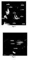
- FIG. 1 shows a sintered pore filled with oxide. There are individual oxide particles which are connected to one another. In FIG. 2 the oxide layer is reproduced near the edge zone. The oxide layer thickness is about 6 microns.
- FIG. 3 shows the EDX spectrum of an oxide particle formed in the sintering pore. The oxide is formed of Al, Cr and O. The C-peak is a measurement artifact. The element mapping does not resolve Al and Cr separately. The definition given in the description is therefore a
- FIG. 4 Returns the EDX spectrum for a measurement point in the area of the matrix material.
- the Al content of the matrix material is below the detection limit due to the oxidation treatment.
- the matrix material contains only Cr and Fe according to the alloy composition.
- the C-peak is again a measurement artifact.
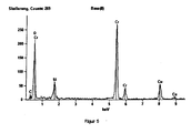
- FIG. 5 shows the EDX spectrum of the outer oxide layer.
- the oxide layer contains no Al. In addition to Cr and O, only Si is detectable.
- the Cr powder used had an Si content of 0.052% by weight.
- the Si content does not adversely affect the long-term behavior.
- the Cu and C peaks are measurement artifacts.
- the interconnectors of the invention have an excellent dimensional stability and an air permeability of ⁇ 3x10 -4 Pa.
Landscapes
- Chemical & Material Sciences (AREA)
- Engineering & Computer Science (AREA)
- General Chemical & Material Sciences (AREA)
- Sustainable Energy (AREA)
- Manufacturing & Machinery (AREA)
- Chemical Kinetics & Catalysis (AREA)
- Electrochemistry (AREA)
- Life Sciences & Earth Sciences (AREA)
- Sustainable Development (AREA)
- Organic Chemistry (AREA)
- Composite Materials (AREA)
- Materials Engineering (AREA)
- Mechanical Engineering (AREA)
- Metallurgy (AREA)
- Inorganic Chemistry (AREA)
- Fuel Cell (AREA)
- Powder Metallurgy (AREA)
Description
- Die Erfindung betrifft einen Interkonnektor einer Festelektrolyt-Hochtemperatur-Brennstoffzelle aus einer gesinterten, Sinterporen aufweisenden Chromlegierung mit Cr > 90 Gew.%, 3 bis 8 Gew.% Fe und optional 0,001 bis 2 Gew.% zumindest eines Elements der Gruppe der Seltenerdmetalle. Die Erfindung betrifft weiters ein Verfahren zur Herstellung eines Interkonnektors sowie eine Festelektrolyt-Hochtemperatur-Brennstoffzelle, die einen Interkonnektor enthält.
- Der metallische Interkonnektor (auch als bipolare Platte oder Stromsammler bezeichnet) ist eine essentielle Komponente einer Festelektrolyt-Hochtemperatur-Brennstoffzelle (auch als Festoxid-Brennstoffzelle, Hochtemperatur-Brennstoffzelle oder SOFC (Solid Oxide Fuel Cell) bezeichnet).
- Eine Festelektrolyt-Hochtemperatur-Brennstoffzelle wird üblicherweise bei einer Betriebstemperatur von 650°C bis 1.000°C betrieben. Der Elektrolyt besteht aus einem festen keramischen Werkstoff, der in der Lage ist, Sauerstoffionen zu leiten, für Elektronen jedoch isolierend wirkt. In K. Wincewicz, J. Cooper, "Taxonomies of SOFC material and manufacturing alternatives", Journal of Power Sources (2005) sind als Elektrolytwerkstoffe mit Yttrium, Scandium oder Kalzium dotiertes Zirkonoxid (YSZ, SSZ oder CSZ), dotiertes Lanthanoxid und dotiertes Ceroxid beschrieben. Für Kathode und Anode werden Ionen und Elektronen leitende Keramiken eingesetzt, wie beispielsweise mit Strontium dotiertes Lanthanmanganat (LSM) für die Kathode und ein Nickel-YSZ (oder SSZ, CSZ) Cermet für die Anode.
- Der Interkonnektor ist zwischen den einzelnen Zellen angeordnet, wobei Zellen, optional vorhandene Kontaktschichten und Interkonnektoren zu einem Stack gestapelt werden. Der Interkonnektor verbindet die einzelnen Zellen in Serie und sammelt so die in den Zellen erzeugte Elektrizität. Zudem unterstützt er die Zellen mechanisch und sorgt für eine Trennung und Führung der Reaktionsgase auf der Anoden- und Kathodenseite. Der Interkonnektor ist sowohl oxidierendem als auch reduzierendem Milieu bei hohen Temperaturen ausgesetzt. Dies erfordert eine entsprechend hohe Korrosionsbeständigkeit. Zudem muss der thermische Ausdehnungskoeffizient des Interkonnektors von Raumtemperatur bis zur maximalen Einsatztemperatur gut an den thermischen Ausdehnungskoeffizienten des Elektrolyt-, Anoden- und Kathodenwerkstoffs angepasst sein. Weitere Forderungen sind Gasdichtheit, eine hohe, konstante Elektronenleitfähigkeit sowie eine möglichst hohe thermische Leitfähigkeit bei Einsatztemperatur.
- Generell finden in verschiedensten Hochtemperaturanwendungen im Hinblick auf gute Hochtemperatur-Korrosionseigenschaften vorwiegend Aluminiumoxid und Chromoxid bildende Legierungen, teilweise mit Anteilen an Silizium, Verwendung. Aufgrund der mangelnden elektronischen Leitfähigkeit von Al2O3 und SiO2 werden für Interkonnektoren in Festelektrolyt-Hochtemperatur-Brennstoffzellen bevorzugt Chromoxid bildende Legierungen vorgeschlagen. Ein sehr gut angepasstes thermisches Ausdehnungsverhalten, verbunden mit hoher Korrosionsbeständigkeit, weisen dabei Chrom-Eisen-Legierungen auf. Die Korrosionsbeständigkeit kann durch Zugabe von Yttrium weiter verbessert werden. Eine Chromlegierung mit 5 bis 50 Gew.% Fe und einem Seltenerdoxid eines Metalls aus der Gruppe Y, La, Ce, Nd mit einer Partikelgröße von 1 bis 10 µm ist in der
JP-A-02258946 - Die
EP-A-0 510 495 beschreibt unter anderem einen oxiddispersionsverfestigten, wärmebeständigen, gesinterten Werkstoff, der 0,2 bis 2 Gew.% Y2O3 in feindisperser Form mit einer Partikelgröße von maximal 0,1 µm enthält, wobei der Matrixwerkstoff unter anderem auch aus einem Chrom-Basiswerkstoff mit 0 bis 20 Gew.% Fe und 0 bis 10 Gew.% eines Elements der Gruppe Al, Mo, W, Nb, Ta, Hf und Al-Ti bestehen kann. Fe wird zur Erhöhung der Sinterfähigkeit beigegeben. Al liegt zur Festigkeitssteigerung in ausgeschiedener intermetallischer Form in der Matrix vor. Die Herstellung erfolgt durch mechanisches Legieren, wobei als Verdichtungsprozess nur druckunterstützte Sinterprozesse angeführt sind, nämlich Heißpressen, heißisostatisches Pressen und Heißpulverextrusion. - Die
EP-A-0 570 072 beschreibt eine Chromlegierung mit 0,005 bis 5 Gew.% zumindest eines Oxides der Gruppe der Seltenerdmetalle, 0,1 bis 32 Gew.% zumindest eines Metalls der Gruppe Fe, Ni und Co, bis zu 30 Gew.% zumindest eines Metalls der Gruppe Al, Ti, Zr, Hf, bis zu 10 Gew.% zumindest eines Metalls der Gruppe V, Nb, Mo, Ta, W, Re, bis zu 1 Gew.% zumindest eines Elements der Gruppe C, N, B und Si. Die Herstellung erfolgt über Pulvermischen, Pressen, Sintern, Einkannen der gesinterten Platte in Stahlblech und Warmwalzen der gekannten Platte. - Die Verwendung einer Cr-Fe Legierung für Brennstoffzellen geht erstmalig aus der
US 3,516,865 hervor. Der Cr-Gehalt liegt bei 15 bis 85 Gew.%. Optional kann die Legierung Y, Hf, Zr oder Th enthalten. DieEP-A-0 578 855 beschreibt eine metallische Komponente aus einer Chromlegierung mit 3 bis 10 At.% Fe sowie 0,5 bis 5 At.% Seltenerdmetall und/oder Seltenerdmetalloxid für Festelektrolyt-Hochtemperatur-Brennstoffzellen, die mit einem keramischen Festelektrolyten aus YSZ versehen sind. - Die
WO 95/026576 A1 - Da für die Einstellung eines definierten Strömungsverlaufs der Interkonnektor eine komplexe Oberflächengeometrie aufweist, sind pulvermetallurgische Verfahren vorteilhaft, welche die Endform ohne mechanische Nacharbeit erzeugen. So beschreibt die
WO 02/055747 A1 - Die
WO 2004/012885 A2 beschreibt ein Verfahren zur Herstellung eines Formteils, beispielsweise eines Interkonnektors, bestehend aus einem scheiben- oder plattenförmigen Grundkörper mit einer Vielzahl von noppen- und/oder stegförmigen Erhebungen, die mit geneigten Seitenflächen in den Grundkörper übergehen, durch endformnahes Pressen und Sintern pulverförmiger Ausgangsmaterialien, wobei die Formgebung in einem zweistufigen Pressvorgang erfolgt. Ein pulvermetallurgisches Verfahren, das zu Bauteilen mit Endkontur führt, ist nur bei geringem bis moderatem Sinterschwund möglich, da ein hoher Sinterschwund aufgrund von Schwankungen der physikalischen Pulvereigenschaften nicht mit ausreichender Konstanz einstellbar ist. Zudem ist eine Restporosität nach dem Sintervorgang günstig für den zweiten, die Endkontur gebenden Pressschritt. - Nach der
WO 2004/012885 A2 hergestellte Bauteile weisen daher eine Restporosität auf. Es ist nun bekannt, Sinterporen unter Bildung eines Oxids des Matrixwerkstoffes zu füllen. Dieser Prozess wird bei Produkten aus Sinterstahl Brünieren genannt. Dabei wird der gesinterte Bauteil in Wasserdampf unter Temperatur so behandelt, dass die Sinterporen mit Fe2O3 gefüllt werden. Ein Füllen der Sinterporen mit einem artgleichen Oxid kann auch bei Chromlegierungen angewandt werden. Es ist jedoch dabei nachteilig, dass das Füllen der Sinterporen von außen nach innen abläuft, wodurch mit der Prozesszeit die Sauerstoffpermeabilität in das Innere des Interkonnektors und damit ein gleichmäßiges Füllen zentrumsnaher Poren behindert wird. Zudem weist ein Interkonnektor typischerweise auf der Oberfläche eine Noppen- und/oder Stegstruktur auf, was unterschiedliche örtliche Wandstärken bedingt. Auch dies erschwert einen kostengünstigen und sicheren Prozess. - Aufgabe der gegenständlichen Erfindung ist es daher, einen Interkonnektor und ein Verfahren zur Herstellung eines Interkonnektors bereitzustellen, der einen an die Keramikkomponenten angepassten thermischen Ausdehnungskoeffizienten, eine hohe Formbeständigkeit, eine hohe Korrosionsbeständigkeit sowohl im reduzierenden als auch oxidierenden Milieu, eine hohe elektrische Leitfähigkeit im Bereich der Kontaktflächen zur Anode und Kathode sowie eine hohe Gasdichtheit aufweist und mit niedrigen Kosten hergestellt werden kann. Weiters ist es Aufgabe der Erfindung, eine Festelektrolyt-Hochtemperatur-Brennstoffzelle bereitzustellen, die einen aus stabilisiertem Zirkonoxid bestehenden keramischen Festelektrolyten und einen Interkonnektor mit dem zuvor genannten Eigenschaftsprofil umfasst.
- Die Aufgabe der Erfindung wird durch einen Interkonnektor gemäß Anspruch 1, eine Festelektrolyt-Hochtemperatur-Brennstoffzelle gemäß Anspruch 11 und durch ein Verfahren zur Herstellung eines Interkonnektors gemäß Anspruch 12 gelöst.
- Der Interkonnektor besteht dabei aus einer gesinterten Chromlegierung mit einem Chromgehalt von > 90 Gew.%, 3 bis 8 Gew.% Fe und optional 0,001 bis 2 Gew.% zumindest eines Elements der Gruppe der Seltenerdmetalle. Die Chromlegierung enthält 0,1 bis 2 Gew.% Al, wobei vorzugsweise mehr als 80 %, bevorzugt mehr als 90 % und besonders bevorzugt mehr als 99 % des Al in Form einer oxidischen, auch Cr enthaltenden Verbindung vorliegt. Der Rest des Al, wenn vorhanden, liegt in gelöster Form, in Form einer nichtoxidischen Verbindung oder in Form einer intermetallischen Phase vor. Vorzugsweise liegt der Gehalt an gelöstem Al bei kleiner 200 µg/g, bevorzugt bei kleiner 100 µg/g und besonders bevorzugt bei kleiner 50 µg/g.
- Bei der Bestimmung des Al Gehaltes wird unabhängig von der Bindungsform der Gesamt-Al-Gehalt im Interkonnektor berücksichtigt. Liegt der Al-Gehalt in der Chromlegierung unter 0,1 Gew.% wird nicht ausreichend Al in die Al und Cr enthaltende oxidische Verbindung eingebaut. Liegt der Al-Gehalt über 2 Gew.%, so bilden sich verstärkt auch an der Korngrenzen und im Korninneren Al enthaltende oxidische Ausscheidungen aus. Der bevorzugte Gehalt an Aluminium in der Chromlegierung beträgt 0,15 bis 0,5 Gew.%.
- Die gesinterte Chromlegierung enthält weiters Sinterporen, vorzugsweise 2 bis 20 Vol.%, bevorzugt 4 bis 15 Vol.%, wobei diese Sinterporen zumindest teilweise mit der Al und Cr enthaltenden oxidischen Verbindung gefüllt sind. Eine geringere Porosität kann nur durch einen hohen Sinterschwund erzielt werden. Ein hoher Sinterschwund erschwert die Einstellung enger Maßtoleranzen. Können enge Maßtoleranzen nicht erreicht werden, ist ein aufwändiges mechanisches Nacharbeiten erforderlich. Bei einem Interkonnektor mit einer Restporosität größer 20 Vol.% ist keine ausreichende Festigkeit und Stabilität des Bauteils gegeben. Zudem kann auch durch ein Füllen der Sinterporen mit der Al und Cr enthaltenden oxidischen Komponente keine ausreichend hohe Gasdichtheit erzielt werden.
- Das Füllen der Sinterporen mit der Al und Cr enthaltenden oxidischen Verbindung erfolgt durch eine Oxidationsbehandlung des gesinterten Bauteils. Die Oxidationsbehandlung kann dabei als separater Prozessschritt erfolgen oder in den Sinterprozess integriert sein. Das Auffüllen der Sinterporen erfolgt gleichmäßig und damit in einfacher und prozesszuverlässiger Art und Weise. Es bilden sich dabei Aluminium- und Chrom-haltige Oxide hauptsächlich im Bereich der Sinterporen und nur zu einem geringen Anteil an den Korngrenzen und im Korninneren. Die sich auf der äußeren Oberfläche des Interkonnektors bildende Oxidschicht enthält bevorzugt zumindest 90 Gew.% Chromoxid. Besonders bevorzugt enthält die äußere Oxidschicht zumindest 95 Gew.% Chromoxid. Bevorzugt liegt der Al-Gehalt in der äußeren Oxidschicht unter der Nachweisgrenze üblicher Analyseverfahren (0,1 bis 1 Gew.%). Das Chromoxid liegt dabei bevorzugt als Cr2O3 vor. Es bildet sich damit oberflächlich eine sehr gut leitende Oxidschicht aus. Dies gilt sowohl für eine Oxidschicht, die sich durch die Oxidationsbehandlung beim Herstellprozess, als auch im Langzeiteinsatz bildet. Damit ist es grundsätzlich nicht erforderlich, die durch die Oxidationsbehandlung beim Herstellprozess gebildete Oxidschicht zu entfernen. Wird eine metallisch blanke Oberfläche angestrebt, kann die Oxidschicht beispielsweise durch einen Strahlprozess entfernt werden.
- Bevorzugt liegt der Anteil der Al- und Cr-haltigen oxidischen Verbindung (bezogen auf den Gesamtgehalt der Al- und Cr-haltigen oxidischen Verbindung) in den Sinterporen bei größer 65 Vol.%, an den Korngrenzen bei kleiner 20 Vol.% und im Korninneren bei kleiner 15 Vol.%. Besonders bevorzugt liegt der Anteil der Al- und Cr-haltigen oxidischen Verbindung (bezogen auf den Gesamtgehalt der Al- und Cr-haltigen oxidischen Verbindung) in den Sinterporen bei größer 85 Vol.%, an den Korngrenzen bei kleiner 10 Vol.% und im Korninneren bei kleiner 5 Vol.%.
- Vorteilhaft weist die Al- und Cr-haltige oxidische Verbindung ein mittleres Al / Cr Verhältnis (Gehalte jeweils in At.%) von größer 1 auf. Ein bevorzugtes mittleres Al / Cr Verhältnis liegt bei größer 2 und ein besonders bevorzugtes Al / Cr Verhältnis bei größer 5. Wie im Ausführungsbeispiel beschrieben, konnte ein Al / Cr Verhältnis von bis zu 8,6 gemessen werden.
- Vorteilhafterweise erfolgt die Oxidationsbehandlung des Bauteils bei einer Temperatur T, mit 700°C < T < 1.200°C. Unterhalb 700°C ist die Reaktionsgeschwindigkeit gering. Oberhalb 1.200°C bildet sich bereits in nennenswertem Ausmaß sechswertiges Chromoxid.
- Durch die Ausbildung der Al- und Cr-haltigen oxidischen Verbindung ist ein gleichmäßiges Füllen der Poren über den Querschnitt des Interkonnektors gewährleistet. Damit werden eine weitere innere Oxidation und ein Ausdehnen des Interkonnektors während des Betriebes der Festelektrolyt-Hochtemperatur-Brennstoffzelle vermieden. Somit ist gewährleistet, dass es beim Betrieb der Festelektrolyt-Hochtemperatur-Brennstoffzelle zu keiner Beschädigung, wie zum Beispiel Bruch, der keramischen Zellbauteile im Stackverbund kommt.
- Die Al und Cr enthaltende oxidische Verbindung besteht bevorzugt aus Al, Cr und O, Rest typische Verunreinigungen. Vorteilhaft ist es dabei, wenn die Al und Cr enthaltende oxidische Verbindung als Mischoxid vorliegt. In diesem Zusammenhang wird unter Mischoxid nicht nur ein Oxid verstanden, in dem die einzelnen Komponenten vollständig ineinander gelöst vorliegen, sondern auch solche Oxide, bei denen mit hochauflösenden Analyseverfahren, wie beispielsweise analytischem TEM, die einzelnen Komponenten nicht mehr getrennt auflösbar sind. Als bevorzugte oxidische Verbindung ist dabei ein xAl2O3·yCr2O3 zu nennen. Die bevorzugten Stöchiometriefaktoren x und y ergeben sich dabei aus den zuvor genannten Al / Cr Werten. Um eine ausreichende Gasdichtheit und Formstabilität des Interkonnektors während der gesamten Betriebsdauer der Festelektrolyt-Hochtemperatur-Brennstoffzelle zu gewährleisten, ist es vorteilhaft, wenn zumindest 50 % des Gesamtsinterporenvolumens der Chromlegierung mit der Al und Cr enthaltenden oxidischen Verbindung gefüllt sind. Die 50 Vol.% stellen dabei einen mittleren Wert dar. Es können dabei einzelne Poren mit einem geringeren Volumengehalt an oxidischer Verbindung gefüllt sein, ohne dass die Funktionsfähigkeit des Bauteils dadurch beeinträchtigt wird. Poren mit einem geringeren Füllgrad sind insbesondere solche, die keine offene Verbindung zur Oberfläche aufweisen. Diese Poren bleiben jedoch auch im Langzeiteinsatz stabil und sind daher sowohl für die Gasdichtheit als auch für die Formbeständigkeit unkritisch. Bevorzugt liegt das mit der Al und Cr enthaltenden oxidischen Verbindung gefüllte Gesamtsinterporenvolumen bei größer 75 %, besonders bevorzugt bei größer 90 %.
- Durch die Oxidationsbehandlung bildet sich vorzugsweise mehr als 80 %, bevorzugt mehr als 90 % und besonders bevorzugt mehr als 99 % des in der Chromlegierung enthaltenen Aluminiums in Form der oxidischen Verbindung aus. Es ist dabei nicht von Belang, in welcher Form das Al im Pulveransatz vorliegt. So können beispielsweise Chrom-Pulver verarbeitet werden, bei denen Al als Al203, als metallisches Al oder metallisches Al und Al203 vorliegt.
- Für das Korrosionsverhalten der Chromlegierung ist es weiters vorteilhaft, wenn diese 0,001 bis 2 Gew.% zumindest eines Elements der Gruppe der Seltenerdmetalle enthält. Die Seltenerdmetalle können dabei in gelöster oder gebundener Form, vorzugsweise in oxidischer Form, vorliegen. Die besten Resultate können erzielt werden, wenn die Legierung 0,005 bis 0,5 Gew.% Yttrium enthält. Yttrium kann in gelöster metallischer Form und / oder in Form von Yttriumoxid und / oder in Form von Yttriummischoxid vorliegen. Als bevorzugte Yttriummischoxide sind solche aus Basis von Al-Y und / oder Al-Cr-Y zu nennen. Die Zugabe von Yttrium ist auch für das Einhalten enger Maßtoleranzen vorteilhaft, da Yttrium die Sinterfähigkeit der Chromlegierung reduziert. Dies ist insofern von Bedeutung, da es damit möglich ist, bei hohen Temperaturen zu sintern, ohne dass dabei nennenswerter Sinterschwund auftritt. Ein hoher Sinterschwund würde sich zwar günstig auf die Gasdichtheit und die Korrosionsbeständigkeit des Interkonnektors auswirken, hätte jedoch einen negativen Einfluss auf die Möglichkeit endkonturnahe Bauteile herzustellen. Durch die hohe Sintertemperatur kann eine ausgezeichnete Homogenisierung der Chromlegierung erreicht werden. Es ist davon auszugehen, dass durch Y-haltige Ausscheidungen sowohl die Korngrenzendiffusionsgeschwindigkeit, als auch die Leerstellenerzeugung durch Quergleiten von Versetzungen erniedrigt werden.
- Weiters kann die Chromlegierung bis 3 Gew.% von weiteren in der Chromlegierung nicht löslichen Komponenten und bis 1 Gew.% von weiteren in der Chromlegierung löslichen Komponenten enthalten, ohne dass die Einsatzeigenschaften unzulässig verschlechtert werden. Bevorzugt liegt der Gehalt an weiteren nicht löslichen Komponenten bei < 1 Gew.% und der der Gehalt an weiteren löslichen Komponenten bei < 0,1 Gew.%. Als Beispiel für eine nicht lösliche Komponente ist Si zu nennen.
- Vorzugsweise weist daher die Chromlegierung folgende Zusammensetzung auf:
- Cr > 90 Gew.%;
- 3 bis 8 Gew.% Fe;
- 0,1 bis 2 Gew.% Al;
- Optional 0,001 bis 2 Gew.% zumindest eines Elements der Gruppe der Seltenerdmetalle;
- Optional bis 3 Gew.% zumindest einer weiteren in der Chromlegierung nicht löslichen Komponente;
- Optional bis 1 Gew.% zumindest einer weiteren in der Chromlegierung löslichen Komponente;
- Rest Sauerstoff und Verunreinigungen.
- Bevorzugt weist die Chromlegierung folgende Zusammensetzung auf:
- Cr > 90 Gew.%;
- 3 bis 8 Gew.% Fe;
- 0,1 bis 2 Gew.% Al;
- Optional 0,001 bis 2 Gew.% zumindest eines Elements der Gruppe der Seltenerdmetalle;
- Optional bis 1 Gew.% zumindest einer weiteren in der Chromlegierung nicht löslichen Komponente;
- Optional bis 0,1 Gew.% zumindest einer weiteren in der Chromlegierung löslichen Komponente;
- Rest Sauerstoff und Verunreinigungen.
- Besonders bevorzugt weist die Chromlegierung folgende Zusammensetzung auf:
- Cr > 90 Gew.%;
- 3 bis 8 Gew.% Fe;
- 0,1 bis 2 Gew.% Al;
- 0,005 bis 0,5 Gew.% Y;
- Rest Sauerstoff und Verunreinigungen.
- Der erfindungsgemäße Interkonnektor kann vorteilhaft in einer Festelektrolyt-Hochtemperatur-Brennstoffzelle eingesetzt werden, die einen Festelektrolyten aus stabilisiertem Zirkonoxid aufweist. Das Zirkonoxid kann dabei gemäß dem Stand der Technik mit Yttrium, Kalzium oder Scandium stabilisiert sein. Als Kathode können die üblichen keramischen Kathodenwerkstoffe, wie beispielsweise mit Strontium dotiertes Lanthanmanganat, verwendet werden. Auch bei der Anode kann auf bewährte Werkstoffe, wie beispielsweise Cermet-Werkstoffe bestehend aus Nickel und stabilisiertem Zirkonoxid, zurückgegriffen werden.
- Bei der Herstellung der Interkonnektoren kann unter anderem auf die pulvermetallurgischen Verfahren oder einzelne Verfahrensschritte, wie in der
WO 02/055747 A1 WO 2004/012885 A2 beschrieben, zurückgegriffen werden. Als Cr Pulver eignet sich besonders Pulver mit einer laseroptisch gemessenen Korngröße von < 200 µm, bevorzugt von < 160 µm. Das Cr Pulver enthält bevorzugt Al in metallischer Form und gebunden als Al2O3. Der Al Gehalt (Summe metallisches und gebundenes Al) liegt bevorzugt bei 2.000 bis 10.000 µg/g, der Si-Gehalt bei < 700 µg/g. Bevorzugt wird weiters ein elementares Fe Pulver oder ein Fe-Y Vorlegierungspulver verwendet. Das Fe-Y Vorlegierungspulver wird bevorzugt durch einen Verdüsungsprozess hergestellt. Es können jedoch auch Cr-Fe oder Cr-Fe-Y Vorlegierungspulver verwendet werden. Die einzelnen Pulverbestandteile werden unter Zugabe eines üblichen Presshilfsmittels in Zwangs- oder Diffusionsmischern gemischt. Der gemischte Pulveransatz wird in eine Pressmatrize gefüllt und bei einem Pressdruck p, mit 500 < p < 1000 MPa, formgebend verdichtet. Nach dem Pressvorgang erfolgt ein Sinterschritt in reduzierender Atmosphäre bei einer Temperatur T, mit 1200°C < T < Solidus Temperatur. Dabei erfolgt das Entbindern des Grünlings als integrativer Bestandteil des Sinterschritts oder als separater Prozessschritt. - Alternativ kann nach dem Pressen der Grünling bevorzugt bei einer Temperatur T, mit 700°C < T < 1200°C, in reduzierender Atmosphäre vorgesintert werden. Dabei erfolgt das Entbindern des Grünlings als integrativer Bestandteil des Vorsinterschritts oder als separater Prozessschritt. Der vorgesinterte Teil wird einem Nachpressen bei einem Pressdruck p, mit 500 < p < 1000 MPa, unterzogen. Das Nachpressen ist als Kalibrierpressen ausgeführt und erzeugt die Endkontur des Interkonnektors. Da durch den Vorsinterprozess die Festigkeit der Chromlegierung reduziert wird, kann durch den Nachpressvorgang eine weitere Verdichtung erreicht werden. Nach dem Nachpressvorgang erfolgt ein Sinterschritt in reduzierender Atmosphäre bei einer Temperatur T, mit 1200°C < T < Solidus Temperatur. Bevorzugt kann dieser zweistufige Pressvorgang gemäß dem in der
WO 2004/012885 offenbarten Verfahren erfolgen. - In einem nächsten Schritt wird der Bauteil einer oxidierenden Behandlung bevorzugt bei einer Temperatur T, mit 700°C < T < 1.200°C unterzogen. Die oxidierende Behandlung kann dabei beispielsweise an Luft oder Sauerstoff erfolgen. Die Behandlungszeit wird bevorzugt so gewählt, dass bei einer gravimetrischen Untersuchung > 85 % der bei der jeweiligen Temperatur sich bei einer Oxidationszeit von 24 h einstellenden Gewichtszunahme erzielt wird. In einem weiteren Prozessschritt kann der oxidierte Bauteil einem Sandstrahlprozess unterzogen werden, wodurch die auf der Oberfläche vorliegenden Oxide entfernt werden.
- Die bevorzugte Herstellmethode kann damit folgendermaßen zusammengefasst werden:
- Herstellen eines Pulveransatzes unter Verwendung von gemischtem, teilweise vorlegiertem und/oder vollständig vorlegiertem Pulver;
- Formgebendes Matrizenpressen mit einem Pressdruck p, mit 500 < p < 1000 MPa;
- Optional Vorsintern bei einer Temperatur T, mit 700°C < T < 1200°C in reduzierender Atmosphäre und optional Kalibrierpressen bei einem Pressdruck p, mit 500 < p < 1000 MPa;
- Sintern bei einer Temperatur T, mit 1200°C < T < Solidus Temperatur in reduzierender Atmosphäre;
- Oxidierende Behandlung bevorzugt bei einer Temperatur T, mit 700°C < T < 1.200°C;
- Optional Sandstrahlen
- Die Formgebung des Interkonnektors kann auch durch andere geeignete Verfahren, wie beispielsweise Metallpulverspritzguss, erfolgen. Auch Pulvergießen und Pulverextrusion gefolgt von einem Prägeschritt sind geeignete Herstellverfahren.
- Im Folgenden wird die Erfindung durch ein Herstellungsbeispiel näher erläutert.
- Beispiel:
- Figur 1:
- Gesinterter, oxidierter Interkonnektor gemäß Herstellbeispiel, Zentrumsprobe, TEM Hellfeldbild, Sinterpore gefüllt mit Al- und Cr-haltigem Oxid, gekennzeichnete EDX Analysepunkte.
- Figur 2:
- Gesinterter, oxidierter Interkonnektor gemäß Herstellbeispiel, Randprobe, TEM Hellfeldbild, äußere Oxidschicht, gekennzeichnete EDX Analysepunkte.
- Figur 3:
- EDX Spektrum für Analysepunkt "Base (1)" gemäß
Figur 1 (Al- und Cr-haltiges Oxid in Sinterpore). - Figur 4:
- EDX Spektrum für Matrixwerkstoff, Zentrumsprobe.
- Figur 5:
- EDX Spektrum für Analysepunkt "Base (8)" gemäß
Figur 2 (äußere Oxidschicht). - Ein scheibenförmiger Interkonnektor mit einem Durchmesser von 120 mm, einer Gesamtdicke von 2,5 mm und einem Durchmesser der Mittelbohrung von 8,8 mm mit auf einer Seite des Grundkörpers stegförmigen Erhebungen mit etwa 0,5 mm Höhe und 5 mm Breite sowie auf der gegenüber liegenden Seite angeordneten stegförmigen Erhebungen mit etwa 0,7 mm Höhe und 5 mm Breite, dazwischen in regelmäßigen Abständen und Reihen angeordneten noppenförmigen Erhebungen wurde mit Endkontur hergestellt. Dafür wurde zunächst ein Pulveransatz bestehend aus 95 Gew.% Chrompulver mit einem Al-Gehalt von 0,181 Gew.% sowie 5 Gew.% eines Vorlegierungspulvers aus Eisen mit 0,05 Gew.% Yttrium unter Zugabe von 1 Gew.% Mikrowachs als Presshilfsmittel angefertigt. Die verwendeten Pulver wiesen Korngrößen im Bereich von 36 bis 160 µm auf. Der Pulveransatz wurde formgebend durch Matrizenpressen mit 800 MPa verdichtet. Danach wurde der Grünling bei 1.000°C 3 Stunden in Wasserstoff vorgesintert. Das Kalibrierpressen des vorgesinterten Bauteils erfolgte in einem zweiten Presswerkzeug. Dabei wurde die Matrize maßlich derart angepasst, dass nach dem zweiten Pressschritt der Interkonnektor die Endform aufwies. Die Ausgestaltung der Presswerkzeuge erfolgte gemäß der
WO 2004/012885 A2 . Danach wurde der Bauteil bei 1.450°C 2 Stunden in Wasserstoff gesintert. - Anschließend wurde der Bauteil einer Voroxidation unterzogen, wobei diese bei einer Temperatur von 950°C für 18 Stunden an Luft erfolgte.
- Der so hergestellte Interkonnektor wies eine mittlere Dichte von 6,61 g/cm3 (Mittelwert aus 15 Proben) auf. Zentrumsproben (bezogen auf den Querschnitt des Interkonnektors) randnahe und Randproben wurden mittels Ionendünnen (FIB - Focused Ion Beam) für die Untersuchung an einem analytischem TEM (Philips CM-20) präpariert. Die Analyse erfolgte mittels energiedispersiver Röntgenanalyse (EDX). Die morphologische Untersuchung wurde an einem Rasterelektronenmikroskop durchgeführt, mit dem Ergebnis, dass die Poren gleichmäßig mit Oxid gefüllt sind.
- Im Folgenden sind die Ergebnisse der translektronenmikroskopischen Untersuchung und EDX Analysen zusammengefasst.
Figur 1 zeigt eine mit Oxid gefüllte Sinterpore. Es liegen dabei einzelne Oxidteilchen vor, die miteinander verbunden sind. InFigur 2 ist die Oxidschicht im Bereich der Randzone wiedergegeben. Die Oxidschichtdicke beträgt ca. 6 µm.Figur 3 zeigt das EDX Spektrum eines Oxidteilchen, das sich in der Sinterpore gebildet hat. Das Oxid ist aus Al, Cr und O gebildet. Der C-Peak ist ein Messartefakt. Das Elementmapping löst Al und Cr nicht getrennt auf. Nach der in der Beschreibung wiedergegebenen Definition handelt es sich daher um ein - Al-Cr Mischoxid. Das berechnete Al / Cr (At.% / At.%) Verhältnis beträgt 6,9. Die weitere Untersuchung von Oxidteilchen in Sinterporen erbrachte in jedem Fall ein Al-reiches Al-Cr Mischoxid, wobei der niedrigste Al / Cr (At.% / At.%) Wert bei 4,7 und der höchste Al / Cr (At.% / At.%) Wert bei 8,6 liegt. Vereinzelt konnten auch Oxide an den Korngrenzen und im Korninneren detektiert werden, wobei diese ebenfalls Al und Cr mit einem hohen Al / Cr Verhältnis aufwiesen.
Figur 4 gibt das EDX Spektrum für einen Messpunkt im Bereich des Matrixwerkstoffs wieder. Der Al-Gehalt des Matrixwerkstoffs ist durch die Oxidationsbehandlung unter der Nachweisgrenze. Der Matrixwerkstoff enthält nur Cr und Fe entsprechend der Legierungszusammensetzung. Der C-Peak ist wiederum ein Messartefakt. -
Figur 5 zeigt das EDX Spektrum der äußeren Oxidschicht. Die Oxidschicht enthält kein Al. Neben Cr und O ist nur noch Si detektierbar. Das verwendete Cr Pulver wies einen Si-Gehalt von 0,052 Gew.% auf. - Der Si Gehalt wirkt sich dabei nicht nachteilig auf das Langzeitverhalten aus. Die Cu und C Peaks sind Messartefakte.
- Die erfindungsgemäßen Interkonnektoren weisen eine ausgezeichnete Formstabilität und eine Luft-Permeabilität von < 3x10⁻⁴ Pa auf.
Claims (12)
- Interkonnektor für eine Festelektrolyt-Hochtemperatur-Brennstoffzelle aus einer gesinterten, Sinterporen aufweisenden Chromlegierung mit Cr > 90 Gew.%; 3 bis 8 Gew.% Fe; und optional 0,001 bis 2 Gew.% zumindest eines Elements der Gruppe der Seltenerdmetalle;
dadurch gekennzeichnet,
dass die Chromlegierung 0,1 bis 2 Gew.% Al enthält, wobei die Sinterporen zumindest teilweise mit einer Al und Cr enthaltenden oxidischen Verbindung gefüllt sind. - Interkonnektor nach Anspruch 1, dadurch gekennzeichnet, dass das Al / Cr (At.% / At.%) Verhältnis der Al und Cr enthaltenden oxidischen Verbindung größer 1 beträgt.
- Interkonnektor nach Anspruch 2, dadurch gekennzeichnet, dass das Al / Cr (At.% / At.%) Al Verhältnis der Al und Cr enthaltenden oxidischen Verbindung größer 2 beträgt.
- Interkonnektor nach einem der Ansprüche 1 bis 3, dadurch gekennzeichnet, dass die Al und Cr enthaltende oxidische Verbindung ein Al-Cr Mischoxid ist.
- Interkonnektor nach einem der Ansprüche 1 bis 4, dadurch gekennzeichnet, dass die Al und Cr enthaltende oxidische Verbindung ein xAl2O3·yCr2O3 ist.
- Interkonnektor nach einem der Ansprüche 1 bis 5, dadurch gekennzeichnet, dass die Chromlegierung 2 bis 20 Vol.% Sinterporen enthält.
- Interkonnektor nach einem der Ansprüche 1 bis 6, dadurch gekennzeichnet, dass zumindest 50 Vol.% des Gesamtsinterporenvolumens der Chromlegierung mit der Al und Cr enthaltenden oxidischen Verbindung gefüllt ist.
- Interkonnektor nach einem der Ansprüche 1 bis 7, dadurch gekennzeichnet, dass < 0,05 Gew.% Al in der Matrix der Chromlegierung gelöst ist und / oder als intermetallische Phase vorliegt.
- Interkonnektor nach einem der Ansprüche 1 bis 8, dadurch gekennzeichnet, dass die Chromlegierung 0,005 bis 0,5 Gew.% Y enthält.
- Interkonnektor nach einem der Ansprüche 1 bis 9, dadurch gekennzeichnet, dass die äußere Oberfläche oxidfrei ist oder eine Oxidschicht aufweist, die zumindest 90 Gew.% Chromoxid enthält.
- Festelektrolyt-Hochtemperatur-Brennstoffzelle, die einen aus stabilisiertem Zirkonoxid bestehenden keramischen Festelektrolyten und einen Interkonnektor nach einem der Ansprüche 1 bis 10 umfasst.
- Verfahren zur Herstellung eines Interkonnektors nach einem der Ansprüche 1 bis 10, dadurch gekennzeichnet, dass dieses die folgenden Verfahrenschritte umfasst:- Herstellen eines Pulveransatzes unter Verwendung von gemischtem, teilweise vorlegiertem und/oder vollständig vorlegiertem Pulver;- Formgebendes Matrizenpressen mit einem Pressdruck p, mit 500 < p < 1000 MPa;- Optional Vorsintern bei einer Temperatur T, mit 700°C < T < 1200°C in reduzierender Atmosphäre und optional Kalibrierpressen bei einem Pressdruck p, mit 500 < p < 1000 MPa;- Sintern bei einer Temperatur T, mit 1200°C < T < Solidus Temperatur in reduzierender Atmosphäre;- Oxidierende Behandlung bevorzugt bei einer Temperatur T, mit 700°C<T<1.200°C;- Optional Sandstrahlen.
Applications Claiming Priority (1)
| Application Number | Priority Date | Filing Date | Title |
|---|---|---|---|
| AT0014609U AT11555U1 (de) | 2009-03-12 | 2009-03-12 | Interkonnektor einer festelektrolyt-hochtemperatur-brennstoffzelle |
Publications (2)
| Publication Number | Publication Date |
|---|---|
| EP2230707A1 EP2230707A1 (de) | 2010-09-22 |
| EP2230707B1 true EP2230707B1 (de) | 2011-03-23 |
Family
ID=42244377
Family Applications (1)
| Application Number | Title | Priority Date | Filing Date |
|---|---|---|---|
| EP10002472A Active EP2230707B1 (de) | 2009-03-12 | 2010-03-10 | Interkonnektor einer Festelektrolyt-Hochtemperatur-Brennstoffzelle |
Country Status (10)
| Country | Link |
|---|---|
| US (1) | US9029044B2 (de) |
| EP (1) | EP2230707B1 (de) |
| JP (1) | JP5497493B2 (de) |
| KR (1) | KR101681326B1 (de) |
| CN (1) | CN101834298B (de) |
| AT (2) | AT11555U1 (de) |
| CA (1) | CA2695062C (de) |
| DE (1) | DE502010000009D1 (de) |
| DK (1) | DK2230707T3 (de) |
| ES (1) | ES2358971T3 (de) |
Families Citing this family (21)
| Publication number | Priority date | Publication date | Assignee | Title |
|---|---|---|---|---|
| US10040121B2 (en) * | 2009-12-09 | 2018-08-07 | Porite Taiwan Co., Ltd. | Method for forming an interconnect of a solid oxide fuel cell |
| US8840833B1 (en) | 2010-11-30 | 2014-09-23 | Bloom Energy Corporation | Iron coated chromium powder and SOFC IC made therefrom |
| US20150221957A1 (en) * | 2011-11-18 | 2015-08-06 | Bloom Energy Corporation | Method of making fuel cell interconnect using powder metallurgy |
| US8962219B2 (en) * | 2011-11-18 | 2015-02-24 | Bloom Energy Corporation | Fuel cell interconnects and methods of fabrication |
| US11114677B2 (en) | 2012-07-09 | 2021-09-07 | Stackpole International Powder Metal, Ulc | Fuel cell interconnector and method for making a fuel cell interconnector |
| US9847520B1 (en) | 2012-07-19 | 2017-12-19 | Bloom Energy Corporation | Thermal processing of interconnects |
| JP5816314B2 (ja) | 2013-03-29 | 2015-11-18 | 本田技研工業株式会社 | 燃料電池用セパレータ及びその製造方法 |
| AT513501B1 (de) * | 2013-09-02 | 2014-05-15 | Abatec Group Ag | IR-Strahler mit Doppelverglasung |
| AT13692U1 (de) * | 2013-09-02 | 2014-06-15 | Plansee Se | Chrom-haltiges Pulver oder Pulvergranulat |
| AT14143U1 (de) * | 2013-09-02 | 2015-05-15 | Plansee Se | Pulvermetallurgisches Bauteil |
| WO2015050855A1 (en) | 2013-10-01 | 2015-04-09 | Bloom Energy Corporation | Pre-formed powder delivery to powder press machine |
| US10079393B1 (en) * | 2014-01-09 | 2018-09-18 | Bloom Energy Corporation | Method of fabricating an interconnect for a fuel cell stack |
| WO2015130644A1 (en) | 2014-02-25 | 2015-09-03 | Bloom Energy Corporation | Composition and processing of metallic interconnects for sofc stacks |
| US9992917B2 (en) | 2014-03-10 | 2018-06-05 | Vulcan GMS | 3-D printing method for producing tungsten-based shielding parts |
| CN105562698B (zh) * | 2014-10-17 | 2018-09-04 | 东睦新材料集团股份有限公司 | 一种粉末冶金铬合金燃料电池连接件的封孔方法 |
| US20180085829A1 (en) * | 2016-09-28 | 2018-03-29 | Hamilton Sundstrand Corporation | Adjusting porosity in powder metal articles |
| CN107146898A (zh) * | 2017-05-31 | 2017-09-08 | 安徽理工大学 | 一种质子交换模燃料电池金属双极板湿磨温压烧结方法 |
| CN111403768B (zh) * | 2020-03-31 | 2021-05-18 | 西安交通大学 | 一体化结构、电池/电解池及电池堆的制备方法 |
| JP7809627B2 (ja) * | 2022-03-26 | 2026-02-02 | ブルーム エネルギー コーポレイション | 大きな設置面積の固体酸化物形燃料電池コラムにおいて熱により誘発される応力亀裂を防止する方法及び装置 |
| WO2025137173A1 (en) * | 2023-12-18 | 2025-06-26 | Hall Labs Llc | Solid oxide fuel cell stacks and methods of making |
| CN121484109A (zh) * | 2026-01-09 | 2026-02-06 | 东睦新材料集团股份有限公司 | 一种固体氧化物燃料电池连接板的制造方法 |
Family Cites Families (23)
| Publication number | Priority date | Publication date | Assignee | Title |
|---|---|---|---|---|
| US3516865A (en) | 1967-08-30 | 1970-06-23 | Gen Electric | Electrochemical cell including iron-chromium alloy conductor connected to cathode |
| JPH0832942B2 (ja) | 1989-03-30 | 1996-03-29 | 株式会社クボタ | 複合焼結合金、耐熱部材および加熱炉内鋼材支持部材 |
| EP0423448A1 (de) | 1989-09-20 | 1991-04-24 | Asea Brown Boveri Ag | Stromkollektor zur Stromleitung zwischen stapelförmig angeordneten Hochtemperatur-Brennstoffzellen und Verfahren zu dessen Herstellung |
| US5427601A (en) * | 1990-11-29 | 1995-06-27 | Ngk Insulators, Ltd. | Sintered metal bodies and manufacturing method therefor |
| JPH0747793B2 (ja) * | 1991-04-26 | 1995-05-24 | 株式会社クボタ | 酸化物分散強化耐熱焼結合金 |
| AT399165B (de) | 1992-05-14 | 1995-03-27 | Plansee Metallwerk | Legierung auf chrombasis |
| DE59206124D1 (de) | 1992-07-16 | 1996-05-30 | Siemens Ag | Material für die metallischen Komponenten von Hochtemperatur-Brennstoffzellen-Anlagen |
| DE4410711C1 (de) | 1994-03-28 | 1995-09-07 | Forschungszentrum Juelich Gmbh | Metallische bipolare Platte für HT-Brennstoffzellen und Verfahren zur Herstellung desselben |
| JPH08188844A (ja) | 1995-01-09 | 1996-07-23 | Daido Steel Co Ltd | 酸化物分散強化型耐熱合金 |
| JPH0963605A (ja) | 1995-08-18 | 1997-03-07 | Fuji Electric Co Ltd | 固体電解質型燃料電池 |
| AUPN876896A0 (en) | 1996-03-18 | 1996-04-18 | Ceramic Fuel Cells Limited | An electrical interconnect for a planar fuel cell |
| JPH1017958A (ja) | 1996-07-05 | 1998-01-20 | Daido Steel Co Ltd | 酸化物分散強化型クロム基合金の製造方法 |
| DE19705874C2 (de) * | 1997-02-15 | 2000-01-20 | Forschungszentrum Juelich Gmbh | Stromkollektor für SOFC-Brennstoffzellenstapel |
| AT4737U1 (de) | 2001-01-15 | 2001-11-26 | Plansee Ag | Pulvermetallurgisches verfahren zur herstellung hochdichter formteile |
| JP2003027205A (ja) * | 2001-07-09 | 2003-01-29 | Showa Denko Kk | 溶射材料の製造方法 |
| DE10161538B4 (de) | 2001-12-10 | 2004-09-09 | Deutsches Zentrum für Luft- und Raumfahrt e.V. | Träger für eine elektrochemische Funktionseinheit einer Hochtemperatur-Brennstoffzelle und Hochtemperatur-Brennstoffzelle |
| CA2429899A1 (en) | 2002-05-29 | 2003-11-29 | Sanyo Electric Co., Ltd. | Solid oxide fuel cell |
| AT6260U1 (de) | 2002-08-01 | 2003-07-25 | Plansee Ag | Verfahren zur herstellung eines formteiles |
| US7951510B2 (en) * | 2004-11-11 | 2011-05-31 | GM Global Technology Operations LLC | Electroconductive polymer coating on electroconductive elements in a fuel cell |
| KR100924700B1 (ko) * | 2005-01-12 | 2009-11-03 | 테크니칼 유니버시티 오브 덴마크 | 소결 중 수축률 및 공극률이 조절된 다층 구조물의 제조방법, 상기 제조방법에 따라 제조된 다층 구조물 및 상기 다층 구조물을 포함하는 고체 산화물 연료전지 |
| AT8975U1 (de) * | 2006-02-27 | 2007-03-15 | Plansee Se | Poröser körper |
| US8652691B1 (en) | 2006-06-28 | 2014-02-18 | Bloom Energy Corporation | Pre-oxidation of metallic interconnects |
| WO2008085488A1 (en) * | 2006-12-28 | 2008-07-17 | Saint-Gobain Ceramics & Plastics, Inc. | Titanate and metal interconnects for solid oxide fuel cells |
-
2009
- 2009-03-12 AT AT0014609U patent/AT11555U1/de not_active IP Right Cessation
-
2010
- 2010-03-01 CA CA2695062A patent/CA2695062C/en active Active
- 2010-03-10 AT AT10002472T patent/ATE503280T1/de active
- 2010-03-10 ES ES10002472T patent/ES2358971T3/es active Active
- 2010-03-10 EP EP10002472A patent/EP2230707B1/de active Active
- 2010-03-10 DE DE502010000009T patent/DE502010000009D1/de active Active
- 2010-03-10 DK DK10002472.8T patent/DK2230707T3/da active
- 2010-03-11 KR KR1020100021599A patent/KR101681326B1/ko active Active
- 2010-03-11 US US12/721,804 patent/US9029044B2/en active Active
- 2010-03-11 JP JP2010054956A patent/JP5497493B2/ja active Active
- 2010-03-12 CN CN2010101304307A patent/CN101834298B/zh active Active
Also Published As
| Publication number | Publication date |
|---|---|
| HK1144735A1 (en) | 2011-03-04 |
| JP2010219045A (ja) | 2010-09-30 |
| US20100233576A1 (en) | 2010-09-16 |
| CN101834298B (zh) | 2013-04-10 |
| CA2695062A1 (en) | 2010-09-12 |
| US9029044B2 (en) | 2015-05-12 |
| AT11555U1 (de) | 2010-12-15 |
| ES2358971T3 (es) | 2011-05-17 |
| CA2695062C (en) | 2014-09-23 |
| KR101681326B1 (ko) | 2016-11-30 |
| JP5497493B2 (ja) | 2014-05-21 |
| KR20100103391A (ko) | 2010-09-27 |
| EP2230707A1 (de) | 2010-09-22 |
| DE502010000009D1 (de) | 2011-05-05 |
| ATE503280T1 (de) | 2011-04-15 |
| DK2230707T3 (da) | 2011-07-11 |
| CN101834298A (zh) | 2010-09-15 |
Similar Documents
| Publication | Publication Date | Title |
|---|---|---|
| EP2230707B1 (de) | Interkonnektor einer Festelektrolyt-Hochtemperatur-Brennstoffzelle | |
| EP1263067B1 (de) | Stromsammler für SOFC-Brennstoffzellen | |
| EP2676318B1 (de) | Schichtaufbau sowie seine verwendung zur ausbildung eines keramischen schichtaufbaus zwischen einem interkonnektor und einer kathode einer hochtemperaturbrennstoffzelle | |
| JP2010219045A6 (ja) | 高温固体電解質燃料電池用インターコネクタ | |
| EP3041630B1 (de) | Chrom-haltiges pulver oder pulvergranulat | |
| EP1984533A1 (de) | Kriechfester ferritischer stahl | |
| US20090068055A1 (en) | Processing of powders of a refractory metal based alloy for high densification | |
| EP1989338B1 (de) | Poröser, mischoxide enthaltender körper aus einer eisen-chrom-legierung für brennstoffzellen | |
| WO2009012829A1 (de) | Brennstoffzelle und verfahren zu deren herstellung | |
| EP3323168A1 (de) | Elektrochemisches modul | |
| WO2015061816A9 (de) | Sputtering target und verfahren zur herstellung | |
| DE102007024227A1 (de) | Hochtemperatur-Brennstoffzellenmodul und Verfahren zur Herstellung eines Hochtemperatur-Brennstoffzellenmoduls | |
| DE102010046146A1 (de) | Verfahren zur Herstellung von Festoxidbrennstoffzellen mit einer metallsubstratgetragenen Kathoden-Elektrolyt-Anoden-Einheit sowie deren Verwendung | |
| TWI430504B (zh) | 用於高溫固態電解燃料電池之互連饋線 | |
| DE102008049712A1 (de) | Planare Hochtemperatur-Brennstoffzelle | |
| DE19643157C1 (de) | Verfahren zur Herstellung eines Chrom-Werkstoffes | |
| DE10212966B4 (de) | Hochtemperatur-Brennstoffzelle und Verfahren zu deren Herstellung | |
| DE102011116290A1 (de) | Verfahren zur Herstellung eines Verbundwerkstoffes | |
| HK1144735B (en) | Interconnector for a high-temperature solid electrolyte fuel cell | |
| Venskutonis | i, Patent Application Publication to, Pub. No.: US 2010/0233576 A1 | |
| DE102006056456A1 (de) | Legierungen für Anwendungen bei mittlerer Temperatur, Verfahren zu deren Herstellung und sie enthaltende Gegenstände | |
| DE102017124463A1 (de) | Anode für festoxidbrennstoffzelle, verfahren zum herstellen derselben und festoxidbrennstoffzelle | |
| DE102010028893A1 (de) | Interkonnektor für einen Brennstoffzellenstapel und Verfahren zur Herstellung |
Legal Events
| Date | Code | Title | Description |
|---|---|---|---|
| PUAI | Public reference made under article 153(3) epc to a published international application that has entered the european phase |
Free format text: ORIGINAL CODE: 0009012 |
|
| AK | Designated contracting states |
Kind code of ref document: A1 Designated state(s): AT BE BG CH CY CZ DE DK EE ES FI FR GB GR HR HU IE IS IT LI LT LU LV MC MK MT NL NO PL PT RO SE SI SK SM TR |
|
| AX | Request for extension of the european patent |
Extension state: AL BA ME RS |
|
| 17P | Request for examination filed |
Effective date: 20100812 |
|
| GRAP | Despatch of communication of intention to grant a patent |
Free format text: ORIGINAL CODE: EPIDOSNIGR1 |
|
| RIC1 | Information provided on ipc code assigned before grant |
Ipc: H01M 8/02 20060101AFI20100920BHEP |
|
| GRAS | Grant fee paid |
Free format text: ORIGINAL CODE: EPIDOSNIGR3 |
|
| GRAA | (expected) grant |
Free format text: ORIGINAL CODE: 0009210 |
|
| AK | Designated contracting states |
Kind code of ref document: B1 Designated state(s): AT BE BG CH CY CZ DE DK EE ES FI FR GB GR HR HU IE IS IT LI LT LU LV MC MK MT NL NO PL PT RO SE SI SK SM TR |
|
| REG | Reference to a national code |
Ref country code: GB Ref legal event code: FG4D Free format text: NOT ENGLISH |
|
| REG | Reference to a national code |
Ref country code: CH Ref legal event code: EP |
|
| REG | Reference to a national code |
Ref country code: IE Ref legal event code: FG4D |
|
| REF | Corresponds to: |
Ref document number: 502010000009 Country of ref document: DE Date of ref document: 20110505 Kind code of ref document: P |
|
| REG | Reference to a national code |
Ref country code: DE Ref legal event code: R096 Ref document number: 502010000009 Country of ref document: DE Effective date: 20110505 |
|
| REG | Reference to a national code |
Ref country code: ES Ref legal event code: FG2A Ref document number: 2358971 Country of ref document: ES Kind code of ref document: T3 Effective date: 20110517 |
|
| REG | Reference to a national code |
Ref country code: DK Ref legal event code: T3 |
|
| REG | Reference to a national code |
Ref country code: SE Ref legal event code: TRGR |
|
| REG | Reference to a national code |
Ref country code: NL Ref legal event code: VDEP Effective date: 20110323 |
|
| PG25 | Lapsed in a contracting state [announced via postgrant information from national office to epo] |
Ref country code: LT Free format text: LAPSE BECAUSE OF FAILURE TO SUBMIT A TRANSLATION OF THE DESCRIPTION OR TO PAY THE FEE WITHIN THE PRESCRIBED TIME-LIMIT Effective date: 20110323 Ref country code: GR Free format text: LAPSE BECAUSE OF FAILURE TO SUBMIT A TRANSLATION OF THE DESCRIPTION OR TO PAY THE FEE WITHIN THE PRESCRIBED TIME-LIMIT Effective date: 20110624 Ref country code: HR Free format text: LAPSE BECAUSE OF FAILURE TO SUBMIT A TRANSLATION OF THE DESCRIPTION OR TO PAY THE FEE WITHIN THE PRESCRIBED TIME-LIMIT Effective date: 20110323 Ref country code: LV Free format text: LAPSE BECAUSE OF FAILURE TO SUBMIT A TRANSLATION OF THE DESCRIPTION OR TO PAY THE FEE WITHIN THE PRESCRIBED TIME-LIMIT Effective date: 20110323 |
|
| LTIE | Lt: invalidation of european patent or patent extension |
Effective date: 20110323 |
|
| PG25 | Lapsed in a contracting state [announced via postgrant information from national office to epo] |
Ref country code: CY Free format text: LAPSE BECAUSE OF FAILURE TO SUBMIT A TRANSLATION OF THE DESCRIPTION OR TO PAY THE FEE WITHIN THE PRESCRIBED TIME-LIMIT Effective date: 20110323 Ref country code: BG Free format text: LAPSE BECAUSE OF FAILURE TO SUBMIT A TRANSLATION OF THE DESCRIPTION OR TO PAY THE FEE WITHIN THE PRESCRIBED TIME-LIMIT Effective date: 20110623 Ref country code: FI Free format text: LAPSE BECAUSE OF FAILURE TO SUBMIT A TRANSLATION OF THE DESCRIPTION OR TO PAY THE FEE WITHIN THE PRESCRIBED TIME-LIMIT Effective date: 20110323 Ref country code: SI Free format text: LAPSE BECAUSE OF FAILURE TO SUBMIT A TRANSLATION OF THE DESCRIPTION OR TO PAY THE FEE WITHIN THE PRESCRIBED TIME-LIMIT Effective date: 20110323 Ref country code: NO Free format text: LAPSE BECAUSE OF FAILURE TO SUBMIT A TRANSLATION OF THE DESCRIPTION OR TO PAY THE FEE WITHIN THE PRESCRIBED TIME-LIMIT Effective date: 20110623 |
|
| REG | Reference to a national code |
Ref country code: IE Ref legal event code: FD4D |
|
| PG25 | Lapsed in a contracting state [announced via postgrant information from national office to epo] |
Ref country code: PT Free format text: LAPSE BECAUSE OF FAILURE TO SUBMIT A TRANSLATION OF THE DESCRIPTION OR TO PAY THE FEE WITHIN THE PRESCRIBED TIME-LIMIT Effective date: 20110725 Ref country code: EE Free format text: LAPSE BECAUSE OF FAILURE TO SUBMIT A TRANSLATION OF THE DESCRIPTION OR TO PAY THE FEE WITHIN THE PRESCRIBED TIME-LIMIT Effective date: 20110323 |
|
| PG25 | Lapsed in a contracting state [announced via postgrant information from national office to epo] |
Ref country code: CZ Free format text: LAPSE BECAUSE OF FAILURE TO SUBMIT A TRANSLATION OF THE DESCRIPTION OR TO PAY THE FEE WITHIN THE PRESCRIBED TIME-LIMIT Effective date: 20110323 Ref country code: IS Free format text: LAPSE BECAUSE OF FAILURE TO SUBMIT A TRANSLATION OF THE DESCRIPTION OR TO PAY THE FEE WITHIN THE PRESCRIBED TIME-LIMIT Effective date: 20110723 Ref country code: SK Free format text: LAPSE BECAUSE OF FAILURE TO SUBMIT A TRANSLATION OF THE DESCRIPTION OR TO PAY THE FEE WITHIN THE PRESCRIBED TIME-LIMIT Effective date: 20110323 Ref country code: RO Free format text: LAPSE BECAUSE OF FAILURE TO SUBMIT A TRANSLATION OF THE DESCRIPTION OR TO PAY THE FEE WITHIN THE PRESCRIBED TIME-LIMIT Effective date: 20110323 |
|
| PG25 | Lapsed in a contracting state [announced via postgrant information from national office to epo] |
Ref country code: NL Free format text: LAPSE BECAUSE OF FAILURE TO SUBMIT A TRANSLATION OF THE DESCRIPTION OR TO PAY THE FEE WITHIN THE PRESCRIBED TIME-LIMIT Effective date: 20110323 |
|
| PLBE | No opposition filed within time limit |
Free format text: ORIGINAL CODE: 0009261 |
|
| STAA | Information on the status of an ep patent application or granted ep patent |
Free format text: STATUS: NO OPPOSITION FILED WITHIN TIME LIMIT |
|
| PG25 | Lapsed in a contracting state [announced via postgrant information from national office to epo] |
Ref country code: IE Free format text: LAPSE BECAUSE OF FAILURE TO SUBMIT A TRANSLATION OF THE DESCRIPTION OR TO PAY THE FEE WITHIN THE PRESCRIBED TIME-LIMIT Effective date: 20110323 |
|
| 26N | No opposition filed |
Effective date: 20111227 |
|
| PG25 | Lapsed in a contracting state [announced via postgrant information from national office to epo] |
Ref country code: PL Free format text: LAPSE BECAUSE OF FAILURE TO SUBMIT A TRANSLATION OF THE DESCRIPTION OR TO PAY THE FEE WITHIN THE PRESCRIBED TIME-LIMIT Effective date: 20110323 |
|
| REG | Reference to a national code |
Ref country code: DE Ref legal event code: R097 Ref document number: 502010000009 Country of ref document: DE Effective date: 20111227 |
|
| BERE | Be: lapsed |
Owner name: PLANSEE SE Effective date: 20120331 |
|
| PG25 | Lapsed in a contracting state [announced via postgrant information from national office to epo] |
Ref country code: MC Free format text: LAPSE BECAUSE OF NON-PAYMENT OF DUE FEES Effective date: 20120331 |
|
| PG25 | Lapsed in a contracting state [announced via postgrant information from national office to epo] |
Ref country code: BE Free format text: LAPSE BECAUSE OF NON-PAYMENT OF DUE FEES Effective date: 20120331 |
|
| PG25 | Lapsed in a contracting state [announced via postgrant information from national office to epo] |
Ref country code: MK Free format text: LAPSE BECAUSE OF FAILURE TO SUBMIT A TRANSLATION OF THE DESCRIPTION OR TO PAY THE FEE WITHIN THE PRESCRIBED TIME-LIMIT Effective date: 20110323 |
|
| PG25 | Lapsed in a contracting state [announced via postgrant information from national office to epo] |
Ref country code: MT Free format text: LAPSE BECAUSE OF FAILURE TO SUBMIT A TRANSLATION OF THE DESCRIPTION OR TO PAY THE FEE WITHIN THE PRESCRIBED TIME-LIMIT Effective date: 20110323 |
|
| PG25 | Lapsed in a contracting state [announced via postgrant information from national office to epo] |
Ref country code: TR Free format text: LAPSE BECAUSE OF FAILURE TO SUBMIT A TRANSLATION OF THE DESCRIPTION OR TO PAY THE FEE WITHIN THE PRESCRIBED TIME-LIMIT Effective date: 20110323 |
|
| PG25 | Lapsed in a contracting state [announced via postgrant information from national office to epo] |
Ref country code: SM Free format text: LAPSE BECAUSE OF FAILURE TO SUBMIT A TRANSLATION OF THE DESCRIPTION OR TO PAY THE FEE WITHIN THE PRESCRIBED TIME-LIMIT Effective date: 20110323 Ref country code: LU Free format text: LAPSE BECAUSE OF NON-PAYMENT OF DUE FEES Effective date: 20120310 |
|
| PG25 | Lapsed in a contracting state [announced via postgrant information from national office to epo] |
Ref country code: HU Free format text: LAPSE BECAUSE OF FAILURE TO SUBMIT A TRANSLATION OF THE DESCRIPTION OR TO PAY THE FEE WITHIN THE PRESCRIBED TIME-LIMIT Effective date: 20100310 |
|
| REG | Reference to a national code |
Ref country code: CH Ref legal event code: PL |
|
| PG25 | Lapsed in a contracting state [announced via postgrant information from national office to epo] |
Ref country code: LI Free format text: LAPSE BECAUSE OF NON-PAYMENT OF DUE FEES Effective date: 20140331 Ref country code: CH Free format text: LAPSE BECAUSE OF NON-PAYMENT OF DUE FEES Effective date: 20140331 |
|
| REG | Reference to a national code |
Ref country code: FR Ref legal event code: PLFP Year of fee payment: 7 |
|
| REG | Reference to a national code |
Ref country code: FR Ref legal event code: PLFP Year of fee payment: 8 |
|
| REG | Reference to a national code |
Ref country code: FR Ref legal event code: PLFP Year of fee payment: 9 |
|
| PGFP | Annual fee paid to national office [announced via postgrant information from national office to epo] |
Ref country code: SE Payment date: 20250321 Year of fee payment: 16 |
|
| PGFP | Annual fee paid to national office [announced via postgrant information from national office to epo] |
Ref country code: DE Payment date: 20250319 Year of fee payment: 16 |
|
| PGFP | Annual fee paid to national office [announced via postgrant information from national office to epo] |
Ref country code: DK Payment date: 20250326 Year of fee payment: 16 |
|
| PGFP | Annual fee paid to national office [announced via postgrant information from national office to epo] |
Ref country code: AT Payment date: 20250320 Year of fee payment: 16 |
|
| PGFP | Annual fee paid to national office [announced via postgrant information from national office to epo] |
Ref country code: FR Payment date: 20250325 Year of fee payment: 16 |
|
| PGFP | Annual fee paid to national office [announced via postgrant information from national office to epo] |
Ref country code: IT Payment date: 20250325 Year of fee payment: 16 Ref country code: GB Payment date: 20250321 Year of fee payment: 16 |
|
| PGFP | Annual fee paid to national office [announced via postgrant information from national office to epo] |
Ref country code: ES Payment date: 20250425 Year of fee payment: 16 |