EP2229478B1 - Strukturierungsband, presspartie und tissue-papiermaschine zur herstellung einer tissuepapierbahn mit hohem volumen, entsprechende verfahren und entsprechendes produkt - Google Patents
Strukturierungsband, presspartie und tissue-papiermaschine zur herstellung einer tissuepapierbahn mit hohem volumen, entsprechende verfahren und entsprechendes produkt Download PDFInfo
- Publication number
- EP2229478B1 EP2229478B1 EP08851985.5A EP08851985A EP2229478B1 EP 2229478 B1 EP2229478 B1 EP 2229478B1 EP 08851985 A EP08851985 A EP 08851985A EP 2229478 B1 EP2229478 B1 EP 2229478B1
- Authority
- EP
- European Patent Office
- Prior art keywords
- press
- structuring
- forming
- tissue
- belt
- Prior art date
- Legal status (The legal status is an assumption and is not a legal conclusion. Google has not performed a legal analysis and makes no representation as to the accuracy of the status listed.)
- Active
Links
- 238000000034 method Methods 0.000 title claims description 23
- 238000004519 manufacturing process Methods 0.000 title claims description 14
- 238000001035 drying Methods 0.000 claims description 66
- 238000012546 transfer Methods 0.000 claims description 36
- 238000003825 pressing Methods 0.000 claims description 22
- 239000000835 fiber Substances 0.000 claims description 12
- 239000002184 metal Substances 0.000 claims description 5
- 230000003014 reinforcing effect Effects 0.000 claims description 4
- 239000000463 material Substances 0.000 claims description 3
- OKTJSMMVPCPJKN-UHFFFAOYSA-N Carbon Chemical compound [C] OKTJSMMVPCPJKN-UHFFFAOYSA-N 0.000 claims description 2
- 229910052799 carbon Inorganic materials 0.000 claims description 2
- 230000003750 conditioning effect Effects 0.000 claims description 2
- 229920002635 polyurethane Polymers 0.000 claims description 2
- 239000004814 polyurethane Substances 0.000 claims description 2
- 210000001519 tissue Anatomy 0.000 claims 33
- 210000004872 soft tissue Anatomy 0.000 claims 1
- XLYOFNOQVPJJNP-UHFFFAOYSA-N water Substances O XLYOFNOQVPJJNP-UHFFFAOYSA-N 0.000 description 30
- 239000007921 spray Substances 0.000 description 10
- 239000004744 fabric Substances 0.000 description 8
- 238000011144 upstream manufacturing Methods 0.000 description 8
- 210000000481 breast Anatomy 0.000 description 5
- 239000013505 freshwater Substances 0.000 description 4
- 238000007605 air drying Methods 0.000 description 3
- 238000005516 engineering process Methods 0.000 description 3
- 230000001815 facial effect Effects 0.000 description 3
- 238000012360 testing method Methods 0.000 description 3
- 238000010521 absorption reaction Methods 0.000 description 2
- 238000004140 cleaning Methods 0.000 description 2
- 230000006835 compression Effects 0.000 description 2
- 238000007906 compression Methods 0.000 description 2
- QNRATNLHPGXHMA-XZHTYLCXSA-N (r)-(6-ethoxyquinolin-4-yl)-[(2s,4s,5r)-5-ethyl-1-azabicyclo[2.2.2]octan-2-yl]methanol;hydrochloride Chemical compound Cl.C([C@H]([C@H](C1)CC)C2)CN1[C@@H]2[C@H](O)C1=CC=NC2=CC=C(OCC)C=C21 QNRATNLHPGXHMA-XZHTYLCXSA-N 0.000 description 1
- 229920003043 Cellulose fiber Polymers 0.000 description 1
- 230000001154 acute effect Effects 0.000 description 1
- 239000000853 adhesive Substances 0.000 description 1
- 230000001070 adhesive effect Effects 0.000 description 1
- 230000001143 conditioned effect Effects 0.000 description 1
- 230000003247 decreasing effect Effects 0.000 description 1
- 238000013461 design Methods 0.000 description 1
- 230000000694 effects Effects 0.000 description 1
- 238000004049 embossing Methods 0.000 description 1
- 238000005265 energy consumption Methods 0.000 description 1
- 238000010438 heat treatment Methods 0.000 description 1
- 239000002861 polymer material Substances 0.000 description 1
- 230000000306 recurrent effect Effects 0.000 description 1
- 230000002787 reinforcement Effects 0.000 description 1
- 238000011160 research Methods 0.000 description 1
- 229920006395 saturated elastomer Polymers 0.000 description 1
- 239000004753 textile Substances 0.000 description 1
Images


Classifications
-
- D—TEXTILES; PAPER
- D21—PAPER-MAKING; PRODUCTION OF CELLULOSE
- D21F—PAPER-MAKING MACHINES; METHODS OF PRODUCING PAPER THEREON
- D21F1/00—Wet end of machines for making continuous webs of paper
- D21F1/0027—Screen-cloths
-
- D—TEXTILES; PAPER
- D21—PAPER-MAKING; PRODUCTION OF CELLULOSE
- D21F—PAPER-MAKING MACHINES; METHODS OF PRODUCING PAPER THEREON
- D21F11/00—Processes for making continuous lengths of paper, or of cardboard, or of wet web for fibre board production, on paper-making machines
- D21F11/006—Making patterned paper
-
- D—TEXTILES; PAPER
- D21—PAPER-MAKING; PRODUCTION OF CELLULOSE
- D21F—PAPER-MAKING MACHINES; METHODS OF PRODUCING PAPER THEREON
- D21F11/00—Processes for making continuous lengths of paper, or of cardboard, or of wet web for fibre board production, on paper-making machines
- D21F11/14—Making cellulose wadding, filter or blotting paper
- D21F11/145—Making cellulose wadding, filter or blotting paper including a through-drying process
-
- D—TEXTILES; PAPER
- D21—PAPER-MAKING; PRODUCTION OF CELLULOSE
- D21F—PAPER-MAKING MACHINES; METHODS OF PRODUCING PAPER THEREON
- D21F3/00—Press section of machines for making continuous webs of paper
- D21F3/02—Wet presses
- D21F3/0209—Wet presses with extended press nip
-
- D—TEXTILES; PAPER
- D21—PAPER-MAKING; PRODUCTION OF CELLULOSE
- D21F—PAPER-MAKING MACHINES; METHODS OF PRODUCING PAPER THEREON
- D21F7/00—Other details of machines for making continuous webs of paper
- D21F7/08—Felts
-
- D—TEXTILES; PAPER
- D21—PAPER-MAKING; PRODUCTION OF CELLULOSE
- D21F—PAPER-MAKING MACHINES; METHODS OF PRODUCING PAPER THEREON
- D21F7/00—Other details of machines for making continuous webs of paper
- D21F7/08—Felts
- D21F7/083—Multi-layer felts
-
- D—TEXTILES; PAPER
- D21—PAPER-MAKING; PRODUCTION OF CELLULOSE
- D21H—PULP COMPOSITIONS; PREPARATION THEREOF NOT COVERED BY SUBCLASSES D21C OR D21D; IMPREGNATING OR COATING OF PAPER; TREATMENT OF FINISHED PAPER NOT COVERED BY CLASS B31 OR SUBCLASS D21G; PAPER NOT OTHERWISE PROVIDED FOR
- D21H27/00—Special paper not otherwise provided for, e.g. made by multi-step processes
- D21H27/002—Tissue paper; Absorbent paper
-
- D—TEXTILES; PAPER
- D21—PAPER-MAKING; PRODUCTION OF CELLULOSE
- D21H—PULP COMPOSITIONS; PREPARATION THEREOF NOT COVERED BY SUBCLASSES D21C OR D21D; IMPREGNATING OR COATING OF PAPER; TREATMENT OF FINISHED PAPER NOT COVERED BY CLASS B31 OR SUBCLASS D21G; PAPER NOT OTHERWISE PROVIDED FOR
- D21H27/00—Special paper not otherwise provided for, e.g. made by multi-step processes
- D21H27/02—Patterned paper
Definitions
- This invention relates to a structuring belt comprising a structuring layer, to a press section for a-tissue papermaking machine and to a tissue papermaking machine.
- the invention also relates to a method of manufacturing a structured high bulk tissue paper web and to such a high bulk tissue paper web.
- the invention relates furthermore to a method of converting an existing tissue papermaking machine.
- tissue paper refers to soft paper with a basis weight usually of less than 25 g/m 2 .
- Tissue paper web forms a base paper for certain single-ply and multi-ply products, e.g. napkins, towels and toilet rolls.
- Tissue manufacturers wish to produce products with high bulk and softness. At the same time the energy costs for the process is important.
- the manufacture of creped tissue paper there are two established technologies for dewatering the formed wet paper web of cellulose fibres before it is dried and creped on a Yankee cylinder. In the commercially predominant technology, the paper web which is carried by a felt is dewatered in one or two press nips with rolls against the Yankee cylinder.
- TAD through air drying
- the TAD process gives a high bulk and a distinct structure, but requires slightly more than twice as much energy to produce a tonne of paper. It has been proposed to use a shoe press with an extended press nip against the Yankee cylinder in order to improve the quality of the tissue product. The aim has been to provide an improved quality, higher bulk and softness compared to conventional processes.
- the structuring clothing then carries the paper web to the Yankee cylinder, where it is transferred with the aid of a press roll which only ensures the transfer of the paper web.
- Structuring clothings of this kind may be belts or fabrics.
- the present invention relates to a structuring belt, i.e. a non-woven structuring clothing. This means that 3D patterns are created, not by the woven structure, but by other means.
- the bulk of the paper is maintained in that cavities in the structure of the belt receive the fibrous network and prevent compression of the fibrous network during dewatering in the press nip.
- structural of the paper refers to the fact that a three-dimensional pattern of the structuring layer is embossed into the wet fibrous web during a pressing process when the fibrous network structure fills the three-dimensional pattern of the structuring belt and that fibres in the wet fibrous web are movable relative to each other so that they are advantageously brought to new positions and directions relative to each other by the action of the elastically compressible press felt, which presses the wet fibrous web into the three-dimensional pattern of the structuring belt, and this altogether contributes to an increased bulk and softness with the same basis weight, and to an improved structure.
- tissue papermaking machines provided with embossing or structuring clothings are EP 1 078 126 , EP 0 526 592 , US 6,743,339 , EP 1 075 567 , EP 1 040 223 , US 5,393,384 , EP 1 036 880 and US 5,230,776 .
- US 2002/0062936 A1 discloses a paper machine for manufacturing textured soft paper which comprises a press section with a shoe press nip, through which an impermeable belt and a felt run with the fibrous web between them, a drying cylinder and a transfer roll forming a nip for transfer of the web to the drying cylinder.
- the belt is a texturing belt having a back layer and a web-contacting layer having depressions with surface portions situated between them to form a relief pattern in the web upon passage through the press nip, the texturing belt running from the press to the drying cylinder in order to carry the textured web to the transfer nip.
- the felt runs away from the texturing belt before a water film formed in the press nip on the texturing belt breaks up.
- the present inventors have realised that the structure of the structuring layer of the structuring belt in contact with the web during the pressing process has great and probably crucial importance from the point of view of being able to achieve a tissue paper with a higher bulk than that possible hitherto in a papermaking machine using the pressing technique and that the structure of this layer of the structuring belt can also be used as a parameter for controlling slip properties of the web after the nip and for achieving a high dryness of the web in connection with the pressing in the press section in which the actual structuring of the wet fibrous web occurs.
- the object of the invention is to make it possible to manufacture a tissue paper web with a bulk of at least 8-20 cm 3 /g, e.g.
- the bulk being comparable to that of TAD paper, that is 12-20 cm 3 /g, using the pressing technique and with low energy costs.
- conventional tissue paper manufactured by the pressing technique normally has a bulk in the range of 5-9 cm 3 /g.
- the low energy costs are achieved in that the use of the structuring belt according to the invention gives a high dryness of the fibrous web after the press section, said dryness being in the range of 40-50 %.
- the high dryness in turn means that a smaller quantity of water has to be evaporated from the drying surface in the subsequent drying stage, which in turn means an energy saving.
- the energy-intensive TAD technique for removing water from the fibrous web can thus be avoided.
- a tissue paper web can be rewound into finished products consisting of a plurality of paper layers, such as sanitary paper, napkins, towels and toilet paper.
- the quality of these products is determined, inter alia, by the absorption capacity of the products and by how soft consumers find the products.
- the abovementioned object is obtained according to the invention by a structuring belt comprising a structuring layer according to claim 1, a press section according to claim 15, a tissue papermaking machine according to claim 18, a method of manufacturing a structured high bulk tissue paper web according to claim 31, a method of converting a tissue papermaking machine according to claim 34 and a tissue paper web according to claim 36.
- a spray device 53 is arranged on the inside of the press felt 17 for supplying fresh water to the wedge-shaped narrowing space between the press felt 17 and the guide roll 18, said water being pressed into the press felt 17 and displaces the contaminated water in the press felt 17 after pressing in the main press 11 through and out of the press felt 17 when this runs about the guide roll 18.
- suction boxes 54 are arranged on the outside of the press felt in order to withdraw water out from the press felt.
- the structuring belt 14 passes through a cleaning station 30 for cleaning the web-contacting surface.
- the fibrous web 1', 1" is brought from a dryness in the range of 15-30 % to a dryness in the range of 42-52 %.
- the drying section 4 comprises said drying cylinder 19, which, in the embodiments shown, is the only drying cylinder, advantageously a Yankee drying cylinder. Alternatively, the drying section may consist of a plurality of drying cylinders or drying belts made of metal.
- the drying cylinder 19 with which the transfer roll 16 forms the said transfer nip N2 has a drying surface 20 for drying the structured fibrous web 1".
- a creping doctor 21 is arranged downstream of the drying surface 20 in order to crepe the dried fibrous web 1" from the drying surface 20 in order to obtain the tissue paper web 1 which is both structured and creped.
- the drying cylinder 19 is covered by a hood 22.
- the structuring belt 14 and the structured fibrous web 1" run together through the transfer nip N2, but leave the transfer nip N2 separately in that the structured fibrous web 1" adheres to and is transferred to the drying surface 20 of the drying cylinder 19.
- the pressure in the transfer nip N2 formed by the roll 16 and the drying cylinder 19 is less than 1 MPa and no dewatering of the fibrous web 1" occurs in this nip.
- an adhesive is advantageously applied to the drying surface 20 by means of a spray device 23 at a point between the creping doctor 21 and the transfer nip N2 where the drying surface 20 is free.
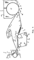
- the forming section 5 may be a so-called C-former, as shown in Figures 1 , 2 , 7 and 8 , or a so-called Crescent former, as shown in Figures 3-6 , or a so-called suction breast roll former, as shown in Figures 9 and 10 .
- the main press 11 is a long nip press, e.g. a shoe press, in which the first press element 12 is a smooth counter roll and the second press element 13 comprises a press shoe and an endless belt or a jacket running through the press nip of the shoe press in sliding contact with the press shoe, which exerts a predetermined pressure on the inside of the belt and on the counter roll 12.
- the press shoe thus constitutes a device forming an extended press nip.
- the first press element 12 is a smooth counter roll and the second press element comprises a device for forming an extended press nip, said device including an elastic support body arranged to press in the direction towards the counter roll.
- the press element 13 is a smooth counter roll, while the second press element 12 comprises a device forming an extended nip of any one of the types known in paper making.
- the press felt 17 of the main press is also used as the first inner forming clothing 8 of the forming section 5 so that the forming roll 7 is also located within the loop of the press felt 17.
- the wet section 2 in this case also comprises a predewatering device 24, namely a suction device.
- the device 24 comprises a suction roll 25 located within the loop of the press felt 17, and a steam box 26 located on the outside of the loop of the press felt 17 in front of the suction roll 25 for heating the water in the fibrous network of the formed fibrous web 1'.
- a high-pressure spray device 55 that is a needle-type spray device with a jet diameter of 1 mm, is arranged on the outside of the forming felt 8 upstream of the forming roll 7 in order to clean the forming felt 8 before it reaches the forming roll 7.
- the embodiment according to Figure 2 is similar to that of Figure 1 , except that it is additionally provided with a preheating device 27 downstream of the main press 11 in order to increase the temperature of the structured fibrous web 1" in the press 11 before the fibrous web 1" reaches the drying cylinder 19.
- the structuring belt 14 is also used as the first inner forming clothing 8 of the forming section so that the forming roll 7 is also located within and surrounded by the loop of the structuring belt 14.
- the press felt 17 of the main press 11 runs in a single loop about a plurality of guide rolls 28 and the second press element 13.
- the guide roll located upstream of the second press element 13 is a suction roll 29 by means of which water is removed from the press felt 17 in order to increase the capacity of the press felt 17 to dispose of relatively large quantities of water pressed out in the nip N1.
- One special effect with this embodiment, in which the structuring belt 14 also passes about the forming roll 7, is that it will be possible for the fibres of the stock to penetrate into and orient themselves in the z-direction in the depressions of the structuring belt 14 so that some of the formed fibrous web 1' is already oriented in the depressions before pressing is started in the main press 11. Such a pre-orientation of fibres in the depressions is therefore advantageous in order to provide higher bulk.
- a spray device 53 is arranged on the inside of the press felt 17 for supplying fresh water into the wedge-shaped tapering space between the press felt 17 and the guide roll 28, said water being pressed into the press felt 17 and displaces the contaminated water in the press felt 17 after pressing in the main press 11 through and out of the press felt 17 when this runs about the guide roll 28.
- suction boxes 54 are arranged on the outside of the press felt 17 in order to withdraw water out from the press felt 17, as well as a high-pressure spray device 55 which cleans the press felt 17 before it arrives at the suction roll 29, which deals with the remaining water in the press felt 17.
- the suction roll 29 removes water from the press felt 17 and thus increases the capacity of the press felt to absorb the water in the nip N1.
- the embodiment according to Figure 4 is similar to that of Figure 3 , except that it is additionally provided with a preheating device 27 corresponding to the embodiment according to Figure 2 and that a steam box 31 is arranged on the outside of the press felt 17 immediately in front of the suction roll 29 in order to increase the dewatering capacity thereof.
- the first inner forming clothing 8, the press felt 17 and the structuring belt 14 have their own loops, wherein the forming clothing 8 is a felt running about a plurality of guide rolls 18'.
- the press section 3 in this case comprises a pre-press 32 including a first press element 33 located within the loop of the press felt 17 and a second press element 34 located within the first inner forming clothing 8, said press elements 33, 34 forming a press nip N3 with each other through which the forming felt 8 carrying the fibrous web 1' runs in order to meet the press felt 17 which also runs through the said press nip N3 in order to receive the formed fibrous web 1' and carry it on to the main press 11.
- the forming felt 8 thus also forms the second press felt of the pre-press 32.
- the guide roll located immediately upstream of the second press element 34 is a suction roll 35 by means of which water is removed from the forming felt 8.
- a steam box 36 is located on the outside of the forming felt 8 immediately in front of the suction roll 35 in order to make the dewatering of the felt 8 more effective.
- a spray device 53' is arranged on the inside of the forming felt 8 for supplying fresh water into the wedge-shaped tapering space between the forming felt 8 and the guide roll 18', said water being pressed into the forming felt 8 and displaces the contaminated water in the forming felt 8 after pressing in the pre-press 32 through and out of the forming felt 8 when this runs about the guide roll 18'.
- suction boxes 54' are arranged on the outside of the forming felt 8 in order to withdraw water out from the press felt 8, as well as a high-pressure spray device 55' which cleans the forming felt 8 before it reaches the forming roll 7.
- the embodiment according to Figure 6 is similar to that of Figure 5 , except that it is additionally provided with a preheating device 27 corresponding to the embodiment according to Figure 2 .
- the first inner forming clothing 8, that is a forming fabric, the press felt 17 and the structuring belt 14 have their own loops as in the embodiment according to Figure 5 .
- the forming section 5 is thus a twin-wire C-former.
- the forming roll 7 may be a suction roll if desired.
- the press section 3 in this case also comprises a pre-press 32 including a first press element 33 located within the loop of the press felt 17 and a second press element 34 located within a second press felt 37 running in a loop about a plurality of guide rolls 38, wherein the guide roll located immediately upstream of the second press element 34 is a suction roll 39 by means of which water is removed from the second press felt 37.
- a steam box 50 is located on the outside of the second press felt 37 immediately in front of the suction roll 39 in order to improve dewatering of the press felt 37.
- the second press felt 37 runs in contact with the first inner forming fabric 8 in order to form a transfer zone in which the press felt 37, the formed fibrous web 1' and the forming fabric 8 form a sandwich structure.
- a suction device 51 may be located within the loop of the second press felt 37 after the transfer zone in order to ensure the transfer of the fibrous web 1'.
- a spray device 53' is arranged on the inside of the press felt 37 for supplying fresh water into the wedge-shaped tapering space between the press felt 37 and the guide roll 38, said water being pressed into the press felt 37 and displaces the contaminated water in the press felt 37 after pressing in the pre-press 32 through and out of the press felt 37 when this runs about the guide roll 38.
- suction boxes 54' are arranged on the outside of the press felt 37 in order to withdraw water out from the press felt 37, as well as a high-pressure spray device 55' which cleans the press felt 37 before it reaches the suction device 51.
- the embodiment according to Figure 8 is similar to that of Figure 7 , except that it is additionally provided with a preheating device 27 after the main press corresponding to the embodiment according to Figure 2 in order to increase the temperature and dryness of the paper web 1".
- the embodiment according to Figure 9 is similar to that of Figure 7 except for the wet section 2 which in this case has a forming section of a type other than C-former and Crescent former as mentioned previously.
- the forming section according to Figure 9 is a so-called suction breast roll former including a headbox 6, a forming roll 7, that is a suction breast roll, and a forming clothing 8, that is a forming fabric, running in a loop about the suction breast roll 7 and guide rolls 18 and forming a transfer zone with the second press felt 37 corresponding to the embodiment according to Figure 7 .
- the suction breast roll 7 has a suction zone 52 forming a forming zone across which the forming fabric 8 passes together with stock emitted in a jet from the headbox 6 and dewatered within the forming zone 52 in order to form a formed fibrous web 1'.
- the embodiment according to Figure 10 is similar to that of Figure 9 , except that it is additionally provided with a preheating device 27 corresponding to the embodiment according to Figure 2 .
- the pre-press 32 used in the embodiments according to Figures 5-10 may be a press selected from the group of different presses described above in connection with the main press 11.
- the structuring belt 14 comprises a structuring layer 60 forming the side of the structuring belt carrying the paper web.
- the layer 60 has a web-contacting surface 61 with a three-dimensional structure formed by the depressions 63 in the form of recesses or pockets in the otherwise flat web-contacting surface 61, said depressions 63 being regularly recurrent and distributed in the longitudinal direction (MD) and cross direction (CD) of the structuring belt.
- the web-contacting surface 61 thus has a flat, continuous top surface area 70 in which said depressions 63 are formed. Each depression 63 in the web-contacting surface 61 is thus delimited by said continuous surface area 70.
- further patterns in the form of figures or text may be formed in the structuring layer 60.
- All of the depressions 63 are preferably identical and are arranged in a regular pattern.
- one and the same structuring belt may comprise two or more groups of depressions, wherein the design of the depressions in the different groups differs, but the depressions within each group are identical.
- the structuring belt 14 allows the wet fibrous web 1' to be formed into the depressions 63 when the fibrous web 1' passes through the press nip N1 together with the press felt 17 and the structuring belt 14 with the wet fibrous web 1' enclosed therebetween. It is also important that the press felt 17 can reach down into all of the depressions 63 during the pressing process in order to build up a sufficiently high hydraulic pressure so that water in the wet fibrous web 1' can move into the press felt 17 and not remain in the fibrous web at the end of the pressing operation.
- the depressions 63 must be sufficiently large to allow the press felt 17 to penetrate into the depressions 63.
- Each depression 63 must have an optimum depth which allows water in the bottom of the depression 63 to be transported away. In other words, the depth of the depression 63 must not be too great, as an excessive depth will prevent the desired hydraulic pressure from building up.
- the structuring layer 60 with this specific well-defined, structured, web-contacting surface 61 is an important parameter for controlling the structure, thickness/bulk and dryness that can be expected in the structured and dewatered fibrous web 1" after the press nip N1 before final drying. It is taken for granted that the pressure in the press nip N1 is within the normal ranges conventionally used for pressing, normally a maximum of 6 MPa, and that the press felt 17 is of the conventional elastically compressible type, which, in addition to its required water-receiving capacity during compression, forms elastically into the web-contacting surface of the structuring layer with the wet fibrous web located therebetween in the manner and for the purpose specified above.
- Each depression 63 has a predetermined dimension l in the machine direction (MD) of the structuring layer 60 and a predetermined dimension b in the cross direction (CD) of the belt 14.
- the depressions 63 may be oriented in the machine direction, in which case l > b , or in the cross direction, in which case l ⁇ b .
- the depressions 63 are preferably oriented substantially in the machine direction, as this gives better creping and results in a softer tissue paper. It should be noted here that woven structuring clothings normally have a pattern that is MD-oriented.
- Each depression 63 also has a predetermined depth d , a predetermined area a and a predetermined volume v .
- the depth d of the depressions may be constant over substantially all of the depression 63, in which case the depression 63 has a bottom surface 71 which is flat and parallel to the surface area 70.
- the depth d may alternatively vary over the surface of the depression 63 and then an average depth or mean depth d is preferably used to characterise the extension of the depression 63 in the z-direction.
- the depressions 63 are arranged at a predetermined distance from each other so that they are distributed in a uniform manner over the web-contacting surface 61 and cover a predetermined part thereof.
- the abovementioned continuous top surface area 70 which delimits the depressions 63 and constitutes the part of the web-contacting surface 61 cooperating with the drying surface 20 when the fibrous web 1" is transferred to the drying cylinder 19, constitutes the remaining part of the web-contacting surface 61.
- a should be measured in the plane of the top surface area 70. However, tests have shown that a should preferably be within the range of 0.5-2.0 mm 2 .
- the structuring belt 14 is compressed when it passes through the nip N1 between the press elements 12 and 13.
- the abovementioned range for d applies when the structuring belt 14 and therefore also the depressions 63 are in the compressed state, i.e. when the structuring belt 14 is passing through the nip N1.
- the press pressure in this nip has normally a maximum of 6 MPa.
- the structuring belt 14 is in the compressed state, this refers to the fact that it is loaded with a pressure of a maximum of 6 MPa.
- the depressions 63 in the non-compressed state can consequently have a depth d greater than 0.6 mm, but in the compressed state, i.e.
- d should not exceed 0.6 mm.
- the value d refers to the mean depth of the depression.
- the greatest depth of the depression exceed 0.6 mm when the depression is in the compressed state.
- the depressions should altogether cover between 20 % and 80 % of the total web-contacting surface 61.
- a creped, reeled tissue paper having the following properties can be manufactured in a tissue papermaking machine provided with a structuring belt with a structuring layer as above: Basis weight 10-50 g/m 2 Thickness 160-400 ⁇ m, preferably 200-300 ⁇ m Bulk 8-20 cm 3 /g MD tensile strength 50-300 N/m CD tensile strength 30-250 N/m and Softness 70-90
- the above values refer to a paper conditioned at 20°C and 50 % atmospheric humidity.
- the softness value is measured according to EMTEC TSA (Tissue Softness Analyzer) with a measuring scale from 0 to 100.
- the above bulk and softness values should be compared with those for conventional creped tissue paper, which has a bulk in the range of 5-9 cm 3 /g and a softness in the range of 50-70.
- tissue paper of the qualities facial i.e. facial tissues, toilet paper and household paper
- said tissue paper having the following properties: Facial Toilet paper Household paper Basis weight [g/m 2 ] 13-15 15-25 18-23 Bulk [cm 3 /g] 10-13 10-15 10-14 MD tensile strength [N/m] 70-120 50-150 170-300 CD tensile strength [N/m] 50-100 30-100 170-300
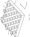
- Figure 11 shows a first embodiment of a structuring belt 14 with a structuring layer 60 according to the invention, said structuring layer 60 including reinforcing means 57 and being arranged on a wear layer 58.
- Figure 12 is a partial view of this belt 14 in a cross section in the machine direction (MD).
- the web-contacting surface 61 of the structuring layer 60 has a plurality of identical depressions 63 in the form of recesses or pockets, arranged in parallel rows 72, extending in the machine direction of the belt 14. Adjacent rows 72 are displaced by approximately half the length of a pocket relative to each other in the machine direction.
- Each depression 63 is substantially in the form of a square block with cylindrical ends, said square block extending in the machine direction of the belt 14.
- each depression 63 is flat and parallel to the continuous top surface area 70.
- the side walls 73 of the depression 63 form a substantially 90° angle relative to the bottom surface 71 of the pocket.
- the depressions 63 have a dimension l in the machine direction of 2.0 mm and a dimension b in the cross direction of 1.0 mm.
- the depth d is 0.3 mm.
- the depressions 63 have an area a in the range of 0.3-4.0 mm 2 , and preferably 0.5-2.0 mm 2 , e.g. approximately 1.8 mm 2 , and a volume v of 0.05-1.0 mm 3 , preferably approximately 0.54 mm 3 .
- the distance between two adjacent depressions 63 in the machine direction s is approximately 1.0 mm.
- the distance between two adjacent rows 72 of depressions 63 in the cross direction t is approximately 0.5 mm.
- the depressions 63 cover approximately 40 % of the web-contacting surface 61.
- Figure 13 shows a second embodiment of a structuring layer 60 of a structuring belt 14 according to the invention.
- the structuring layer 60 of the belt 14 has depressions 63 of substantially the same form and arranged in the same manner as the depressions described above.
- the depressions 63 have a dimension l in the machine direction of 1.0 mm, a dimension b in the cross direction of 0.5 mm, a depth d of 0.2 mm, an area a of approximately 0.3-4.0 mm 2 , e.g. 0.45 mm 2 , and a volume v of approximately 0.09 mm 3 .
- the distance between two adjacent depressions 63 in the machine direction s is 0.5 mm.
- the distance between two adjacent rows 72 of depressions 63 in the cross direction t is 0.5 mm.
- Figure 14 shows a third embodiment of a structuring layer according to the invention, said structuring layer also having the depressions 63 of substantially the same form and arranged in the same manner as the depressions described in connection with Figure 11 .
- the depressions 63 are slightly larger than the depressions shown in Figure 13 and have a dimension l in the machine direction of 0.5 mm, a dimension b in the cross direction of 1.0 mm, a depth d of 0.4 mm, an area of approximately 1.3 mm 2 and a volume v of approximately 0.51 mm 3 .
- the distance between two adjacent depressions 63 in the machine direction s is 0.5 mm.
- the distance between two adjacent rows 72 of depressions 63 in the cross direction t is 0.5 mm.
- Figure 15 shows a further embodiment of a structuring layer according to the invention.
- the depressions 63 are formed by recesses or pockets, which, except for rounded inner corners, are substantially entirely rectangular or formed as square blocks.
- the depressions 63 are arranged in rows 72 extending in the machine direction of the belt 14 and columns 74 extending in the cross direction of the belt 14.
- the depressions 63 have a dimension l in the machine direction of 2.0 mm, an extent b in the cross direction of 2.0 mm, a depth d of 0.2 mm, an area of approximately 3.9 mm 2 and a volume v of approximately 0.79 mm 3 .
- the distance between two adjacent depressions 63 in the machine direction s is 1.0 mm.
- the distance between two adjacent rows 72 of depressions 63 in the cross direction t is 1.0 mm.
- Figure 16 shows an alternative embodiment of a structuring layer according to the invention, in which the structuring layer instead of recesses is provided with elevations 62 in the form of projecting portions or "islands" in the otherwise flat, continuous lower surface area 76.
- the same parameter values specified above in the case of the structuring layer with recesses also apply to this variant of the structuring layer, with the difference that the value d in this case gives the height of the elevations.
- the elevations 62 are in the form of square blocks projecting approximately 0.2 mm from the lower surface area 76 and having slightly rounded outer corners.
- the square blocks are approximately 1 mm long and 1 mm wide and are arranged in rows extending diagonally in the machine direction of the structuring belt 14.
- the elevations consequently have a dimension l in the machine direction and a dimension b in the cross direction of approximately 1.4 mm in each case.
- Each elevation 62 has an area a of approximately 0.95 mm 2 and a volume v of approximately 0.19 mm 3 .
- the distance between adjacent elevations is approximately 0.5 mm and the elevations 62 consequently cover approximately 42 % of the web-contacting surface 61.
- the upper surface areas 75 of the elevations 62 are preferably flat so that they cooperate with the drying surface 20 when the fibrous web 1" is transferred to the drying cylinder 19.
- the structuring layer according to the invention is preferably made of a polymer material, e.g. polyurethane, the depressions 63 or the lower surface area 76 preferably being formed in said structuring layer in that material is cut from the surface of the structuring layer.
- the structuring layer 60 may alternatively be made of a different material, e.g. metal or carbon fibre, and other techniques may be used to form the depressions or said lower surface area.
- the structuring layer 60 is preferably approximately 3-6 mm thick, but its thickness may be between 0.2 and 10 mm.
- the structuring belt is preferably substantially water-impermeable as mentioned for the tissue papermaking machines shown.
- the structuring belt may be water-permeable.
- the structuring layer may be needled so that it has through holes.
- the depressions 63 or the surface area 70 surrounding the depressions, or both, may be needled.
- the elevations 62 and/or said lower surface area 76 may be needled.
- the structuring belt 14 may comprise a wear layer 58, e.g. in the form of a felt layer arranged on the side of the structuring belt 14 directed away from the fibrous web 1'.
- the wear layer 58 may be needled.
- the structuring belt 14 may comprise reinforcing means 57, e.g. in the form of reinforcement wires arranged within the structuring layer 60.
- the reinforcing means may alternatively be formed by a metal strip or a fabric arranged within the structuring layer 60.
- tissue paper web which, after creping from the drying surface 20 and conditioning at 20°C and an air humidity of 50 %, has a basis weight in the range of 10-50 g/m 2 , a thickness in the range of 160-400 ⁇ m, preferably 200-300 ⁇ m, a bulk in the range of 8-20 cm 3 /g, an MD tensile strength in the range of 50-300 N/m, a CD tensile strength in the range of 30-250 N/m and a softness in the range of 70-90 as measured according to EMTEC TSA (Tissue Softness Analyzer) with a measuring scale of 0 to 100.
- EMTEC TSA tissue Softness Analyzer
- FIG 17 is a cross section through a tissue paper web 1 manufactured by a structuring belt including depressions according to the invention.
- the finished tissue paper web 1 has a varying thickness, wherein the thickness of the tissue paper web 1 is greater in those portions 77 in which the tissue paper web 1 has been formed by the top surface area 70 than in those portions 78 in which the tissue paper web 1 has been formed by the depressions 63 of the structuring belt 14.
- the fibrous web 1', 1" preferably comprises a short-fibre layer and a long-fibre layer, wherein the fibrous web 1', 1" is transferred to the drying surface 20 in the transfer nip N2 with the short-fibre layer directed towards the drying surface 20.
- the finished tissue paper web 1 thus preferably also has a short-fibre layer on one side 79, i.e. the side which has been in contact with the drying surface 20, and a long-fibre layer on its other side 80, i.e. on the side which has been in contact with the structuring belt 14.
- Figure 18 shows the long-fibre side 80 of the tissue fibre web 1.
Claims (38)
- Strukturierungsriemen (14), umfassend eine Strukturierungsschicht (60), die ausgelegt ist, um eine nasse Faserbahn (T) während des Durchgangs in einem erweiterten Druckspalt (N1) in einem Pressabschnitt (3) einer Tissuepapierherstellungsmaschine zur Herstellung eines Tissuepapiers (1"') mit hohem Volumen zu strukturieren, wobei die Strukturierungsschicht (60) nicht gewoben ist und eine Bahn-tragende Seite mit einer Oberfläche (61) zur Zusammenarbeit mit der Faserbahn (1') aufweist, wobei die Oberfläche (61) eines von Vertiefungen (63) und Erhöhungen (62) aufweist, die eine dreidimensionale Struktur der Oberfläche (61) bilden, wobei die eine von Vertiefungen (63) und Erhöhungen (62) über die Bahn-tragende Seite verteilt sind und zusammen 20 - 80 der Oberfläche (61) ausmachen, wobei die Oberfläche (61), wenn sie Vertiefungen (63) umfasst, einen flachen oberen Oberflächenbereich (70) zwischen den Vertiefungen (63) einschließt, wobei der obere Oberflächenbereich (70) die Vertiefungen (63) begrenzt, und die Oberfläche (61), wenn sie Erhöhungen (62) umfasst, einen flachen Taloberflächenbereich (76) zwischen den Erhöhungen (62) einschließt, wobei der Taloberflächenbereich (76) die Erhöhungen (62) begrenzt, und wobei jede Vertiefung (63) oder Erhöhung (62) jeweils eine Abmessungl von 0,25 - 2,5 mm in einer ersten Richtung in der Ebene des oberen Oberflächenbereichs (70) bzw. des Taloberflächenbereichs (76), eine Abmessung b von 0,25 - 2,0 mm in einer zweiten Richtung in der Ebene des oberen Oberflächenbereichs (70) bzw. des Talflächenbereichs (76), wobei die erste und die zweite Richtung in rechten Winkeln zueinander liegen, eine mittlere Tiefe bzw. eine mittlere Höhe d von 0,05 - 0,6 mm, wenn sich die Strukturierungsschicht (60) in einem komprimierten Zustand befindet, wenn der Strukturierungsriemen mit einem Druck von 6 Mpa geladen ist, und einen Bereich a, wie gemessen in der Ebene des oberen Oberflächenbereichs (70) bzw des Taloberflächenbereichs (76), von 0,3 - 4,0 mm2 aufweist.
- Strukturierungsriemen (14) nach Anspruch 1, dadurch gekennzeichnet, dass der obere Oberflächenbereich (70) bzw. der Taloberflächenbereich (76) kontinuierlich ist.
- Strukturierungsriemen (14) nach Anspruch 2, dadurch gekennzeichnet, dass jede Vertiefung (63) bzw. Erhöhung (62) einen Bereich a aufweist, wie gemessen in der Ebene des oberen Oberflächenbereichs (70) bzw. des Taloberflächenbereichs (76), von 0,5 - 2,0 mm2.
- Strukturierungsriemen (14) nach einem der Ansprüche 2 und 3, dadurch gekennzeichnet, dass jede Vertiefung (63) bzw. Erhöhung (62) einen Inhalt v von 0,05 - 1,0 mm3 aufweist.
- Strukturierungsriemen (14) nach einem der Ansprüche 2 - 4, dadurch gekennzeichnet, dass alle der Vertiefungen (63) bzw. Erhöhungen (62) in der Oberfläche (61) identisch sind.
- Strukturierungsriemen (14) nach einem der Ansprüche 2 - 5, dadurch gekennzeichnet, dass die Vertiefungen (63) bzw. Erhöhungen (62) in einem regelmäßigen Muster angeordnet sind.
- Strukturierungsriemen (14) nach einem der Ansprüche 2 - 4,dadurch gekennzeichnet, dass die Vertiefungen in zwei oder mehrere Gruppen von Vertiefungen (63) gruppiert sind, wobei die Vertiefungen (63) in den verschiedenen Gruppen verschieden sind, aber wobei die Vertiefungen (63) innerhalb jeder Gruppe identisch sind.
- Strukturierungsriemen (14) nach einem der Ansprüche 2 - 6, dadurch gekennzeichnet, dass die Vertiefungen (63) bzw. Erhöhungen (62) in parallelen Reihen angeordnet sind, die sich in der Maschinenrichtung (MD) der Strukturierungsschicht (60) erstrecken.
- Strukturierungsriemen (14) nach einem der Ansprüche 2 - 6 und 8, dadurch gekennzeichnet, dass sich die Abmessung jeder Vertiefung (63) bzw. Erhöhung (62) in der Maschinenrichtung (MD) der Strukturierungsschicht (60) erstreckt, dass sich die Abmessung b jeder Vertiefung (63) bzw. Erhöhung (62) in der Querrichtung (CD) der Strukturierungsschicht (60) erstreckt, und dass l > b.
- Strukturierungsriemen (14) nach einem der Ansprüche 2 - 9, dadurch gekennzeichnet, dass die Strukturierungsschicht (60) aus einem der Materialien Polyurethan, Kohlenstoff, Kohlenstofffaser und Metall hergestellt ist.
- Strukturierungsriemen (14) nach einem der Ansprüche 1 - 10, dadurch gekennzeichnet, dass er eine Abnutzungsschicht (58) umfasst, die auf der Seite des Strukturierungsriemens (14) angeordnet ist, die weg von der Faserbahn (1') gerichtet werden soll.
- Strukturierungsriemen (14) nach Anspruch 11, dadurch gekennzeichnet, dass er Verstärkungsmittel (57) umfasst.
- Strukturierungsriemen (14) nach einem der Ansprüche 1 - 12, dadurch gekennzeichnet, dass er wasserdurchlässig ist.
- Strukturierungsriemen (14) nach einem der Ansprüche 1 - 12, dadurch gekennzeichnet, dass er wasserundurchlässig ist.
- Pressabschnitt (3) für eine Tissuepapierherstellungsmaschine, wobei der Pressabschnitt (3) Folgendes umfasst:- eine Hauptpresse (11), einschließend:wobei das erste Presselement (12) innerhalb der Schleife des zweiten Gewebes (14) angeordnet ist, und- ein erstes Presselement (12),- ein zweites Presselement (13), wobei die Presselemente (12, 13) einen erweiterten Druckspalt (NI) zwischen sich mit einem vorbestimmten Druck bilden,- ein erstes Gewebe in Form eines elastischen, komprimierbaren Filzes (17), das in einer Endlosschleife um eine Vielzahl von Führungswalzen (18) und durch den Druckspalt (NI) zusammen und in Kontakt mit der gebildeten Faserbahn (1') verläuft, wobei das zweite Presselement (13) innerhalb der Schleife des Pressfilzes (17) angeordnet ist,- eine zweites Gewebe (14), das in einer Endlosschleife um eine Vielzahl von Führungswalzen (15) und durch den Druckspalt (NI) zusammen und in Kontakt mit der gebildeten Faserbahn (1') verläuft,- eine Übertragungswalze (16) zum Bilden eines Übertragungsdruckspalts (N2) gegen eine Trockenoberfläche (20) eines Trockenabschnitts (4) nach dem Pressabschnitt (3), wobei die Übertragungswalze (16) innerhalb der Schleife des zweiten Gewebes (14) angeordnet ist,dadurch gekennzeichnet, dass das zweite Gewebe (14) ein Strukturierungsriemen mit einer Strukturierungsschicht (60) gemäß einem der Ansprüche 1 - 10 zum Bilden einer strukturierten Faserbahn (1 ") mit hohem Volumen ist.
- Pressabschnitt (3) nach Anspruch 15, dadurch gekennzeichnet, dass eines der Presselemente (12, 13) eine Schuhpresswalze umfasst.
- Pressabschnitt (3) nach Anspruch 15, dadurch gekennzeichnet, dass eines der Presselemente (12, 13) einen elastischen Trägerkörper umfasst, der angeordnet ist, um in der Richtung hin zu dem anderen der Presselemente (12, 13) zu pressen, die in Form einer glatten Gegenwalze bereitgestellt sind.
- Tissuepapierherstellungsmaschine zum Herstellen einer strukturierten Tissuepapierbahn (1) mit hohem Volumen mit Hilfe von Pressen, umfassend:- einen nassen Abschnitt (2) zum Bilden einer Faserbahn (1'),- einen Trockenabschnitt (4) zum endgültigen Trockenen der Faserbahn (1"), wobei der Trockenabschnitt (4) Folgendes umfasst:dadurch gekennzeichnet, dass die Tissuepapierherstellungsmaschine einen Pressabschnitt (3) nach einem der Ansprüche 15 - 17 umfasst, der zwischen dem nassen Abschnitt (2) und dem Tockenabschnitt (4) angeordnet ist, wobei die Übertragungswalze (16) des Pressabschnitts (3) einen Übertragungsspalt (N2) zusammen mit der Trockenoberfläche (20) bildet, um die Faserbahn (1") auf die Trockenoberfläche (20) zu übertragen, ohne die Faserbahn (1") im Übertragungsdruckspalt (N2) zu entwässern.- eine Trockenoberfläche (20) zum Trocknen der Faserbahn (1 "), und- eine Kreppführung (21) zum Kreppen der Bahn von der Trockenoberfläche (20), so dass eine gekreppte Tissuepapierbahn (1) von der Trockenoberfläche (20) entfernt werden kann,
- Tissuepapierherstellungsmaschine nach Anspruch 18, dadurch gekennzeichnet, dass der nasse Abschnitt (2) einen Stoffauflaufkasten (6) umfasst, eine Formwalze (7), ein erstes Formgewebe (8), das um die und in Kontakt mit der Formwalze verläuft, und eine Entwässerungsvorrichtung (24).
- Tissuepapierherstellungsmaschine nach Anspruch 19, dadurch gekennzeichnet, dass die Entwässerungsvorrichtung (24) eine Saugwalze (25) umfasst, die in der Schleife des ersten Formgewebes (8) nachgelagert von der Formwalze (7) angeordnet ist, und einen Dampfkasten (26), der auf der Außenseite der Schleife des ersten Formgewebes (8) vor der Saugwalze (25) angeordnet ist.
- Tissuepapierherstellungsmaschine nach einem der Ansprüche 18 - 20, dadurch gekennzeichnet, dass die Trockenoberfläche (20) durch die Mantelfläche eines Trockenzylinders (19) gebildet ist.
- Tissuepapierherstellungsmaschine nach Anspruch 21, dadurch gekennzeichnet, dass der Trockenzylinder (19) ein Yankee-Zylinder ist.
- Tissuepapierherstellungsmaschine nach einem der Ansprüche 18 - 20, dadurch gekennzeichnet, dass die Trockenoberfläche (20) durch einen Metallriemen gebildet ist.
- Tissuepapierherstellungsmaschine nach einem der Ansprüche 18 - 23, dadurch gekennzeichnet, dass der Pressabschnitt (3) auch eine Vorpresse (32) umfasst, darin eingeschlossen ein erstes Presselement (33) und ein zweites Presselement (34), wobei die Presselemente (33, 34) einen Druckspalt (N3) zwischen sich bilden, einen Pressfilz (8, 37), der in einer Endlosschleife um eine Vielzahl von Führungswalzen (18; 38) und durch den Druckspalt zusammen mit dem Pressfilz (17) der Hauptpresse (11) verläuft,
wobei das zweite Presselement (34) innerhalb der Schleife des Pressfilzes (8; 37) der Vorpresse (32) angeordnet ist, und das erste Presselement (33) innerhalb der Schleife des Pressfilzes (17) der Hauptpresse angeordnet ist, und wobei die gebildete Faserbahn (1') durch den Druckspalt der Vorpresse verläuft, der zwischen zwei Pressfilzen (17, 8; 17, 37) eingeschlossen ist. - Tissuepapierherstellungsmaschine nach Anspruch 24, dadurch gekennzeichnet, dass sich die Schleife des Strukturierungsriemens (14) zwischen der Hauptpresse (11) und der Übertragungswalze (16) erstreckt, und dass sich die Schleife des Pressfilzes (17) der Hauptpresse (11) zwischen der Formwalze (7) und der Hauptpresse (11) erstreckt, wobei der Pressfilz (17) der Hauptpresse (11) auch das erste Formgewebe (8) bildet.
- Tissuepapierherstellungsmaschine nach Anspruch 24, dadurch gekennzeichnet, dass sich die Schleife des Strukturierungsriemens (14) zwischen der Formwalze (7) und der Übertragungswalze (16) erstreckt, um auch das erste Formgewebe (8) zu bilden.
- Tissuepapierherstellungsmaschine nach Anspruch 24, dadurch gekennzeichnet, dass sich der Strukturierungsriemen (14) zwischen der Hauptpresse (11) und der Übertragungswalze (16) erstreckt, dass sich der Pressfilz (17) der Hauptpresse zwischen der Vorpresse (32) und der Hauptpresse (11) erstreckt, und dass sich das erste Formgewebe (8) zwischen der Formwalze (7) und der Vorpresse (32) erstreckt, und den Pressfilz der Vorpresse (32) bildet.
- Tissuepapierherstellungsmaschine nach Anspruch 24, dadurch gekennzeichnet, dass sich der Strukturierungsriemen (14) zwischen der Hauptpresse (11) und der Übertragungswalze (16) erstreckt, dass sich der Pressfilz (17) der Hauptpresse zwischen der Vorpresse (32) und der Hauptpresse (11) erstreckt, dass sich der Pressfilz der Vorpresse (32) zwischen einem Übertragungsbereich und der Vorpresse (32) erstreckt, und dass sich die Schleife des Formgewebes (8) zwischen der Formwalze (7) und der Führungswalze (32) erstreckt, die in Verbindung mit dem Übertragungsbereich angeordnet ist.
- Tissuepapierherstellungsmaschine nach einem der Ansprüche 18 - 28, dadurch gekennzeichnet, dass das zweite Presselement (13) der Hauptpresse eine Vorrichtung zum Bilden des erweiterten Druckspalts zur Zusammenarbeit mit dem ersten Presselement (12) umfasst.
- Tissuepapierherstellungsmaschine nach Anspruch 29, dadurch gekennzeichnet, dass die Hauptpresse (11) eine Schuhpresse ist, und dass die Vorrichtung zum Bilden des erweiterten Druckspalts einen Pressschuh und einen Endlosriemen umfasst, der durch den erweiterten Druckspalt verläuft, wobei der Pressschuh entworfen ist, um gegen die Innenseite des Riemens zu pressen.
- Verfahren zum Herstellen einer strukturierten Tissuepapierbahn (1) mit hohem Volumen in einer Tissuepapierherstellungsmaschine nach einem der Ansprüche 18 - 30, wobei das Verfahren Folgendes umfasst:- Bilden einer Faserbahn (1') im nassen Abschnitt (2),- Entwässern und Strukturieren der gebildeten Faserbahn (1') mit Hilfe von Pressen im Pressabschnitt (3), so dass die Faserbahn (1') durch die Strukturierungsschicht (60) strukturiert wird, und- endgültiges Trocknen der entwässerten und strukturierten Faserbahn (1 ") im Trockenabschnitt (4),wobei die Faserbahn (1 ") durch den Strukturierungsriemen (14) vom Druckspalt (N1) der Hauptpresse (11) zum Übertragungsdruckspalt (N2) der Übertragungswalze (16) gegen die Trockenoberfläche (20) getragen wird.
- Verfahren nach Anspruch 31, dadurch gekennzeichnet, dass die Faserbahn (1', 1 ") von einer Trockenheit im Bereich von 15 - 30 % auf eine Trockenheit im Bereich von 42 - 52 % gebracht wird, wenn sie durch den Pressabschnitt (3) verläuft.
- Verfahren nach Anspruch 31 oder 32, dadurch gekennzeichnet, dass die Faserbahn (1', 1 ") eine Kurzfaserschicht und eine Langfaserschicht umfasst, und dass die Faserbahn (1', 1 ") an die Trockenoberfläche (20) im Übertragungsdruckspalt (N2) übertragen wird, wobei die Kurzfaserschicht hin zur Trockenoberfläche (20) gerichtet ist.
- Verfahren zum Umwandeln einer Tissuepapierherstellungsmaschine, darin eingeschlossen einen Pressabschnitt gemäß dem Oberbegriff von Anspruch 15, wobei das zweite Gewebe des Pressabschnitts durch einen Strukturierungsriemen (14) ersetzt ist, der eine Strukturierungsschicht (60) gemäß einem der Ansprüche 1 - 10 umfasst, wodurch eine Tissuepapierherstellungsmaschine zum Herstellen einer weichen Tissuebahn mit hohem Volumen erhalten wird.
- Verwendung eines Pressabschnitts nach Anspruch 15 - 17 zur Herstellung einer Tissuefaserbahn (1 ").
- Tissuepapierbahn (1), hergestellt in einer Tissuepapierherstellungsmaschine nach einem der Ansprüche 18 - 30, wobei sie, nach dem Kreppen von der Trockenoberfläche (20) und dem Konditionieren bei 20 ºC und einer Luftfeuchtigkeit von 50 % ein Grundgewicht im Bereich von 10 - 50 g/m2, eine Dicke im Bereich von 160 - 400 µm, ein Volumen im Bereich von 8 - 20 cm3/g, eine MD-Zugfestigkeit im Bereich von 50 - 300 N/m, eine CD-Zugfestigkeit im Bereich von 50 - 250 N/m, und eine Weichheit im Bereich von 70 - 90, wie gemessen gemäß EMTEC TSA (Gewebeweichheitsanalysator) mit einer Messskala von 0 - 100 umfasst.
- Tissuepapierbahn (1) nach Anspruch 36, dadurch gekennzeichnet, dass die eine variable Dicke aufweist.
- Tissuepapierbahn (1) nach Anspruch 37, dadurch gekennzeichnet, dass die Dicke der Tissuepapierbahn (1) größer in denjenigen Abschnitten, in denen die Tissuepapierbahn (1) durch die oberen Oberflächenbereiche (70) gebildet wurde, als in denjenigen Abschnitten ist, in denen die Tissuepapierbahn (1) durch die Vertiefungen (63) des Strukturierungsriemens (14) der Tissuepapierherstellungsmaschine gebildet wurde.
Applications Claiming Priority (4)
| Application Number | Priority Date | Filing Date | Title |
|---|---|---|---|
| SE0702543A SE531891C2 (sv) | 2007-11-20 | 2007-11-20 | Struktureringsbeklädnad och förfarande för framställning av en tissuepappersbana |
| US9783708P | 2008-09-17 | 2008-09-17 | |
| SE0801991A SE532839C2 (sv) | 2007-11-20 | 2008-09-17 | Struktureringsband, pressparti och tissuepappersmaskin för framställning av en högbulkkräppad tissuepapersbana och förfarande därför |
| PCT/SE2008/051332 WO2009067079A1 (en) | 2007-11-20 | 2008-11-20 | Structuring belt, press section and tissue papermaking machine for manufacturing a high bulk creped tissue paper web and method therefor |
Publications (3)
| Publication Number | Publication Date |
|---|---|
| EP2229478A1 EP2229478A1 (de) | 2010-09-22 |
| EP2229478A4 EP2229478A4 (de) | 2013-07-03 |
| EP2229478B1 true EP2229478B1 (de) | 2018-01-10 |
Family
ID=40667737
Family Applications (2)
| Application Number | Title | Priority Date | Filing Date |
|---|---|---|---|
| EP08852745.2A Active EP2227591B1 (de) | 2007-11-20 | 2008-11-14 | Strukturierende papiermaschinenbespannung und verfahren zur herstellung einer tissuepapierbahn |
| EP08851985.5A Active EP2229478B1 (de) | 2007-11-20 | 2008-11-20 | Strukturierungsband, presspartie und tissue-papiermaschine zur herstellung einer tissuepapierbahn mit hohem volumen, entsprechende verfahren und entsprechendes produkt |
Family Applications Before (1)
| Application Number | Title | Priority Date | Filing Date |
|---|---|---|---|
| EP08852745.2A Active EP2227591B1 (de) | 2007-11-20 | 2008-11-14 | Strukturierende papiermaschinenbespannung und verfahren zur herstellung einer tissuepapierbahn |
Country Status (13)
| Country | Link |
|---|---|
| US (1) | US8202396B2 (de) |
| EP (2) | EP2227591B1 (de) |
| JP (2) | JP5676266B2 (de) |
| KR (2) | KR101526891B1 (de) |
| CN (2) | CN101952507B (de) |
| AU (1) | AU2008326848A1 (de) |
| BR (2) | BRPI0819346B1 (de) |
| CA (1) | CA2706321C (de) |
| ES (2) | ES2434694T3 (de) |
| MX (1) | MX2010005497A (de) |
| RU (2) | RU2471908C2 (de) |
| SE (2) | SE531891C2 (de) |
| WO (1) | WO2009067066A1 (de) |
Families Citing this family (37)
| Publication number | Priority date | Publication date | Assignee | Title |
|---|---|---|---|---|
| US8398820B2 (en) | 2002-10-07 | 2013-03-19 | Georgia-Pacific Consumer Products Lp | Method of making a belt-creped absorbent cellulosic sheet |
| US7494563B2 (en) * | 2002-10-07 | 2009-02-24 | Georgia-Pacific Consumer Products Lp | Fabric creped absorbent sheet with variable local basis weight |
| US8241543B2 (en) | 2003-08-07 | 2012-08-14 | The Procter & Gamble Company | Method and apparatus for making an apertured web |
| SE533043C2 (sv) * | 2008-09-17 | 2010-06-15 | Metso Paper Karlstad Ab | Tissuepappersmaskin |
| US9242406B2 (en) | 2011-04-26 | 2016-01-26 | The Procter & Gamble Company | Apparatus and process for aperturing and stretching a web |
| US8657596B2 (en) | 2011-04-26 | 2014-02-25 | The Procter & Gamble Company | Method and apparatus for deforming a web |
| US9925731B2 (en) | 2011-04-26 | 2018-03-27 | The Procter & Gamble Company | Corrugated and apertured web |
| SE536202C2 (sv) * | 2011-07-12 | 2013-06-25 | Metso Paper Sweden Ab | Förfarande och maskin för tillverkning av en strukturerad fiberbana av papper |
| JP5455263B2 (ja) * | 2012-04-20 | 2014-03-26 | 日本製紙クレシア株式会社 | ティシュペーパー製品及びその製造方法 |
| WO2014041681A1 (ja) * | 2012-09-14 | 2014-03-20 | 日本製紙クレシア株式会社 | キッチンタオル及びその製造方法 |
| WO2014049840A1 (ja) * | 2012-09-28 | 2014-04-03 | 日本製紙クレシア株式会社 | ハンドタオル及びその製造方法 |
| JP5495460B1 (ja) * | 2012-09-28 | 2014-05-21 | 日本製紙クレシア株式会社 | フェイシャルティシュ製品の製造方法 |
| WO2014049838A1 (ja) * | 2012-09-28 | 2014-04-03 | 日本製紙クレシア株式会社 | トイレットペーパー製品及びその製造方法 |
| US9382663B2 (en) | 2012-11-13 | 2016-07-05 | Georgia-Pacific Consumer Products Lp | Apparatus, system, and process for determining characteristics of a surface of a papermaking fabric |
| US9062416B2 (en) | 2012-11-13 | 2015-06-23 | Georgia-Pacific Consumer Products Lp | Apparatus, system, and process for determining characteristics of a surface of a papermaking fabric |
| CN103255681B (zh) * | 2013-04-23 | 2015-07-15 | 云南红塔蓝鹰纸业有限公司 | 格状纹卷烟纸及其生产方法 |
| JP6152300B2 (ja) * | 2013-05-31 | 2017-06-21 | 日本製紙クレシア株式会社 | 衛生薄葉紙ロール |
| ES2828530T3 (es) * | 2013-11-12 | 2021-05-26 | Gpcp Ip Holdings Llc | Procedimiento para determinar los rasgos característicos de un tejido |
| CA3177688A1 (en) | 2013-11-14 | 2015-05-21 | Gpcp Ip Holdings Llc | Soft, absorbent sheets having high absorbency and high caliper, and methods of making soft, absorbent sheets |
| JP5602961B2 (ja) * | 2014-01-28 | 2014-10-08 | 日本製紙クレシア株式会社 | フェイシャルティシュ製品 |
| JP5602962B2 (ja) * | 2014-01-28 | 2014-10-08 | 日本製紙クレシア株式会社 | トイレットペーパー製品 |
| EP2944720B1 (de) * | 2014-05-15 | 2018-07-25 | ICONè S.R.L. | Blattbildungsvorrichtung und Verfahren zur Papierherstellung |
| US10905188B2 (en) * | 2016-07-19 | 2021-02-02 | Bradford C. Jamison | Plexus of filaments with linked members |
| SE540185C2 (en) * | 2016-12-19 | 2018-04-24 | Valmet Oy | A method for making tissue paper |
| CN106988150B (zh) * | 2017-05-23 | 2019-06-25 | 东莞市白天鹅纸业有限公司 | 一种生活用纸造纸机 |
| JP6342550B2 (ja) * | 2017-05-29 | 2018-06-13 | 日本製紙クレシア株式会社 | 衛生薄葉紙ロール |
| JP6596464B2 (ja) * | 2017-05-29 | 2019-10-23 | 日本製紙クレシア株式会社 | 衛生薄葉紙ロール |
| JP6596465B2 (ja) * | 2017-05-29 | 2019-10-23 | 日本製紙クレシア株式会社 | 衛生薄葉紙ロール |
| JP6726644B2 (ja) * | 2017-06-19 | 2020-07-22 | 日本製紙クレシア株式会社 | 衛生薄葉紙ロール |
| JP6606127B2 (ja) * | 2017-06-19 | 2019-11-13 | 日本製紙クレシア株式会社 | 衛生薄葉紙ロールの製造方法 |
| CN107503215B (zh) * | 2017-09-25 | 2019-02-15 | 绥阳县双龙纸业有限公司 | 一种自动化造纸系统 |
| SE543939C2 (en) * | 2018-05-15 | 2021-09-28 | Albany Int Corp | A method and a machine for making tissue paper |
| EP3840709B1 (de) | 2018-08-22 | 2023-11-15 | The Procter & Gamble Company | Saugfähiger einwegartikel |
| DE102018122632A1 (de) * | 2018-09-17 | 2020-03-19 | Voith Patent Gmbh | Maschine und Verfahren zur Herstellung einer Faserstoffbahn |
| IT201900023856A1 (it) | 2019-12-12 | 2021-06-12 | A Celli Paper Spa | Macchina e metodo per la produzione di carta a umido |
| SE544018C2 (en) * | 2020-01-09 | 2021-11-02 | Valmet Oy | A tissue paper making machine |
| SE2051044A1 (en) | 2020-09-04 | 2021-10-05 | Valmet Oy | Crescent former for producing tissue paper |
Family Cites Families (29)
| Publication number | Priority date | Publication date | Assignee | Title |
|---|---|---|---|---|
| FI770610A (fi) * | 1977-02-24 | 1978-08-25 | Valmet Oy | Tissuepappersmaskin |
| US4239065A (en) * | 1979-03-09 | 1980-12-16 | The Procter & Gamble Company | Papermachine clothing having a surface comprising a bilaterally staggered array of wicker-basket-like cavities |
| US5230776A (en) * | 1988-10-25 | 1993-07-27 | Valmet Paper Machinery, Inc. | Paper machine for manufacturing a soft crepe paper web |
| SE466063B (sv) | 1990-04-24 | 1991-12-09 | Valmet Paper Machinery Inc | Pappersmaskin foer framstaellning av mjukpapper med hoeg bulk |
| CN2132767Y (zh) * | 1992-07-24 | 1993-05-12 | 石家庄市工业用呢厂 | 一种底网造纸毛毯 |
| DE4224730C1 (en) * | 1992-07-27 | 1993-09-02 | J.M. Voith Gmbh, 89522 Heidenheim, De | Tissue paper mfg. machine preventing moisture return - comprises shoe press for press unit(s) for drying tissue web, for min. press units |
| JP3217372B2 (ja) * | 1993-12-20 | 2001-10-09 | ザ、プロクター、エンド、ギャンブル、カンパニー | 湿潤プレス紙ウェブ及びその製造方法 |
| US5861082A (en) * | 1993-12-20 | 1999-01-19 | The Procter & Gamble Company | Wet pressed paper web and method of making the same |
| US5456293A (en) * | 1994-08-01 | 1995-10-10 | Wangner Systems Corporation | Woven papermaking fabric with diagonally arranged pockets and troughs |
| ATE385271T1 (de) * | 1997-12-17 | 2008-02-15 | Metso Paper Karlstad Ab | Papiermaschine, papiermaschinenbespannung für , und verfahren zur herstellung von bemustertem weichen papier |
| US5972813A (en) | 1997-12-17 | 1999-10-26 | The Procter & Gamble Company | Textured impermeable papermaking belt, process of making, and process of making paper therewith |
| US6547924B2 (en) * | 1998-03-20 | 2003-04-15 | Metso Paper Karlstad Ab | Paper machine for and method of manufacturing textured soft paper |
| SE511736C2 (sv) * | 1998-03-20 | 1999-11-15 | Nordiskafilt Ab Albany | Präglingsband för en pappersmaskin |
| SE511702C2 (sv) | 1998-03-20 | 1999-11-08 | Valmet Karlstad Ab | Pappersmaskin och sätt för framställning av mjukpapper |
| SE511703C2 (sv) * | 1998-03-20 | 1999-11-08 | Nordiskafilt Ab Albany | Användning av ett överföringsband för en mjukpappersmaskin |
| DE19912226A1 (de) | 1999-03-18 | 2000-09-28 | Sca Hygiene Prod Gmbh | Verfahren und Vorrichtung zum Herstellen von Tissue-Papier sowie das damit erhältliche Tissue-Papier |
| SE516663C2 (sv) * | 1999-06-17 | 2002-02-12 | Metso Paper Karlstad Ab | Torkparti i en maskin för tillverkning av en kontinuerlig tissuepappersbana samt metod för torkning av en kontinuerlig |
| WO2001011125A1 (fr) * | 1999-08-03 | 2001-02-15 | Kao Corporation | Procede de fabrication de papier bouffant |
| US6610173B1 (en) * | 2000-11-03 | 2003-08-26 | Kimberly-Clark Worldwide, Inc. | Three-dimensional tissue and methods for making the same |
| KR20030019979A (ko) * | 2001-08-28 | 2003-03-08 | 금호산업 주식회사 | 검 체파용 고무조성물 |
| EP1293601A1 (de) * | 2001-09-17 | 2003-03-19 | Stowe Woodward Aktiengesellschaft | Schuhpressenbelt |
| DE10157451A1 (de) * | 2001-11-23 | 2003-06-05 | Voith Paper Patent Gmbh | Verfahren und Vorrichtung zur Herstellung einer Faserstoffbahn |
| FI120366B (fi) * | 2002-03-19 | 2009-09-30 | Metso Paper Inc | Menetelmä ja laitteisto käyttövoiman tuottamiseksi paperi- tai kartonkilaitoksessa |
| US7166196B1 (en) * | 2002-12-31 | 2007-01-23 | Albany International Corp. | Method for manufacturing resin-impregnated endless belt structures for papermaking machines and similar industrial applications and belt |
| JP4124720B2 (ja) * | 2003-12-08 | 2008-07-23 | 大王製紙株式会社 | 家庭用薄葉紙 |
| JP2006348435A (ja) * | 2005-06-17 | 2006-12-28 | Daio Paper Corp | 耐油紙 |
| US7611607B2 (en) * | 2006-10-27 | 2009-11-03 | Voith Patent Gmbh | Rippled papermaking fabrics for creped and uncreped tissue manufacturing processes |
| DE102007006960A1 (de) * | 2007-02-13 | 2008-08-14 | Voith Patent Gmbh | Vorrichtung zur Trocknung einer Faserstoffbahn |
| US8038847B2 (en) * | 2008-07-03 | 2011-10-18 | Voith Patent Gmbh | Structured forming fabric, papermaking machine and method |
-
2007
- 2007-11-20 SE SE0702543A patent/SE531891C2/sv unknown
-
2008
- 2008-09-17 SE SE0801991A patent/SE532839C2/sv unknown
- 2008-11-14 AU AU2008326848A patent/AU2008326848A1/en not_active Abandoned
- 2008-11-14 WO PCT/SE2008/000641 patent/WO2009067066A1/en active Application Filing
- 2008-11-14 EP EP08852745.2A patent/EP2227591B1/de active Active
- 2008-11-14 BR BRPI0819346A patent/BRPI0819346B1/pt active IP Right Grant
- 2008-11-14 KR KR1020107013658A patent/KR101526891B1/ko active IP Right Grant
- 2008-11-14 ES ES08852745T patent/ES2434694T3/es active Active
- 2008-11-14 MX MX2010005497A patent/MX2010005497A/es active IP Right Grant
- 2008-11-14 US US12/743,941 patent/US8202396B2/en active Active
- 2008-11-14 JP JP2010534910A patent/JP5676266B2/ja active Active
- 2008-11-14 CA CA2706321A patent/CA2706321C/en active Active
- 2008-11-14 RU RU2010120643/12A patent/RU2471908C2/ru active
- 2008-11-14 CN CN200880124869.XA patent/CN101952507B/zh active Active
- 2008-11-20 JP JP2010534915A patent/JP5504169B2/ja active Active
- 2008-11-20 EP EP08851985.5A patent/EP2229478B1/de active Active
- 2008-11-20 RU RU2010120644/12A patent/RU2519930C2/ru active
- 2008-11-20 CN CN200880124876.XA patent/CN101952506B/zh active Active
- 2008-11-20 KR KR1020107013654A patent/KR101663016B1/ko active IP Right Grant
- 2008-11-20 BR BRPI0820618-0A patent/BRPI0820618B1/pt active IP Right Grant
- 2008-11-20 ES ES08851985.5T patent/ES2665008T3/es active Active
Non-Patent Citations (1)
| Title |
|---|
| None * |
Also Published As
Similar Documents
| Publication | Publication Date | Title |
|---|---|---|
| EP2229478B1 (de) | Strukturierungsband, presspartie und tissue-papiermaschine zur herstellung einer tissuepapierbahn mit hohem volumen, entsprechende verfahren und entsprechendes produkt | |
| WO2009067079A1 (en) | Structuring belt, press section and tissue papermaking machine for manufacturing a high bulk creped tissue paper web and method therefor | |
| US8216427B2 (en) | Structuring belt, press section and tissue papermaking machine for manufacturing a high bulk creped tissue paper web and method therefor | |
| EP2334867B1 (de) | Papiertuchherstellungsmaschine und verfahren zur herstellung einer papiertuchbahn | |
| US7927462B2 (en) | Press section and permeable belt in a paper machine | |
| US8092652B2 (en) | Advanced dewatering system | |
| US8440055B2 (en) | Press section and permeable belt in a paper machine | |
| US7842166B2 (en) | Press section and permeable belt in a paper machine | |
| US11486091B2 (en) | Papermaking machine that utilizes only a structured fabric in the forming of paper | |
| CA2706323C (en) | Structuring belt, press section and tissue papermaking machine for manufacturing a high bulk creped tissue paper web and method therefor | |
| CN101426976A (zh) | 多层织造起皱织物 |
Legal Events
| Date | Code | Title | Description |
|---|---|---|---|
| PUAI | Public reference made under article 153(3) epc to a published international application that has entered the european phase |
Free format text: ORIGINAL CODE: 0009012 |
|
| 17P | Request for examination filed |
Effective date: 20100618 |
|
| AK | Designated contracting states |
Kind code of ref document: A1 Designated state(s): AT BE BG CH CY CZ DE DK EE ES FI FR GB GR HR HU IE IS IT LI LT LU LV MC MT NL NO PL PT RO SE SI SK TR |
|
| AX | Request for extension of the european patent |
Extension state: AL BA MK RS |
|
| DAX | Request for extension of the european patent (deleted) | ||
| A4 | Supplementary search report drawn up and despatched |
Effective date: 20130531 |
|
| RIC1 | Information provided on ipc code assigned before grant |
Ipc: D21F 11/14 20060101ALI20130524BHEP Ipc: D21F 11/00 20060101AFI20130524BHEP Ipc: D21H 27/02 20060101ALI20130524BHEP |
|
| REG | Reference to a national code |
Ref country code: DE Ref legal event code: R079 Ref document number: 602008053749 Country of ref document: DE Free format text: PREVIOUS MAIN CLASS: D21F0003020000 Ipc: D21F0011000000 |
|
| GRAP | Despatch of communication of intention to grant a patent |
Free format text: ORIGINAL CODE: EPIDOSNIGR1 |
|
| STAA | Information on the status of an ep patent application or granted ep patent |
Free format text: STATUS: GRANT OF PATENT IS INTENDED |
|
| RIC1 | Information provided on ipc code assigned before grant |
Ipc: D21H 27/02 20060101ALI20170726BHEP Ipc: D21F 11/00 20060101AFI20170726BHEP Ipc: D21F 7/08 20060101ALI20170726BHEP Ipc: D21F 11/14 20060101ALI20170726BHEP Ipc: D21F 1/00 20060101ALI20170726BHEP |
|
| INTG | Intention to grant announced |
Effective date: 20170809 |
|
| GRAS | Grant fee paid |
Free format text: ORIGINAL CODE: EPIDOSNIGR3 |
|
| GRAA | (expected) grant |
Free format text: ORIGINAL CODE: 0009210 |
|
| STAA | Information on the status of an ep patent application or granted ep patent |
Free format text: STATUS: THE PATENT HAS BEEN GRANTED |
|
| RAP1 | Party data changed (applicant data changed or rights of an application transferred) |
Owner name: ALBANY INTERNATIONAL CORP. |
|
| AK | Designated contracting states |
Kind code of ref document: B1 Designated state(s): AT BE BG CH CY CZ DE DK EE ES FI FR GB GR HR HU IE IS IT LI LT LU LV MC MT NL NO PL PT RO SE SI SK TR |
|
| REG | Reference to a national code |
Ref country code: GB Ref legal event code: FG4D |
|
| REG | Reference to a national code |
Ref country code: CH Ref legal event code: EP Ref country code: CH Ref legal event code: NV Representative=s name: BUGNION S.A., CH Ref country code: AT Ref legal event code: REF Ref document number: 962562 Country of ref document: AT Kind code of ref document: T Effective date: 20180115 |
|
| REG | Reference to a national code |
Ref country code: IE Ref legal event code: FG4D |
|
| REG | Reference to a national code |
Ref country code: DE Ref legal event code: R096 Ref document number: 602008053749 Country of ref document: DE |
|
| REG | Reference to a national code |
Ref country code: SE Ref legal event code: TRGR |
|
| REG | Reference to a national code |
Ref country code: ES Ref legal event code: FG2A Ref document number: 2665008 Country of ref document: ES Kind code of ref document: T3 Effective date: 20180424 |
|
| REG | Reference to a national code |
Ref country code: NL Ref legal event code: MP Effective date: 20180110 |
|
| PG25 | Lapsed in a contracting state [announced via postgrant information from national office to epo] |
Ref country code: NL Free format text: LAPSE BECAUSE OF FAILURE TO SUBMIT A TRANSLATION OF THE DESCRIPTION OR TO PAY THE FEE WITHIN THE PRESCRIBED TIME-LIMIT Effective date: 20180110 |
|
| PG25 | Lapsed in a contracting state [announced via postgrant information from national office to epo] |
Ref country code: NO Free format text: LAPSE BECAUSE OF FAILURE TO SUBMIT A TRANSLATION OF THE DESCRIPTION OR TO PAY THE FEE WITHIN THE PRESCRIBED TIME-LIMIT Effective date: 20180410 Ref country code: LT Free format text: LAPSE BECAUSE OF FAILURE TO SUBMIT A TRANSLATION OF THE DESCRIPTION OR TO PAY THE FEE WITHIN THE PRESCRIBED TIME-LIMIT Effective date: 20180110 Ref country code: CY Free format text: LAPSE BECAUSE OF FAILURE TO SUBMIT A TRANSLATION OF THE DESCRIPTION OR TO PAY THE FEE WITHIN THE PRESCRIBED TIME-LIMIT Effective date: 20180110 Ref country code: HR Free format text: LAPSE BECAUSE OF FAILURE TO SUBMIT A TRANSLATION OF THE DESCRIPTION OR TO PAY THE FEE WITHIN THE PRESCRIBED TIME-LIMIT Effective date: 20180110 |
|
| PG25 | Lapsed in a contracting state [announced via postgrant information from national office to epo] |
Ref country code: IS Free format text: LAPSE BECAUSE OF FAILURE TO SUBMIT A TRANSLATION OF THE DESCRIPTION OR TO PAY THE FEE WITHIN THE PRESCRIBED TIME-LIMIT Effective date: 20180510 Ref country code: GR Free format text: LAPSE BECAUSE OF FAILURE TO SUBMIT A TRANSLATION OF THE DESCRIPTION OR TO PAY THE FEE WITHIN THE PRESCRIBED TIME-LIMIT Effective date: 20180411 Ref country code: BG Free format text: LAPSE BECAUSE OF FAILURE TO SUBMIT A TRANSLATION OF THE DESCRIPTION OR TO PAY THE FEE WITHIN THE PRESCRIBED TIME-LIMIT Effective date: 20180410 Ref country code: LV Free format text: LAPSE BECAUSE OF FAILURE TO SUBMIT A TRANSLATION OF THE DESCRIPTION OR TO PAY THE FEE WITHIN THE PRESCRIBED TIME-LIMIT Effective date: 20180110 Ref country code: PL Free format text: LAPSE BECAUSE OF FAILURE TO SUBMIT A TRANSLATION OF THE DESCRIPTION OR TO PAY THE FEE WITHIN THE PRESCRIBED TIME-LIMIT Effective date: 20180110 |
|
| REG | Reference to a national code |
Ref country code: DE Ref legal event code: R026 Ref document number: 602008053749 Country of ref document: DE |
|
| PLBI | Opposition filed |
Free format text: ORIGINAL CODE: 0009260 |
|
| PLAX | Notice of opposition and request to file observation + time limit sent |
Free format text: ORIGINAL CODE: EPIDOSNOBS2 |
|
| 26 | Opposition filed |
Opponent name: VOITH PATENT GMBH Effective date: 20180917 |
|
| PG25 | Lapsed in a contracting state [announced via postgrant information from national office to epo] |
Ref country code: RO Free format text: LAPSE BECAUSE OF FAILURE TO SUBMIT A TRANSLATION OF THE DESCRIPTION OR TO PAY THE FEE WITHIN THE PRESCRIBED TIME-LIMIT Effective date: 20180110 Ref country code: EE Free format text: LAPSE BECAUSE OF FAILURE TO SUBMIT A TRANSLATION OF THE DESCRIPTION OR TO PAY THE FEE WITHIN THE PRESCRIBED TIME-LIMIT Effective date: 20180110 |
|
| PLAN | Information deleted related to communication of a notice of opposition and request to file observations + time limit |
Free format text: ORIGINAL CODE: EPIDOSDOBS2 |
|
| PG25 | Lapsed in a contracting state [announced via postgrant information from national office to epo] |
Ref country code: DK Free format text: LAPSE BECAUSE OF FAILURE TO SUBMIT A TRANSLATION OF THE DESCRIPTION OR TO PAY THE FEE WITHIN THE PRESCRIBED TIME-LIMIT Effective date: 20180110 Ref country code: SK Free format text: LAPSE BECAUSE OF FAILURE TO SUBMIT A TRANSLATION OF THE DESCRIPTION OR TO PAY THE FEE WITHIN THE PRESCRIBED TIME-LIMIT Effective date: 20180110 |
|
| PGFP | Annual fee paid to national office [announced via postgrant information from national office to epo] |
Ref country code: CZ Payment date: 20181113 Year of fee payment: 11 |
|
| PG25 | Lapsed in a contracting state [announced via postgrant information from national office to epo] |
Ref country code: SI Free format text: LAPSE BECAUSE OF FAILURE TO SUBMIT A TRANSLATION OF THE DESCRIPTION OR TO PAY THE FEE WITHIN THE PRESCRIBED TIME-LIMIT Effective date: 20180110 |
|
| REG | Reference to a national code |
Ref country code: DE Ref legal event code: R100 Ref document number: 602008053749 Country of ref document: DE |
|
| PLBG | Opposition deemed not to have been filed |
Free format text: ORIGINAL CODE: 0009274 |
|
| 26D | Opposition deemed not to have been filed |
Opponent name: VOITH PATENT GMBH Effective date: 20190312 |
|
| REG | Reference to a national code |
Ref country code: AT Ref legal event code: UEP Ref document number: 962562 Country of ref document: AT Kind code of ref document: T Effective date: 20180110 |
|
| PG25 | Lapsed in a contracting state [announced via postgrant information from national office to epo] |
Ref country code: MC Free format text: LAPSE BECAUSE OF FAILURE TO SUBMIT A TRANSLATION OF THE DESCRIPTION OR TO PAY THE FEE WITHIN THE PRESCRIBED TIME-LIMIT Effective date: 20180110 Ref country code: LU Free format text: LAPSE BECAUSE OF NON-PAYMENT OF DUE FEES Effective date: 20181120 |
|
| REG | Reference to a national code |
Ref country code: IE Ref legal event code: MM4A |
|
| PG25 | Lapsed in a contracting state [announced via postgrant information from national office to epo] |
Ref country code: IE Free format text: LAPSE BECAUSE OF NON-PAYMENT OF DUE FEES Effective date: 20181120 |
|
| REG | Reference to a national code |
Ref country code: DE Ref legal event code: R082 Ref document number: 602008053749 Country of ref document: DE Representative=s name: 2K PATENT- UND RECHTSANWAELTE PARTNERSCHAFT MB, DE |
|
| PG25 | Lapsed in a contracting state [announced via postgrant information from national office to epo] |
Ref country code: MT Free format text: LAPSE BECAUSE OF NON-PAYMENT OF DUE FEES Effective date: 20181120 |
|
| PG25 | Lapsed in a contracting state [announced via postgrant information from national office to epo] |
Ref country code: TR Free format text: LAPSE BECAUSE OF FAILURE TO SUBMIT A TRANSLATION OF THE DESCRIPTION OR TO PAY THE FEE WITHIN THE PRESCRIBED TIME-LIMIT Effective date: 20180110 |
|
| PGFP | Annual fee paid to national office [announced via postgrant information from national office to epo] |
Ref country code: AT Payment date: 20191104 Year of fee payment: 12 |
|
| PG25 | Lapsed in a contracting state [announced via postgrant information from national office to epo] |
Ref country code: PT Free format text: LAPSE BECAUSE OF FAILURE TO SUBMIT A TRANSLATION OF THE DESCRIPTION OR TO PAY THE FEE WITHIN THE PRESCRIBED TIME-LIMIT Effective date: 20180110 |
|
| PG25 | Lapsed in a contracting state [announced via postgrant information from national office to epo] |
Ref country code: HU Free format text: LAPSE BECAUSE OF FAILURE TO SUBMIT A TRANSLATION OF THE DESCRIPTION OR TO PAY THE FEE WITHIN THE PRESCRIBED TIME-LIMIT; INVALID AB INITIO Effective date: 20081120 |
|
| REG | Reference to a national code |
Ref country code: CH Ref legal event code: PL |
|
| PG25 | Lapsed in a contracting state [announced via postgrant information from national office to epo] |
Ref country code: CZ Free format text: LAPSE BECAUSE OF NON-PAYMENT OF DUE FEES Effective date: 20191120 Ref country code: LI Free format text: LAPSE BECAUSE OF NON-PAYMENT OF DUE FEES Effective date: 20191130 Ref country code: CH Free format text: LAPSE BECAUSE OF NON-PAYMENT OF DUE FEES Effective date: 20191130 |
|
| REG | Reference to a national code |
Ref country code: BE Ref legal event code: MM Effective date: 20191130 |
|
| PG25 | Lapsed in a contracting state [announced via postgrant information from national office to epo] |
Ref country code: BE Free format text: LAPSE BECAUSE OF NON-PAYMENT OF DUE FEES Effective date: 20191130 |
|
| REG | Reference to a national code |
Ref country code: AT Ref legal event code: MM01 Ref document number: 962562 Country of ref document: AT Kind code of ref document: T Effective date: 20201120 |
|
| PG25 | Lapsed in a contracting state [announced via postgrant information from national office to epo] |
Ref country code: AT Free format text: LAPSE BECAUSE OF NON-PAYMENT OF DUE FEES Effective date: 20201120 |
|
| P01 | Opt-out of the competence of the unified patent court (upc) registered |
Effective date: 20230516 |
|
| PGFP | Annual fee paid to national office [announced via postgrant information from national office to epo] |
Ref country code: GB Payment date: 20231127 Year of fee payment: 16 |
|
| PGFP | Annual fee paid to national office [announced via postgrant information from national office to epo] |
Ref country code: ES Payment date: 20231201 Year of fee payment: 16 |
|
| PGFP | Annual fee paid to national office [announced via postgrant information from national office to epo] |
Ref country code: SE Payment date: 20231127 Year of fee payment: 16 Ref country code: IT Payment date: 20231122 Year of fee payment: 16 Ref country code: FR Payment date: 20231127 Year of fee payment: 16 Ref country code: FI Payment date: 20231127 Year of fee payment: 16 Ref country code: DE Payment date: 20231129 Year of fee payment: 16 |