EP2229475B1 - Washer-extractor machine - Google Patents
Washer-extractor machine Download PDFInfo
- Publication number
- EP2229475B1 EP2229475B1 EP08851033.4A EP08851033A EP2229475B1 EP 2229475 B1 EP2229475 B1 EP 2229475B1 EP 08851033 A EP08851033 A EP 08851033A EP 2229475 B1 EP2229475 B1 EP 2229475B1
- Authority
- EP
- European Patent Office
- Prior art keywords
- drum
- perforations
- liquid
- tub
- machine
- Prior art date
- Legal status (The legal status is an assumption and is not a legal conclusion. Google has not performed a legal analysis and makes no representation as to the accuracy of the status listed.)
- Active
Links
- XLYOFNOQVPJJNP-UHFFFAOYSA-N water Substances O XLYOFNOQVPJJNP-UHFFFAOYSA-N 0.000 claims description 151
- 238000005406 washing Methods 0.000 claims description 91
- 239000000463 material Substances 0.000 claims description 60
- 239000007788 liquid Substances 0.000 claims description 43
- 238000000576 coating method Methods 0.000 claims description 40
- 239000011248 coating agent Substances 0.000 claims description 39
- 238000000034 method Methods 0.000 claims description 31
- 238000000605 extraction Methods 0.000 claims description 28
- 239000002184 metal Substances 0.000 claims description 27
- 229920003023 plastic Polymers 0.000 claims description 27
- 239000004033 plastic Substances 0.000 claims description 27
- 239000004753 textile Substances 0.000 claims description 26
- 239000005060 rubber Substances 0.000 claims description 21
- 239000000126 substance Substances 0.000 claims description 20
- 230000035699 permeability Effects 0.000 claims description 14
- 230000002829 reductive effect Effects 0.000 claims description 13
- 230000008569 process Effects 0.000 claims description 11
- 238000009826 distribution Methods 0.000 claims description 8
- 230000007423 decrease Effects 0.000 claims description 4
- 238000007789 sealing Methods 0.000 claims description 3
- 230000008859 change Effects 0.000 claims description 2
- 239000008188 pellet Substances 0.000 claims description 2
- 230000002441 reversible effect Effects 0.000 claims description 2
- 239000006223 plastic coating Substances 0.000 claims 1
- 239000004744 fabric Substances 0.000 description 24
- 230000000694 effects Effects 0.000 description 11
- 208000012886 Vertigo Diseases 0.000 description 10
- 238000009987 spinning Methods 0.000 description 10
- 239000004575 stone Substances 0.000 description 8
- 238000011068 loading method Methods 0.000 description 7
- 239000002245 particle Substances 0.000 description 7
- 230000000704 physical effect Effects 0.000 description 6
- 230000008901 benefit Effects 0.000 description 5
- 239000013013 elastic material Substances 0.000 description 5
- 239000000835 fiber Substances 0.000 description 5
- 238000010438 heat treatment Methods 0.000 description 5
- 238000007493 shaping process Methods 0.000 description 5
- 239000000243 solution Substances 0.000 description 5
- 230000003247 decreasing effect Effects 0.000 description 3
- 230000003467 diminishing effect Effects 0.000 description 3
- 238000005108 dry cleaning Methods 0.000 description 3
- 238000005265 energy consumption Methods 0.000 description 3
- 239000011521 glass Substances 0.000 description 3
- 239000011148 porous material Substances 0.000 description 3
- 238000010793 Steam injection (oil industry) Methods 0.000 description 2
- 239000003082 abrasive agent Substances 0.000 description 2
- 238000010276 construction Methods 0.000 description 2
- -1 energy Substances 0.000 description 2
- 238000003912 environmental pollution Methods 0.000 description 2
- 238000009434 installation Methods 0.000 description 2
- 230000000670 limiting effect Effects 0.000 description 2
- 239000002904 solvent Substances 0.000 description 2
- 239000007921 spray Substances 0.000 description 2
- 229910001220 stainless steel Inorganic materials 0.000 description 2
- 239000010935 stainless steel Substances 0.000 description 2
- 238000003860 storage Methods 0.000 description 2
- 238000011282 treatment Methods 0.000 description 2
- 239000002351 wastewater Substances 0.000 description 2
- 229920000114 Corrugated plastic Polymers 0.000 description 1
- 230000004075 alteration Effects 0.000 description 1
- 230000003190 augmentative effect Effects 0.000 description 1
- 230000005540 biological transmission Effects 0.000 description 1
- 238000004061 bleaching Methods 0.000 description 1
- 238000010073 coating (rubber) Methods 0.000 description 1
- 230000006835 compression Effects 0.000 description 1
- 238000007906 compression Methods 0.000 description 1
- 230000001276 controlling effect Effects 0.000 description 1
- 238000005520 cutting process Methods 0.000 description 1
- 238000000151 deposition Methods 0.000 description 1
- 239000000428 dust Substances 0.000 description 1
- 238000004043 dyeing Methods 0.000 description 1
- 238000011049 filling Methods 0.000 description 1
- 238000007667 floating Methods 0.000 description 1
- 239000008236 heating water Substances 0.000 description 1
- 239000008240 homogeneous mixture Substances 0.000 description 1
- 230000003993 interaction Effects 0.000 description 1
- 230000002045 lasting effect Effects 0.000 description 1
- 238000004519 manufacturing process Methods 0.000 description 1
- 238000002156 mixing Methods 0.000 description 1
- 238000012544 monitoring process Methods 0.000 description 1
- 230000000149 penetrating effect Effects 0.000 description 1
- 230000002093 peripheral effect Effects 0.000 description 1
- 230000002265 prevention Effects 0.000 description 1
- 239000008262 pumice Substances 0.000 description 1
- 238000005086 pumping Methods 0.000 description 1
- 230000001105 regulatory effect Effects 0.000 description 1
- 230000000452 restraining effect Effects 0.000 description 1
- 238000000926 separation method Methods 0.000 description 1
- 239000007779 soft material Substances 0.000 description 1
- 238000005507 spraying Methods 0.000 description 1
- 238000003892 spreading Methods 0.000 description 1
- 230000007480 spreading Effects 0.000 description 1
- 239000012209 synthetic fiber Substances 0.000 description 1
- 229920002994 synthetic fiber Polymers 0.000 description 1
- 238000003466 welding Methods 0.000 description 1
- 239000002759 woven fabric Substances 0.000 description 1
Images


Classifications
-
- D—TEXTILES; PAPER
- D06—TREATMENT OF TEXTILES OR THE LIKE; LAUNDERING; FLEXIBLE MATERIALS NOT OTHERWISE PROVIDED FOR
- D06F—LAUNDERING, DRYING, IRONING, PRESSING OR FOLDING TEXTILE ARTICLES
- D06F33/00—Control of operations performed in washing machines or washer-dryers
- D06F33/30—Control of washing machines characterised by the purpose or target of the control
- D06F33/32—Control of operational steps, e.g. optimisation or improvement of operational steps depending on the condition of the laundry
- D06F33/42—Control of operational steps, e.g. optimisation or improvement of operational steps depending on the condition of the laundry of draining
-
- D—TEXTILES; PAPER
- D06—TREATMENT OF TEXTILES OR THE LIKE; LAUNDERING; FLEXIBLE MATERIALS NOT OTHERWISE PROVIDED FOR
- D06F—LAUNDERING, DRYING, IRONING, PRESSING OR FOLDING TEXTILE ARTICLES
- D06F23/00—Washing machines with receptacles, e.g. perforated, having a rotary movement, e.g. oscillatory movement, the receptacle serving both for washing and for centrifugally separating water from the laundry
- D06F23/02—Washing machines with receptacles, e.g. perforated, having a rotary movement, e.g. oscillatory movement, the receptacle serving both for washing and for centrifugally separating water from the laundry and rotating or oscillating about a horizontal axis
-
- D—TEXTILES; PAPER
- D06—TREATMENT OF TEXTILES OR THE LIKE; LAUNDERING; FLEXIBLE MATERIALS NOT OTHERWISE PROVIDED FOR
- D06F—LAUNDERING, DRYING, IRONING, PRESSING OR FOLDING TEXTILE ARTICLES
- D06F23/00—Washing machines with receptacles, e.g. perforated, having a rotary movement, e.g. oscillatory movement, the receptacle serving both for washing and for centrifugally separating water from the laundry
- D06F23/06—Washing machines with receptacles, e.g. perforated, having a rotary movement, e.g. oscillatory movement, the receptacle serving both for washing and for centrifugally separating water from the laundry and rotating or oscillating about an inclined axis
-
- D—TEXTILES; PAPER
- D06—TREATMENT OF TEXTILES OR THE LIKE; LAUNDERING; FLEXIBLE MATERIALS NOT OTHERWISE PROVIDED FOR
- D06F—LAUNDERING, DRYING, IRONING, PRESSING OR FOLDING TEXTILE ARTICLES
- D06F37/00—Details specific to washing machines covered by groups D06F21/00 - D06F25/00
- D06F37/02—Rotary receptacles, e.g. drums
- D06F37/04—Rotary receptacles, e.g. drums adapted for rotation or oscillation about a horizontal or inclined axis
- D06F37/06—Ribs, lifters, or rubbing means forming part of the receptacle
-
- D—TEXTILES; PAPER
- D06—TREATMENT OF TEXTILES OR THE LIKE; LAUNDERING; FLEXIBLE MATERIALS NOT OTHERWISE PROVIDED FOR
- D06F—LAUNDERING, DRYING, IRONING, PRESSING OR FOLDING TEXTILE ARTICLES
- D06F37/00—Details specific to washing machines covered by groups D06F21/00 - D06F25/00
- D06F37/26—Casings; Tubs
- D06F37/266—Gaskets mounted between tub and casing around the loading opening
-
- D—TEXTILES; PAPER
- D06—TREATMENT OF TEXTILES OR THE LIKE; LAUNDERING; FLEXIBLE MATERIALS NOT OTHERWISE PROVIDED FOR
- D06F—LAUNDERING, DRYING, IRONING, PRESSING OR FOLDING TEXTILE ARTICLES
- D06F37/00—Details specific to washing machines covered by groups D06F21/00 - D06F25/00
- D06F37/26—Casings; Tubs
- D06F37/267—Tubs specially adapted for mounting thereto components or devices not provided for in preceding subgroups
- D06F37/269—Tubs specially adapted for mounting thereto components or devices not provided for in preceding subgroups for the bearing of the rotary receptacle
-
- D—TEXTILES; PAPER
- D06—TREATMENT OF TEXTILES OR THE LIKE; LAUNDERING; FLEXIBLE MATERIALS NOT OTHERWISE PROVIDED FOR
- D06F—LAUNDERING, DRYING, IRONING, PRESSING OR FOLDING TEXTILE ARTICLES
- D06F39/00—Details of washing machines not specific to a single type of machines covered by groups D06F9/00 - D06F27/00
- D06F39/04—Heating arrangements
-
- D—TEXTILES; PAPER
- D06—TREATMENT OF TEXTILES OR THE LIKE; LAUNDERING; FLEXIBLE MATERIALS NOT OTHERWISE PROVIDED FOR
- D06F—LAUNDERING, DRYING, IRONING, PRESSING OR FOLDING TEXTILE ARTICLES
- D06F39/00—Details of washing machines not specific to a single type of machines covered by groups D06F9/00 - D06F27/00
- D06F39/08—Liquid supply or discharge arrangements
- D06F39/083—Liquid discharge or recirculation arrangements
- D06F39/085—Arrangements or adaptations of pumps
-
- D—TEXTILES; PAPER
- D06—TREATMENT OF TEXTILES OR THE LIKE; LAUNDERING; FLEXIBLE MATERIALS NOT OTHERWISE PROVIDED FOR
- D06F—LAUNDERING, DRYING, IRONING, PRESSING OR FOLDING TEXTILE ARTICLES
- D06F39/00—Details of washing machines not specific to a single type of machines covered by groups D06F9/00 - D06F27/00
- D06F39/08—Liquid supply or discharge arrangements
- D06F39/087—Water level measuring or regulating devices
-
- D—TEXTILES; PAPER
- D06—TREATMENT OF TEXTILES OR THE LIKE; LAUNDERING; FLEXIBLE MATERIALS NOT OTHERWISE PROVIDED FOR
- D06F—LAUNDERING, DRYING, IRONING, PRESSING OR FOLDING TEXTILE ARTICLES
- D06F39/00—Details of washing machines not specific to a single type of machines covered by groups D06F9/00 - D06F27/00
- D06F39/10—Filtering arrangements
-
- D—TEXTILES; PAPER
- D06—TREATMENT OF TEXTILES OR THE LIKE; LAUNDERING; FLEXIBLE MATERIALS NOT OTHERWISE PROVIDED FOR
- D06F—LAUNDERING, DRYING, IRONING, PRESSING OR FOLDING TEXTILE ARTICLES
- D06F2103/00—Parameters monitored or detected for the control of domestic laundry washing machines, washer-dryers or laundry dryers
- D06F2103/18—Washing liquid level
-
- Y—GENERAL TAGGING OF NEW TECHNOLOGICAL DEVELOPMENTS; GENERAL TAGGING OF CROSS-SECTIONAL TECHNOLOGIES SPANNING OVER SEVERAL SECTIONS OF THE IPC; TECHNICAL SUBJECTS COVERED BY FORMER USPC CROSS-REFERENCE ART COLLECTIONS [XRACs] AND DIGESTS
- Y02—TECHNOLOGIES OR APPLICATIONS FOR MITIGATION OR ADAPTATION AGAINST CLIMATE CHANGE
- Y02B—CLIMATE CHANGE MITIGATION TECHNOLOGIES RELATED TO BUILDINGS, e.g. HOUSING, HOUSE APPLIANCES OR RELATED END-USER APPLICATIONS
- Y02B40/00—Technologies aiming at improving the efficiency of home appliances, e.g. induction cooking or efficient technologies for refrigerators, freezers or dish washers
Definitions
- This invention is related to washer-extractor machines and in particular to drum type washing machines that provide saving from water, energy and time and at the same time increase washing and extraction efficiency.
- the machine according to this invention prevents the harm of the textile caused by the drum perforations and also during the high speed spinning stage.
- This invention is also related to a washing and rinsing process realized using this machine.
- Washing machines are provided with various capacities for domestic and industrial applications in order to use for various processes that enable washing and/or chemical treatment of different materials, especially textile products.
- washing machines for domestic use there also exist several industrial types, providing physical and chemical treatments such as washing, stone-washing, dry-cleaning, bleaching, softening, and dyeing.
- Horizontal drum washing machines that constitute the object of the present application comprise a cylindrical, either horizontal or inclined with horizontal liquid tub and a perforated basket drum arranged in a same position with tub placed in it and, rotating around a shaft-bearing unit and wherein material is/are loaded. Said washing machines are divided into two groups, front loading drums wherein the drum comprises a bearing on one side only and those wherein the drum is provided with bearings on two sides.
- Aforementioned drums are in general constructed from stainless steel. Perforations provided over a drum surface enable the inflow of liquid such as water, solvents, chemicals and hot water that heated outside the drum, as well as the outflow of liquid to be discharged. Centrifugal force created by the rotation of a drum at high speed to separate a certain amount of liquid absorbed by the material and drain out through drum perforations.
- a tub In order to fill the drum with liquid such as water or, to heat water, to mix chemicals into water, to measure water temperature, to measure water level, to drain water, and to collect liquid draining out through the drum perforations during a spinning cycle, a tub is needed outside the drum, and in order to prevent said drum to contact said tub while spinning, a space is necessary in between.
- liquid such as water or, to heat water, to mix chemicals into water, to measure water temperature, to measure water level, to drain water, and to collect liquid draining out through the drum perforations during a spinning cycle
- Liquid draining from a limited permeability drum can be restrained and flow back is maintained therein by means of a pump which has a higher flow-rate than that permeated water, enabling therefore an evacuation of the volume between the drum and the tub while at the same time an adequate amount of liquid existing inside the drum.
- the drum which constitutes the object of the invention, provides considerable savings of water, energy, chemicals, and time by means of emptying said exterior space during a washing process. Saving of water and chemicals is important as far as consumption is concerned and also it is vital to decrease the amount of waste water contaminated with chemicals, thus preventing environmental pollution.
- washing machines One other important function of washing machines is to extract liquid from processed material by way of a centrifugal force produced from spinning of drum at high speeds. Due to centrifugal force, extracting pressure at high speeds may attain values up to 400-500G; and in the case of high capacity machines, wherein laundry stretches very tightly over ribs, and spaces remain underneath between the ribs and drum sheet, such physical pressure may applied to said laundry to stretch towards the spaces and causes damages or tearing. On the other hand, laundry over the ribs, placed during distribution, is more close to the rotation axis, means it undergoes less centrifugal force, and more liquid remains thereon.
- any damage caused to textile by normal size ribs can be prevented.
- Height of said small ribs and protrusions indicated here is approximately between 1 to 6% of the diameter of said drum.
- Protrusive cylindrical surface of a drum also provides other advantages besides the facility of lifting washing material.
- Such protrusive structure augments the physical effect while washing, helps to rotate the material in more homogeneous and more regular manner, enables better distribution of laundry inside the drum at the start of extraction and orients extracted water towards the perforations.
- textile dispersed over a usual perforated cylindrical surface gets more and more squeezed as centrifugal force increases pressure thereon, which restrains not only water passage through the textile fibers, but also drainage ways through the drum perforations.
- Water drainage from a drum can be accelerated by employing adequately elevated and dense protrusions that are provided in the present invention, in which situation laundry will stretch towards the spaces between the protrusions but will not reach to block the perforations. Draining more extracted water at an equal spinning speed and equal time is provided and in return improved extraction efficiency without any change in the energy consumption is obtained.
- a drum should be designed so as to allow dry fabrics to be fully loaded therein and enabling water level to exceed the half level of the drum.
- DE 29 15 092 A discloses a washing-extraction machine according to the features of the preamble of claim 1.
- the invention disclosed in the present application provides savings from water, energy, chemicals and time consumption as attempted by the foregoing references, through limiting water use by the strictly necessary amount for the inner drum, enabling implementation in all types of perforated drums horizontal or inclined with the horizontal, independent from water level or the amount of fabrics loaded therein.
- the application of methods, corresponding to the purpose of the present invention has been reduced to such basic essentials that no alteration is required in the production techniques of conventional and commonly used horizontal washing machines.
- Providing the cylindrical surface of a drum with perforations as in ordinary drums, and enabling water drainage through said perforations during both drain and extraction cycles prevent not only efficiency loss in washing and extraction but also the creation of new problems.
- water is to be understood to cover “liquids and chemical solvents” using in any kind of washing and dry-cleaning machines.
- the object of the present invention is to provide a drum washing machine that enables
- a drum of the present invention water flow through the perforation and drum entrance mouth is restrained in various techniques.
- Water with limited flow rate draining from said drum into a tub is sucked from underneath the tub by a pump, flow capacity of which is higher than the flow rate of draining water, and flow back into said drum by any way such as from the door or through the interior of the drum shaft or by way of an elastic mouth bellow situated between the tub and the drum, thus enabling a complete evacuation of the water in the space between said drum and said tub even when the drum is full with adequate water for washing.
- water passage from a drum is limited by way of reducing the diameter and/or diminishing the number of perforations or by lining with a material which has limited permeability onto the perforated drum surfaces.
- Said sheeting can be produced from metal, plastic, rubber or a similar substance, or a fabric or a material which although has a homogeneous structure that enables a certain amount of water oozing through its structural pores.
- the present invention enables to make savings from water, where conventional washing machines fill the volume between a drum and a tub, providing also savings from energy consumption to heat said water and from time to heat such water. Also, since during a washing cycle, there is no water contained inside the external tub, transmission of conduction heat loss from outer surface of the tub decreases. Absence of water outside the drum during washing results energy savings that consumed is in order to rotate the drum. Besides, reducing environmental pollution is another benefit, as savings of water lessens the amount of wastewater contaminated with chemicals.
- Various techniques can be employed to provide a protrusive configuration on the surface of perforated sheeting to coat the perforated surface of a drum.
- a configuration which is applied onto a drum surface so as to form a bulge thereon which facilitates water drainage through drum perforations while spinning, a protrusive configuration with protrusions in adequate heights and forms, will also augment physical impact effect on the laundry and provide rubbing effect during a washing cycle.
- Using small protrusions instead of normal size ribs causes higher drum rotation per same time during washing in order to rotate washing material on the same moving route.
- Stone washing provides special worn out process on denim fabric products.
- abrasive material used for said stone effect also abrades drum surfaces.
- Removable plastic protrusions protect perforated drum surface from said abrasive effect, increase physical friction and rubbing effects thus provide better and more homogeneous washing.
- Extraction process begins by distribution; fabrics which spin together with the drum stuck thereon spread onto the protrusions over the surface; as centrifuge force rises, fabrics stretch towards the space in between the protrusions and cause the fibers draw apart, which facilitates the water flow through. Lifted up by said protrusions, fabrics do not block perforations and water extracted from said fabrics can easily reach to said perforations.
- protrusions in smaller size have to be applied.
- said protrusions can be made of elastic material. Protrusive pieces may also used to hide drum perforations completely.
- protrusions are in the shape of small sized ribs distributed whole drum surface and placed with an angle to the rotation axis or helically shaped they help to move laundry also to same direction with rotation axis, either from back to front or reverse. Said continuous position changing constitutes more homogenous washing process.
- protrusions of various heights as a non-homogenous surface may be used along with small protrusions to facilitate the moving of the material with the drum.
- Water in the drum exerts a buffer function between washed materials and reduces the rubbing effect thereof. Washing efficiency can be increased by decreasing water amount, which augments friction and removes dirt from said materials; then increasing water level again, allows to remove dirt by mixing with water. Rubbing the fabrics during a washing process can be repeated several times by increasing and decreasing water amount. If the amount of water is to be decreased, the pump circulating water from the tub into the drum is paused, letting water to store inside the tub or a tank installed either within or outside the tub. When the pump starts running, the drum is refilled with water from the tank. For present invention volume of the space between drum and tub is not important anymore because said volume does not keep water anymore.
- the perforated surface of a cylindrical drum can also be coated with an adequate fabric.
- Another purpose of coating a perforated drum surface with fabric is to form a screen over the perforations to prevent any damage to delicate fabrics which may caused by burrs present inside the holes or the cutting edges thereof.
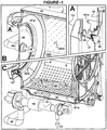
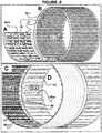
- a drum type wet or dry washing machine (1) wherein the characteristics that constitute the object of the present invention are implemented, comprises the features of claim 1, wherein perforated drum (5) inside a cylindrical tub (10) is provided, as illustrated in Figure-1, which is suitable for front loading and to rotate horizontally or inclined to the rotation axis by means of a shaft-bearing (11) provided on one side in the back or on both sides.
- drum entrance mouth (14) is shut by a door (13), either directly connected to the tub (10), or connected to an outer chassis independent from the tub (10), where an elastic bellow (12) is provided to maintain an integrity with the tub (10) and drum to keep water in the tub.
- a washing machine (1) which is object of the invention, in order to prevent keeping any unnecessary water inside the tub, drained water from the drum (5) to the tub (10) is pumped back to the drum (5) during all wet processes by means of a pump (16) while required amount or level of water exists inside the said drum (5) for a particular process.
- the fulfillment of this condition is possible either by way of providing a pump (16) big enough to pump more water than water drained out from the drum or by implementing various methods to reduce water drainage from the drum so as to correspond to the capacity of the pump employed. If a selected pump (16) has a flow-rate more than water drain-rate from the drum (5), then said pump can evacuate the space (39) between the drum and the tub (10).
- pump (16) that can handle the drained water flows from drum must be oversized for practical use. Water drainage has to be restricted from the drum during wet processes so a pump (16) can be able to pump back the drained water from the drum (5). Water permeability of a drum (5) can be restrained by means of several methods. Selected method depends on the intended use of the washing machine. Same pump (16) can be used for circulation and evacuation (43); however, if a pump is employed solely for circulation purposes, then a separate pump (17) can be used for evacuation purposes.
- the basic method of controlling drum (5) impermeability consists of diminishing permeability of drum perforations (8). If it is a perforated conventional drum, the number and/or diameter of the perforations (8) on the drum (5) have to be reduced. In order to realize the differences between standard perforations and reduced perforations in numbers and sizes are illustrated in Figure-1, wherein Figure-1C shows standard perforations (8) and Figure-1B reduced perforations (20-b). Considering the thickness of stainless metal sheet (9) of a drum (5) which has to be resist the high pressures during extraction, it is tough and uneconomical to punch the small sized perforations (20-b).
- Small perforations (20-a) can also be placed onto the front (47-a) and/or back (47-b) cover surfaces of drum (5).
- different methods described below can be implemented to restrain water permeability from a drum.
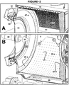
- the perforated cylindrical surface (9) of a drum (5) can be coated by sheeting (22-a) produced from an adequate material comprised from smaller perforations (21) as illustrated in Figure-2B.
- Said sheeting (22-a), shown to disclose drum perforations (8) has cut from line (C), can be manufactured from a hard material such as thin stainless metal sheet or a semi rigid material such as plastic or a soft material such as rubber.
- Coating can be applied directly onto a drum metal sheet (9) permanently or detachably.
- a coating sheet (22-a) made out of rubber or a plastic material comprises small perforations (21) matching the drum perforations (8).
- water permeability from a drum (5) is limited by way of small perforations (21)
- water drainage is continuous and the flow speed thereof may increase under the increased pressure during spinning.
- Figure-3 reveals that when coating sheet (22-c) is manufactured from an elastic material like rubber, holes of passageways do not necessarily constitute a gap.
- Perforations can be in the form of slits like "+" as shown on the sample in Figure-3 or may constitute slits (23) in various other forms.
- Slits (23) prevent water drainage up to a certain pressure level depending on the size thereof depending on the characteristics and thickness of used elastic material; but these slits start opening under the pressure during extraction, letting water drain out of the drum.
- Such elastic material (22-c) can be fixed directly onto the surface (9) or applied thereon (9) detachably.
- the back side of the coating sheet is provided with conical protrusions (25).
- a coating sheet which is mounted by way of said conical protrusions (25) that locked when inserted inside perforations (24) of a drum, can be dismounted from the surface (9) thereon (5) and can be converted into a conventional washer drum (5) or can be altered with different surface coatings (22) as per the scope of application.
- Bulges (27) may be provided in many different shapes and sizes.
- Figure-4 illustrates a coating (22-d) with pyramidal protrusions (27).
- a perforated metal sheet (19) is directly and entirely coated with rubber or plastic material (29), constituting a thickness (30) that reduces (42) the size of large perforations of a metal sheet (8-b).
- Perforations, reduced in size (42) through coating of the metal sheet (19) can be mounted onto the perforated sheet (9) of a drum.
- the surface of the material (29) used in coating said metal sheet (19) can be shaped like the coating disclosed in Figure-4 (22-d) with different shaped and sized bulging protrusions (27).
- a perforated metal sheet (9 or 19) with a material (29) such as plastic or rubber is the prevention of damages that caused by perforations (8) to delicate laundry. Since the edges of perforations (42) of plastic or rubber material (29) cannot be as sharp as those of stainless metal sheet, laundry will not be damaged during rubbing.
- One other method to achieve restrained water drainage from the drum (5) is applying a coating onto a perforated surface (9) with sheeting made by a lasting textile or compressed fibers or sheeting out of a porous rubber or plastic material or some similar substance (22-b), as illustrated in Figure-2A.
- a textile can be employed for this purpose, said textile densely woven with a synthetic fiber to enable the required amount of water drainage.
- sheeting (22-b) constituted with fibers fixated together in a way that permits a limited amount of water to pass through or sheeting (22-b) with some spongeous plastic or rubber that enables limited drainage through the pores therein.
- FIG. 1-A illustrates a method wherein a gasket (34) is mounted over a drum mouth (14) in order to restrain water drainage at low speed rotations of the drum by way of exerting pressure onto the door (13) glass (35) or onto an adequate surface over the tub neck by the pressure of water and laundry onto the gasket.
- centrifugal force increasing firstly lessens the exert of pressure force applied by gasket onto glass (35) or surface, later on separates the gasket (34) and surface (35) completely from each other by effect of high spinning rotation speed on gasket and weight protrusion (36). Fan air flow occurred by the rotation of the drum (5) helps this separation. This prevents said gasket (34) from any damage due to friction at high peripheral speeds.
- various other known passage diminishing methods can also be employed to restrict water drainage, depending on door and drum types.
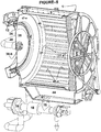
- a restrained amount of water draining from the drum (5) into the tub (10) is pumped from an outlet (15) beneath of said tub and returned to the drum (38) by means of a pump (16).
- Said pump (16) functioning by the principle of low pressure-high flow-rate, the amount of water inside a tub (10) either can be maintained at a desired minimum level or can be completely evacuated through the selection of a pump (16) that possesses a flow-rate higher than the rate of drained water out from a drum (5).
- pump (16) flow-rate can be regulated either by running the pump in an on-off manner operated by water level monitoring system or by changing motor speed of the pump through an inverter unit.
- volume (39) beneath the tub wherein an electrical heater (41) or a steam jet is provided should be filled with water throughout heating cycles. Outside these cycles while washing and rinsing, all water has to be in the drum (5) except the necessary amount which allows proper functioning of the pump (16).
- Installing a steam injection or electrical heat resistance or any kind of heat exchangers on the circulation system is another way to heat water.
- a filter (18) can be provided over the circulation line (40) to separate unsolved particles in the liquid. Adding the chemicals to the washing liquid before the circulation line (40) and the pump (16) provides a more homogeneous mixture. Heating up the tub liquid via steam injection to the circulation line (40) or through a heat exchanger provided on the circulation line eliminates the need for an extra heating apparatus and volume.
- a spray nozzle (38-b) arranged on the circulation line (40) at the drum inlet, as shown in Figure-5, can regulate the route the incoming water, spraying water onto laundry (48) during washing, and augments washing and rinsing efficiency.
- the circulation pump (16) is stopped at the end of wet processes, and water is evacuated either through the evacuation line (43), or using a separate evacuation pump (17) upon request.
- a pump (16) used for circulation purposes can also be employed for evacuation purposes.
- a valve system mounted at the pump (16) outlet is used to direct water towards the drum (5) or the evacuation line (43). Both pumps (16 and 17) can be employed simultaneously for circulation purposes.
- a volume (44) inside the tub (10) as shown in Figure-5 or outside the tub can be used to store drum water.
- the pump (16) is stopped and most of the water inside the drum (5) is stored to the said volume (44).
- drum (5) water is lessened and rubbing effect augments.
- Water in the tank (44) can be pumped back into the drum (5) by re-operating the pump (44) to remove dirt from laundry. Repeating this process at intervals will increase physical wash efficiency.
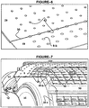
- Coating sheet (31-b) shown in Figure 7 is applied onto a drum surface (9) in a demountable manner but can also be fixed permanently.
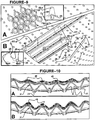
- a perforated drum surface (9) with a substance produced by several flexible pieces (Figure-8A) that can be assembled together to constitute a cylinder or in one single piece ( Figure-8B,C,D) that can be shaped as a cylinder for mounting onto said drum (5).
- Such drum surface will have the configuration as disclosed in Figure-5, wherein there is a large number of ribs or protrusions (45-a) but shorter and smaller size than conventional ribs (50).
- These small-sized ribs can be applied onto a drum surface in the form of a coating sheet (31-a) or mounted thereon separately (32) or in groups.
- the number of ribs (50) is generally 3 to 4 in conventional washing machines, sometimes 6 or maximum 8 in large-capacity ordinary industrial machines, whereas in the embodiment of this invention, small ribs (45-a) or similar protrusions (45-b, c, d) which substitute beaters (50) of conventional washing machines, are much greater in numbers.
- the height of a rib (50) employed in a conventional drum (5) corresponds to at least approximately 6% of said drum diameter
- the height (45) of a protrusion cited in the present invention corresponds to maximum approximately 6% thereof.
- Said protrusions are higher than the smooth protrusions functioning to form bulge surface which some of the producers applied on their drums using together with normal ribs.
- these protrusions (45) are not necessarily shaped as conventional ribs (50).
- Said protrusions may come into various shapes (45-b, d) and sizes, as illustrated in Figure-8-A, C.
- said protrusions (45-c) can be configured completely different from conventional and can be numerous (31-c) as illustrated in Figure-8-B.
- Drum surface shapes can be implemented either as demonstrated in Figure-8 through shaping the coating that covers the perforated cylindrical surface (9) of a drum (5) or by way of mounting pieces (51), as in Figure-9, through various methods directly onto the perforated cylindrical surface (9) of said drum (5) to form similar view as shown in Figure-8.
- Providing protrusions (45) from small pieces (51) can be a more convenient solution particularly in industrial type washing machines wherein a drum is too large to be covered with a single-piece coating material (31).
- protrusive pieces (51) produced from a material like plastic or rubber is achieved by inserting said pieces inside the perforations (8) over the perforated metal sheet (9) of a drum (5) and locking by imperforated (25) and/or perforated (26) conical protrusions, as illustrated in two different embodiments in Figure-9, or completely different installation method used for mounting of said pieces.
- Protrusive shaped profile (51-a) pieces those completing each other by gathering when they mounted over the drum sheet as shown in Figure-9-B, enables shaping (32-a) of the interior of a drum (5) with protrusions (45-e) and also covering large drum (5) perforations (8) with smaller perforations (21).
- protrusions (45-e) can be altered as shape, density, plurality, size and also number and diameter of its perforations (21), just by changing the pieces (51-a).
- Pieces (51) installed inside a drum (5) may be in various shapes and sizes.
- Figure-9-A illustrates an embodiment wherein conical protrusions (45-f) are mounted separately (51-b). If said pieces (51-b) are fixed directly onto the perforations (8), the drum (5) will have an appearance (32-b) as disclosed in Figure 8-B .
- Another advantage of using small pieces (51) is that these pieces (51) can be replaced when worn out or broken over in time.
- Restraining water drainage and shaping drum surface (32-b) can both be accomplished at the same time if protrusions (51-b) are fixed onto a drum surface one by one as shown in Figure-9-A after applying thereon a perforated surface coating (22-a) as illustrated in Figure 2-B , said coating which reduces the size of perforations over said drum surface.
- Protrusive drums (5) which are not equipped with normal size ribs (50) perform better distribution (48), thus provide better washing effect and reduce load impacts on the motor during washing.
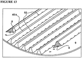
- the coating (31) shown as sectional schematic view in Figure-10 can be manufactured of a rigid or an elastic material at desired thickness.
- Said coating can be fixed permanently onto a drum metal sheet (9) or attached thereto (9) through the perforations (8) by means of inserted locking method (26).
- drum perforations are seen from the cross section of the protrusive parts (45 -g) and those protrusive parts (45-g) are placed so as to cover the drum perforations; a passage (52) located underneath the protrusive parts and corresponding to the drum perforations provides a passage of water coming from the drum to the drum perforations. Hiding the perforations underneath the protrusions prevents the contact of a delicate material to the drum perforations.
- textile (48) settles on top of protrusions (45) as shown in Figure-10-A and starts stretching towards the hollows (46), under the pressure of increasing centrifugal force by increasing extraction speed.
- Such stretching enables water to squeeze out from in-between thread fibers, clears the way for water passage, and facilitates water to pass through said fabrics before attaining the perforations.
- centrifugal force increases as drum rotation speed increase, that causes proportional compression on textile placed over a drum surface (9) and said textile blocks both water passage through textile and drum perforations that are obstructed by textile (8).
- perforations (21) may be fewer in numbers but larger in diameters.
- perforations (20-a) onto the front and/or back cover sheet (47) of a drum as in the same level with cylindrical surface by corresponding to said canals would be sufficient to let water to drain out.
- Figure-11-A shows another embodiment to be applied to smaller drums (5) to configure (33) said drum surface, wherein a perforated metal sheet (9) is first undulated and then given the shape (33-a) of a drum (5) in such a way that drum perforations (8) which formed in different sizes and shapes look like all aforementioned examples, placed inside the hollows (46) and these small ribs (45-g) shall be formed homogenously over the entire surface.
- the drum disclosed in Figure-11-B may be fabricated partially or totally from a plastic material.
- the drum interior of the drum can be manufactured with a protrusive (45-h) surface (33-b) and the exterior with a cylindrical surface (49) as shown in Figure-11-B.
- Coating a perforated metal sheet totally with some large-pieced materials (31) might be applied easily in small washing machines, but in larger machines represented in Figure-12, a handy application by using of small ribs (45-i, j) on the perforated metal sheet in between the drum perforations (8) could be better solution. If stainless steel used, said ribs (45-i) can be fixed onto the drum or welded directly over the perforated sheet (9).
- Protrusions (45) employed in drums of industrial type stone washing machines, a washing process that literally uses abrasive material like pumice stones to wear out fabrics, not only increase the physical effect of "stone washing” on treated denim fabrics and accelerate a worn-out appearance thereof, but also prevent said stones to rub the perforated metal sheet (9) and contribute the lengthening of lifetime of said drum.
- Stainless cutting-edge (45-j) protrusions are applied to a drum that performs stone-washing by means of either welding directly onto said drum or in an detachable way, as shown in Figure-12-B.
- Various shaped pieces, produced from plastic or rubber and comprise high resistance to abrade may also be substituted to stainless material and mounted likewise onto said drum.
Description
- This invention is related to washer-extractor machines and in particular to drum type washing machines that provide saving from water, energy and time and at the same time increase washing and extraction efficiency. The machine according to this invention prevents the harm of the textile caused by the drum perforations and also during the high speed spinning stage.
This invention is also related to a washing and rinsing process realized using this machine. - Washing machines are provided with various capacities for domestic and industrial applications in order to use for various processes that enable washing and/or chemical treatment of different materials, especially textile products. Besides washing machines for domestic use, there also exist several industrial types, providing physical and chemical treatments such as washing, stone-washing, dry-cleaning, bleaching, softening, and dyeing.
- Horizontal drum washing machines that constitute the object of the present application comprise a cylindrical, either horizontal or inclined with horizontal liquid tub and a perforated basket drum arranged in a same position with tub placed in it and, rotating around a shaft-bearing unit and wherein material is/are loaded. Said washing machines are divided into two groups, front loading drums wherein the drum comprises a bearing on one side only and those wherein the drum is provided with bearings on two sides.
- Aforementioned drums are in general constructed from stainless steel. Perforations provided over a drum surface enable the inflow of liquid such as water, solvents, chemicals and hot water that heated outside the drum, as well as the outflow of liquid to be discharged. Centrifugal force created by the rotation of a drum at high speed to separate a certain amount of liquid absorbed by the material and drain out through drum perforations.
- In order to fill the drum with liquid such as water or, to heat water, to mix chemicals into water, to measure water temperature, to measure water level, to drain water, and to collect liquid draining out through the drum perforations during a spinning cycle, a tub is needed outside the drum, and in order to prevent said drum to contact said tub while spinning, a space is necessary in between. When washing liquid required for a washing process is taken inside a tub, the amount of liquid filling the space between said tub and the drum corresponds to nearly 15-35% of necessary liquid. Liquid draining from a limited permeability drum can be restrained and flow back is maintained therein by means of a pump which has a higher flow-rate than that permeated water, enabling therefore an evacuation of the volume between the drum and the tub while at the same time an adequate amount of liquid existing inside the drum. The drum, which constitutes the object of the invention, provides considerable savings of water, energy, chemicals, and time by means of emptying said exterior space during a washing process. Saving of water and chemicals is important as far as consumption is concerned and also it is vital to decrease the amount of waste water contaminated with chemicals, thus preventing environmental pollution.
- During a washing process, the interaction of water and/or chemicals with washed materials inside a drum is achieved by lifting and falling movements of said materials, which obtained with the drum rotation. Conventional perforated drums contain lifter beaters which are called ribs in sizes proportional to the diameter of the drum. In washing machines using less water, rib heights varies approximately between 6 to 12% of the diameter of the drum, while this proportion reaches 12 to 20% in machines using more water. The size of said ribs should enable lifting a considerable amount of the laundry mass. In conventional washing machines, the number of ribs is limited to 6 or maximum 8. Washing is both a chemical and a physical process. One other important function of washing machines is to extract liquid from processed material by way of a centrifugal force produced from spinning of drum at high speeds. Due to centrifugal force, extracting pressure at high speeds may attain values up to 400-500G; and in the case of high capacity machines, wherein laundry stretches very tightly over ribs, and spaces remain underneath between the ribs and drum sheet, such physical pressure may applied to said laundry to stretch towards the spaces and causes damages or tearing. On the other hand, laundry over the ribs, placed during distribution, is more close to the rotation axis, means it undergoes less centrifugal force, and more liquid remains thereon. If material is lifted by means of many small ribs or protrusions scattered in very short intervals and homogeneously over the cylindrical surface of a drum, said drum constituting the object of the invention, any damage caused to textile by normal size ribs can be prevented. Height of said small ribs and protrusions indicated here is approximately between 1 to 6% of the diameter of said drum.
- Protrusive cylindrical surface of a drum also provides other advantages besides the facility of lifting washing material. Such protrusive structure, augments the physical effect while washing, helps to rotate the material in more homogeneous and more regular manner, enables better distribution of laundry inside the drum at the start of extraction and orients extracted water towards the perforations. During extraction phase, textile dispersed over a usual perforated cylindrical surface gets more and more squeezed as centrifugal force increases pressure thereon, which restrains not only water passage through the textile fibers, but also drainage ways through the drum perforations. Water drainage from a drum can be accelerated by employing adequately elevated and dense protrusions that are provided in the present invention, in which situation laundry will stretch towards the spaces between the protrusions but will not reach to block the perforations. Draining more extracted water at an equal spinning speed and equal time is provided and in return improved extraction efficiency without any change in the energy consumption is obtained.
- Many solutions have been suggested to achieve water and energy savings in washing machines. The system described in the
US Patent Application No 20070028654 is unable to provide solutions to problems such as water drainage from a drum obtained only during an extraction phase and out of one particular area, water having to pass through washed fabrics before attaining the perforations during an extraction and causing therefore insoluble particles to deposit inside said fabrics, impossibility re-heating if necessary, and the drain difficulties. Explanations recommended in theUS Patent Application No 20050015892 and theUS Patent Application No 20050028298 do not supply solutions to problems such as the backward slanting position of a drum, necessity to have said drum to spin at high speed for evacuation, water level inside said drum considerably altering the amount of water drained there from, limited amount of drainage out of said drum during both drain and extraction cycles, water passing through washed fabrics during drain and therefore depositing particles which should normally be carried away with water. Both systems suggested are difficult to put into practice because the amount of water that will pass through drum into the tub is exceed the capacity of pumps used in domestic washing machines in the case when material and water exceed the drum mouth level. Even the features of such a drum, neither placed horizontally nor cylindrically shaped as in standard and common drums, may create problems in practice. However, in order to apply all types of washing machines and washing operations, a drum should be designed so as to allow dry fabrics to be fully loaded therein and enabling water level to exceed the half level of the drum. -
DE 29 15 092 A discloses a washing-extraction machine according to the features of the preamble ofclaim 1. The invention disclosed in the present application provides savings from water, energy, chemicals and time consumption as attempted by the foregoing references, through limiting water use by the strictly necessary amount for the inner drum, enabling implementation in all types of perforated drums horizontal or inclined with the horizontal, independent from water level or the amount of fabrics loaded therein. Moreover, as explained below in several embodiments, the application of methods, corresponding to the purpose of the present invention, has been reduced to such basic essentials that no alteration is required in the production techniques of conventional and commonly used horizontal washing machines. Providing the cylindrical surface of a drum with perforations as in ordinary drums, and enabling water drainage through said perforations during both drain and extraction cycles prevent not only efficiency loss in washing and extraction but also the creation of new problems. - The invention shall be explained in detail here below with references to the attached figures, where:
- FIGURE-1 represents a perspective sectional view of a washing machine showing drum perforations in reduced size (B) and with drum mouth covered (A).
- FIGURE-2 represents a perspective sectional view of a washing machine showing drum perforations covered with a fabric (A) and with sheeting (B) that comprises perforations smaller than drum perforations (B).
- FIGURE-3 represents a perspective sectional view of drum perforations coated with sheeting that comprises a slits thereon.
- FIGURE-4 represents a perspective sectional view of drum perforations covered with sheeting that comprises perforations smaller than drum perforations, surface of said sheeting shaped in a bulging curve so as to facilitate water drainage from said drum.
- FIGURE-5 represents a perspective sectional view of numerous lifter ribs dispersed over a drum surface and a water tank arranged inside a tub.
- FIGURE-6 represents a perspective view of a perforated metal sheet that partly covers the perforated cylindrical surface of a drum, said metal sheet which is reduced in size through coating with rubber or plastic material.
- FIGURE-7 represents a perspective view of the perforated cylindrical surface of a drum coated with a material comprising protrusions.
- FIGURE-8 represents a perspective view of different protrusive materials used in coating the perforated cylindrical surface of a drum.
- FIGURE-9 represents a perspective view of various protrusive materials that are applied in pieces and assembled onto the perforated cylindrical surface of a drum and of the assemblage of said pieces.
- FIGURE-10 represents a perspective view showing the impact on laundry of a protrusive coating on the perforated cylindrical surface of a drum during extraction.
- FIGURE-11 represents a perspective view of a drum, wherein a metal sheet is given a protrusive configuration by undulating (A) or by shaping a plastic material in a mould (B), to match said metal sheet perforations with the bored zones thereof.
- FIGURE-12 represents a perspective view of the perforated cylindrical surface of a large industrial drum provided with a protrusive configuration through the addition of metal, rubber or plastic pieces.
- FIGURE-13 represents a perspective view of the cross section of two protrusions hiding the drum perforations underneath.
- In below descriptions the term "water" is to be understood to cover "liquids and chemical solvents" using in any kind of washing and dry-cleaning machines.
- The object of the present invention is to provide a drum washing machine that enables;
- during wet or dry washing processes through the use of a pump that evacuates the water in the space between a drum and a tub by pumping water from tub into the drum, said drum with reduced water permeability and said pump flow-rate capacity of which is higher than that of drained water from the drum to maintain said drum constantly with adequate water level, therefore limiting total water usage in the machine with the required amount of water within the drum, results savings from water to fill the space between the drum and the tub and the empty space of ribs and the balance cells, as well as savings in energy consumption that is required to heat such amount of water and to rotate the drum,
- to enable same material/water ratio to use water for any loading quantity independently from machine capacities to be able to use the machine for loads smaller than usual capacities under same economic conditions.
- to prevent drum perforations damaging delicate textile by means of coating said perforations with a woven fabric,
- to prevent textile being harmed during washing and especially during high speed spinning by a few number of elevated ribs that are applied in large drums, by means of substituting several low and small ribs or protrusions in various shapes for lifting said material,
- to increase physical effect on washed material and to increase water passage through perforation during extraction either through providing the interior surface of a drum with protrusive construction or coating with protrusive material or through attaching pieces so as to obtain protrusions over the perforated surface of said drum,
- to maintain a more homogeneous and balanced distribution of laundry over a cylindrical perforated drum surface during extraction by means of small ribs or protrusions dispersed homogenously thereon and uplifting said material while said drum rotates,
- to prevent damaging of delicate textile during washing by means of permeating the water through said textile while rotating same speed with drum which are spread over several small ribs or protrusions that are provided on the perforated surface during spinning of approximately at distribution speed.
- to increase rubbing effect during a washing by using of storage volume provided in said tub wherein to accumulate water by reducing water level in said drum by means of pausing pump circulation intermittently so augmenting friction between the fabrics and between said fabrics with drum protrusions.
- to provide draining big dirt pieces or dirt pellets especially occurred during washing of materials such as carpet, door/dust mat or mop; through drum perforations, by means of adequate size big holes placed between said protrusions that prevent damages on said materials by said holes.
- Water passes through drum perforations and also through drum mouth in front-loading drum washing machines. In a drum of the present invention, water flow through the perforation and drum entrance mouth is restrained in various techniques. Water with limited flow rate draining from said drum into a tub is sucked from underneath the tub by a pump, flow capacity of which is higher than the flow rate of draining water, and flow back into said drum by any way such as from the door or through the interior of the drum shaft or by way of an elastic mouth bellow situated between the tub and the drum, thus enabling a complete evacuation of the water in the space between said drum and said tub even when the drum is full with adequate water for washing. In conventionally designed drums, water passage from a drum is limited by way of reducing the diameter and/or diminishing the number of perforations or by lining with a material which has limited permeability onto the perforated drum surfaces. Said sheeting can be produced from metal, plastic, rubber or a similar substance, or a fabric or a material which although has a homogeneous structure that enables a certain amount of water oozing through its structural pores. The present invention enables to make savings from water, where conventional washing machines fill the volume between a drum and a tub, providing also savings from energy consumption to heat said water and from time to heat such water. Also, since during a washing cycle, there is no water contained inside the external tub, transmission of conduction heat loss from outer surface of the tub decreases. Absence of water outside the drum during washing results energy savings that consumed is in order to rotate the drum. Besides, reducing environmental pollution is another benefit, as savings of water lessens the amount of wastewater contaminated with chemicals.
- Various techniques can be employed to provide a protrusive configuration on the surface of perforated sheeting to coat the perforated surface of a drum. There is also the possibility of covering the cylindrical surface of a drum with a lot of pieces made of metal, plastic or rubber by assembling said pieces, so as to provide said surface with a protrusive shape. A configuration which is applied onto a drum surface so as to form a bulge thereon which facilitates water drainage through drum perforations while spinning, a protrusive configuration with protrusions in adequate heights and forms, will also augment physical impact effect on the laundry and provide rubbing effect during a washing cycle. Using small protrusions instead of normal size ribs causes higher drum rotation per same time during washing in order to rotate washing material on the same moving route. More rotation per same time means more physical effect and increase in washing efficiency. Stone washing provides special worn out process on denim fabric products. During stone washing, abrasive material used for said stone effect also abrades drum surfaces. Removable plastic protrusions protect perforated drum surface from said abrasive effect, increase physical friction and rubbing effects thus provide better and more homogeneous washing.
- Extraction process begins by distribution; fabrics which spin together with the drum stuck thereon spread onto the protrusions over the surface; as centrifuge force rises, fabrics stretch towards the space in between the protrusions and cause the fibers draw apart, which facilitates the water flow through. Lifted up by said protrusions, fabrics do not block perforations and water extracted from said fabrics can easily reach to said perforations. To prevent damaging of delicate textile during washing, protrusions in smaller size have to be applied. In this case, said protrusions can be made of elastic material. Protrusive pieces may also used to hide drum perforations completely.
- Since protrusions in various shapes and sizes dispersed along the entire surface effectuate a lifting function while washing, utilization of additional normal size ribs that are used in conventional machines, becomes unnecessary. In this embodiment, either by applying the lower sized ribs or the absence of normal size ribs in the drum also resolves the laundry damaging problems which arise due to the height of ribs during high speed extraction. By using small size ribs instead of normal usual size ribs, fabrics inside the drum are more homogeneously distributed during washing and extraction processes. Common type high ribs can also used together with small protrusions helping to rotate material. If said protrusions are in the shape of small sized ribs distributed whole drum surface and placed with an angle to the rotation axis or helically shaped they help to move laundry also to same direction with rotation axis, either from back to front or reverse. Said continuous position changing constitutes more homogenous washing process. Several protrusions of various heights as a non-homogenous surface may be used along with small protrusions to facilitate the moving of the material with the drum.
- Water in the drum exerts a buffer function between washed materials and reduces the rubbing effect thereof. Washing efficiency can be increased by decreasing water amount, which augments friction and removes dirt from said materials; then increasing water level again, allows to remove dirt by mixing with water. Rubbing the fabrics during a washing process can be repeated several times by increasing and decreasing water amount. If the amount of water is to be decreased, the pump circulating water from the tub into the drum is paused, letting water to store inside the tub or a tank installed either within or outside the tub. When the pump starts running, the drum is refilled with water from the tank. For present invention volume of the space between drum and tub is not important anymore because said volume does not keep water anymore.
- In order to control water drainage, the perforated surface of a cylindrical drum can also be coated with an adequate fabric. Another purpose of coating a perforated drum surface with fabric is to form a screen over the perforations to prevent any damage to delicate fabrics which may caused by burrs present inside the holes or the cutting edges thereof.
- A drum type wet or dry washing machine (1), wherein the characteristics that constitute the object of the present invention are implemented, comprises the features of
claim 1, wherein perforated drum (5) inside a cylindrical tub (10) is provided, as illustrated in Figure-1, which is suitable for front loading and to rotate horizontally or inclined to the rotation axis by means of a shaft-bearing (11) provided on one side in the back or on both sides. In industrial or domestic front-loading washing machines, drum entrance mouth (14) is shut by a door (13), either directly connected to the tub (10), or connected to an outer chassis independent from the tub (10), where an elastic bellow (12) is provided to maintain an integrity with the tub (10) and drum to keep water in the tub. In drums with bearings on both sides, door is provided both in the drum and in the tub in industrial machines. In spite of some differences in size and details, principal components of domestic front-loading machines are similar with industrial washing and dry-cleaning machines. To simplify figures and descriptions, front-loading domestic washers (1) are used in the present application. Embodiments illustrated and described below through domestic type washers can be implemented in all industrial washing machines, both in those with single side bearing and with both sides bearing. - In a washing machine (1) which is object of the invention, in order to prevent keeping any unnecessary water inside the tub, drained water from the drum (5) to the tub (10) is pumped back to the drum (5) during all wet processes by means of a pump (16) while required amount or level of water exists inside the said drum (5) for a particular process. The fulfillment of this condition is possible either by way of providing a pump (16) big enough to pump more water than water drained out from the drum or by implementing various methods to reduce water drainage from the drum so as to correspond to the capacity of the pump employed. If a selected pump (16) has a flow-rate more than water drain-rate from the drum (5), then said pump can evacuate the space (39) between the drum and the tub (10). However, considering the number of drum (5) perforations (8) and diameters of a conventional washer, pump (16) that can handle the drained water flows from drum must be oversized for practical use. Water drainage has to be restricted from the drum during wet processes so a pump (16) can be able to pump back the drained water from the drum (5). Water permeability of a drum (5) can be restrained by means of several methods. Selected method depends on the intended use of the washing machine. Same pump (16) can be used for circulation and evacuation (43); however, if a pump is employed solely for circulation purposes, then a separate pump (17) can be used for evacuation purposes.
- The basic method of controlling drum (5) impermeability consists of diminishing permeability of drum perforations (8). If it is a perforated conventional drum, the number and/or diameter of the perforations (8) on the drum (5) have to be reduced. In order to realize the differences between standard perforations and reduced perforations in numbers and sizes are illustrated in Figure-1, wherein Figure-1C shows standard perforations (8) and Figure-1B reduced perforations (20-b). Considering the thickness of stainless metal sheet (9) of a drum (5) which has to be resist the high pressures during extraction, it is tough and uneconomical to punch the small sized perforations (20-b). Small perforations (20-a) can also be placed onto the front (47-a) and/or back (47-b) cover surfaces of drum (5). Apart from reducing the size of perforations (8) on the metal surface (9) of a drum (5), different methods described below can be implemented to restrain water permeability from a drum. The perforated cylindrical surface (9) of a drum (5) can be coated by sheeting (22-a) produced from an adequate material comprised from smaller perforations (21) as illustrated in Figure-2B. Said sheeting (22-a), shown to disclose drum perforations (8) has cut from line (C), can be manufactured from a hard material such as thin stainless metal sheet or a semi rigid material such as plastic or a soft material such as rubber. Coating can be applied directly onto a drum metal sheet (9) permanently or detachably. A coating sheet (22-a) made out of rubber or a plastic material comprises small perforations (21) matching the drum perforations (8). In methods wherein water permeability from a drum (5) is limited by way of small perforations (21), water drainage is continuous and the flow speed thereof may increase under the increased pressure during spinning. Figure-3 reveals that when coating sheet (22-c) is manufactured from an elastic material like rubber, holes of passageways do not necessarily constitute a gap. Perforations can be in the form of slits like "+" as shown on the sample in Figure-3 or may constitute slits (23) in various other forms. Slits (23) prevent water drainage up to a certain pressure level depending on the size thereof depending on the characteristics and thickness of used elastic material; but these slits start opening under the pressure during extraction, letting water drain out of the drum. Such elastic material (22-c) can be fixed directly onto the surface (9) or applied thereon (9) detachably. As shown in detail in Figure-3-A, the back side of the coating sheet is provided with conical protrusions (25). A coating sheet which is mounted by way of said conical protrusions (25) that locked when inserted inside perforations (24) of a drum, can be dismounted from the surface (9) thereon (5) and can be converted into a conventional washer drum (5) or can be altered with different surface coatings (22) as per the scope of application. During evacuation cycle of a cleaning-aimed washing process, water must drain out from the drum (5) through the perforations thereon in order to remove particles, at least partly, which do not dissolve in water. The specific embossed coating sheet (22-d), manufactured from a material such as rubber or plastic shown in Figure-4, that has a fastener system (26) to fix it onto the perforated drum surface from holes which not only well fits to the drum perforations (8) but also have passages through and facilitates drainage from a drum during extraction because of the inclined surface around the small perforations (21) placed on bottom of the hollow (28) between bulging protrusions (27). Bulges (27) may be provided in many different shapes and sizes. For an example, Figure-4 illustrates a coating (22-d) with pyramidal protrusions (27). Another method for reducing drum perforations (8) is disclosed in Figure-6, wherein a perforated metal sheet (19) is directly and entirely coated with rubber or plastic material (29), constituting a thickness (30) that reduces (42) the size of large perforations of a metal sheet (8-b). Perforations, reduced in size (42) through coating of the metal sheet (19) can be mounted onto the perforated sheet (9) of a drum. The surface of the material (29) used in coating said metal sheet (19) can be shaped like the coating disclosed in Figure-4 (22-d) with different shaped and sized bulging protrusions (27).
- Another benefit of coating a perforated metal sheet (9 or 19) with a material (29) such as plastic or rubber is the prevention of damages that caused by perforations (8) to delicate laundry. Since the edges of perforations (42) of plastic or rubber material (29) cannot be as sharp as those of stainless metal sheet, laundry will not be damaged during rubbing.
- One other method to achieve restrained water drainage from the drum (5) is applying a coating onto a perforated surface (9) with sheeting made by a lasting textile or compressed fibers or sheeting out of a porous rubber or plastic material or some similar substance (22-b), as illustrated in Figure-2A. A textile can be employed for this purpose, said textile densely woven with a synthetic fiber to enable the required amount of water drainage. There is also the possibility of employing sheeting (22-b) constituted with fibers fixated together in a way that permits a limited amount of water to pass through or sheeting (22-b) with some spongeous plastic or rubber that enables limited drainage through the pores therein. In conventional drums during a washing process, fine and delicate textile worn out through perforation (8) edges, even penetrating inside, and can be damaged by the sharp edges of said perforations (8) or by the burrs formed therein. Another advantage of coating the surface with a textile (22-b) or with some other water permeable substance is to prevent the drum perforations (8) to damage laundry by way of stopping all contacts between said perforations (8) and said textile.
- When water drains out from a drum (5) just through a textile or water permeable material sheeting (22-b), particles that should be removed together with water may remain inside because said sheeting (22-b) functions like a filter that permits the flow of water only. This problem can be resolved through providing the drum (5), in addition to a water permeable textile coating (22-b), drum front (47-a) and/or back (47-b) cover surfaces are provided with small perforations (20-a), then particles suspended in water can be discharged from the drum (5) during all of the wet cycles; therefore, during extraction, particles do not cause a trouble when water pass through the textile (22-b) or through the fissured elastic coating (22-c) or through any other water permeable substance (22-b) covering the cylindrical surface (9). Selecting a method may vary by use purpose of a washing machine (1), and in some cases different methods can be combined in the same drum (5).
- A second passage from the drum towards the tub is through the drum mouth (14). As demonstrated in the detail frame (Figure-1-A), there is a space between the immovable tub (10) and the rotary drum (5), wherein water can flow without obstruction. Water drainage through said opening (37) also needs to be reduced however it is not necessary to obstruct completely. Figure-1-A illustrates a method wherein a gasket (34) is mounted over a drum mouth (14) in order to restrain water drainage at low speed rotations of the drum by way of exerting pressure onto the door (13) glass (35) or onto an adequate surface over the tub neck by the pressure of water and laundry onto the gasket. During extraction, centrifugal force increasing firstly lessens the exert of pressure force applied by gasket onto glass (35) or surface, later on separates the gasket (34) and surface (35) completely from each other by effect of high spinning rotation speed on gasket and weight protrusion (36). Fan air flow occurred by the rotation of the drum (5) helps this separation. This prevents said gasket (34) from any damage due to friction at high peripheral speeds. Besides this particular method given as example, various other known passage diminishing methods can also be employed to restrict water drainage, depending on door and drum types.
- As illustrated in Figure-1, a restrained amount of water draining from the drum (5) into the tub (10) is pumped from an outlet (15) beneath of said tub and returned to the drum (38) by means of a pump (16). Said pump (16) functioning by the principle of low pressure-high flow-rate, the amount of water inside a tub (10) either can be maintained at a desired minimum level or can be completely evacuated through the selection of a pump (16) that possesses a flow-rate higher than the rate of drained water out from a drum (5). In order to keep water amount at desired level, pump (16) flow-rate can be regulated either by running the pump in an on-off manner operated by water level monitoring system or by changing motor speed of the pump through an inverter unit. For heating water, volume (39) beneath the tub wherein an electrical heater (41) or a steam jet is provided, should be filled with water throughout heating cycles. Outside these cycles while washing and rinsing, all water has to be in the drum (5) except the necessary amount which allows proper functioning of the pump (16). Installing a steam injection or electrical heat resistance or any kind of heat exchangers on the circulation system is another way to heat water. If requested, a filter (18) can be provided over the circulation line (40) to separate unsolved particles in the liquid. Adding the chemicals to the washing liquid before the circulation line (40) and the pump (16) provides a more homogeneous mixture. Heating up the tub liquid via steam injection to the circulation line (40) or through a heat exchanger provided on the circulation line eliminates the need for an extra heating apparatus and volume.
- A spray nozzle (38-b) arranged on the circulation line (40) at the drum inlet, as shown in Figure-5, can regulate the route the incoming water, spraying water onto laundry (48) during washing, and augments washing and rinsing efficiency. The circulation pump (16) is stopped at the end of wet processes, and water is evacuated either through the evacuation line (43), or using a separate evacuation pump (17) upon request. In domestic type washing machines, a pump (16) used for circulation purposes can also be employed for evacuation purposes. For this purpose a valve system mounted at the pump (16) outlet is used to direct water towards the drum (5) or the evacuation line (43). Both pumps (16 and 17) can be employed simultaneously for circulation purposes.
- As water amount is reduced inside a drum (5) during wet processes like washing and rinsing, physical friction increases between washed materials (48), providing a better rubbing thereof. To enable this, a volume (44) inside the tub (10) as shown in Figure-5 or outside the tub, can be used to store drum water. During washing, the pump (16) is stopped and most of the water inside the drum (5) is stored to the said volume (44). Thus, as water is stored inside the tank, drum (5) water is lessened and rubbing effect augments. Water in the tank (44) can be pumped back into the drum (5) by re-operating the pump (44) to remove dirt from laundry. Repeating this process at intervals will increase physical wash efficiency.
- As illustrated in Figure-7, coating of the cylindrical surface (9) of a drum (5) with plastic, rubber or similar substance (31-b), augments physical effects in washing cycles and also extraction efficiency, said coating comprises from a perforated (21) surface with distinctly protrusions (45-b) in different shapes and sizes. In the embodiment shown in Figure-7, a coating sheet (31-b) applied onto the perforated surface (9) of a drum (5) for shaping purposes, restrains at the same time water drainage as conical lockers (26), which are fixed through the drum perforations in order to lock said material (31-b) onto the surface (9), comprise perforations (21) in the middle which are smaller than drum perforations (8). Coating sheet (31-b) shown in
Figure 7 is applied onto a drum surface (9) in a demountable manner but can also be fixed permanently. There is also the possibility of coating a perforated drum surface (9) with a substance produced by several flexible pieces (Figure-8A) that can be assembled together to constitute a cylinder or in one single piece (Figure-8B,C,D) that can be shaped as a cylinder for mounting onto said drum (5). By providing in adequate size, shape, and quantity of protrusions (45) which cover the cylindrical surface (9) of a drum (5) can rotate and lift up the laundry (48) inside said drum without necessitating the use of normal size lifter ribs (50), which are currently employed in horizontal washing machines. Such drum surface will have the configuration as disclosed in Figure-5, wherein there is a large number of ribs or protrusions (45-a) but shorter and smaller size than conventional ribs (50). These small-sized ribs can be applied onto a drum surface in the form of a coating sheet (31-a) or mounted thereon separately (32) or in groups. The number of ribs (50) is generally 3 to 4 in conventional washing machines, sometimes 6 or maximum 8 in large-capacity ordinary industrial machines, whereas in the embodiment of this invention, small ribs (45-a) or similar protrusions (45-b, c, d) which substitute beaters (50) of conventional washing machines, are much greater in numbers. While the height of a rib (50) employed in a conventional drum (5) corresponds to at least approximately 6% of said drum diameter, the height (45) of a protrusion cited in the present invention corresponds to maximum approximately 6% thereof. Said protrusions are higher than the smooth protrusions functioning to form bulge surface which some of the producers applied on their drums using together with normal ribs. Besides, as can be seen in Figure-5 and Figure-8-D, these protrusions (45) are not necessarily shaped as conventional ribs (50). Said protrusions may come into various shapes (45-b, d) and sizes, as illustrated in Figure-8-A, C. Furthermore, said protrusions (45-c) can be configured completely different from conventional and can be numerous (31-c) as illustrated in Figure-8-B. Drum surface shapes can be implemented either as demonstrated in Figure-8 through shaping the coating that covers the perforated cylindrical surface (9) of a drum (5) or by way of mounting pieces (51), as in Figure-9, through various methods directly onto the perforated cylindrical surface (9) of said drum (5) to form similar view as shown in Figure-8. Providing protrusions (45) from small pieces (51) can be a more convenient solution particularly in industrial type washing machines wherein a drum is too large to be covered with a single-piece coating material (31). Installation of protrusive pieces (51) produced from a material like plastic or rubber, is achieved by inserting said pieces inside the perforations (8) over the perforated metal sheet (9) of a drum (5) and locking by imperforated (25) and/or perforated (26) conical protrusions, as illustrated in two different embodiments in Figure-9, or completely different installation method used for mounting of said pieces. Protrusive shaped profile (51-a) pieces those completing each other by gathering when they mounted over the drum sheet as shown in Figure-9-B, enables shaping (32-a) of the interior of a drum (5) with protrusions (45-e) and also covering large drum (5) perforations (8) with smaller perforations (21). When necessary, protrusions (45-e) can be altered as shape, density, plurality, size and also number and diameter of its perforations (21), just by changing the pieces (51-a). Pieces (51) installed inside a drum (5) may be in various shapes and sizes. Figure-9-A illustrates an embodiment wherein conical protrusions (45-f) are mounted separately (51-b). If said pieces (51-b) are fixed directly onto the perforations (8), the drum (5) will have an appearance (32-b) as disclosed inFigure 8-B . Another advantage of using small pieces (51) is that these pieces (51) can be replaced when worn out or broken over in time. Restraining water drainage and shaping drum surface (32-b) can both be accomplished at the same time if protrusions (51-b) are fixed onto a drum surface one by one as shown in Figure-9-A after applying thereon a perforated surface coating (22-a) as illustrated inFigure 2-B , said coating which reduces the size of perforations over said drum surface. Protrusive drums (5) which are not equipped with normal size ribs (50) perform better distribution (48), thus provide better washing effect and reduce load impacts on the motor during washing. The coating (31) shown as sectional schematic view in Figure-10 can be manufactured of a rigid or an elastic material at desired thickness. Said coating can be fixed permanently onto a drum metal sheet (9) or attached thereto (9) through the perforations (8) by means of inserted locking method (26). As shown inFigure 13 , drum perforations are seen from the cross section of the protrusive parts (45 -g) and those protrusive parts (45-g) are placed so as to cover the drum perforations; a passage (52) located underneath the protrusive parts and corresponding to the drum perforations provides a passage of water coming from the drum to the drum perforations. Hiding the perforations underneath the protrusions prevents the contact of a delicate material to the drum perforations. - At the end of distribution, textile (48) settles on top of protrusions (45) as shown in Figure-10-A and starts stretching towards the hollows (46), under the pressure of increasing centrifugal force by increasing extraction speed. Such stretching enables water to squeeze out from in-between thread fibers, clears the way for water passage, and facilitates water to pass through said fabrics before attaining the perforations. Whereas, in conventional washing machines, during extraction, centrifugal force increases as drum rotation speed increase, that causes proportional compression on textile placed over a drum surface (9) and said textile blocks both water passage through textile and drum perforations that are obstructed by textile (8). Supplying protrusions (45) at adequate height and density will keep laundry away from perforations (21) by spreading over protrusions during washing and extraction cycles. Water will easily reach the perforations (21) and drain out from the drum (5) because fabrics (48) will not be able to block said perforations. In such drums, as demonstrated in Figure-5, perforations (21) may be fewer in numbers but larger in diameters. In case of an appropriate construction of protrusions and canals in between, there is no necessity of placing perforations on a cylindrical surface, placing of these perforations (20-a) onto the front and/or back cover sheet (47) of a drum as in the same level with cylindrical surface by corresponding to said canals would be sufficient to let water to drain out. Since, during extraction, removed water from laundry, finds its way to the perforations without facing any obstruction in the hollows (46) between the protrusions, required time to attain the desired humidity level is also reduced. Figure-11-A shows another embodiment to be applied to smaller drums (5) to configure (33) said drum surface, wherein a perforated metal sheet (9) is first undulated and then given the shape (33-a) of a drum (5) in such a way that drum perforations (8) which formed in different sizes and shapes look like all aforementioned examples, placed inside the hollows (46) and these small ribs (45-g) shall be formed homogenously over the entire surface. The drum disclosed in Figure-11-B may be fabricated partially or totally from a plastic material. When the perforated surface of a drum is made of a plastic material, the drum interior of the drum can be manufactured with a protrusive (45-h) surface (33-b) and the exterior with a cylindrical surface (49) as shown in Figure-11-B. Coating a perforated metal sheet totally with some large-pieced materials (31) might be applied easily in small washing machines, but in larger machines represented in Figure-12, a handy application by using of small ribs (45-i, j) on the perforated metal sheet in between the drum perforations (8) could be better solution. If stainless steel used, said ribs (45-i) can be fixed onto the drum or welded directly over the perforated sheet (9). In cleaning-purposed washing machines wherein water level is low, sufficient number of small ribs (45) can rotate washing material alone but will not be sufficient to rotate the entire floating material in machines wherein water level is higher. Normal size ribs (50) are also required in this case in addition to said small ribs (45), as can be observed in Figure-12-A. Sizes, shapes, and densities of protrusions (45) in side the drum must be provided to prevent any damages on the textile (48). Protrusions (45), employed in drums of industrial type stone washing machines, a washing process that literally uses abrasive material like pumice stones to wear out fabrics, not only increase the physical effect of "stone washing" on treated denim fabrics and accelerate a worn-out appearance thereof, but also prevent said stones to rub the perforated metal sheet (9) and contribute the lengthening of lifetime of said drum. (9). Stainless cutting-edge (45-j) protrusions are applied to a drum that performs stone-washing by means of either welding directly onto said drum or in an detachable way, as shown in Figure-12-B. Various shaped pieces, produced from plastic or rubber and comprise high resistance to abrade, may also be substituted to stainless material and mounted likewise onto said drum. Employing plastic pieces (51-a, b) in stone-washing drums, illustrated as example in Figure-9, augment physical effect and prevent at the same time the wearing out of drum sheet (9). In time, protrusions (51) which worn out under the abrasive effect of stones, can be replaced with new ones (51).
| 1 | Washing machine | 32-b | Small conical | |
| 5 | Drum | 32-c | | |
| 8 | Large drum perforations | 32-d | Small | |
| 9 | Perforated drum surface | 33-a | Corrugated | |
| 10 | Water tub | 33-b | Corrugated plastic surface | |
| 11 | Shaft-bearing | 34 | | |
| 12 | | 35 | | |
| 13 | | 36 | Weight protrusion on a sealing | |
| 14 | | 37 | Drum-tub | |
| 15 | | 38 | Return to | |
| 16 | Circulation pump | 38- | Spray nozzle | |
| 17 | | 39 | | |
| 18 | | 40 | | |
| 19 | Metal sheet coated with plastic- | 41 | Electrical heater | |
| 20-a | Small perforations over front- | 42 | Perforation on a plastic-rubber sheet | |
| 20-b | Small perforations over drum | 43 | | |
| 21 | Perforations reduced in | 44 | Water storage tank | |
| 22-a | Flat sheeting with small perforations | 45-a | Rib shaped protrusions | |
| 22-b | Fabric or pores material | 45-b | Pyramidal protrusions | |
| 22-c | Sheeting with slits | 45-c | Conical protrusions | |
| 22-d | Bulging sheeting with small perforations | 45- | Sheet protrusions | |
| 23 | Slits | 45-e | Profiled | |
| 24 | Drum locker perforations | 45-f | Individual | |
| 25 | Conical locker | 45-g,h | Shaped | |
| 26 | Perforated bulging locker | 45-i,j | Ribs added to the | |
| 27 | Bulging protrusions | 45-k | Protrusions having water flow gaps underneath | |
| 28 | Bores of a | 46 | | |
| 29 | Plastic-rubber coating | 47-a | | |
| 30 | Coating width on perforated metal sheet | 47-b | Rear drum cover | |
| 31-a | Rib shaped sheeting with | 48 | Processed material | |
| 31-b | Protrusive sheeting with | 49 | Perforated plastic | |
| 31-c | Conically protrusive sheeting with | 50 | Usual normal size rib | |
| 31-d | Protrusive sheet with | 51 | Small protrusive plastic pieces | |
| 32-a | Plastic pieces with | 52 | Water flow passage beneath the protrusions |
Claims (24)
- A washing-extraction machine (1) comprising:a liquid tub (10) positioned either horizontally or inclined with the horizontal,a perforated drum (5), which rotates in the liquid tub (10) around a shaft-bearing system (11),characterized in thata cylindrical surface (9) of the perforated drum (5) is provided with a ribbed constitution in order to obtain a surface with dense protrusions (45) and hollows (46) in various shapes and sizes;in that the height of said protrusions (45) is less than 6% of the diameter of said drum (5);wherein the protrusions (45) on the cylindrical surface of said drum (5) are placed side by side to constitute hollows (46) in between thereof; andwherein the drum perforations (21) provided on the cylindrical surface (9) of said drum (5) are arranged in the hollows (46) between said protrusions (45), and wherein said protrusions (45) are adequately elevated and densely provided such that laundry that is stretched towards the hollows between the protrusions (45) will not reach to block the perforations (21).
- A machine as claimed in Claim 1, characterized in that said protrusions (45) are solely sufficient enough to move the materials being washed along with the drum (5).
- A machine as in Claim 1, characterized in that a metal sheet which constitutes the cylindrical surface (9) of said drum (5) is undulated (33-a) with corrugated indents and protrusions (45-g).
- A machine as in Claim 1, characterized in that the cylindrical surface (9) of said drum (5) is manufactured of a plastic material (33-b) having undulated shape with indents and protrusions (45).
- A machine as in Claim 1, characterized in that a coating (31) formed undulated on the cylindrical surface (9) of said drum (5) comprises of a single piece (31- a, b, c) or several pieces (31-b) fixed permanently or detachably on the surface.
- A machine as in Claims 1 to 5, characterized in that said protrusions (45) are provided on the cylindrical surface of said drum (5) either solely in lieu of normal size ribs (50) or in addition to conventional normal size ribs (50).
- A machine as in Claims 1 to 6, characterized in that said protrusions (45) are arranged over the entire interior surface of said drum (5) in the form of small ribs (45- a d, e, g, h, i, j).
- A machine as in Claim 7, characterized in that said small size ribs (45) are placed onto the said drum (5) surface with an angle with rotation axis or in helical form to move laundry in the same direction of rotation axis, either from back to front or reverse, during drum rotation.
- A machine as in Claim 7, characterized in that said small size protrusions (45) are placed over the surface of said drum (5) to completely cover the drum perforations (21) however to allow the flow of liquid underneath gap to reach the drum perforations.
- A machine as in Claim 7, characterized in that said protrusions (45) are regionally elevated in various heights to form non-homogeneous surface shape that helps to lift up the material up.
- A machine as in Claim 1, characterized in that the drum perforations (21) are sized so as to allow the large dirt pieces or pellets leave the drum.
- A machine as in Claim 1, characterized in that the drum perforations (21) are sized small enough to reduce liquid permeability of the drum.
- A machine as in above Claims,
characterized in that a pump (16) is provided to be operated under control mounted onto a circulation line (40) that while a required level or amount of liquid for washing or rinsing is provided in the drum (5) enables to decrease the level of tub liquid or to keep the level of the tub liquid at desired level or to evacuate the tub liquid completely when needed,
wherein tub liquid that exists in a volume (39) between said drum (5) and tub (10) and that drains from the drum (5) into the tub (10) is sucked from tub (10) in order to pump said liquid back to the drum (5), wherein
said pump (16) has a higher flow-rate capacity than drain rate of liquid from said drum (5) into the tub (10); and in that
permeability of said drum (5) is restrained to enable the pump (16) to change the level or to keep the level of tub liquid in the volume (39) between the tub (10) and the drum (5) as desired or to evacuate said tub liquid completely when requested by the said pump (16),
wherein the quantities and sizes of said drum perforations (20) are provided in such a way that the drain rate of the liquid from said perforations is less than the flow rate of the pump (16) which is used to pump the liquid back into the drum (5). - A machine as in Claim 13, characterized in that said circulation line (40) is accessing into said drum (5) through a door (35) or a drum-tub mouth bellow (12) or a drum shaft (11).
- A machine as in Claim 13, characterized in that chemicals are added to the washing liquid before the circulation line (40) and before the pump (16) is operated; tub liquid is heated be means of steam injector or a heat exchanger on the circulation line (40) and the particulates in the circulation liquid are filtered through a filter (18).
- A machine as in Claim 13, characterized in that in said drum (5) number and/or sizes of liquid passage perforations (20) of the drum (5) effecting said drum permeability, are reduced compared to conventional drums.
- A machine as in Claim 13, characterized in that in order to restrain the permeability of said drum (5), perforated surfaces (9) of said drum are coated with a permanent or detachable material to limit water flow and that shapes, quantities and sizes of said coating (22) perforations (21) are provided in a way to provide the drain rate of the liquid from said perforations is less than the flow rate of the pump (16) which is used to pump the liquid back into the drum (5).
- A machine as in Claim 17, characterized in that said coating (22) is manufactured of various material like rubber, plastic, metal, woven or any other material having limited liquid permeability due to its porous structure.
- A machine as in Claim 18, characterized in that said rubber, plastic or similar surface coating (22-d) comprises bulgy parts (27) of various shapes and sizes in between said perforations (21).
- A machine as in Claim 18, characterized in that small slits (23) corresponding to drum perforations (8), without leaving any space there between are provided on the said rubber or plastic coating.
- A machine as in Claim 13, characterized in that in order to restrict liquid permeability of said drum (5) the passage (37) around the drum mouth (14) to the tub (10) is covered with a suitable sealing gasket (34).
- A machine as in Claim 21, characterized in that said gasket (34) is mounted onto the drum mouth (14) to rotate with said drum (5), and by touching either specific surface of the tub or the tub door (13) or a suitable surface (35) in order to restrain the liquid passage way and if desired said gasket (34) is provided with a weight protrusion (36) to decrease or totally eliminate pressure caused by centrifugal force exerted during extraction.
- A machine as claimed in above Claims, characterized in that the parts used over the perforated surface (9) of said drum are configured to constitute a profile (45-e) including protrusions (45) and also the hollow zone (46), said profile covering drum perforations (8) as well; and bores (21) in the hollow zone (46) matching with drum perforations, in less numbers and/or smaller in diameters than perforations of conventional drums for reducing liquid permeability of the drum.
- A washing and rinsing process in a washing machine as claimed in Claims 1 to 13, characterized in that in order to prevent any harm to delicate materials; while the drum rotates faster than its distribution speed, circulation liquid is transmitted throughout the textile which is spread onto the protrusions placed on the drum surface.
Priority Applications (1)
| Application Number | Priority Date | Filing Date | Title |
|---|---|---|---|
| EP17180522.9A EP3252207B1 (en) | 2007-11-12 | 2008-11-12 | Washing machine |
Applications Claiming Priority (3)
| Application Number | Priority Date | Filing Date | Title |
|---|---|---|---|
| TR200707754 | 2007-11-12 | ||
| PCT/TR2008/000127 WO2009064262A2 (en) | 2007-11-12 | 2008-11-12 | Washer-extractor machine |
| TR200808605 | 2008-11-12 |
Related Child Applications (1)
| Application Number | Title | Priority Date | Filing Date |
|---|---|---|---|
| EP17180522.9A Division EP3252207B1 (en) | 2007-11-12 | 2008-11-12 | Washing machine |
Publications (2)
| Publication Number | Publication Date |
|---|---|
| EP2229475A2 EP2229475A2 (en) | 2010-09-22 |
| EP2229475B1 true EP2229475B1 (en) | 2017-07-12 |
Family
ID=40639361
Family Applications (2)
| Application Number | Title | Priority Date | Filing Date |
|---|---|---|---|
| EP17180522.9A Active EP3252207B1 (en) | 2007-11-12 | 2008-11-12 | Washing machine |
| EP08851033.4A Active EP2229475B1 (en) | 2007-11-12 | 2008-11-12 | Washer-extractor machine |
Family Applications Before (1)
| Application Number | Title | Priority Date | Filing Date |
|---|---|---|---|
| EP17180522.9A Active EP3252207B1 (en) | 2007-11-12 | 2008-11-12 | Washing machine |
Country Status (10)
| Country | Link |
|---|---|
| US (2) | US20110100068A1 (en) |
| EP (2) | EP3252207B1 (en) |
| JP (1) | JP4923145B2 (en) |
| KR (1) | KR101319148B1 (en) |
| CN (1) | CN101910502B (en) |
| BR (1) | BRPI0817412A2 (en) |
| EA (1) | EA017938B1 (en) |
| ES (1) | ES2642871T3 (en) |
| MX (1) | MX353091B (en) |
| WO (1) | WO2009064262A2 (en) |
Cited By (2)
| Publication number | Priority date | Publication date | Assignee | Title |
|---|---|---|---|---|
| WO2020256648A1 (en) * | 2019-06-18 | 2020-12-24 | Tulga Simsek | Washing machine water channels on drum surface |
| WO2020256649A1 (en) * | 2019-06-18 | 2020-12-24 | Tulga Simsek | Washing machine motor systems on the drum |
Families Citing this family (41)
| Publication number | Priority date | Publication date | Assignee | Title |
|---|---|---|---|---|
| US20120291302A1 (en) * | 2011-05-16 | 2012-11-22 | Bsh Home Appliances Corporation | Noise-reducing laundry drum for a household appliance |
| EP2749684A4 (en) * | 2011-08-22 | 2015-01-07 | Haier Group Corp | Washing machine and washing method |
| CN102535101B (en) * | 2011-12-31 | 2013-10-23 | 无锡小天鹅股份有限公司 | Composite inner barrel of washing machine |
| CN102706113B (en) * | 2012-05-25 | 2014-10-22 | 句容市红掌食品有限公司 | Self-heating type feather dehydrator |
| KR102206465B1 (en) * | 2013-07-18 | 2021-01-21 | 엘지전자 주식회사 | Washing machine and Controlling method for the same |
| CN104420124B (en) * | 2013-08-29 | 2018-05-22 | 青岛海尔滚筒洗衣机有限公司 | A kind of washing machine inner tub and washing machine |
| DE102014217121A1 (en) * | 2014-08-28 | 2016-03-03 | BSH Hausgeräte GmbH | Laundry care device with a feeder |
| CH710594B1 (en) * | 2015-01-06 | 2018-12-14 | V Zug Ag | Washing machine with reduced water consumption. |
| CN105986427B (en) * | 2015-01-27 | 2019-10-01 | 青岛海尔洗衣机有限公司 | A kind of washing machine double-ended draining pump |
| ITUB20153009A1 (en) * | 2015-08-07 | 2017-02-07 | Nexia S R L | ABRASIVE BASKET FOR AN AGING CLOTHES DEVICE AND AGING EQUIPMENT INCLUDING THIS BASKET |
| US10400901B2 (en) | 2016-05-17 | 2019-09-03 | Henry Barkley Salem | Valves and methods of access |
| KR102396321B1 (en) * | 2016-07-12 | 2022-05-10 | 삼성전자주식회사 | Washing machine |
| US10016763B1 (en) | 2016-12-24 | 2018-07-10 | Murray J. Moran | Sand treatment systems and methods |
| GB201704736D0 (en) * | 2017-03-24 | 2017-05-10 | Xeros Ltd | Treatment apparatus and method |
| KR102493162B1 (en) * | 2017-11-08 | 2023-01-27 | 엘지전자 주식회사 | Laundry treating appratus and controlling method thereof |
| US10465324B1 (en) * | 2018-05-31 | 2019-11-05 | Haier Us Appliance Solutions, Inc. | Method for detecting a low water level in a washing machine appliance |
| RU2770757C1 (en) * | 2018-06-27 | 2022-04-21 | ЭлДжи ЭЛЕКТРОНИКС ИНК. | Washing machine |
| EP3587652A1 (en) | 2018-06-27 | 2020-01-01 | LG Electronics Inc. -1- | Washing machine |
| AU2019329626A1 (en) * | 2018-08-30 | 2021-05-06 | Lg Electronics Inc. | Washing machine |
| WO2020130523A1 (en) * | 2018-12-18 | 2020-06-25 | 삼성전자주식회사 | Washing machine |
| CN109827389B (en) * | 2019-01-28 | 2021-02-19 | 江苏华艺服饰有限公司 | Wringing-squeezing type dewatering structure of fabric dewatering device |
| EP3987109A1 (en) | 2019-06-18 | 2022-04-27 | Texdreme Arastirma Gelistirme Anonim Sirketi | Washing machine mechanical balance system with metal weights |
| EP3987107A1 (en) * | 2019-06-18 | 2022-04-27 | Texdreme Arastirma Gelistirme Anonim Sirketi | Washing machine water collection chamber |
| WO2020256656A1 (en) | 2019-06-18 | 2020-12-24 | Tulga Simsek | Washing machine dynamic parts in the drum |
| WO2020256655A1 (en) | 2019-06-18 | 2020-12-24 | Tulga Simsek | Water tub free washing machine |
| EP3987111A1 (en) | 2019-06-18 | 2022-04-27 | Texdreme Arastirma Gelistirme Anonim Sirketi | Indirect heating directly from drum surface |
| WO2020256654A1 (en) | 2019-06-18 | 2020-12-24 | Tulga Simsek | Washing machine electrical systems on the drum |
| EP3987108A1 (en) | 2019-06-18 | 2022-04-27 | Texdreme Arastirma Gelistirme Anonim Sirketi | Washing machine dynamic systems in the drum |
| WO2020256651A1 (en) | 2019-06-18 | 2020-12-24 | Tulga Simsek | Washing machine mechanical balance system with liquid container weights |
| WO2020256646A1 (en) | 2019-06-18 | 2020-12-24 | Tulga Simsek | Washing machine water-free zones of the drum |
| WO2020256660A1 (en) | 2019-06-18 | 2020-12-24 | Tulga Simsek | Washing machine with visible drum from the outside |
| WO2020256658A1 (en) | 2019-06-18 | 2020-12-24 | Tulga Simsek | Washing machine blocking water drain from drum perforations |
| WO2020256652A1 (en) | 2019-06-18 | 2020-12-24 | Tulga Simsek | Washing machine mechanical balance system |
| WO2020256659A1 (en) | 2019-06-18 | 2020-12-24 | Tulga Simsek | Washing machine energy and motion systems on the drum |
| WO2020260510A1 (en) * | 2019-06-26 | 2020-12-30 | Paul Boland | A washing machine drum |
| DE102020102443A1 (en) * | 2020-01-31 | 2021-08-05 | Miele & Cie. Kg | Washing machine and method of operating a washing machine |
| WO2021188064A1 (en) * | 2020-03-19 | 2021-09-23 | Jeanologia Teknoloji A.S. | Humidification and process machine making mechanical and / or chemical process applications for textile and denim products |
| US20220081827A1 (en) | 2020-09-14 | 2022-03-17 | Ali Rabbani | Systems and methods for cleaning fabric |
| IT202100018101A1 (en) * | 2021-07-09 | 2023-01-09 | Tecwash S R L | EQUIPMENT FOR WASHING AND SANITATION OF OBJECTS IN THERMOSE-SENSITIVE MATERIALS |
| WO2023009096A1 (en) * | 2021-07-29 | 2023-02-02 | Vestel Beyaz Esya Sanayi Ve Ticaret Anonim Sirketi | A drum for household appliances |
| CN115772758A (en) * | 2022-11-30 | 2023-03-10 | 江西给力纺织有限公司 | Waste pure cotton textile leftover material steaming and bleaching device and process |
Citations (2)
| Publication number | Priority date | Publication date | Assignee | Title |
|---|---|---|---|---|
| EP1293594A1 (en) * | 2001-09-13 | 2003-03-19 | Miele & Cie. GmbH & Co. | Drum for a laundry dryer |
| JP2005177462A (en) * | 2003-12-18 | 2005-07-07 | Lg Electronics Inc | Washing water circulating device for washing machine |
Family Cites Families (28)
| Publication number | Priority date | Publication date | Assignee | Title |
|---|---|---|---|---|
| US2584070A (en) * | 1948-03-27 | 1952-01-29 | Braithwaite I & Son Eng Ltd | Machine for washing, dry cleaning, or garment dyeing |
| CH348386A (en) * | 1957-03-06 | 1960-08-31 | Schulthess & Co Ag Maschf | Washing machine with a washing drum mounted on one side and having a filling opening at the front |
| US2966051A (en) * | 1957-07-03 | 1960-12-27 | Borg Warner | Clothes guard for automatic washers |
| DE1827413U (en) * | 1958-05-12 | 1961-03-02 | Siemens Elektrogeraete Gmbh | LAUNDRY DRUM FOR A DRUM WASHING MACHINE. |
| GB1344996A (en) * | 1970-12-02 | 1974-01-23 | Broadbent & Sons Ltd Thomas | Lifter for a centrifugal machine |
| DE2915092A1 (en) * | 1978-04-14 | 1979-10-31 | Hitachi Ltd | Drum washing machine with double action - has additional radially projecting details sufficiently high only to scrub linen |
| EP0172203A1 (en) * | 1984-02-21 | 1986-02-26 | Miele & Cie. GmbH & Co. | Process and device for washing linen in a drum washing machine |
| IT1192072B (en) * | 1986-03-26 | 1988-03-31 | Zanussi Elettrodomestici | WASHING MACHINE WITH SMOOTH HEATING DEVICE |
| US4971449A (en) * | 1989-12-19 | 1990-11-20 | American Laundry Machinery Inc. | Drum type agitating and mixing machine |
| JP2921089B2 (en) * | 1990-10-16 | 1999-07-19 | 松下電器産業株式会社 | Drum type clothes dryer |
| EP0533004A1 (en) * | 1991-09-18 | 1993-03-24 | Bauknecht Hausgeräte GmbH | Ribs for a household apparatus, for example a drier |
| US5782111A (en) * | 1996-07-02 | 1998-07-21 | Sights Denim Systems Inc | Mechanical desizing and abrading apparatus |
| KR19990015991U (en) * | 1997-10-22 | 1999-05-15 | 윤종용 | Water Circulation Device for Drum Washing Machine |
| CN1327073C (en) * | 1998-11-09 | 2007-07-18 | 菲舍尔和佩克尔有限公司 | Washer drum and washer therewith |
| DE19925917A1 (en) | 1999-06-07 | 2000-12-14 | Bsh Bosch Siemens Hausgeraete | Front loading washing machine with a rotating drum |
| KR100359841B1 (en) * | 2000-02-28 | 2002-11-07 | 엘지전자 주식회사 | Drum washer having a half inner tube |
| DE10162918A1 (en) * | 2001-12-20 | 2003-07-03 | Bsh Bosch Siemens Hausgeraete | Drum for a laundry treatment machine |
| DE10227957A1 (en) * | 2002-06-22 | 2004-01-08 | Electrolux Home Products Corporation N.V. | Horizontal axis washing machine clothes drum has two part lifters axially separated at slightly different radial positions to increase tumbling effect |
| KR100716255B1 (en) * | 2003-07-23 | 2007-05-08 | 삼성전자주식회사 | Drum type washing machine |
| KR20050015758A (en) * | 2003-08-07 | 2005-02-21 | 삼성전자주식회사 | Drum Type Washing Machine And Controlling Method The Same |
| KR20050017490A (en) * | 2003-08-13 | 2005-02-22 | 엘지전자 주식회사 | Method for generating steam in Drum-type washing machine |
| US8122547B2 (en) * | 2004-07-20 | 2012-02-28 | Lg Electronics Inc. | Washing machine and method for controlling the same |
| JP3841822B1 (en) * | 2005-03-15 | 2006-11-08 | 株式会社京都産業 | Washing method |
| KR20070017732A (en) | 2005-08-08 | 2007-02-13 | 삼성전자주식회사 | A drum type washing machine |
| DE602006018093D1 (en) * | 2005-09-08 | 2010-12-23 | Lg Electronics Inc | drum washing machine |
| DE102006041431A1 (en) * | 2005-12-07 | 2007-06-14 | Heinz Herbertz | Machine and method of textile treatment for washing machines and dryers has corrugations in drum shell with wave-like convex and concave bends parallel to drum axis |
| DE102006010179A1 (en) * | 2005-12-28 | 2007-07-05 | BSH Bosch und Siemens Hausgeräte GmbH | Drum with a horizontal axis for a washing machine or tumbler drier has drop-shaped surface bulges with only one axis of symmetry in the circumferential direction |
| WO2008079070A1 (en) * | 2006-12-22 | 2008-07-03 | Aktiebolaget Electrolux | Improved water saving washing machine |
-
2008
- 2008-11-12 US US12/742,646 patent/US20110100068A1/en not_active Abandoned
- 2008-11-12 EA EA201000804A patent/EA017938B1/en not_active IP Right Cessation
- 2008-11-12 WO PCT/TR2008/000127 patent/WO2009064262A2/en active Application Filing
- 2008-11-12 EP EP17180522.9A patent/EP3252207B1/en active Active
- 2008-11-12 CN CN200880124604XA patent/CN101910502B/en not_active Expired - Fee Related
- 2008-11-12 EP EP08851033.4A patent/EP2229475B1/en active Active
- 2008-11-12 KR KR1020107012938A patent/KR101319148B1/en active IP Right Grant
- 2008-11-12 ES ES08851033.4T patent/ES2642871T3/en active Active
- 2008-11-12 MX MX2010005196A patent/MX353091B/en active IP Right Grant
- 2008-11-12 JP JP2010533998A patent/JP4923145B2/en not_active Expired - Fee Related
- 2008-11-12 BR BRPI0817412-1A patent/BRPI0817412A2/en not_active IP Right Cessation
-
2017
- 2017-01-05 US US15/399,595 patent/US20170114487A1/en active Pending
Patent Citations (2)
| Publication number | Priority date | Publication date | Assignee | Title |
|---|---|---|---|---|
| EP1293594A1 (en) * | 2001-09-13 | 2003-03-19 | Miele & Cie. GmbH & Co. | Drum for a laundry dryer |
| JP2005177462A (en) * | 2003-12-18 | 2005-07-07 | Lg Electronics Inc | Washing water circulating device for washing machine |
Cited By (2)
| Publication number | Priority date | Publication date | Assignee | Title |
|---|---|---|---|---|
| WO2020256648A1 (en) * | 2019-06-18 | 2020-12-24 | Tulga Simsek | Washing machine water channels on drum surface |
| WO2020256649A1 (en) * | 2019-06-18 | 2020-12-24 | Tulga Simsek | Washing machine motor systems on the drum |
Also Published As
| Publication number | Publication date |
|---|---|
| EA017938B1 (en) | 2013-04-30 |
| JP4923145B2 (en) | 2012-04-25 |
| BRPI0817412A2 (en) | 2015-06-16 |
| KR20100095590A (en) | 2010-08-31 |
| WO2009064262A2 (en) | 2009-05-22 |
| KR101319148B1 (en) | 2013-11-04 |
| EP3252207B1 (en) | 2023-09-20 |
| US20170114487A1 (en) | 2017-04-27 |
| EP3252207A1 (en) | 2017-12-06 |
| MX2010005196A (en) | 2010-10-20 |
| EP2229475A2 (en) | 2010-09-22 |
| EA201000804A1 (en) | 2010-12-30 |
| WO2009064262A3 (en) | 2010-01-07 |
| MX353091B (en) | 2017-12-19 |
| ES2642871T3 (en) | 2017-11-20 |
| CN101910502A (en) | 2010-12-08 |
| US20110100068A1 (en) | 2011-05-05 |
| JP2011502694A (en) | 2011-01-27 |
| CN101910502B (en) | 2013-10-30 |
Similar Documents
| Publication | Publication Date | Title |
|---|---|---|
| EP2229475B1 (en) | Washer-extractor machine | |
| AU2005203176B8 (en) | Washing machine combined with dryer | |
| KR102227372B1 (en) | Laundry washing method | |
| CN104204336B (en) | Laundry machine | |
| KR101814397B1 (en) | Washing apparatus | |
| KR100739612B1 (en) | Drum washing machine and washing method for drum washing | |
| EP2589697B1 (en) | Drum-type washing machine | |
| WO2013026231A1 (en) | Washing machine and washing method | |
| US20110185515A1 (en) | Spray rinsing method intended for washing machines | |
| JP4389732B2 (en) | Drum washing machine | |
| KR102042216B1 (en) | A washing machine | |
| JP5879484B2 (en) | Drum type washing machine and its program | |
| JP6937465B2 (en) | Washing machine | |
| JP6311125B2 (en) | Washing machine | |
| EP3896208B1 (en) | A washer or washer-dryer comprising a baffle | |
| KR102442966B1 (en) | Top load type washing machine | |
| JP6225337B2 (en) | Washing machine | |
| TW201938874A (en) | Drum-type washing machine capable of improving the washing performance | |
| KR102042217B1 (en) | A washing machine | |
| KR102389598B1 (en) | Device for treating laundry | |
| JP4834020B2 (en) | Drum washing machine | |
| KR101591889B1 (en) | Controlling method of washing machine | |
| KR20000008589A (en) | Washing machine | |
| KR20000006061A (en) | Washer dryer | |
| KR20000012927A (en) | Nap collecting device of direct driving type washing machine |
Legal Events
| Date | Code | Title | Description |
|---|---|---|---|
| PUAI | Public reference made under article 153(3) epc to a published international application that has entered the european phase |
Free format text: ORIGINAL CODE: 0009012 |
|
| 17P | Request for examination filed |
Effective date: 20100611 |
|
| AK | Designated contracting states |
Kind code of ref document: A2 Designated state(s): AT BE BG CH CY CZ DE DK EE ES FI FR GB GR HR HU IE IS IT LI LT LU LV MC MT NL NO PL PT RO SE SI SK TR |
|
| AX | Request for extension of the european patent |
Extension state: AL BA MK RS |
|
| 17Q | First examination report despatched |
Effective date: 20120612 |
|
| TPAC | Observations filed by third parties |
Free format text: ORIGINAL CODE: EPIDOSNTIPA |
|
| STAA | Information on the status of an ep patent application or granted ep patent |
Free format text: STATUS: EXAMINATION IS IN PROGRESS |
|
| GRAP | Despatch of communication of intention to grant a patent |
Free format text: ORIGINAL CODE: EPIDOSNIGR1 |
|
| STAA | Information on the status of an ep patent application or granted ep patent |
Free format text: STATUS: GRANT OF PATENT IS INTENDED |
|
| TPAC | Observations filed by third parties |
Free format text: ORIGINAL CODE: EPIDOSNTIPA |
|
| INTG | Intention to grant announced |
Effective date: 20170303 |
|
| TPAC | Observations filed by third parties |
Free format text: ORIGINAL CODE: EPIDOSNTIPA |
|
| GRAS | Grant fee paid |
Free format text: ORIGINAL CODE: EPIDOSNIGR3 |
|
| GRAA | (expected) grant |
Free format text: ORIGINAL CODE: 0009210 |
|
| STAA | Information on the status of an ep patent application or granted ep patent |
Free format text: STATUS: THE PATENT HAS BEEN GRANTED |
|
| AK | Designated contracting states |
Kind code of ref document: B1 Designated state(s): AT BE BG CH CY CZ DE DK EE ES FI FR GB GR HR HU IE IS IT LI LT LU LV MC MT NL NO PL PT RO SE SI SK TR |
|
| AX | Request for extension of the european patent |
Extension state: AL BA MK RS |
|
| REG | Reference to a national code |
Ref country code: GB Ref legal event code: FG4D |
|
| REG | Reference to a national code |
Ref country code: CH Ref legal event code: EP |
|
| REG | Reference to a national code |
Ref country code: AT Ref legal event code: REF Ref document number: 908424 Country of ref document: AT Kind code of ref document: T Effective date: 20170715 |
|
| REG | Reference to a national code |
Ref country code: IE Ref legal event code: FG4D |
|
| REG | Reference to a national code |
Ref country code: DE Ref legal event code: R096 Ref document number: 602008051113 Country of ref document: DE |
|
| REG | Reference to a national code |
Ref country code: NL Ref legal event code: MP Effective date: 20170712 |
|
| REG | Reference to a national code |
Ref country code: ES Ref legal event code: FG2A Ref document number: 2642871 Country of ref document: ES Kind code of ref document: T3 Effective date: 20171120 |
|
| REG | Reference to a national code |
Ref country code: FR Ref legal event code: PLFP Year of fee payment: 10 |
|
| REG | Reference to a national code |
Ref country code: LT Ref legal event code: MG4D |
|
| REG | Reference to a national code |
Ref country code: AT Ref legal event code: MK05 Ref document number: 908424 Country of ref document: AT Kind code of ref document: T Effective date: 20170712 |
|
| PG25 | Lapsed in a contracting state [announced via postgrant information from national office to epo] |
Ref country code: NL Free format text: LAPSE BECAUSE OF FAILURE TO SUBMIT A TRANSLATION OF THE DESCRIPTION OR TO PAY THE FEE WITHIN THE PRESCRIBED TIME-LIMIT Effective date: 20170712 Ref country code: AT Free format text: LAPSE BECAUSE OF FAILURE TO SUBMIT A TRANSLATION OF THE DESCRIPTION OR TO PAY THE FEE WITHIN THE PRESCRIBED TIME-LIMIT Effective date: 20170712 Ref country code: HR Free format text: LAPSE BECAUSE OF FAILURE TO SUBMIT A TRANSLATION OF THE DESCRIPTION OR TO PAY THE FEE WITHIN THE PRESCRIBED TIME-LIMIT Effective date: 20170712 Ref country code: LT Free format text: LAPSE BECAUSE OF FAILURE TO SUBMIT A TRANSLATION OF THE DESCRIPTION OR TO PAY THE FEE WITHIN THE PRESCRIBED TIME-LIMIT Effective date: 20170712 Ref country code: FI Free format text: LAPSE BECAUSE OF FAILURE TO SUBMIT A TRANSLATION OF THE DESCRIPTION OR TO PAY THE FEE WITHIN THE PRESCRIBED TIME-LIMIT Effective date: 20170712 Ref country code: SE Free format text: LAPSE BECAUSE OF FAILURE TO SUBMIT A TRANSLATION OF THE DESCRIPTION OR TO PAY THE FEE WITHIN THE PRESCRIBED TIME-LIMIT Effective date: 20170712 Ref country code: NO Free format text: LAPSE BECAUSE OF FAILURE TO SUBMIT A TRANSLATION OF THE DESCRIPTION OR TO PAY THE FEE WITHIN THE PRESCRIBED TIME-LIMIT Effective date: 20171012 |
|
| PG25 | Lapsed in a contracting state [announced via postgrant information from national office to epo] |
Ref country code: PL Free format text: LAPSE BECAUSE OF FAILURE TO SUBMIT A TRANSLATION OF THE DESCRIPTION OR TO PAY THE FEE WITHIN THE PRESCRIBED TIME-LIMIT Effective date: 20170712 Ref country code: IS Free format text: LAPSE BECAUSE OF FAILURE TO SUBMIT A TRANSLATION OF THE DESCRIPTION OR TO PAY THE FEE WITHIN THE PRESCRIBED TIME-LIMIT Effective date: 20171112 Ref country code: BG Free format text: LAPSE BECAUSE OF FAILURE TO SUBMIT A TRANSLATION OF THE DESCRIPTION OR TO PAY THE FEE WITHIN THE PRESCRIBED TIME-LIMIT Effective date: 20171012 Ref country code: LV Free format text: LAPSE BECAUSE OF FAILURE TO SUBMIT A TRANSLATION OF THE DESCRIPTION OR TO PAY THE FEE WITHIN THE PRESCRIBED TIME-LIMIT Effective date: 20170712 Ref country code: GR Free format text: LAPSE BECAUSE OF FAILURE TO SUBMIT A TRANSLATION OF THE DESCRIPTION OR TO PAY THE FEE WITHIN THE PRESCRIBED TIME-LIMIT Effective date: 20171013 |
|
| REG | Reference to a national code |
Ref country code: DE Ref legal event code: R026 Ref document number: 602008051113 Country of ref document: DE |
|
| PLBI | Opposition filed |
Free format text: ORIGINAL CODE: 0009260 |
|
| PLAX | Notice of opposition and request to file observation + time limit sent |
Free format text: ORIGINAL CODE: EPIDOSNOBS2 |
|
| PG25 | Lapsed in a contracting state [announced via postgrant information from national office to epo] |
Ref country code: CZ Free format text: LAPSE BECAUSE OF FAILURE TO SUBMIT A TRANSLATION OF THE DESCRIPTION OR TO PAY THE FEE WITHIN THE PRESCRIBED TIME-LIMIT Effective date: 20170712 Ref country code: DK Free format text: LAPSE BECAUSE OF FAILURE TO SUBMIT A TRANSLATION OF THE DESCRIPTION OR TO PAY THE FEE WITHIN THE PRESCRIBED TIME-LIMIT Effective date: 20170712 Ref country code: RO Free format text: LAPSE BECAUSE OF FAILURE TO SUBMIT A TRANSLATION OF THE DESCRIPTION OR TO PAY THE FEE WITHIN THE PRESCRIBED TIME-LIMIT Effective date: 20170712 |
|
| 26 | Opposition filed |
Opponent name: TOLKAR MAKINE SANAYI VE TICARET A.S. Effective date: 20180411 |
|
| PG25 | Lapsed in a contracting state [announced via postgrant information from national office to epo] |
Ref country code: SK Free format text: LAPSE BECAUSE OF FAILURE TO SUBMIT A TRANSLATION OF THE DESCRIPTION OR TO PAY THE FEE WITHIN THE PRESCRIBED TIME-LIMIT Effective date: 20170712 Ref country code: EE Free format text: LAPSE BECAUSE OF FAILURE TO SUBMIT A TRANSLATION OF THE DESCRIPTION OR TO PAY THE FEE WITHIN THE PRESCRIBED TIME-LIMIT Effective date: 20170712 |
|
| PG25 | Lapsed in a contracting state [announced via postgrant information from national office to epo] |
Ref country code: MC Free format text: LAPSE BECAUSE OF FAILURE TO SUBMIT A TRANSLATION OF THE DESCRIPTION OR TO PAY THE FEE WITHIN THE PRESCRIBED TIME-LIMIT Effective date: 20170712 |
|
| PG25 | Lapsed in a contracting state [announced via postgrant information from national office to epo] |
Ref country code: CH Free format text: LAPSE BECAUSE OF NON-PAYMENT OF DUE FEES Effective date: 20171130 Ref country code: LI Free format text: LAPSE BECAUSE OF NON-PAYMENT OF DUE FEES Effective date: 20171130 |
|
| PG25 | Lapsed in a contracting state [announced via postgrant information from national office to epo] |
Ref country code: LU Free format text: LAPSE BECAUSE OF NON-PAYMENT OF DUE FEES Effective date: 20171112 Ref country code: SI Free format text: LAPSE BECAUSE OF FAILURE TO SUBMIT A TRANSLATION OF THE DESCRIPTION OR TO PAY THE FEE WITHIN THE PRESCRIBED TIME-LIMIT Effective date: 20170712 |
|
| REG | Reference to a national code |
Ref country code: IE Ref legal event code: MM4A |
|
| PLBB | Reply of patent proprietor to notice(s) of opposition received |
Free format text: ORIGINAL CODE: EPIDOSNOBS3 |
|
| PG25 | Lapsed in a contracting state [announced via postgrant information from national office to epo] |
Ref country code: MT Free format text: LAPSE BECAUSE OF NON-PAYMENT OF DUE FEES Effective date: 20171112 |
|
| PG25 | Lapsed in a contracting state [announced via postgrant information from national office to epo] |
Ref country code: IE Free format text: LAPSE BECAUSE OF NON-PAYMENT OF DUE FEES Effective date: 20171112 |
|
| PG25 | Lapsed in a contracting state [announced via postgrant information from national office to epo] |
Ref country code: HU Free format text: LAPSE BECAUSE OF FAILURE TO SUBMIT A TRANSLATION OF THE DESCRIPTION OR TO PAY THE FEE WITHIN THE PRESCRIBED TIME-LIMIT; INVALID AB INITIO Effective date: 20081112 |
|
| PLCK | Communication despatched that opposition was rejected |
Free format text: ORIGINAL CODE: EPIDOSNREJ1 |
|
| PG25 | Lapsed in a contracting state [announced via postgrant information from national office to epo] |
Ref country code: CY Free format text: LAPSE BECAUSE OF NON-PAYMENT OF DUE FEES Effective date: 20170712 |
|
| APBM | Appeal reference recorded |
Free format text: ORIGINAL CODE: EPIDOSNREFNO |
|
| APBP | Date of receipt of notice of appeal recorded |
Free format text: ORIGINAL CODE: EPIDOSNNOA2O |
|
| APAH | Appeal reference modified |
Free format text: ORIGINAL CODE: EPIDOSCREFNO |
|
| APBQ | Date of receipt of statement of grounds of appeal recorded |
Free format text: ORIGINAL CODE: EPIDOSNNOA3O |
|
| PGFP | Annual fee paid to national office [announced via postgrant information from national office to epo] |
Ref country code: BE Payment date: 20191120 Year of fee payment: 12 |
|
| PG25 | Lapsed in a contracting state [announced via postgrant information from national office to epo] |
Ref country code: PT Free format text: LAPSE BECAUSE OF FAILURE TO SUBMIT A TRANSLATION OF THE DESCRIPTION OR TO PAY THE FEE WITHIN THE PRESCRIBED TIME-LIMIT Effective date: 20170712 |
|
| APBY | Invitation to file observations in appeal sent |
Free format text: ORIGINAL CODE: EPIDOSNOBA2O |
|
| APCA | Receipt of observations in appeal recorded |
Free format text: ORIGINAL CODE: EPIDOSNOBA4O |
|
| REG | Reference to a national code |
Ref country code: DE Ref legal event code: R100 Ref document number: 602008051113 Country of ref document: DE |
|
| APAR | Information on invitation to file observation in appeal modified |
Free format text: ORIGINAL CODE: EPIDOSCOBA2O |
|
| APBI | Information on receipt of observation in appeal deleted |
Free format text: ORIGINAL CODE: EPIDOSDOBA4O |
|
| PGFP | Annual fee paid to national office [announced via postgrant information from national office to epo] |
Ref country code: FR Payment date: 20201120 Year of fee payment: 13 Ref country code: GB Payment date: 20201119 Year of fee payment: 13 |
|
| APCA | Receipt of observations in appeal recorded |
Free format text: ORIGINAL CODE: EPIDOSNOBA4O |
|
| APBU | Appeal procedure closed |
Free format text: ORIGINAL CODE: EPIDOSNNOA9O |
|
| APAN | Information on closure of appeal procedure modified |
Free format text: ORIGINAL CODE: EPIDOSCNOA9O |
|
| PLBN | Opposition rejected |
Free format text: ORIGINAL CODE: 0009273 |
|
| STAA | Information on the status of an ep patent application or granted ep patent |
Free format text: STATUS: OPPOSITION REJECTED |
|
| REG | Reference to a national code |
Ref country code: DE Ref legal event code: R082 Ref document number: 602008051113 Country of ref document: DE Representative=s name: WALLINGER RICKER SCHLOTTER TOSTMANN PATENT- UN, DE Ref country code: DE Ref legal event code: R081 Ref document number: 602008051113 Country of ref document: DE Owner name: TEXDREME ARASTIRMA GELISTIRME ANONIM SIRKETI, TR Free format text: FORMER OWNER: SIMSEK, TULGA, IZMIR, TR |
|
| 27O | Opposition rejected |
Effective date: 20210114 |
|
| REG | Reference to a national code |
Ref country code: BE Ref legal event code: MM Effective date: 20201130 |
|
| GBPC | Gb: european patent ceased through non-payment of renewal fee |
Effective date: 20211112 |
|
| PG25 | Lapsed in a contracting state [announced via postgrant information from national office to epo] |
Ref country code: BE Free format text: LAPSE BECAUSE OF NON-PAYMENT OF DUE FEES Effective date: 20201130 |
|
| PG25 | Lapsed in a contracting state [announced via postgrant information from national office to epo] |
Ref country code: GB Free format text: LAPSE BECAUSE OF NON-PAYMENT OF DUE FEES Effective date: 20211112 |
|
| PG25 | Lapsed in a contracting state [announced via postgrant information from national office to epo] |
Ref country code: FR Free format text: LAPSE BECAUSE OF NON-PAYMENT OF DUE FEES Effective date: 20211130 |
|
| PGFP | Annual fee paid to national office [announced via postgrant information from national office to epo] |
Ref country code: ES Payment date: 20230125 Year of fee payment: 15 |
|
| P01 | Opt-out of the competence of the unified patent court (upc) registered |
Effective date: 20230509 |
|
| PGFP | Annual fee paid to national office [announced via postgrant information from national office to epo] |
Ref country code: TR Payment date: 20231110 Year of fee payment: 16 Ref country code: IT Payment date: 20231124 Year of fee payment: 16 Ref country code: DE Payment date: 20231121 Year of fee payment: 16 |