EP2229467B1 - Herstellung von elementen mit geringer reibung - Google Patents
Herstellung von elementen mit geringer reibung Download PDFInfo
- Publication number
- EP2229467B1 EP2229467B1 EP20080857238 EP08857238A EP2229467B1 EP 2229467 B1 EP2229467 B1 EP 2229467B1 EP 20080857238 EP20080857238 EP 20080857238 EP 08857238 A EP08857238 A EP 08857238A EP 2229467 B1 EP2229467 B1 EP 2229467B1
- Authority
- EP
- European Patent Office
- Prior art keywords
- mechanical element
- covered
- tool
- working surface
- tool working
- Prior art date
- Legal status (The legal status is an assumption and is not a legal conclusion. Google has not performed a legal analysis and makes no representation as to the accuracy of the status listed.)
- Active
Links
- 238000004519 manufacturing process Methods 0.000 title claims abstract description 33
- 238000000151 deposition Methods 0.000 claims abstract description 44
- 239000000314 lubricant Substances 0.000 claims abstract description 40
- 238000000034 method Methods 0.000 claims abstract description 36
- 239000007787 solid Substances 0.000 claims abstract description 28
- 239000000126 substance Substances 0.000 claims abstract description 28
- 230000003746 surface roughness Effects 0.000 claims abstract description 20
- 238000003825 pressing Methods 0.000 claims abstract description 12
- 239000002344 surface layer Substances 0.000 claims abstract description 12
- UCKMPCXJQFINFW-UHFFFAOYSA-N Sulphide Chemical compound [S-2] UCKMPCXJQFINFW-UHFFFAOYSA-N 0.000 claims abstract 5
- 230000008021 deposition Effects 0.000 claims description 36
- 230000033001 locomotion Effects 0.000 claims description 23
- 239000000463 material Substances 0.000 claims description 17
- 229910052717 sulfur Inorganic materials 0.000 claims description 14
- 239000011593 sulfur Substances 0.000 claims description 13
- NINIDFKCEFEMDL-UHFFFAOYSA-N Sulfur Chemical compound [S] NINIDFKCEFEMDL-UHFFFAOYSA-N 0.000 claims description 12
- 229910052751 metal Inorganic materials 0.000 claims description 8
- 239000002184 metal Substances 0.000 claims description 8
- 229910052750 molybdenum Inorganic materials 0.000 claims description 8
- 229910021332 silicide Inorganic materials 0.000 claims description 7
- FVBUAEGBCNSCDD-UHFFFAOYSA-N silicide(4-) Chemical compound [Si-4] FVBUAEGBCNSCDD-UHFFFAOYSA-N 0.000 claims description 6
- 229910052721 tungsten Inorganic materials 0.000 claims description 6
- 238000012546 transfer Methods 0.000 claims description 5
- 230000027455 binding Effects 0.000 claims description 4
- 238000009739 binding Methods 0.000 claims description 4
- 239000011230 binding agent Substances 0.000 claims description 3
- 206010010144 Completed suicide Diseases 0.000 abstract 1
- 239000000758 substrate Substances 0.000 description 24
- ITRNXVSDJBHYNJ-UHFFFAOYSA-N tungsten disulfide Chemical compound S=[W]=S ITRNXVSDJBHYNJ-UHFFFAOYSA-N 0.000 description 16
- 239000004575 stone Substances 0.000 description 15
- 230000008569 process Effects 0.000 description 14
- 235000019592 roughness Nutrition 0.000 description 11
- 238000006243 chemical reaction Methods 0.000 description 10
- 239000013078 crystal Substances 0.000 description 10
- 238000000576 coating method Methods 0.000 description 9
- 238000002485 combustion reaction Methods 0.000 description 8
- 230000008901 benefit Effects 0.000 description 7
- 239000011248 coating agent Substances 0.000 description 7
- 239000012530 fluid Substances 0.000 description 7
- XEEYBQQBJWHFJM-UHFFFAOYSA-N Iron Chemical compound [Fe] XEEYBQQBJWHFJM-UHFFFAOYSA-N 0.000 description 6
- OKTJSMMVPCPJKN-UHFFFAOYSA-N Carbon Chemical compound [C] OKTJSMMVPCPJKN-UHFFFAOYSA-N 0.000 description 5
- 230000015572 biosynthetic process Effects 0.000 description 5
- 239000010410 layer Substances 0.000 description 5
- 238000004381 surface treatment Methods 0.000 description 5
- 238000011282 treatment Methods 0.000 description 5
- 239000000203 mixture Substances 0.000 description 4
- 239000000523 sample Substances 0.000 description 4
- 238000013459 approach Methods 0.000 description 3
- 229910052799 carbon Inorganic materials 0.000 description 3
- 238000009713 electroplating Methods 0.000 description 3
- 238000005461 lubrication Methods 0.000 description 3
- 229910052961 molybdenite Inorganic materials 0.000 description 3
- CWQXQMHSOZUFJS-UHFFFAOYSA-N molybdenum disulfide Chemical compound S=[Mo]=S CWQXQMHSOZUFJS-UHFFFAOYSA-N 0.000 description 3
- 229910052982 molybdenum disulfide Inorganic materials 0.000 description 3
- 150000004763 sulfides Chemical class 0.000 description 3
- 238000012360 testing method Methods 0.000 description 3
- 229910000831 Steel Inorganic materials 0.000 description 2
- 239000000567 combustion gas Substances 0.000 description 2
- 230000000295 complement effect Effects 0.000 description 2
- 238000010586 diagram Methods 0.000 description 2
- 229910003460 diamond Inorganic materials 0.000 description 2
- 239000010432 diamond Substances 0.000 description 2
- 230000000694 effects Effects 0.000 description 2
- 239000000446 fuel Substances 0.000 description 2
- 229910002804 graphite Inorganic materials 0.000 description 2
- 239000010439 graphite Substances 0.000 description 2
- 231100001261 hazardous Toxicity 0.000 description 2
- 229910052742 iron Inorganic materials 0.000 description 2
- 230000013011 mating Effects 0.000 description 2
- 238000005259 measurement Methods 0.000 description 2
- 238000012986 modification Methods 0.000 description 2
- 230000004048 modification Effects 0.000 description 2
- 239000002245 particle Substances 0.000 description 2
- 238000007747 plating Methods 0.000 description 2
- 239000000843 powder Substances 0.000 description 2
- 239000010959 steel Substances 0.000 description 2
- 229910052718 tin Inorganic materials 0.000 description 2
- UONOETXJSWQNOL-UHFFFAOYSA-N tungsten carbide Chemical compound [W+]#[C-] UONOETXJSWQNOL-UHFFFAOYSA-N 0.000 description 2
- ZNOKGRXACCSDPY-UHFFFAOYSA-N tungsten trioxide Chemical compound O=[W](=O)=O ZNOKGRXACCSDPY-UHFFFAOYSA-N 0.000 description 2
- QIJNJJZPYXGIQM-UHFFFAOYSA-N 1lambda4,2lambda4-dimolybdacyclopropa-1,2,3-triene Chemical compound [Mo]=C=[Mo] QIJNJJZPYXGIQM-UHFFFAOYSA-N 0.000 description 1
- MBMLMWLHJBBADN-UHFFFAOYSA-N Ferrous sulfide Chemical compound [Fe]=S MBMLMWLHJBBADN-UHFFFAOYSA-N 0.000 description 1
- 229910039444 MoC Inorganic materials 0.000 description 1
- 239000004826 Synthetic adhesive Substances 0.000 description 1
- XAQHXGSHRMHVMU-UHFFFAOYSA-N [S].[S] Chemical compound [S].[S] XAQHXGSHRMHVMU-UHFFFAOYSA-N 0.000 description 1
- 230000009471 action Effects 0.000 description 1
- 239000003638 chemical reducing agent Substances 0.000 description 1
- 239000002131 composite material Substances 0.000 description 1
- 150000001875 compounds Chemical class 0.000 description 1
- 230000002542 deteriorative effect Effects 0.000 description 1
- 239000013013 elastic material Substances 0.000 description 1
- 230000007613 environmental effect Effects 0.000 description 1
- 239000007789 gas Substances 0.000 description 1
- 238000010438 heat treatment Methods 0.000 description 1
- 230000006872 improvement Effects 0.000 description 1
- 239000007788 liquid Substances 0.000 description 1
- 239000003879 lubricant additive Substances 0.000 description 1
- 230000001050 lubricating effect Effects 0.000 description 1
- 230000007246 mechanism Effects 0.000 description 1
- 150000001247 metal acetylides Chemical class 0.000 description 1
- 229910052976 metal sulfide Inorganic materials 0.000 description 1
- 150000002739 metals Chemical class 0.000 description 1
- 229910052759 nickel Inorganic materials 0.000 description 1
- 229910052758 niobium Inorganic materials 0.000 description 1
- 239000003921 oil Substances 0.000 description 1
- 239000003209 petroleum derivative Substances 0.000 description 1
- 230000000704 physical effect Effects 0.000 description 1
- 238000005498 polishing Methods 0.000 description 1
- 229920000642 polymer Polymers 0.000 description 1
- 238000012545 processing Methods 0.000 description 1
- 230000009257 reactivity Effects 0.000 description 1
- 230000009467 reduction Effects 0.000 description 1
- 239000003870 refractory metal Substances 0.000 description 1
- 230000000717 retained effect Effects 0.000 description 1
- 238000010008 shearing Methods 0.000 description 1
- HBMJWWWQQXIZIP-UHFFFAOYSA-N silicon carbide Chemical compound [Si+]#[C-] HBMJWWWQQXIZIP-UHFFFAOYSA-N 0.000 description 1
- 229910010271 silicon carbide Inorganic materials 0.000 description 1
- 238000005507 spraying Methods 0.000 description 1
- NINIDFKCEFEMDL-IGMARMGPSA-N sulfur-32 atom Chemical compound [32S] NINIDFKCEFEMDL-IGMARMGPSA-N 0.000 description 1
- 229910052719 titanium Inorganic materials 0.000 description 1
- 238000013519 translation Methods 0.000 description 1
- WFKWXMTUELFFGS-UHFFFAOYSA-N tungsten Chemical compound [W] WFKWXMTUELFFGS-UHFFFAOYSA-N 0.000 description 1
- 239000010937 tungsten Substances 0.000 description 1
- 239000011800 void material Substances 0.000 description 1
- 239000002699 waste material Substances 0.000 description 1
Images


Classifications
-
- C—CHEMISTRY; METALLURGY
- C23—COATING METALLIC MATERIAL; COATING MATERIAL WITH METALLIC MATERIAL; CHEMICAL SURFACE TREATMENT; DIFFUSION TREATMENT OF METALLIC MATERIAL; COATING BY VACUUM EVAPORATION, BY SPUTTERING, BY ION IMPLANTATION OR BY CHEMICAL VAPOUR DEPOSITION, IN GENERAL; INHIBITING CORROSION OF METALLIC MATERIAL OR INCRUSTATION IN GENERAL
- C23C—COATING METALLIC MATERIAL; COATING MATERIAL WITH METALLIC MATERIAL; SURFACE TREATMENT OF METALLIC MATERIAL BY DIFFUSION INTO THE SURFACE, BY CHEMICAL CONVERSION OR SUBSTITUTION; COATING BY VACUUM EVAPORATION, BY SPUTTERING, BY ION IMPLANTATION OR BY CHEMICAL VAPOUR DEPOSITION, IN GENERAL
- C23C26/00—Coating not provided for in groups C23C2/00 - C23C24/00
-
- B—PERFORMING OPERATIONS; TRANSPORTING
- B24—GRINDING; POLISHING
- B24B—MACHINES, DEVICES, OR PROCESSES FOR GRINDING OR POLISHING; DRESSING OR CONDITIONING OF ABRADING SURFACES; FEEDING OF GRINDING, POLISHING, OR LAPPING AGENTS
- B24B1/00—Processes of grinding or polishing; Use of auxiliary equipment in connection with such processes
-
- B—PERFORMING OPERATIONS; TRANSPORTING
- B24—GRINDING; POLISHING
- B24B—MACHINES, DEVICES, OR PROCESSES FOR GRINDING OR POLISHING; DRESSING OR CONDITIONING OF ABRADING SURFACES; FEEDING OF GRINDING, POLISHING, OR LAPPING AGENTS
- B24B33/00—Honing machines or devices; Accessories therefor
- B24B33/08—Honing tools
-
- C—CHEMISTRY; METALLURGY
- C23—COATING METALLIC MATERIAL; COATING MATERIAL WITH METALLIC MATERIAL; CHEMICAL SURFACE TREATMENT; DIFFUSION TREATMENT OF METALLIC MATERIAL; COATING BY VACUUM EVAPORATION, BY SPUTTERING, BY ION IMPLANTATION OR BY CHEMICAL VAPOUR DEPOSITION, IN GENERAL; INHIBITING CORROSION OF METALLIC MATERIAL OR INCRUSTATION IN GENERAL
- C23C—COATING METALLIC MATERIAL; COATING MATERIAL WITH METALLIC MATERIAL; SURFACE TREATMENT OF METALLIC MATERIAL BY DIFFUSION INTO THE SURFACE, BY CHEMICAL CONVERSION OR SUBSTITUTION; COATING BY VACUUM EVAPORATION, BY SPUTTERING, BY ION IMPLANTATION OR BY CHEMICAL VAPOUR DEPOSITION, IN GENERAL
- C23C24/00—Coating starting from inorganic powder
- C23C24/02—Coating starting from inorganic powder by application of pressure only
- C23C24/06—Compressing powdered coating material, e.g. by milling
-
- Y—GENERAL TAGGING OF NEW TECHNOLOGICAL DEVELOPMENTS; GENERAL TAGGING OF CROSS-SECTIONAL TECHNOLOGIES SPANNING OVER SEVERAL SECTIONS OF THE IPC; TECHNICAL SUBJECTS COVERED BY FORMER USPC CROSS-REFERENCE ART COLLECTIONS [XRACs] AND DIGESTS
- Y10—TECHNICAL SUBJECTS COVERED BY FORMER USPC
- Y10T—TECHNICAL SUBJECTS COVERED BY FORMER US CLASSIFICATION
- Y10T428/00—Stock material or miscellaneous articles
- Y10T428/13—Hollow or container type article [e.g., tube, vase, etc.]
-
- Y—GENERAL TAGGING OF NEW TECHNOLOGICAL DEVELOPMENTS; GENERAL TAGGING OF CROSS-SECTIONAL TECHNOLOGIES SPANNING OVER SEVERAL SECTIONS OF THE IPC; TECHNICAL SUBJECTS COVERED BY FORMER USPC CROSS-REFERENCE ART COLLECTIONS [XRACs] AND DIGESTS
- Y10—TECHNICAL SUBJECTS COVERED BY FORMER USPC
- Y10T—TECHNICAL SUBJECTS COVERED BY FORMER US CLASSIFICATION
- Y10T428/00—Stock material or miscellaneous articles
- Y10T428/31504—Composite [nonstructural laminate]
Definitions
- the present invention relates in general to manufacturing of low-friction elements, tools therefore and elements made thereby.
- Such a surface treatment process is normally performed in a number of steps; boring, rough honing, fine honing, plateau honing and possibly running-in of the cylinder against the mating piston ring.
- the resulting surface profile often consists of a plateau shape stylus with flat summits and valleys available for containing lubricant, i.e. lubricant reservoirs.
- a lubricant is usually added.
- the remaining roughness in the cylinder walls can contain small volumes of lubricants, which provides a film between the cylinder and the piston, giving rise to relatively low friction coefficients, i.e. full film lubrication.
- the friction coefficient is determined by the shearing properties of the two solids in contact; piston ring material and cylinder wall material.
- the traditional lubricant is based on a petroleum product. When coming into contact with the hot environment in the cylinder, some of the lubricant will also decompose. Since the lubricants often comprise not so very environmentally friendly elements, such decomposing of the lubricants can give rise to hazardous combustion gases. There is therefore a need for reducing such addition of hazardous lubricants for environmental reasons. Maintaining good lubricity between the piston ring and cylinder will though be difficult without such lubricant additives.
- Graphite, MoS 2 and WS 2 are e.g. known to exhibit low friction properties.
- a cylinder bore wall of an engine is provided with a thermally sprayable powder comprising a core of at least graphite and MoS2 encapsulated in a thin metal shell of a soft metal such as e.g. Ni or Sn.
- the coating also provides a porosity in which oil lubricants may be retained.
- low friction surfaces are provided by electroplating or chemical plating in plating liquids containing MoS 2 or WS 2 .
- metal sulfide coatings are provided by thermal decomposing of polymers containing e.g. W and S.
- Surface coatings based on spraying, electroplating, thermal decomposing, PVD, CVD etc. are difficult to provide in a smooth, even and controllable manner over the entire surface. The reason is mainly geometrical, since equipment or substance supplies have to be performed in the typically restricted volume inside the cylinder and also subject to possible shadowing effects. Entirely new manufacturing process steps and manufacturing tools have to be provided, which makes the production costs very high.
- the solid lubricant layers provided by prior art methods have different kinds of inherent drawbacks.
- the lubricant properties of the core are partly prohibited by the soft metal.
- the lubricant substance of the core is provided in an arbitrary crystal direction thereby presenting both low friction surfaces and surfaces with somewhat higher friction.
- the adhesion of the surface layer to the cylinder wall is difficult to control, as well as any crystal growth direction.
- adapted reaction environments have to be provided.
- An object of the present invention is to provide a method for improved manufacturing of elements having a low friction surface.
- a further object of the present invention is to provide such methods that are easy and non-expensive to perform. It is also an object of the present invention to provide elements having low-friction surfaces according to such manufacturing method and manufacturing tools for carrying out such manufacturing method.
- a manufacturing method of mechanical elements comprises providing of a mechanical element having a surface to be covered.
- the method is characterized by tribochemically depositing solid lubricant substance directly onto the surface to be covered. The tribochemical depositing is performed in each point of at least a part of the surface to be covered in at least two transverse directions along said surface to be covered.
- a mechanical element has a low-friction surface with a surface layer of a tribochemically deposited solid lubricant substance, deposited in each point of at least a part of the surface in at least two transverse directions along the surface.
- a manufacturing tool for surface treatment of mechanical elements comprises a support portion, at least one tool working surface, means for providing a force pressing the tool working surface towards a surface to be covered and driving means for moving the tool working surface in at least two transverse directions along the curved surface at each point of at least a part of the surface.
- the tool working surface is a tribochemical deposition tool working surface comprising an oxide, carbide and/or silicide comprising Mo and/or W.
- One advantage of the present invention is that an extremely smooth element surface with a low friction coefficient is possible to achieve by even fewer surface treatment steps than normal prior art approaches. This is due to the fact that the tribochemical deposition acts simultaneously on the surface roughness parameters on two frontiers by reducing both surface peaks and bottom valleys in several directions. The tribochemical deposition in at least two transverse directions in each point ensures a uniform surface layer. A relatively thick surface layer with good adhesion properties to the cylinder main material is further provided when deposition is made on a relatively rough original surface.
- An inherent directionality of a tribochemical reaction process to the parallel to one of the sliding directions further ensures that the solid lubricant have low-friction crystal planes oriented in parallel to the surface and can be controllable to be directed in an intentional relative motion direction.
- transverse is used.
- the intended meaning of movement in two transverse directions at or along a surface is defined by two non-parallel movements that are intersecting in a point on the surface.
- Fig. 10A illustrates two examples of motion that are considered to be non-transverse motions.
- Fig. 10B instead illustrates three non-exclusive examples of transverse motions. In these examples, there is at least one point at the surface in question that is passed in two non-parallel directions.
- a surface is provided with a solid lubricant by means of tribochemical deposition directly onto a, preferably relatively rough, surface to be covered.
- Tribochemical deposition is as such well known in the field of friction and wear. Formation of compounds having a composition similar to WS 2 is e.g. observed in the comprehensive summary of the Ph.D. thesis of Nils Stavlid, "On the Formation of Low-Friction Tribofilms in Me-DLC - Steel Sliding Contacts", Uppsala University 2006, ISBN 91-554-6743-1.
- a model system is described.
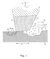
- a working surface 12 of a tool 10 is provided with tungsten carbide 14.
- the tool 10 is pressed by a force 16 against a substrate surface 20 to be treated.
- the tool 10 is moved with a velocity 18 over the substrate surface 20.
- a tribofilm 22 is created on the substrate surface 20.
- a tribofilm 22 is formed by tribochemical deposition.
- Tribofilms are often also referred to as wear transfer films, reaction layers etc.
- the substrate surface 20 is an iron-containing surface, e.g. a steel surface, which means that iron atoms 24 or particles are present at the substrate surface 20.
- a process fluid 30 comprising sulfur 32 in a free form is provided at or in vicinity of a contact area 8. Possible chemical reactions may comprise elements from the working surface 12 of the tool, from the substrate surface 20 and/or from the process fluid 30.
- a tribofilm 22 is formed comprising substances being or being similar to WS 2 26, i.e. a solid lubricant material.
- the substrate surface material also contributes to the chemical reaction forming a second phase 28, comprising FeS-like substances, since Fe is capable of forming stable sulfides.
- the formed tribofilm 22 in the model system thus has the solid lubricant 26 dispersed into a composite material, where the second phase 28 stems from the substrate material.
- This second phase 28 acts as a binder for the solid lubricant 26 onto the substrate surface 20.
- a WS 2 -containing film is formed by tribochemical deposition by a selective transfer of W from the W-containing working surface 12 to the substrate surface 20 and further chemical reaction with sulfur from the process fluid 30.
- the pressing force 16 is thus sufficient to generate a deformation of the material that leads to a chemical reaction between the tungsten, the sulfur and the substrate surface.
- the tribofilm 22 comprises virtually no carbon despite a high carbon content in the working surface 12 as well as in the process fluid 30.
- the formed tribofilm 22 fills up essentially all gaps and unevenness originally being present on the substrate surface 20.
- the WS 2 is typically bound to the substrate material by metal-sulfur bindings (as in iron sulfide, FeS).
- FeS iron sulfide
- the obtained surface of the tribofilm 22 becomes very smooth indeed, and a roughness down to below 10 nm is believed to be possible to produce within a near future.
- the smoothening operates by two mechanisms. First, the protruding edges of the substrate surface are cut by the physical action of the tool. Secondly, the formed tribofilm 22 fills up remaining valleys.
- the uniformity and efficiency of forming such a tribofilm 22 is greatly improved if the deposition is performed in more than one transverse direction, since edges and valleys then are affected in complementary manners. Furthermore, the use of more than one transverse direction in the sliding contact leads to a reduced tendency for void formation at the interface, this in turn leads to a enhanced coating adhesion.
- the thickness of the tribofilm 22 depends significantly on the original roughness of the substrate surface 20. A thicker tribofilm 22 can be achieved from a rough surface than from a smooth surface. Also, it has been concluded that the binding to the substrate is stronger for a tribofilm formed on a rough surface than a smooth surface. The final roughness of the formed tribofilm is, however, practically independent on the original substrate surface roughness.
- the original mean surface roughness (S a ) should be larger than 0.1 ⁇ m, preferably larger than 0.5 ⁇ m, more preferably larger than 1 ⁇ m and even more preferably larger than 2 ⁇ m.
- Mean surface roughness may be defined in different manners. However, in the present disclosure, numerical values of surface roughness are defined by the 3-dimensional obtained S a value being the arithmetic average roughness, also known as the centre-line average roughness.
- This surprising feature of the tribochemical deposition can advantageously be utilized in producing low-friction surfaces at different mechanical elements.
- the approach is particularly useful in preparing curved low-friction surfaces due to inherent problems with other alternative manufacturing processes being incompatible with curved surfaces.
- manufacturing of plane surfaces is also possible.
- the largest advantages are believed to appear when the curved surfaces are inner surfaces, e.g. an inner surface of a bearing bushing or the inner wall of a cylinder bore.
- Such bores can e.g. be cylinders of an internal combustion engine or cylinders of a hydraulic element.
- the present invention is also applicable on outer, convex, surfaces, such as e.g. shaft or piston surfaces. Rotationally symmetric surfaces are preferred since motions along rotationally symmetric surfaces are relatively easy to achieve.
- a cylinder of an engine element is used as a model mechanical element.
- FIG. 2 a typical prior art manufacturing process of a cylinder of an internal combustion engine is schematically illustrated.
- a cylinder bore 40 is provided in a mechanical element 41, in this example an engine element 42.
- a curved surface 43, having a rotationally symmetric geometry, in this example an inner surface 44 of the cylinder bore 40 typically has a rough surface.
- a rough honing is performed using e.g. a diamond stone, which provides the cylinder bore 40 with exactly the right dimensions.
- the inner surface is grinded to a finer surface roughness. The surface roughness is still too large for prior art applications, and a fine honing procedure is performed.
- a polishing stone is used to create a plateau finish.
- a diamond or a silicon carbide hone is typically used.
- the last step in this embodiment of a prior art process is to let the engine run to remove the last debris and smoothen the surface further. This part is often the most cumbersome since at least a part of the process typically takes place after e.g. the delivery of a vehicle. If the operation conditions are unfavourable, this running-in procedure may produce a cylinder bore surface far from ideal. The running-in step may also be omitted.
- Fig. 3 illustrates a corresponding manufacturing process according to the present invention.
- the boring step is basically unchanged.
- the rough honing step may be present, but not totally necessary. If the boring is accurate enough to provide the cylinder bore with the exact final dimensions, even the rough honing may be omitted.
- the fine honing and running-in steps are also omitted.
- a step of tribochemical deposition is performed in at least two transverse directions. A solid lubricant layer is thereby formed directly on the rough surface, giving a surface of low friction as well as a very small roughness.
- a typical value of the surface roughness achieved by an industrial application of the tribochemical deposition is estimated to be in the order of less than 0.1 ⁇ m.
- the final surface roughness is preferably less than 2/3 of a surface roughness of an original substrate surface, i.e. the surface onto which the tribochemical deposition is performed. From a comparison between Figs. 2 and 3 , one immediately realizes that the present invention makes it possible to completely remove at least two steps in the manufacturing process and replace them with a single step that gives a low friction surface coating as well as a low surface roughness. This new step can furthermore be performed without too large modifications of traditional manufacturing equipment, which means that the present invention is fairly cheep to implement also in existing manufacturing lines.
- a cylinder of an internal combustion engine having surfaces according to the present invention experience a lower friction than a conventional cylinder.
- Tests have shown that 6% of the total energy supplied to an internal combustion engine typically is lost due to friction from the piston ring and cylinder lining contact.
- Other tests, performed on surfaces manufactured according to the present invention show that boundary friction levels can be reduced by as much as 60 %. Such a reduction will therefore allow a total efficiency improvement of 1.8 to 3 %, reducing the fuel need.
- Estimations are made that during a lifetime of a cylinder, the savings in fuel may correspond to 5-10% of a total production cost of an entire vehicle.
- FIG. 4 The tribochemical deposition operation as obtained by a tool according to the present invention interacting with a surface is schematically illustrated in Fig. 4 .
- the substrate surface 20 before treatment has a surface roughness of at least 0.1 ⁇ m and preferably at least 0.5 ⁇ m.
- a process fluid 30 comprising sulfur is provided at the contact surroundings.
- a smooth tribofilm 22, comprising a solid lubricant, is resulting.
- the crystal planes of the solid lubricant will be directed essentially randomly.
- the actual tribochemical process introduces preferences in crystal plane directions.
- the tribochemical process favours the solid lubricant crystal planes to be directed essentially parallel to the surface. This in turn means that e.g. easily sheared sulfur-sulfur planes in the WS 2 crystal are parallel to the surface, which gives a significantly reduced friction even compared with randomly oriented WS 2 .
- a surface coated with WS 2 applied by tribochemical deposition therefore exhibits a lower friction than a surface coated with WS 2 applied in other ways.
- the sliding contact in the tribochemical process causes wear of the substrate surface peaks.
- parts of the "peaks" of the rough surfaces will be eroded and assist in filling up the "valleys" together with material from the working surface.
- a more efficient treatment is obtained if this wear also is directed in more than one direction in each point of at least a part of a surface to be treated.
- the building of the film becomes more even and results in a denser surface layer with improved adhesion.
- a motion of the tool along the substrate surface in at least two different directions that are transverse to each other, i.e. non-parallel to each other is more efficient.
- Empirical tests have been performed, comparing surfaces coated with WS 2 applied by tribochemical deposition in only one direction and surfaces coated with WS 2 applied by tribochemical deposition in transverse directions.
- the results show that surfaces coated in transverse directions present a smoother surface and a thicker layer of deposited WS 2 .
- the friction coefficient is also generally lower at the surfaces coated in transverse directions. The lower friction is believed to be the result of the smoother surface as well as better tribofilm coverage.
- the surface treatment in more than one direction also lowers the risk for transferring non-perfect geometries of the working surface to have any significant deteriorating impact on the final surface structure of the deposited film. For instance, if covering a circular cylinder surface, grooves texturing in the pure axial as well as in the pure tangential directions are only causing disadvantages. The same is true also for grooves having a pure spiral shape. However, by having the surfaces coated in transverse directions, any non-perfect geometries of the working surface will give rise to imperfections also distributed in transverse directions. Such patterns may assist in distributing e.g. additional fluid lubricants during the subsequent use.
- the relative direction of movement between the substrate surface and the tool will also influence the crystal directions.
- the direction, in which the tool has been moved, in the case of a one-dimensional motion, will generally exhibit a somewhat lower friction coefficient than in a direction perpendicular thereto.
- a shaft rotating within a bushing is known to have an essentially tangential relative motion. In such a case, it is preferable to have a majority of the working of the contact surfaces in a tangential direction, i.e.
- a piston is intended to be moved essentially axially with respect to the cylinder.
- the majority of the working of the contact surface is preferably performed in an axial direction, and a smaller part non-parallel thereto.
- Fig. 5 illustrates a flow diagram of steps of an embodiment of a manufacturing method according to the present invention.
- the manufacturing method begins in step 200.
- a mechanical element is provided with a surface to be covered.
- the surface may be curved, preferably rotationally symmetric, e.g. a cylinder bore surface.
- a cylinder bore can be an internal combustion engine cylinder bore, a turbine inner surface, a hydraulic cylinder bore or a sliding bearing cylinder surface. It may also be the outer surface of e.g. a shaft or a piston.
- the surface to be covered is rough grinded, giving the surface the requested dimensions.
- a surface roughness of more than S a 0.1 ⁇ m is to be preferred, and an even rougher surfaces up to at least the range of 2-3 ⁇ m are even more preferred due to the increased durability of the thicker coating.
- Step 212 may be omitted if e.g. step 210 directly provides the requested final dimensions and a suitable roughness.
- a solid lubricant substance is tribochemically deposited directly onto the surface in at least two transverse directions.
- the tribochemical deposition is preferably provided by pressing and sliding a tribochemical deposition tool working surface against the surface, causing deformation in a contact zone between the tribochemical deposition tool working surface and the surface to be covered.
- Step 214 preferably also comprises supplying of sulfur to the contact zone during the pressing and sliding action, whereby the sulfur reacts with the material that is wear transferred to the cylinder.
- any requested posttreatment of the covered surface e.g. a cylinder bore, may be performed, such as surface texturing methods or heat treatments. In a basic version of the method, however, step 216 may be omitted. The procedure ends in step 299.
- WS 2 has been used as a model solid lubricant as it comprises a layered crystal structure that is easily sheared.
- solid lubricants there are, however, also other candidates of solid lubricants to be used.
- Stable layered metal di-sulphides similar to WS 2 can be formed by metals as Ti, Nb, Mo and Sn.
- W and Mo are of particular interest.
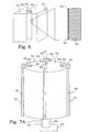
- FIG. 6 An embodiment of a mechanical element 41 manufactured by the method of Fig. 5 is schematically illustrated in Fig. 6 .
- a structure, in this embodiment a cylinder bore 40 is provided in a mechanical element 41, in this embodiment an engine element 42, giving a curved surface 43, in this embodiment an inner surface 44.
- the engine element 42 has a layer 22 of a tribochemically deposited solid lubricant substance. Since the original surface roughness was more than 0.1 ⁇ m, the surface layer 22 thickness typically exceeds 0.1 ⁇ m and the final surface roughness becomes far below 0.1 ⁇ m.
- FIG. 7A An embodiment of a tool 10 for manufacturing of a mechanical element having a curved surface is illustrated in Fig. 7A .
- the tool 10 is intended for processing of inner cylindrical surfaces.
- the tool 10 comprises a support portion 50, essentially formed by a cylindrical body 52 presenting a number of axially directed slits 54 distributed around the circumference of the cylindrical body 52.
- the cylindrical body is provided at a shaft 56.
- a tool holder 58 provided with a tool working surface 12, is arranged in each slit 54. (One tool holder is removed in the figure in order to increase the visibility of the front slit.)
- An elastic member 59 is provided in the slits 54 inside the tool holder.
- the elastic member 59 operates as a means 60 for providing a force pressing the tool working surface 12 outwards. Since the entire tool of this embodiment is intended to be put into a cylindrical hole for tribochemical deposition of the inside cylindrical surface, the tool working surface 12 is pressed towards that curved surface.
- the elastic member 59 could e.g. be a continuous beam of elastic material or an arrangement of springs.
- the means for providing a force pressing the tool working surface 12 towards the curved surface could be an active means, e.g. a mechanical arrangement that in a controlled manner provides a suitable pressing force, like compressed gases or hydraulic fluids.
- the tool 10 further comprises a driving means 61, in this embodiment operating on the shaft 56.
- the driving means 61 is arranged for moving the tool working surfaces in two different directions along the curved surface.
- the driving means 61 rotates the shaft 56 and also translates it in an axial direction.
- four working surfaces 12 are provided for.
- all four working surfaces 12 are intended to be working surfaces according to the description above. However, one or several of the working surfaces could be exchanged for purely mechanical working surfaces, only contributing with a general flattening operation, as complementary to the tribochemical working surfaces.
- FIG. 7B another embodiment of a tool 10 for manufacturing of a mechanical element having a curved surface is illustrated.
- the working surface 12 covers the cylindrical surface of a cylinder shaped tool holder 58, in turn supported by a support portion 50, in this embodiment having a general U-shape.
- the tool holder 58 is possible to rotate around its axis in order to present different parts of the surface in the front direction.
- the tool 10 in this embodiment is intended for treatment of an outer curved surface.
- the tool 10 is driven by a driving means 61 arranged to move the support portion 50 along a predetermined path.
- the elasticity of the support portion 50 and the tool holder 58 cooperates with the motion of the driving means 61 to create a force pressing the working surface 12 against the surface to be treated.
- the driving means 61 could easily be implemented by e.g. a CNC machine or an industrial robot.
- a tribochemically inert stone 69 is additionally attached to the support portion 50.
- the attachment part of the support portion is arranged as a means 68 for exchanging positions of the tribochemical deposition tool working surface and the tribochemically inert stone.
- the support portion 50 thereby becomes usable for both tribochemical deposition and other possible tribochemically inert treatments, such as rough honing, roughing-up of the surface before deposition or post-deposition compacting of the tribochemical surface.
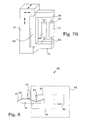
- FIG. 8 An embodiment of an apparatus 80 for manufacturing of a mechanical element having a curved surface is illustrated in Fig. 8 .
- a tool 10 is arranged to be pressed against and moved relative to a curved surface 20 of a mechanical element 41.
- a tribochemical surface layer 22 is thereby formed at the mechanical element 41.
- the apparatus 80 is in this embodiment provided with a contact resistance measuring means 82, comprising a control unit 84 electrically connected by connections 85, 86 to a measuring probe 83 and the mechanical element 41 respectively.
- the measuring probe 83 is a curved object with a radius smaller than the smallest radius of the curved surface of the mechanical element 41.
- the measurement probe 83 has a well defined surface and is brought into contact with the mechanical element in a well controlled manner.
- the control unit 84 is arranged to control the motion of the measuring probe 83.
- the control unit 84 is furthermore arranged to detect any changes in contact resistance.
- Such contact resistance measurement is known as such in prior art, but can applied in the present invention be used for controlling the working of the surface of the mechanical element 41 during the actual process.
- the contact resistance is largely influenced by the formation of the surface layer 22 and the working of the surface can thus be controlled until a requested contact resistance is achieved.
- the composition of the working surface of the tool has to provide the element capable of forming stable sulfides, e.g. a refractory metal, and in particular W and/or Mo, as a source for the tribochemical reaction. Suitable substances are to be found among oxides, carbides and silicides of these elements. Tool substances that are tested with good results are tungsten carbide, tungsten trioxide and molybdenum carbide.
- the working surface can be provided in different manners.
- a surface layer of the working surface substance can e.g. be deposited onto a tool core of another material, as e.g. indicated in Fig. 4 . Such depositions can be provided by e.g. PVD processes.
- the crystal size of the particles on the tool surface should be kept small for increased reactivity.
- a mean crystal size should be smaller than 100 nm.
- FIG. 9A an embodiment of a working stone usable with the present invention is illustrated.
- the working stone 90 comprises a cylindrical core 92. At the surface of the cylindrical core 92 a working surface 12 is deposited.
- the working stone 90 is during operation pressed against the surface to be treated and is simultaneously rotated. This has the advantage that the material of the working surface 12 will be worn at essentially the same rate all around the working stone 90.
- the actual shape of the working surface 12 is preferably adapted to the surface it is intended to treat. Treatment by a point contact between the working surface and the surface to be covered is possible, at least in theory. However, for practical purposes, extended contact areas or line contacts are preferred. In the embodiment of Fig. 9A , the contact area is typically a line contact.
- the working surface can therefore have different geometrical shapes. If the surfaces to be covered have small concave structures, the geometrical extension of the working surface has to be small. Here, a conformal contact area may be to prefer. In such embodiments, the contact area is an extended surface created when two mating surfaces fit exactly or even closely together. If instead a convex surface is to be treated, larger, and even plane or concave working surfaces can be used.
- conformal contact areas may be used.
- the working surface may also be plane.
- the total contact area has to be kept small enough to give a sufficient pressure in the contact zone. Line contacts are typically possible to use at all flat surfaces and surfaces being curved in one direction.
- FIG. 9B another embodiment of a working stone 90 is illustrated.
- the core 90 is covered by a working surface only at one narrow limited section.
- Such an embodiment has the advantage of being easy to attach to a tool, and no further motions have to be provided.
- surfaces having small concave curvature radii may be treated.
- the disadvantage is instead that the material of the working surface is very limited and the working stone 90 of this embodiment will quickly be worn out.
- a working stone 90 is illustrated.
- the core 90 is provided with a concave surface, with a working surface 12 deposited thereon.
- Such a working stone 90 is suitable e.g. for treating the outer surface of a shaft.
- FIG. 9D Another alternative is to provide a tool with a working stone, where the requested working surface substance exists throughout the entire volume of the working stone.
- a tool can be manufactured e.g. by binding grains of the oxide, carbide and/or silicide of Mo and/or W together by a binder substance. Suitable candidates can be found from metallic iron and carbon based synthetic adhesives.
- the working stone 90 could also exhibit small porous volumes 96, distributed all over the working surface, containing small amounts of necessary sulfur substances. The provision of the necessary sulfur can thus be achieved without need for any external supply.
Landscapes
- Chemical & Material Sciences (AREA)
- Engineering & Computer Science (AREA)
- Mechanical Engineering (AREA)
- Chemical Kinetics & Catalysis (AREA)
- Materials Engineering (AREA)
- Metallurgy (AREA)
- Organic Chemistry (AREA)
- Other Surface Treatments For Metallic Materials (AREA)
- Forging (AREA)
- Physical Vapour Deposition (AREA)
- Mounting, Exchange, And Manufacturing Of Dies (AREA)
Claims (15)
- Herstellverfahren für ein mechanisches Element (41), das folgenden Schritt aufweist:- Vorsehen (210) eines mechanischen Elements (41) mit einer zu beschichtenden Oberfläche (20),- gekennzeichnet durch einen weiteren Schritt:- tribochemisches Aufbringen (214) eines festen Schmierstoffes direkt auf der zu beschichtenden Oberfläche (20) im Beisein von Schwefel;- wobei das tribochemisches Aufbringen (214) in jedem Punkt von zumindest einem Teil der zu beschichtenden Oberfläche (20) in zumindest zwei Querrichtungen entlang der zu beschichtenden Oberfläche (20) ausgeführt wird;- wobei die Bewegung in zwei Querrichtungen an oder entlang einer Oberfläche durch zwei nicht parallele Bewegungen, die sich in einem Punkt auf der Oberfläche schneiden, definiert wird.
- Verfahren gemäß Anspruch 1, dadurch gekennzeichnet, dass der Schritt des tribochemischen Aufbringens (214) Folgendes aufweist:- Zusammendrücken und Gleitenlassen einer tribochemischen Aufbringungs-Werkzeugarbeitsfläche (12) auf der zu beschichtenden Oberfläche (20) in zumindest zwei Querrichtungen, die die Verformung in einem Kontaktbereich (8) zwischen der tribochemischen Aufbringungs-Werkzeugarbeitsfläche (12) und der zu beschichtenden Oberfläche (20) bewirken,- wobei die Abnutzungsübertragung des Materials von der tribochemischen Aufbringungs-Werkzeugarbeitsfläche (12) zur zu beschichtenden Oberfläche (20) bewirkt, dass eine gleichmäßige mechanische Elementfläche geschaffen wird.
- Verfahren gemäß Anspruch 2, dadurch gekennzeichnet, dass der Schritt des tribochemischen Aufbringens (214) ferner aufweist:- Zuführen des Schwefels zum Kontaktbereich (8) während des Zusammendrückens und Gleitenlassens,- wobei der Schwefel mit dem Material reagiert, das durch Verschleiß übertragen wird.
- Verfahren gemäß Anspruch 3, dadurch gekennzeichnet, dass das mechanische Element (41) an der zu beschichtenden Oberfläche (20) eine Substanz aufweist, die zum Bilden eines stabilen Sulfides geeignet ist.
- Verfahren gemäß Anspruch 4, dadurch gekennzeichnet, dass die Substanz, die zum Bilden eines stabilen Sulfides geeignet ist, Eisen (Fe) ist.
- Verfahren gemäß einem der Ansprüche 1 bis 5, dadurch gekennzeichnet, dass die zu beschichtende Oberfläche eine raue Oberfläche mit einer Oberflächenrauheit von mehr als Sa = 0,1 µm ist, wobei Sa als dreidimensionale arithmetische Durschnittsrauheit definiert ist, die auch als Mittenrauwert bekannt ist.
- Verfahren gemäß einem der Ansprüche 1 bis 6, dadurch gekennzeichnet, dass der feste Schmierstoff ein Sulfid mit zumindest entweder Molybdän oder Wolfram aufweist.
- Verfahren gemäß Anspruch 7, dadurch gekennzeichnet, dass die Werkzeugarbeitsfläche (12) zumindest entweder ein Oxid, Carbid oder Silicid mit zumindest entweder Molybdän oder Wolfram aufweist.
- Mechanisches Element (41) mit einer Oberfläche mit niedrigem Reibwert, dadurch gekennzeichnet, dass die Oberfläche (20) mit niedrigem Reibwert eine Oberflächenschicht (22) eines tribochemisch aufgebrachten festen Schmierstoffs aufweist, der in jedem Punkt von zumindest einem Teil der Oberfläche (20) mit niedrigem Reibwert in zumindest zwei Querrichtungen entlang der Oberfläche (20) mit niedrigem Reibwert im Beisein von Schwefel aufgebracht wird, wobei die Bewegung in zwei Querrichtungen an oder entlang einer Oberfläche durch zwei nicht parallele Bewegungen, die sich in einem Punkt auf der Oberfläche schneiden, definiert ist.
- Mechanisches Element gemäß Anspruch 9, dadurch gekennzeichnet, dass der feste Schmierstoff ein Sulfid mit zumindest entweder Molybdän oder Wolfram aufweist.
- Mechanisches Element gemäß Anspruch 9 oder 10, dadurch gekennzeichnet, dass die Oberfläche (20) mit niedrigem Reibwert eine gekrümmte Oberfläche (43) ist.
- Werkzeug (10) zum Herstellen eines mechanischen Elements (41), das eine Oberfläche (20) mit niedrigem Reibwert aufweist:- mit einem Abstützbereich (50);- mit zumindest einer Werkzeugarbeitsfläche (12); und- mit einem Mittel (60) zum Vorsehen einer Kraft, die zumindest eine Werkzeugarbeitsfläche (12) in Richtung einer Oberfläche (20) des zu beschichtenden mechanischen Elements (41) drückt;- wobei zumindest eine Werkzeugarbeitsfläche (12) eine tribochemische Aufbringungs-Werkzeugarbeitsfläche ist, die zumindest entweder ein Oxid, Carbid oder Silicid mit einem Element aufweist, das zum Bilden eines stabilen geschichteten Metall-Di-Sulfids geeignet ist,- ferner gekennzeichnet durch Antriebsmittel (61) zum Bewegen von zumindest einer tribochemischen Aufbringungs-Werkzeugarbeitsfläche in zumindest zwei Querrichtungen bezüglich der Oberfläche (20) des mechanischen Elements (41), das an jedem Punkt von zumindest einem Teil der Oberfläche (20) zu beschichten ist:- wobei die Bewegung in zwei Querrichtungen an oder entlang einer Oberfläche durch zwei nicht parallele Bewegungen, die sich in einem Punkt auf der Oberfläche schneiden, definiert wird.
- Werkzeug gemäß Anspruch 12, dadurch gekennzeichnet, dass die tribochemische Aufbringungs-Werkzeugarbeitsfläche zumindest entweder ein Oxid, Carbid oder Silicid mit zumindest entweder Molybdän oder Wolfram aufweist.
- Werkzeug gemäß Anspruch 12 oder 13, dadurch gekennzeichnet, dass die tribochemische Aufbringungs-Werkzeugarbeitsfläche (12) ein Bindemittel aufweist, das die Körner von zumindest entweder einem Oxid, Carbid oder Silicid bindet.
- Werkzeug gemäß einem der Ansprüche 12 bis 14, dadurch gekennzeichnet, dass die tribochemische Aufbringungs-Werkzeugarbeitsfläche poröse Volumen (96) mit Schwefel aufweist.
Priority Applications (1)
| Application Number | Priority Date | Filing Date | Title |
|---|---|---|---|
| PL08857238T PL2229467T3 (pl) | 2007-12-07 | 2008-12-05 | Wytwarzanie elementów o małym tarciu |
Applications Claiming Priority (2)
| Application Number | Priority Date | Filing Date | Title |
|---|---|---|---|
| SE0702751 | 2007-12-07 | ||
| PCT/EP2008/066909 WO2009071674A2 (en) | 2007-12-07 | 2008-12-05 | Manufacturing of low-friction elements |
Publications (2)
| Publication Number | Publication Date |
|---|---|
| EP2229467A2 EP2229467A2 (de) | 2010-09-22 |
| EP2229467B1 true EP2229467B1 (de) | 2012-06-06 |
Family
ID=40602203
Family Applications (1)
| Application Number | Title | Priority Date | Filing Date |
|---|---|---|---|
| EP20080857238 Active EP2229467B1 (de) | 2007-12-07 | 2008-12-05 | Herstellung von elementen mit geringer reibung |
Country Status (12)
| Country | Link |
|---|---|
| US (1) | US8545930B2 (de) |
| EP (1) | EP2229467B1 (de) |
| JP (1) | JP5761783B2 (de) |
| KR (1) | KR101597817B1 (de) |
| CN (1) | CN101918612B (de) |
| BR (1) | BRPI0820928B1 (de) |
| CA (1) | CA2704078C (de) |
| EA (1) | EA017903B1 (de) |
| ES (1) | ES2391362T3 (de) |
| MX (1) | MX2010005608A (de) |
| PL (1) | PL2229467T3 (de) |
| WO (1) | WO2009071674A2 (de) |
Cited By (1)
| Publication number | Priority date | Publication date | Assignee | Title |
|---|---|---|---|---|
| DE102015212754A1 (de) * | 2015-07-08 | 2017-01-12 | Volkswagen Aktiengesellschaft | Verfahren zur tribologischen Konditionierung eines Oberflächenbereichs eines Werkstücks |
Families Citing this family (21)
| Publication number | Priority date | Publication date | Assignee | Title |
|---|---|---|---|---|
| JP5435734B2 (ja) * | 2010-05-27 | 2014-03-05 | 富士フイルム株式会社 | 鏡枠部品、レンズ組立体、撮像装置、および鏡枠部品の製造方法 |
| MX335107B (es) | 2010-07-16 | 2015-11-26 | Applied Nano Surfaces Sweden Ab | Metodo para proveer una superficie de baja friccion. |
| US8641479B2 (en) | 2010-09-01 | 2014-02-04 | Ford Motor Company | Tool assembly for machining a bore |
| DE102010048550A1 (de) * | 2010-10-14 | 2012-04-19 | Man Truck & Bus Ag | Verfahren zur Bearbeitung, insbesondere zur mechanischen Bearbeitung, wenigstens eines abgasführenden Oberflächenbereichs eines Brennkraftmaschinen- oder Kurbelgehäusebestandteils sowie Brennkraftmaschinen-Kurbelgehäuse und Zylinderlaufbuchse |
| DE102011114420A1 (de) * | 2011-09-26 | 2013-03-28 | Audi Ag | Verfahren zum Herstellen eines Zylinderrohrs einer Brennkraftmaschine sowie entsprechendes Zylinderrohr |
| JP2013085913A (ja) * | 2011-10-22 | 2013-05-13 | San Medical Gijutsu Kenkyusho:Kk | 摺動装置、メカニカルシール、回転装置、ポンプ及び補助人工心臓システム |
| EP2782986A1 (de) * | 2011-11-23 | 2014-10-01 | ABB Research Ltd. | Dichtungssystem, industrieroboter mit dichtungssystem und verfahren zur bereitstellung einer dichtfläche |
| CN104160065B (zh) * | 2011-12-13 | 2016-05-11 | Skf公司 | 在机械组件的摩擦面上制备保护层的方法 |
| BR102012012636B1 (pt) * | 2012-05-25 | 2022-01-04 | Mahle Metal Leve S/A | Cilindro para aplicação em um motor de combustão interna |
| US9133739B2 (en) | 2012-05-30 | 2015-09-15 | GM Global Technology Operations LLC | Method for in-situ forming of low friction coatings on engine cylinder bores |
| US8476206B1 (en) * | 2012-07-02 | 2013-07-02 | Ajay P. Malshe | Nanoparticle macro-compositions |
| WO2014138829A1 (en) | 2013-03-14 | 2014-09-18 | Mahle Metal Leve S/A | Sliding set for use in an international combustion engine |
| US9476007B2 (en) | 2013-09-26 | 2016-10-25 | Uchicago Argonne, Llc | Tribological synthesis method for producing low-friction surface film coating |
| BR102013030435A2 (pt) | 2013-11-27 | 2015-07-07 | Mahle Metal Leve Sa | Método para condicionamento tribomecânico de um cilindro/camisa de paredes finas, e cilindro/camisa |
| SE538554C2 (en) * | 2014-12-05 | 2016-09-20 | Applied Nano Surfaces Sweden Ab | Mechanochemical conditioning tool |
| US20160280293A1 (en) | 2015-03-24 | 2016-09-29 | Caterpillar Inc. | Break-In Coating on Track Assembly Components |
| CN106180770A (zh) * | 2015-04-17 | 2016-12-07 | 上海睿锆信息科技有限公司 | 工件及其在切削加工中的应用 |
| RU2591932C1 (ru) * | 2015-06-10 | 2016-07-20 | Федеральное государственное унитарное предприятие "Всероссийский научно-исследовательский институт авиационных материалов" (ФГУП "ВИАМ") | Способ получения износостойкого покрытия |
| US10768202B2 (en) * | 2015-09-08 | 2020-09-08 | The Trustees Of The University Of Pennsylvania | Systems and methods for nano-tribological manufacturing of nanostructures |
| US11208907B2 (en) | 2017-07-13 | 2021-12-28 | Raytheon Technologies Corporation | Seals and methods of making seals |
| FR3072689B1 (fr) * | 2017-10-23 | 2021-10-01 | Univ Des Antilles | Systeme et procede de formation d'un film mince lubrifiant solide sur une piece mecanique |
Family Cites Families (9)
| Publication number | Priority date | Publication date | Assignee | Title |
|---|---|---|---|---|
| GB847800A (en) | 1956-01-04 | 1960-09-14 | Alpha Molykote Corp | Method for forming metal sulfide coatings |
| JPS55100422A (en) * | 1979-01-25 | 1980-07-31 | Koyo Seiko Co Ltd | Self-lubricant ball bearing |
| US5302450A (en) | 1993-07-06 | 1994-04-12 | Ford Motor Company | Metal encapsulated solid lubricant coating system |
| JP4104778B2 (ja) * | 1999-04-28 | 2008-06-18 | 剛 篠田 | 円柱内面のコーティング方法 |
| KR100391307B1 (ko) * | 2001-06-04 | 2003-07-16 | 한라공조주식회사 | 고체 윤활 피막 형성방법 |
| CN1142320C (zh) | 2001-07-18 | 2004-03-17 | 浙江大学 | 含有无机类富勒烯结构的纳米材料的复合镀层及制备方法 |
| JP2004076914A (ja) | 2002-08-22 | 2004-03-11 | Toyota Motor Corp | 被膜及び該被膜が形成された摺動部材 |
| US8323349B2 (en) * | 2004-02-17 | 2012-12-04 | The University Of Notre Dame Du Lac | Textured surfaces for orthopedic implants |
| JP4688161B2 (ja) * | 2006-03-30 | 2011-05-25 | 大同メタル工業株式会社 | 摺動部材およびその被覆層形成方法 |
-
2008
- 2008-12-05 BR BRPI0820928-6A patent/BRPI0820928B1/pt not_active IP Right Cessation
- 2008-12-05 WO PCT/EP2008/066909 patent/WO2009071674A2/en not_active Ceased
- 2008-12-05 US US12/746,215 patent/US8545930B2/en not_active Expired - Fee Related
- 2008-12-05 MX MX2010005608A patent/MX2010005608A/es active IP Right Grant
- 2008-12-05 CA CA2704078A patent/CA2704078C/en not_active Expired - Fee Related
- 2008-12-05 EP EP20080857238 patent/EP2229467B1/de active Active
- 2008-12-05 PL PL08857238T patent/PL2229467T3/pl unknown
- 2008-12-05 EA EA201000925A patent/EA017903B1/ru not_active IP Right Cessation
- 2008-12-05 JP JP2010536475A patent/JP5761783B2/ja active Active
- 2008-12-05 KR KR1020107013820A patent/KR101597817B1/ko not_active Expired - Fee Related
- 2008-12-05 ES ES08857238T patent/ES2391362T3/es active Active
- 2008-12-05 CN CN2008801194740A patent/CN101918612B/zh not_active Expired - Fee Related
Cited By (2)
| Publication number | Priority date | Publication date | Assignee | Title |
|---|---|---|---|---|
| DE102015212754A1 (de) * | 2015-07-08 | 2017-01-12 | Volkswagen Aktiengesellschaft | Verfahren zur tribologischen Konditionierung eines Oberflächenbereichs eines Werkstücks |
| DE102015212754B4 (de) * | 2015-07-08 | 2024-03-21 | Volkswagen Aktiengesellschaft | Verfahren zur tribologischen Konditionierung eines Oberflächenbereichs eines Werkstücks und entsprechende Verwendung eines Bearbeitungswerkzeugs |
Also Published As
| Publication number | Publication date |
|---|---|
| CN101918612A (zh) | 2010-12-15 |
| EP2229467A2 (de) | 2010-09-22 |
| US8545930B2 (en) | 2013-10-01 |
| EA017903B1 (ru) | 2013-04-30 |
| CA2704078A1 (en) | 2009-06-11 |
| BRPI0820928B1 (pt) | 2019-04-09 |
| US20100272931A1 (en) | 2010-10-28 |
| ES2391362T3 (es) | 2012-11-23 |
| WO2009071674A2 (en) | 2009-06-11 |
| EA201000925A1 (ru) | 2010-12-30 |
| CN101918612B (zh) | 2012-11-14 |
| MX2010005608A (es) | 2010-08-31 |
| BRPI0820928A2 (pt) | 2015-06-23 |
| KR101597817B1 (ko) | 2016-03-02 |
| CA2704078C (en) | 2017-05-16 |
| JP5761783B2 (ja) | 2015-08-12 |
| PL2229467T3 (pl) | 2012-11-30 |
| KR20100102617A (ko) | 2010-09-24 |
| JP2011506760A (ja) | 2011-03-03 |
| WO2009071674A3 (en) | 2009-09-24 |
Similar Documents
| Publication | Publication Date | Title |
|---|---|---|
| EP2229467B1 (de) | Herstellung von elementen mit geringer reibung | |
| Jianxin et al. | Performance of carbide tools with textured rake-face filled with solid lubricants in dry cutting processes | |
| EP0707622B1 (de) | BESCHICHTUNGSSYSTEM AUS WäRMEHäRTBAREM POLYMER UND FESTSCHMIERSTOFF | |
| KR100306922B1 (ko) | 실린더라이너및그제조방법 | |
| JP5669390B2 (ja) | 耐摩耗性コーティングならびにこのための製造法 | |
| CN103097578B (zh) | 用于提供低摩擦表面的方法 | |
| Singh et al. | High temperature friction and wear of atmospheric plasma spray deposited NiMoAl-Ag-WS2 composite coatings | |
| EP3394457B1 (de) | Beschichtung eines systems und verfahren dazu | |
| KR20140034142A (ko) | 고체 윤활제 입자의 분산물을 갖는 용사 코팅 | |
| CA2565190A1 (en) | Method for applying a low coefficient of friction coating | |
| JP2009293128A (ja) | 高強度鋼製機械部品の表面処理方法、および前記方法の実施によって得られるシーリングシステム | |
| US20180245638A1 (en) | Method for coating a component | |
| US20220145934A1 (en) | Diamond surface bearings for sliding engagement with metal surfaces | |
| US5955145A (en) | Process for forming a wear-resistant coating that minimizes debris | |
| CN104160065A (zh) | 在机械组件的摩擦面上制备保护层的方法 | |
| WO2013075739A1 (en) | A sealing system, an industrial robot with a sealing system, and a method for providing a sealing surface | |
| Zhmud et al. | Mastering the Art of cylinder bore honing | |
| Rausch et al. | Five-axis grinding of wear-resistant, thermally sprayed coatings on free-formed surfaces | |
| WO1999047290A1 (en) | Rolling die and method of treating surface of rolling die | |
| Lee | ea ans-e-a flea aes—eazni we a 11} ea visas— | |
| Narayanasamy et al. | 335 Production of surface texture in Extrude honing |
Legal Events
| Date | Code | Title | Description |
|---|---|---|---|
| PUAI | Public reference made under article 153(3) epc to a published international application that has entered the european phase |
Free format text: ORIGINAL CODE: 0009012 |
|
| 17P | Request for examination filed |
Effective date: 20100707 |
|
| AK | Designated contracting states |
Kind code of ref document: A2 Designated state(s): AT BE BG CH CY CZ DE DK EE ES FI FR GB GR HR HU IE IS IT LI LT LU LV MC MT NL NO PL PT RO SE SI SK TR |
|
| AX | Request for extension of the european patent |
Extension state: AL BA MK RS |
|
| DAX | Request for extension of the european patent (deleted) | ||
| 17Q | First examination report despatched |
Effective date: 20110428 |
|
| GRAP | Despatch of communication of intention to grant a patent |
Free format text: ORIGINAL CODE: EPIDOSNIGR1 |
|
| GRAS | Grant fee paid |
Free format text: ORIGINAL CODE: EPIDOSNIGR3 |
|
| GRAA | (expected) grant |
Free format text: ORIGINAL CODE: 0009210 |
|
| AK | Designated contracting states |
Kind code of ref document: B1 Designated state(s): AT BE BG CH CY CZ DE DK EE ES FI FR GB GR HR HU IE IS IT LI LT LU LV MC MT NL NO PL PT RO SE SI SK TR |
|
| REG | Reference to a national code |
Ref country code: GB Ref legal event code: FG4D |
|
| REG | Reference to a national code |
Ref country code: AT Ref legal event code: REF Ref document number: 561093 Country of ref document: AT Kind code of ref document: T Effective date: 20120615 Ref country code: CH Ref legal event code: EP |
|
| REG | Reference to a national code |
Ref country code: IE Ref legal event code: FG4D |
|
| REG | Reference to a national code |
Ref country code: DE Ref legal event code: R096 Ref document number: 602008016242 Country of ref document: DE Effective date: 20120802 |
|
| REG | Reference to a national code |
Ref country code: SE Ref legal event code: TRGR |
|
| REG | Reference to a national code |
Ref country code: NL Ref legal event code: T3 |
|
| REG | Reference to a national code |
Ref country code: CH Ref legal event code: NV Representative=s name: R. A. EGLI & CO. PATENTANWAELTE |
|
| PG25 | Lapsed in a contracting state [announced via postgrant information from national office to epo] |
Ref country code: NO Free format text: LAPSE BECAUSE OF FAILURE TO SUBMIT A TRANSLATION OF THE DESCRIPTION OR TO PAY THE FEE WITHIN THE PRESCRIBED TIME-LIMIT Effective date: 20120906 Ref country code: LT Free format text: LAPSE BECAUSE OF FAILURE TO SUBMIT A TRANSLATION OF THE DESCRIPTION OR TO PAY THE FEE WITHIN THE PRESCRIBED TIME-LIMIT Effective date: 20120606 Ref country code: CY Free format text: LAPSE BECAUSE OF FAILURE TO SUBMIT A TRANSLATION OF THE DESCRIPTION OR TO PAY THE FEE WITHIN THE PRESCRIBED TIME-LIMIT Effective date: 20120606 Ref country code: FI Free format text: LAPSE BECAUSE OF FAILURE TO SUBMIT A TRANSLATION OF THE DESCRIPTION OR TO PAY THE FEE WITHIN THE PRESCRIBED TIME-LIMIT Effective date: 20120606 |
|
| REG | Reference to a national code |
Ref country code: ES Ref legal event code: FG2A Ref document number: 2391362 Country of ref document: ES Kind code of ref document: T3 Effective date: 20121123 |
|
| REG | Reference to a national code |
Ref country code: LT Ref legal event code: MG4D Effective date: 20120606 |
|
| PG25 | Lapsed in a contracting state [announced via postgrant information from national office to epo] |
Ref country code: HR Free format text: LAPSE BECAUSE OF FAILURE TO SUBMIT A TRANSLATION OF THE DESCRIPTION OR TO PAY THE FEE WITHIN THE PRESCRIBED TIME-LIMIT Effective date: 20120606 Ref country code: LV Free format text: LAPSE BECAUSE OF FAILURE TO SUBMIT A TRANSLATION OF THE DESCRIPTION OR TO PAY THE FEE WITHIN THE PRESCRIBED TIME-LIMIT Effective date: 20120606 Ref country code: SI Free format text: LAPSE BECAUSE OF FAILURE TO SUBMIT A TRANSLATION OF THE DESCRIPTION OR TO PAY THE FEE WITHIN THE PRESCRIBED TIME-LIMIT Effective date: 20120606 Ref country code: GR Free format text: LAPSE BECAUSE OF FAILURE TO SUBMIT A TRANSLATION OF THE DESCRIPTION OR TO PAY THE FEE WITHIN THE PRESCRIBED TIME-LIMIT Effective date: 20120907 |
|
| REG | Reference to a national code |
Ref country code: PL Ref legal event code: T3 |
|
| PG25 | Lapsed in a contracting state [announced via postgrant information from national office to epo] |
Ref country code: SK Free format text: LAPSE BECAUSE OF FAILURE TO SUBMIT A TRANSLATION OF THE DESCRIPTION OR TO PAY THE FEE WITHIN THE PRESCRIBED TIME-LIMIT Effective date: 20120606 Ref country code: BE Free format text: LAPSE BECAUSE OF FAILURE TO SUBMIT A TRANSLATION OF THE DESCRIPTION OR TO PAY THE FEE WITHIN THE PRESCRIBED TIME-LIMIT Effective date: 20120606 Ref country code: CZ Free format text: LAPSE BECAUSE OF FAILURE TO SUBMIT A TRANSLATION OF THE DESCRIPTION OR TO PAY THE FEE WITHIN THE PRESCRIBED TIME-LIMIT Effective date: 20120606 Ref country code: EE Free format text: LAPSE BECAUSE OF FAILURE TO SUBMIT A TRANSLATION OF THE DESCRIPTION OR TO PAY THE FEE WITHIN THE PRESCRIBED TIME-LIMIT Effective date: 20120606 Ref country code: RO Free format text: LAPSE BECAUSE OF FAILURE TO SUBMIT A TRANSLATION OF THE DESCRIPTION OR TO PAY THE FEE WITHIN THE PRESCRIBED TIME-LIMIT Effective date: 20120606 Ref country code: IS Free format text: LAPSE BECAUSE OF FAILURE TO SUBMIT A TRANSLATION OF THE DESCRIPTION OR TO PAY THE FEE WITHIN THE PRESCRIBED TIME-LIMIT Effective date: 20121006 |
|
| PG25 | Lapsed in a contracting state [announced via postgrant information from national office to epo] |
Ref country code: PT Free format text: LAPSE BECAUSE OF FAILURE TO SUBMIT A TRANSLATION OF THE DESCRIPTION OR TO PAY THE FEE WITHIN THE PRESCRIBED TIME-LIMIT Effective date: 20121008 |
|
| PLBE | No opposition filed within time limit |
Free format text: ORIGINAL CODE: 0009261 |
|
| STAA | Information on the status of an ep patent application or granted ep patent |
Free format text: STATUS: NO OPPOSITION FILED WITHIN TIME LIMIT |
|
| PG25 | Lapsed in a contracting state [announced via postgrant information from national office to epo] |
Ref country code: DK Free format text: LAPSE BECAUSE OF FAILURE TO SUBMIT A TRANSLATION OF THE DESCRIPTION OR TO PAY THE FEE WITHIN THE PRESCRIBED TIME-LIMIT Effective date: 20120606 |
|
| 26N | No opposition filed |
Effective date: 20130307 |
|
| REG | Reference to a national code |
Ref country code: DE Ref legal event code: R097 Ref document number: 602008016242 Country of ref document: DE Effective date: 20130307 |
|
| PG25 | Lapsed in a contracting state [announced via postgrant information from national office to epo] |
Ref country code: BG Free format text: LAPSE BECAUSE OF FAILURE TO SUBMIT A TRANSLATION OF THE DESCRIPTION OR TO PAY THE FEE WITHIN THE PRESCRIBED TIME-LIMIT Effective date: 20120906 Ref country code: MC Free format text: LAPSE BECAUSE OF NON-PAYMENT OF DUE FEES Effective date: 20121231 |
|
| REG | Reference to a national code |
Ref country code: IE Ref legal event code: MM4A |
|
| PG25 | Lapsed in a contracting state [announced via postgrant information from national office to epo] |
Ref country code: IE Free format text: LAPSE BECAUSE OF NON-PAYMENT OF DUE FEES Effective date: 20121205 |
|
| PG25 | Lapsed in a contracting state [announced via postgrant information from national office to epo] |
Ref country code: MT Free format text: LAPSE BECAUSE OF FAILURE TO SUBMIT A TRANSLATION OF THE DESCRIPTION OR TO PAY THE FEE WITHIN THE PRESCRIBED TIME-LIMIT Effective date: 20120606 |
|
| PG25 | Lapsed in a contracting state [announced via postgrant information from national office to epo] |
Ref country code: LU Free format text: LAPSE BECAUSE OF NON-PAYMENT OF DUE FEES Effective date: 20121205 |
|
| PG25 | Lapsed in a contracting state [announced via postgrant information from national office to epo] |
Ref country code: HU Free format text: LAPSE BECAUSE OF FAILURE TO SUBMIT A TRANSLATION OF THE DESCRIPTION OR TO PAY THE FEE WITHIN THE PRESCRIBED TIME-LIMIT Effective date: 20081205 |
|
| REG | Reference to a national code |
Ref country code: FR Ref legal event code: PLFP Year of fee payment: 8 |
|
| REG | Reference to a national code |
Ref country code: FR Ref legal event code: PLFP Year of fee payment: 9 |
|
| REG | Reference to a national code |
Ref country code: FR Ref legal event code: PLFP Year of fee payment: 10 |
|
| PGFP | Annual fee paid to national office [announced via postgrant information from national office to epo] |
Ref country code: NL Payment date: 20191129 Year of fee payment: 12 |
|
| PGFP | Annual fee paid to national office [announced via postgrant information from national office to epo] |
Ref country code: PL Payment date: 20191127 Year of fee payment: 12 |
|
| PGFP | Annual fee paid to national office [announced via postgrant information from national office to epo] |
Ref country code: TR Payment date: 20191128 Year of fee payment: 12 Ref country code: AT Payment date: 20191128 Year of fee payment: 12 Ref country code: CH Payment date: 20191129 Year of fee payment: 12 |
|
| PGFP | Annual fee paid to national office [announced via postgrant information from national office to epo] |
Ref country code: ES Payment date: 20200120 Year of fee payment: 12 |
|
| REG | Reference to a national code |
Ref country code: CH Ref legal event code: PL |
|
| REG | Reference to a national code |
Ref country code: NL Ref legal event code: MM Effective date: 20210101 |
|
| REG | Reference to a national code |
Ref country code: AT Ref legal event code: MM01 Ref document number: 561093 Country of ref document: AT Kind code of ref document: T Effective date: 20201205 |
|
| PG25 | Lapsed in a contracting state [announced via postgrant information from national office to epo] |
Ref country code: NL Free format text: LAPSE BECAUSE OF NON-PAYMENT OF DUE FEES Effective date: 20210101 |
|
| PG25 | Lapsed in a contracting state [announced via postgrant information from national office to epo] |
Ref country code: AT Free format text: LAPSE BECAUSE OF NON-PAYMENT OF DUE FEES Effective date: 20201205 |
|
| PG25 | Lapsed in a contracting state [announced via postgrant information from national office to epo] |
Ref country code: LI Free format text: LAPSE BECAUSE OF NON-PAYMENT OF DUE FEES Effective date: 20201231 Ref country code: CH Free format text: LAPSE BECAUSE OF NON-PAYMENT OF DUE FEES Effective date: 20201231 |
|
| PGFP | Annual fee paid to national office [announced via postgrant information from national office to epo] |
Ref country code: GB Payment date: 20211215 Year of fee payment: 14 Ref country code: FR Payment date: 20211216 Year of fee payment: 14 |
|
| REG | Reference to a national code |
Ref country code: ES Ref legal event code: FD2A Effective date: 20220208 |
|
| PGFP | Annual fee paid to national office [announced via postgrant information from national office to epo] |
Ref country code: IT Payment date: 20211220 Year of fee payment: 14 |
|
| PG25 | Lapsed in a contracting state [announced via postgrant information from national office to epo] |
Ref country code: ES Free format text: LAPSE BECAUSE OF NON-PAYMENT OF DUE FEES Effective date: 20201206 |
|
| PG25 | Lapsed in a contracting state [announced via postgrant information from national office to epo] |
Ref country code: TR Free format text: LAPSE BECAUSE OF NON-PAYMENT OF DUE FEES Effective date: 20201205 |
|
| PG25 | Lapsed in a contracting state [announced via postgrant information from national office to epo] |
Ref country code: PL Free format text: LAPSE BECAUSE OF NON-PAYMENT OF DUE FEES Effective date: 20201205 |
|
| GBPC | Gb: european patent ceased through non-payment of renewal fee |
Effective date: 20221205 |
|
| REG | Reference to a national code |
Ref country code: DE Ref legal event code: R081 Ref document number: 602008016242 Country of ref document: DE Owner name: TRIBONEX AB, SE Free format text: FORMER OWNER: APPLIED NANO SURFACES SWEDEN AB, STOCKHOLM, SE |
|
| PG25 | Lapsed in a contracting state [announced via postgrant information from national office to epo] |
Ref country code: GB Free format text: LAPSE BECAUSE OF NON-PAYMENT OF DUE FEES Effective date: 20221205 |
|
| PG25 | Lapsed in a contracting state [announced via postgrant information from national office to epo] |
Ref country code: FR Free format text: LAPSE BECAUSE OF NON-PAYMENT OF DUE FEES Effective date: 20221231 |
|
| PG25 | Lapsed in a contracting state [announced via postgrant information from national office to epo] |
Ref country code: IT Free format text: LAPSE BECAUSE OF NON-PAYMENT OF DUE FEES Effective date: 20221205 |
|
| PGFP | Annual fee paid to national office [announced via postgrant information from national office to epo] |
Ref country code: DE Payment date: 20241218 Year of fee payment: 17 |
|
| PGFP | Annual fee paid to national office [announced via postgrant information from national office to epo] |
Ref country code: SE Payment date: 20241217 Year of fee payment: 17 |