EP2227414B1 - Vorrichtung zur werkzeuglosen höhenverstellung einer baugruppe - Google Patents
Vorrichtung zur werkzeuglosen höhenverstellung einer baugruppe Download PDFInfo
- Publication number
- EP2227414B1 EP2227414B1 EP08803188A EP08803188A EP2227414B1 EP 2227414 B1 EP2227414 B1 EP 2227414B1 EP 08803188 A EP08803188 A EP 08803188A EP 08803188 A EP08803188 A EP 08803188A EP 2227414 B1 EP2227414 B1 EP 2227414B1
- Authority
- EP
- European Patent Office
- Prior art keywords
- base plate
- toothing
- wedge
- height adjustment
- support
- Prior art date
- Legal status (The legal status is an assumption and is not a legal conclusion. Google has not performed a legal analysis and makes no representation as to the accuracy of the status listed.)
- Not-in-force
Links
- 238000006073 displacement reaction Methods 0.000 claims abstract description 10
- 239000002245 particle Substances 0.000 claims description 2
- 230000035515 penetration Effects 0.000 claims 1
- 230000000712 assembly Effects 0.000 abstract description 4
- 238000000429 assembly Methods 0.000 abstract description 4
- 238000000034 method Methods 0.000 description 5
- 230000000694 effects Effects 0.000 description 2
- 238000009434 installation Methods 0.000 description 2
- 239000000463 material Substances 0.000 description 2
- 229910000838 Al alloy Inorganic materials 0.000 description 1
- 230000006835 compression Effects 0.000 description 1
- 238000007906 compression Methods 0.000 description 1
- 238000005520 cutting process Methods 0.000 description 1
- 230000000994 depressogenic effect Effects 0.000 description 1
- 210000003746 feather Anatomy 0.000 description 1
- 238000004519 manufacturing process Methods 0.000 description 1
- 238000003825 pressing Methods 0.000 description 1
- 239000011343 solid material Substances 0.000 description 1
- 238000003860 storage Methods 0.000 description 1
- 239000013589 supplement Substances 0.000 description 1
Images


Classifications
-
- B—PERFORMING OPERATIONS; TRANSPORTING
- B64—AIRCRAFT; AVIATION; COSMONAUTICS
- B64D—EQUIPMENT FOR FITTING IN OR TO AIRCRAFT; FLIGHT SUITS; PARACHUTES; ARRANGEMENT OR MOUNTING OF POWER PLANTS OR PROPULSION TRANSMISSIONS IN AIRCRAFT
- B64D11/00—Passenger or crew accommodation; Flight-deck installations not otherwise provided for
- B64D11/04—Galleys
-
- F—MECHANICAL ENGINEERING; LIGHTING; HEATING; WEAPONS; BLASTING
- F16—ENGINEERING ELEMENTS AND UNITS; GENERAL MEASURES FOR PRODUCING AND MAINTAINING EFFECTIVE FUNCTIONING OF MACHINES OR INSTALLATIONS; THERMAL INSULATION IN GENERAL
- F16M—FRAMES, CASINGS OR BEDS OF ENGINES, MACHINES OR APPARATUS, NOT SPECIFIC TO ENGINES, MACHINES OR APPARATUS PROVIDED FOR ELSEWHERE; STANDS; SUPPORTS
- F16M7/00—Details of attaching or adjusting engine beds, frames, or supporting-legs on foundation or base; Attaching non-moving engine parts, e.g. cylinder blocks
Definitions
- the invention relates to a device with a base plate and a support for tool-free height adjustment of an assembly, in particular a kitchen module in an aircraft.
- US 5,427,349 A discloses a device for height adjustment with the features of the preamble of claim 1.
- the object of the invention is to provide a device for height adjustment of assemblies in aircraft, which allows a fast and tool-free and substantially continuous height adjustment of the assembly when installed in a fuselage structure of an aircraft without losing parts.
- the respectively set horizontal position of the wedge body is prevented by securing means, so that uncontrolled shifts and thus a change in height of the device are excluded.
- an upper side of the substantially rectangular base plate at least partially on a base plate toothing.
- an upper side of the base plate at least partially a spring, in particular a dovetailed spring, which in each case in the region of lower sides of the wedge body arranged grooves, in particular dovetailed grooves, can be introduced, such that each wedge body parallel to Longitudinal axis of the base plate is guided displaceably.
- a spring in particular a dovetailed spring, which in each case in the region of lower sides of the wedge body arranged grooves, in particular dovetailed grooves, can be introduced, such that each wedge body parallel to Longitudinal axis of the base plate is guided displaceably.
- each locking lever in the region of a bottom at least partially has a detent lever toothing. Due to the intermeshing of detent lever toothing and base plate toothing when the detent lever is depressed, an uncontrolled horizontal displacement of the wedge body and thus a change in the height adjustment without active lifting of the detent lever is precluded.
- the gearing allows the base plate and the locking body an almost stepless or very finely graduated height adjustability of the device.
- the detent levers are each biased by a spring.
- the lower teeth of the locking lever in the non-raised, that is pressed down state by the action of the spring force pressed firmly into the base plate teeth, so that an unwanted adjustment of the wedge body positions is largely excluded even when external forces.
- the resistance of the latching against the action of external forces can be increased.
- springs for example, coil springs, coil springs, leaf springs, coil springs with two V-shaped spring legs or the like can be found.
- the Fig. 1 shows an exploded perspective view of an embodiment of the device for height adjustment of assemblies.
- An inventive device 1 for height adjustment of assemblies includes, inter alia, a substantially rectangular base plate 2, two wedge body 3,4 and a support 5.
- An upper side 6 of the base plate 2 is provided for example with a preferably dovetail-shaped spring 7, which is parallel to a longitudinal axis 8 runs.
- Each of the two wedge bodies 3, 4 has, in the region of an underside 9, 10, a groove 11, 12 which is formed corresponding to the spring 7, preferably a dovetail-shaped groove.
- the dovetail grooves 11,12 the wedge body 3,4 are each guided parallel to the longitudinal axis 8 on the spring 7 of the base plate 2 slidably.
- both upper sides 14,15 of the wedge body 3,4 each have a likewise preferably dovetail-shaped groove 16,17 is introduced.
- the grooves 16, 17 are each inclined at an angle of between 10 ° and 40 ° relative to the longitudinal axis 8, the grooves 16, 17 being inclined in opposite directions in both wedge bodies 3, 4, ie the wedge bodies 3, 4 designed mirror-symmetrically to each other.
- a bottom 18 of the support 5 also has two preferably dovetail-shaped springs 19,20, which are designed to correspond to the dovetail grooves 16,17 of the wedge body 3,4 and in these at least partially positively insertable.
- the springs 19, 20 extending at an angle of inclination in a range between 10 ° and 40 ° are inclined in opposite directions, such that the springs 19, 20 meet in the region of a center line 21 of the support 5.
- the geometric shape of the support 5 corresponds approximately to that of an inverted, V-shaped roof.
- the inclination angle of the springs 19,20 of the support 5 correspond with each Inclination angles of the grooves 16,17 in the wedge bodies 3,4.
- both wedge body 3,4 By simultaneously moving both wedge body 3,4 in the direction or against the orientation of the arrows 22 takes place in conjunction with the inclined grooves 16,20 and the springs 19,20, the implementation of the opposite horizontal movement of the wedge body 3,4 in a vertical movement of Support 5 in the direction of the arrow 23 for height adjustment of a - not shown - mounted on the support 5 assembly, such as a kitchen module or the like.
- the base plate 2 is connected, for example, to a floor scaffold (not shown) of a fuselage cell structure of an aircraft or a kitchen carrier.
- any suitable alternative linear guide such as a longitudinal guide by means of rods and sliding bushes, linear ball bearings or the like guided thereon, can be used.
- the dovetail guide shown only by way of example has the decisive advantage that it can be realized with a minimum of parts, since both the wedge body 3, 4 and the base plate 2 and the support 5 are made in one piece from a solid material, such as a block of suitable size can be machined out of a slightly CNC machinable aluminum alloy.
- the base plate 2 at least partially a base plate toothing 24.
- the base plate toothing 24 extends over the entire longitudinal extent of the base plate 2 on both sides of the longitudinal axis 8, wherein only one area for a mounting hole 25 in the base plate 2 is recessed.
- there are two latching levers 26, 27 which can be pivoted up and down and which are provided with a latching lever toothing 30, 31 in the region of a lower side 28, 29.
- the detent lever teeth 30, 31 are engaged with the base plate toothing 24 when the detent levers 26, 27 are pressed down by a user in the direction of the arrows 32.
- both detent levers 26, 27 are preferably in each case by means of a (pressure) cylindrical spring 37, 38 or Compression spring biased.
- a (pressure) cylindrical spring 37, 38 or Compression spring biased in a corresponding constructive connection of the locking lever 26,27 in the wedge bodies 3,4 coil springs, leaf springs, coil springs with two V-shaped spring legs, each in a pressure or train execution, are used.
- An unspecified, substantially square cross-sectional area of the recesses 35,36 is dimensioned so that the locking lever 26,27 by a user as far up - against the direction of the arrow 32 - can be pivoted that the Rasthebelveriereept 30,31 not are more with the base plate teeth 24 are engaged, but are lifted from it.
- the wedge bodies 3, 4 can be moved by hand parallel to the longitudinal axis 8 without the aid of a tool in order to effect the height adjustment of the support 5. If both wedge bodies 3, 4 are displaced outwards, the support 5 is lowered, while in the case of the reverse movement of the wedge bodies 3, 4 for raising the support 5 it comes parallel to the vertical axis 13.
- Both the baseplate toothing 24 and the detent lever toothings 30, 31 are formed with a sufficiently fine, preferably prismatic, toothing having a multiplicity of small teeth which in the relevant height compensation region of the device 1 have a virtually nearly stepless height adjustment with a simultaneously secure locking of the wedge bodies 3, 4 allowed.
- the not provided with a reference numeral teeth of the base plate teeth 24 and the Rasthebelver Wegungen 30,31 each have an approximately triangular cross-sectional geometry with a height of, for example, up to 1 mm and a width of the base of up to 2 mm (cross-sectional geometry in the shape of an equilateral triangle), wherein the longitudinal axes of the teeth respectively transverse to the longitudinal axis run.
- Other geometric shapes of the tooth geometry are also possible.
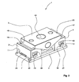
- the Fig. 2 shows the device in a perspective view in the mounted state.
- the wedge body 3,4 of the device 1 with its underside dovetail grooves 11,12 are guided on the spring 7 with the base plate teeth 24 of the base plate 2, while the support 5 with its two underside springs 19,20 in the top-side grooves 16,17 two wedge body 3,4 is slidably received.
- the locking lever 26,27 are in the representation of Fig. 2 in the "securing position" in which the plugs 39,40 are pressed or inserted into the recesses 35,36 and a horizontal displacement the wedge body 3,4 is excluded. Due to the slight interference fit between the plugs 39,40 and the recesses 35,36 these are even secured against falling out.
- the plugs 39,40 can continue to be connected captive, not shown, for example, with the base plate 2 or the wedge bodies 3,4.
- the support 5 at least one preferably centrally arranged central mounting hole 44 is introduced, which serves to connect the module, not shown, or functional modules to be fastened, for example in the form of a kitchen module or the like, the height adjustment is to be varied continuously by means of the device 1.
- the Fig. 3 shows a perspective (partial inside) view of the left-side wedge body 3 of the device in the assembled state, which corresponds to the internal structure of the wedge body 4 constructed for this gel-like image.
- the left wedge body 3 is horizontally slidably received in a known manner in the dovetail guide.
- the detent lever 26 is pressed down and held in this position ("securing position"), so that the base plate toothing 24 is brought into engagement with the detent lever toothing 30 and horizontal displacements of the wedge body 3 are excluded.
- This uncontrolled, automatic increase or decrease of the support 5 is impossible.
- a user removes the plugs 39, 40, lifts both latching levers 26, 27 without tools with their fingers until reaching the "adjustment position", guides the plugs 39, 40 under the latching levers 26, 27 into the recesses 35, 36, whereby they are held without further action in the raised position, and moves the wedge body 3,4 in opposite directions on the base plate 2 until the proper height adjustment of the device 1 is found.
- Both ends of the cylindrical spring 37 are in respective opposite holes 45,46 shallow depth, which are each introduced in a central region of a top 47 of the locking lever 26 and in the region of a ceiling surface 48 of the recess 35 in the wedge body 3, and thereby secured against lateral slipping ,
- the locking lever 26 is pivotably mounted by means of the bolt 33 within the first wedge body 3.
- Each upward movement of the detent lever 26 is in the in Fig. 3 illustrated "securing position" blocked by the inserted into the recess 35 plug 39.
- the positional fixing of the cylinder spring 38 in the locking lever 27 and the recess 36 (and its storage in the right wedge body 4, not shown in the Fig. 3 ) take place in an analogous manner (cf. Fig. 1 ).
- the inventive device 1 it is no longer necessary for the height adjustment process, the (screw) connection between the support 5 and a mounted thereon, not shown assembly, such as a kitchen module, during the adjustment procedure to solve and then tighten again.
- a mounted thereon, not shown assembly such as a kitchen module
Landscapes
- Engineering & Computer Science (AREA)
- General Engineering & Computer Science (AREA)
- Mechanical Engineering (AREA)
- Aviation & Aerospace Engineering (AREA)
- Connection Of Plates (AREA)
- Mutual Connection Of Rods And Tubes (AREA)
- Clamps And Clips (AREA)
- Pivots And Pivotal Connections (AREA)
- Spinning Or Twisting Of Yarns (AREA)
- Measuring Pulse, Heart Rate, Blood Pressure Or Blood Flow (AREA)
- Vehicle Body Suspensions (AREA)
Applications Claiming Priority (3)
| Application Number | Priority Date | Filing Date | Title |
|---|---|---|---|
| US482707P | 2007-11-30 | 2007-11-30 | |
| DE102007057617A DE102007057617B4 (de) | 2007-11-30 | 2007-11-30 | Vorrichtung zur werkzeuglosen Höhenverstellung einer Baugruppe |
| PCT/EP2008/061070 WO2009068331A1 (de) | 2007-11-30 | 2008-08-25 | Vorrichtung zur werkzeuglosen höhenverstellung einer baugruppe |
Publications (2)
| Publication Number | Publication Date |
|---|---|
| EP2227414A1 EP2227414A1 (de) | 2010-09-15 |
| EP2227414B1 true EP2227414B1 (de) | 2011-06-29 |
Family
ID=40620977
Family Applications (1)
| Application Number | Title | Priority Date | Filing Date |
|---|---|---|---|
| EP08803188A Not-in-force EP2227414B1 (de) | 2007-11-30 | 2008-08-25 | Vorrichtung zur werkzeuglosen höhenverstellung einer baugruppe |
Country Status (10)
| Country | Link |
|---|---|
| US (1) | US8646738B2 (https=) |
| EP (1) | EP2227414B1 (https=) |
| JP (1) | JP2011504845A (https=) |
| CN (1) | CN101888949B (https=) |
| AT (1) | ATE514626T1 (https=) |
| BR (1) | BRPI0821072A2 (https=) |
| CA (1) | CA2705189A1 (https=) |
| DE (1) | DE102007057617B4 (https=) |
| RU (1) | RU2470836C2 (https=) |
| WO (1) | WO2009068331A1 (https=) |
Families Citing this family (22)
| Publication number | Priority date | Publication date | Assignee | Title |
|---|---|---|---|---|
| DE102008062466A1 (de) * | 2008-12-17 | 2010-08-26 | Airbus Deutschland Gmbh | Vorrichtung zum Befestigen eines Objekts an einer Schiene |
| CN102620120A (zh) * | 2012-04-20 | 2012-08-01 | 大连华根机械有限公司 | 可调式垫铁装置 |
| NL2009393C2 (en) * | 2012-08-30 | 2014-03-03 | Driessen Aerospace Group Nv | Locking assembly for locking an aircraft interior structure to an internal mounting frame in an aircraft cabin. |
| US10808741B2 (en) * | 2013-03-15 | 2020-10-20 | Redshift Sports, LLC | Quick-release clamp with secondary retention mechanism |
| US9744634B2 (en) * | 2013-07-01 | 2017-08-29 | Dick PLANK | Support for workpieces |
| CN103586826B (zh) * | 2013-11-12 | 2015-05-20 | 苏州博众精工科技有限公司 | 一种支撑机构 |
| US10173301B2 (en) * | 2015-04-01 | 2019-01-08 | Robert Bilanzich | One-handed, quick action, locking vise |
| PL417068A1 (pl) * | 2016-05-02 | 2017-11-06 | Włodzimierz Grobelny | Przyrząd do montażu okien |
| CN105290438B (zh) * | 2015-11-20 | 2017-05-24 | 沈阳黎明航空发动机(集团)有限责任公司 | 一种提高零件加工刚性的自锁联动胀块装置 |
| NO20160849A1 (en) * | 2016-05-20 | 2017-09-11 | Autostore Tech As | Leveling Foot |
| US9895792B2 (en) * | 2016-06-21 | 2018-02-20 | Ju-Tan Chen | Workpiece clamp device capable for changing clamp angle |
| US9844855B1 (en) * | 2016-06-21 | 2017-12-19 | Po-Shen Chen | Workpiece clamp device with single side |
| CN106185198B (zh) * | 2016-08-11 | 2017-06-16 | 北京领邦智能装备股份公司 | 稳定的高度微调机构 |
| CN106772889B (zh) * | 2017-01-03 | 2018-11-20 | 中国科学院上海光学精密机械研究所 | 六维调整架 |
| CN106764315B (zh) * | 2017-03-14 | 2019-03-08 | 青岛鑫益广丰农业科技有限公司 | 一种可调式电力设备安装架 |
| TWM560964U (zh) * | 2017-11-17 | 2018-06-01 | Zhang Jun Wei | 工件定位之夾塊組合結構 |
| USD896053S1 (en) * | 2018-05-30 | 2020-09-15 | Uniclamp Sa (Pty) Ltd | Clamp |
| DE102018115725B4 (de) * | 2018-06-29 | 2022-07-14 | Airbus Operations Gmbh | Vorrichtung zum Ausgleichen von Maßtoleranzen eines Einbauelements in einer Kabine eines Fahrzeugs |
| US11680444B2 (en) * | 2020-01-24 | 2023-06-20 | Medic, Inc. | Leveler for window covering |
| CN111692620B (zh) * | 2020-07-07 | 2024-08-20 | 火星人厨具股份有限公司 | 一种集成灶中的吸油烟结构 |
| CN112656139A (zh) * | 2020-12-24 | 2021-04-16 | 重庆城市管理职业学院 | 麻醉精神病药管理的智能柜 |
| CN114183630B (zh) * | 2022-02-15 | 2022-04-22 | 氢山科技有限公司 | 一种氢能内燃机叉车用动力系统 |
Family Cites Families (18)
| Publication number | Priority date | Publication date | Assignee | Title |
|---|---|---|---|---|
| US194582A (en) * | 1877-08-28 | Improvement in apparatus for stretching felt jackets for rollers in paper-machines | ||
| US1557740A (en) * | 1925-06-03 | 1925-10-20 | Willard A Sullivan | Lock wedge device |
| US1794798A (en) * | 1927-05-02 | 1931-03-03 | Hiram C Weitzman | Jack |
| DE2039669C3 (de) * | 1970-08-10 | 1978-11-02 | Klaus 5500 Trier Goebel | Im Bereich einer Fugenkreuzung einer Plattenlage angeordnetes Lager zum Aufständern der Platten |
| DE2758340A1 (de) * | 1977-12-27 | 1979-07-05 | Pfister Waagen Gmbh | Hydrostatische stellvorrichtung |
| SU720246A1 (ru) * | 1978-04-10 | 1980-03-05 | Всесоюзный научно-исследовательский институт золота и редких металлов | Регулируема прокладка |
| US4269392A (en) * | 1979-09-17 | 1981-05-26 | Andersen Henry L | Jack mechanism |
| DE3122366A1 (de) * | 1981-06-05 | 1982-12-23 | Messerschmitt-Bölkow-Blohm GmbH, 8000 München | "verbindungseinrichtung zur befestigung von einbauelementen" |
| US4436268A (en) * | 1981-07-20 | 1984-03-13 | Schriever Frederick G | Self-aligning load leveling device |
| US5427349A (en) * | 1992-04-13 | 1995-06-27 | Reo Hydraulic Pierce & Form, Inc. | Adjustable base assembly |
| US5584464A (en) * | 1995-02-15 | 1996-12-17 | Unisorb Inc. | Quick adjustment heavy duty machinery mount |
| RU2156185C1 (ru) * | 1999-03-02 | 2000-09-20 | Ульяновский государственный технический университет | Устройство для микроподачи заготовок при шлифовании |
| CN1354824A (zh) * | 1999-03-17 | 2002-06-19 | 西门子Sgp交通技术有限公司 | 高度可调的垫板 |
| JP4338277B2 (ja) * | 2000-01-14 | 2009-10-07 | コンビ株式会社 | ブースタシート |
| NL1021107C2 (nl) * | 2002-07-18 | 2004-01-20 | Driessen Aircraft Holding B V | Modulaire kombuis voor in een vliegtuig of trein alsmede wand en module voor een dergelijke kombuis en daarmee uitgerust vliegtuig of trein. |
| US20050005544A1 (en) | 2003-07-10 | 2005-01-13 | Borowiecki Fabian A. | One piece decorative insulation and interior panel assembly |
| DE102004012262B4 (de) * | 2004-03-12 | 2010-01-07 | Airbus Deutschland Gmbh | Galley-Halterung |
| JP2006241930A (ja) * | 2005-03-07 | 2006-09-14 | Kanai:Kk | 高さ調整が可能な土台基礎用スペーサー |
-
2007
- 2007-11-30 DE DE102007057617A patent/DE102007057617B4/de not_active Expired - Fee Related
-
2008
- 2008-08-25 JP JP2010535308A patent/JP2011504845A/ja active Pending
- 2008-08-25 AT AT08803188T patent/ATE514626T1/de active
- 2008-08-25 WO PCT/EP2008/061070 patent/WO2009068331A1/de not_active Ceased
- 2008-08-25 CA CA2705189A patent/CA2705189A1/en not_active Abandoned
- 2008-08-25 RU RU2010120731/11A patent/RU2470836C2/ru not_active IP Right Cessation
- 2008-08-25 CN CN200880118621.2A patent/CN101888949B/zh not_active Expired - Fee Related
- 2008-08-25 EP EP08803188A patent/EP2227414B1/de not_active Not-in-force
- 2008-08-25 BR BRPI0821072-1A patent/BRPI0821072A2/pt not_active IP Right Cessation
-
2010
- 2010-05-12 US US12/778,687 patent/US8646738B2/en not_active Expired - Fee Related
Also Published As
| Publication number | Publication date |
|---|---|
| WO2009068331A1 (de) | 2009-06-04 |
| CA2705189A1 (en) | 2009-06-04 |
| BRPI0821072A2 (pt) | 2015-06-16 |
| DE102007057617B4 (de) | 2009-12-24 |
| US20100264269A1 (en) | 2010-10-21 |
| ATE514626T1 (de) | 2011-07-15 |
| CN101888949A (zh) | 2010-11-17 |
| RU2010120731A (ru) | 2012-01-10 |
| RU2470836C2 (ru) | 2012-12-27 |
| EP2227414A1 (de) | 2010-09-15 |
| CN101888949B (zh) | 2013-11-06 |
| DE102007057617A1 (de) | 2009-06-10 |
| US8646738B2 (en) | 2014-02-11 |
| JP2011504845A (ja) | 2011-02-17 |
Similar Documents
| Publication | Publication Date | Title |
|---|---|---|
| EP2227414B1 (de) | Vorrichtung zur werkzeuglosen höhenverstellung einer baugruppe | |
| EP2252508B1 (de) | Vorrichtung zur lösbaren bodenbefestigung von schränken oder dergleichen in bordküchen von flugzeugen | |
| EP3264943B1 (de) | Möbel und möbelbeschlag zur verbindung von möbelteilen | |
| AT507577B1 (de) | Möbelbeschlag zum lösbaren verbinden zweier möbelteile | |
| EP2186979A2 (de) | Türband für eine verdeckte Anordnung zwischen Türzarge und Türflügel | |
| EP1794052B1 (de) | Sitzbefestigungsvorrichtung | |
| DE29712180U1 (de) | Vorrichtung zur schnellösbaren, verschiebbaren und schnell arretierbaren Befestigung eines Fahrzeugausrüstungsteiles, wie z.B. eines Sitzes | |
| EP2142428A2 (de) | Vorrichtung zum festlegen von gegenständen | |
| EP2625062B1 (de) | Längsverstelleinrichtung für einen kraftfahrzeugsitz | |
| DE10229385A1 (de) | Einrichtung zur Verstellung und/oder Arretierung einer Baueinheit eines Verkehrs- oder Transportmittels | |
| EP2602190A2 (de) | Befestigungsvorrichtung | |
| DE69700556T2 (de) | Nach vorn bewegbarer Fahrzeugsitz, um zu einem hinteren Raum zu gelangen | |
| EP2668869A2 (de) | Lösbares Verriegelungselement | |
| EP3380360A1 (de) | Sitztiefenversteller | |
| WO2022083965A1 (de) | Baugruppe für einen verschiebbaren fahrzeugsitz | |
| DE102011085177B4 (de) | Antriebssystem für ein KFZ-Dachsystem | |
| EP1526981A1 (de) | Sicherheitseinrichtung für fahrzeugsitze | |
| EP4015749B1 (de) | Befestigungseinrichtung zur befestigung eines beschlagteils an einem eine nut aufweisenden rahmen einer gebäudeverschlusseinrichtung, gebäudeverschlusseinrichtung sowie verfahren zum befestigen eines beschlagteils an einem rahmen einer gebäudeverschlusseinrichtung | |
| DE102013209111B4 (de) | Einspannvorrichtung, insbesondere zur Aufnahme und zum Einspannen eines Bauteils, sowie Einspannsystem mit einer solchen Einspannvorrichtung | |
| DE19624979A1 (de) | Vorrichtung zur translatorischen Verstellung eines Sitzteils, insbesondere zur Sitzkissentiefenverstellung von Kraftfahrzeugsitzen | |
| EP2252510B1 (de) | Vorrichtung zum festlegen eines gegenstandes an einer schiene | |
| EP1607329A1 (de) | Schnellwechselbeschlag | |
| DE19926085A1 (de) | Mechanische Absorptionsvorrichtung | |
| EP1734330A1 (de) | Montagevorrichtung für ein Zielfernrohr | |
| EP3492677B1 (de) | Türöffner mit selbsthemmung des aufschraubstücks |
Legal Events
| Date | Code | Title | Description |
|---|---|---|---|
| PUAI | Public reference made under article 153(3) epc to a published international application that has entered the european phase |
Free format text: ORIGINAL CODE: 0009012 |
|
| 17P | Request for examination filed |
Effective date: 20100519 |
|
| AK | Designated contracting states |
Kind code of ref document: A1 Designated state(s): AT BE BG CH CY CZ DE DK EE ES FI FR GB GR HR HU IE IS IT LI LT LU LV MC MT NL NO PL PT RO SE SI SK TR |
|
| AX | Request for extension of the european patent |
Extension state: AL BA MK RS |
|
| RIN1 | Information on inventor provided before grant (corrected) |
Inventor name: BENSE, ROLF Inventor name: ISCHDONAT, NILS Inventor name: SCHMIDT-KORTENBUSCH, BENEDIKT Inventor name: STOOB, MELANIE |
|
| GRAP | Despatch of communication of intention to grant a patent |
Free format text: ORIGINAL CODE: EPIDOSNIGR1 |
|
| DAX | Request for extension of the european patent (deleted) | ||
| GRAS | Grant fee paid |
Free format text: ORIGINAL CODE: EPIDOSNIGR3 |
|
| GRAA | (expected) grant |
Free format text: ORIGINAL CODE: 0009210 |
|
| AK | Designated contracting states |
Kind code of ref document: B1 Designated state(s): AT BE BG CH CY CZ DE DK EE ES FI FR GB GR HR HU IE IS IT LI LT LU LV MC MT NL NO PL PT RO SE SI SK TR |
|
| REG | Reference to a national code |
Ref country code: GB Ref legal event code: FG4D Free format text: NOT ENGLISH |
|
| REG | Reference to a national code |
Ref country code: CH Ref legal event code: EP |
|
| REG | Reference to a national code |
Ref country code: IE Ref legal event code: FG4D Free format text: LANGUAGE OF EP DOCUMENT: GERMAN |
|
| REG | Reference to a national code |
Ref country code: DE Ref legal event code: R096 Ref document number: 502008004063 Country of ref document: DE Effective date: 20110818 |
|
| REG | Reference to a national code |
Ref country code: NL Ref legal event code: VDEP Effective date: 20110629 |
|
| PG25 | Lapsed in a contracting state [announced via postgrant information from national office to epo] |
Ref country code: SE Free format text: LAPSE BECAUSE OF FAILURE TO SUBMIT A TRANSLATION OF THE DESCRIPTION OR TO PAY THE FEE WITHIN THE PRESCRIBED TIME-LIMIT Effective date: 20110629 Ref country code: NO Free format text: LAPSE BECAUSE OF FAILURE TO SUBMIT A TRANSLATION OF THE DESCRIPTION OR TO PAY THE FEE WITHIN THE PRESCRIBED TIME-LIMIT Effective date: 20110929 Ref country code: HR Free format text: LAPSE BECAUSE OF FAILURE TO SUBMIT A TRANSLATION OF THE DESCRIPTION OR TO PAY THE FEE WITHIN THE PRESCRIBED TIME-LIMIT Effective date: 20110629 Ref country code: LT Free format text: LAPSE BECAUSE OF FAILURE TO SUBMIT A TRANSLATION OF THE DESCRIPTION OR TO PAY THE FEE WITHIN THE PRESCRIBED TIME-LIMIT Effective date: 20110629 |
|
| PG25 | Lapsed in a contracting state [announced via postgrant information from national office to epo] |
Ref country code: FI Free format text: LAPSE BECAUSE OF FAILURE TO SUBMIT A TRANSLATION OF THE DESCRIPTION OR TO PAY THE FEE WITHIN THE PRESCRIBED TIME-LIMIT Effective date: 20110629 Ref country code: LV Free format text: LAPSE BECAUSE OF FAILURE TO SUBMIT A TRANSLATION OF THE DESCRIPTION OR TO PAY THE FEE WITHIN THE PRESCRIBED TIME-LIMIT Effective date: 20110629 Ref country code: GR Free format text: LAPSE BECAUSE OF FAILURE TO SUBMIT A TRANSLATION OF THE DESCRIPTION OR TO PAY THE FEE WITHIN THE PRESCRIBED TIME-LIMIT Effective date: 20110930 Ref country code: SI Free format text: LAPSE BECAUSE OF FAILURE TO SUBMIT A TRANSLATION OF THE DESCRIPTION OR TO PAY THE FEE WITHIN THE PRESCRIBED TIME-LIMIT Effective date: 20110629 |
|
| PG25 | Lapsed in a contracting state [announced via postgrant information from national office to epo] |
Ref country code: MT Free format text: LAPSE BECAUSE OF FAILURE TO SUBMIT A TRANSLATION OF THE DESCRIPTION OR TO PAY THE FEE WITHIN THE PRESCRIBED TIME-LIMIT Effective date: 20110629 |
|
| REG | Reference to a national code |
Ref country code: IE Ref legal event code: FD4D |
|
| PG25 | Lapsed in a contracting state [announced via postgrant information from national office to epo] |
Ref country code: EE Free format text: LAPSE BECAUSE OF FAILURE TO SUBMIT A TRANSLATION OF THE DESCRIPTION OR TO PAY THE FEE WITHIN THE PRESCRIBED TIME-LIMIT Effective date: 20110629 Ref country code: PT Free format text: LAPSE BECAUSE OF FAILURE TO SUBMIT A TRANSLATION OF THE DESCRIPTION OR TO PAY THE FEE WITHIN THE PRESCRIBED TIME-LIMIT Effective date: 20111031 Ref country code: IS Free format text: LAPSE BECAUSE OF FAILURE TO SUBMIT A TRANSLATION OF THE DESCRIPTION OR TO PAY THE FEE WITHIN THE PRESCRIBED TIME-LIMIT Effective date: 20111029 Ref country code: IE Free format text: LAPSE BECAUSE OF FAILURE TO SUBMIT A TRANSLATION OF THE DESCRIPTION OR TO PAY THE FEE WITHIN THE PRESCRIBED TIME-LIMIT Effective date: 20110629 Ref country code: NL Free format text: LAPSE BECAUSE OF FAILURE TO SUBMIT A TRANSLATION OF THE DESCRIPTION OR TO PAY THE FEE WITHIN THE PRESCRIBED TIME-LIMIT Effective date: 20110629 Ref country code: CZ Free format text: LAPSE BECAUSE OF FAILURE TO SUBMIT A TRANSLATION OF THE DESCRIPTION OR TO PAY THE FEE WITHIN THE PRESCRIBED TIME-LIMIT Effective date: 20110629 |
|
| BERE | Be: lapsed |
Owner name: AIRBUS OPERATIONS G.M.B.H. Effective date: 20110831 |
|
| PG25 | Lapsed in a contracting state [announced via postgrant information from national office to epo] |
Ref country code: CY Free format text: LAPSE BECAUSE OF FAILURE TO SUBMIT A TRANSLATION OF THE DESCRIPTION OR TO PAY THE FEE WITHIN THE PRESCRIBED TIME-LIMIT Effective date: 20110629 Ref country code: RO Free format text: LAPSE BECAUSE OF FAILURE TO SUBMIT A TRANSLATION OF THE DESCRIPTION OR TO PAY THE FEE WITHIN THE PRESCRIBED TIME-LIMIT Effective date: 20110629 Ref country code: PL Free format text: LAPSE BECAUSE OF FAILURE TO SUBMIT A TRANSLATION OF THE DESCRIPTION OR TO PAY THE FEE WITHIN THE PRESCRIBED TIME-LIMIT Effective date: 20110629 Ref country code: SK Free format text: LAPSE BECAUSE OF FAILURE TO SUBMIT A TRANSLATION OF THE DESCRIPTION OR TO PAY THE FEE WITHIN THE PRESCRIBED TIME-LIMIT Effective date: 20110629 |
|
| PG25 | Lapsed in a contracting state [announced via postgrant information from national office to epo] |
Ref country code: MC Free format text: LAPSE BECAUSE OF NON-PAYMENT OF DUE FEES Effective date: 20110831 |
|
| PLBE | No opposition filed within time limit |
Free format text: ORIGINAL CODE: 0009261 |
|
| STAA | Information on the status of an ep patent application or granted ep patent |
Free format text: STATUS: NO OPPOSITION FILED WITHIN TIME LIMIT |
|
| PG25 | Lapsed in a contracting state [announced via postgrant information from national office to epo] |
Ref country code: BE Free format text: LAPSE BECAUSE OF NON-PAYMENT OF DUE FEES Effective date: 20110831 Ref country code: IT Free format text: LAPSE BECAUSE OF FAILURE TO SUBMIT A TRANSLATION OF THE DESCRIPTION OR TO PAY THE FEE WITHIN THE PRESCRIBED TIME-LIMIT Effective date: 20110629 |
|
| 26N | No opposition filed |
Effective date: 20120330 |
|
| PG25 | Lapsed in a contracting state [announced via postgrant information from national office to epo] |
Ref country code: DK Free format text: LAPSE BECAUSE OF FAILURE TO SUBMIT A TRANSLATION OF THE DESCRIPTION OR TO PAY THE FEE WITHIN THE PRESCRIBED TIME-LIMIT Effective date: 20110629 |
|
| REG | Reference to a national code |
Ref country code: DE Ref legal event code: R097 Ref document number: 502008004063 Country of ref document: DE Effective date: 20120330 |
|
| REG | Reference to a national code |
Ref country code: CH Ref legal event code: PL |
|
| PG25 | Lapsed in a contracting state [announced via postgrant information from national office to epo] |
Ref country code: CH Free format text: LAPSE BECAUSE OF NON-PAYMENT OF DUE FEES Effective date: 20120831 Ref country code: ES Free format text: LAPSE BECAUSE OF FAILURE TO SUBMIT A TRANSLATION OF THE DESCRIPTION OR TO PAY THE FEE WITHIN THE PRESCRIBED TIME-LIMIT Effective date: 20111010 Ref country code: LI Free format text: LAPSE BECAUSE OF NON-PAYMENT OF DUE FEES Effective date: 20120831 |
|
| PG25 | Lapsed in a contracting state [announced via postgrant information from national office to epo] |
Ref country code: LU Free format text: LAPSE BECAUSE OF NON-PAYMENT OF DUE FEES Effective date: 20110825 |
|
| PG25 | Lapsed in a contracting state [announced via postgrant information from national office to epo] |
Ref country code: BG Free format text: LAPSE BECAUSE OF FAILURE TO SUBMIT A TRANSLATION OF THE DESCRIPTION OR TO PAY THE FEE WITHIN THE PRESCRIBED TIME-LIMIT Effective date: 20110929 |
|
| PG25 | Lapsed in a contracting state [announced via postgrant information from national office to epo] |
Ref country code: TR Free format text: LAPSE BECAUSE OF FAILURE TO SUBMIT A TRANSLATION OF THE DESCRIPTION OR TO PAY THE FEE WITHIN THE PRESCRIBED TIME-LIMIT Effective date: 20110629 |
|
| PG25 | Lapsed in a contracting state [announced via postgrant information from national office to epo] |
Ref country code: HU Free format text: LAPSE BECAUSE OF FAILURE TO SUBMIT A TRANSLATION OF THE DESCRIPTION OR TO PAY THE FEE WITHIN THE PRESCRIBED TIME-LIMIT Effective date: 20110629 |
|
| REG | Reference to a national code |
Ref country code: AT Ref legal event code: MM01 Ref document number: 514626 Country of ref document: AT Kind code of ref document: T Effective date: 20130825 |
|
| PG25 | Lapsed in a contracting state [announced via postgrant information from national office to epo] |
Ref country code: AT Free format text: LAPSE BECAUSE OF NON-PAYMENT OF DUE FEES Effective date: 20130825 |
|
| REG | Reference to a national code |
Ref country code: FR Ref legal event code: PLFP Year of fee payment: 9 |
|
| PGFP | Annual fee paid to national office [announced via postgrant information from national office to epo] |
Ref country code: DE Payment date: 20160822 Year of fee payment: 9 Ref country code: GB Payment date: 20160819 Year of fee payment: 9 |
|
| PGFP | Annual fee paid to national office [announced via postgrant information from national office to epo] |
Ref country code: FR Payment date: 20160822 Year of fee payment: 9 |
|
| REG | Reference to a national code |
Ref country code: DE Ref legal event code: R119 Ref document number: 502008004063 Country of ref document: DE |
|
| GBPC | Gb: european patent ceased through non-payment of renewal fee |
Effective date: 20170825 |
|
| REG | Reference to a national code |
Ref country code: FR Ref legal event code: ST Effective date: 20180430 |
|
| PG25 | Lapsed in a contracting state [announced via postgrant information from national office to epo] |
Ref country code: DE Free format text: LAPSE BECAUSE OF NON-PAYMENT OF DUE FEES Effective date: 20180301 Ref country code: GB Free format text: LAPSE BECAUSE OF NON-PAYMENT OF DUE FEES Effective date: 20170825 |
|
| PG25 | Lapsed in a contracting state [announced via postgrant information from national office to epo] |
Ref country code: FR Free format text: LAPSE BECAUSE OF NON-PAYMENT OF DUE FEES Effective date: 20170831 |