EP2225976B1 - Vorrichtung zum Herstellen von Milchschaum - Google Patents
Vorrichtung zum Herstellen von Milchschaum Download PDFInfo
- Publication number
- EP2225976B1 EP2225976B1 EP09154238A EP09154238A EP2225976B1 EP 2225976 B1 EP2225976 B1 EP 2225976B1 EP 09154238 A EP09154238 A EP 09154238A EP 09154238 A EP09154238 A EP 09154238A EP 2225976 B1 EP2225976 B1 EP 2225976B1
- Authority
- EP
- European Patent Office
- Prior art keywords
- nozzle
- milk
- supply line
- air
- steam
- Prior art date
- Legal status (The legal status is an assumption and is not a legal conclusion. Google has not performed a legal analysis and makes no representation as to the accuracy of the status listed.)
- Active
Links
Images



Classifications
-
- A—HUMAN NECESSITIES
- A47—FURNITURE; DOMESTIC ARTICLES OR APPLIANCES; COFFEE MILLS; SPICE MILLS; SUCTION CLEANERS IN GENERAL
- A47J—KITCHEN EQUIPMENT; COFFEE MILLS; SPICE MILLS; APPARATUS FOR MAKING BEVERAGES
- A47J31/00—Apparatus for making beverages
- A47J31/44—Parts or details or accessories of beverage-making apparatus
-
- A—HUMAN NECESSITIES
- A47—FURNITURE; DOMESTIC ARTICLES OR APPLIANCES; COFFEE MILLS; SPICE MILLS; SUCTION CLEANERS IN GENERAL
- A47J—KITCHEN EQUIPMENT; COFFEE MILLS; SPICE MILLS; APPARATUS FOR MAKING BEVERAGES
- A47J31/00—Apparatus for making beverages
- A47J31/44—Parts or details or accessories of beverage-making apparatus
- A47J31/4485—Nozzles dispensing heated and foamed milk, i.e. milk is sucked from a milk container, heated and foamed inside the device, and subsequently dispensed from the nozzle
-
- A—HUMAN NECESSITIES
- A47—FURNITURE; DOMESTIC ARTICLES OR APPLIANCES; COFFEE MILLS; SPICE MILLS; SUCTION CLEANERS IN GENERAL
- A47J—KITCHEN EQUIPMENT; COFFEE MILLS; SPICE MILLS; APPARATUS FOR MAKING BEVERAGES
- A47J31/00—Apparatus for making beverages
- A47J31/44—Parts or details or accessories of beverage-making apparatus
- A47J31/46—Dispensing spouts, pumps, drain valves or like liquid transporting devices
- A47J31/469—Details of hydraulic circuits
Definitions
- the invention relates to a device for producing milk froth according to the preamble of claim 1.
- a device for producing milk foam for coffee drinks such as cappuccino or latte macchiato.
- the device may be part of an arrangement with a coffee machine. Of course, it is also conceivable to design the device as a single machine.
- a generic comparable device is from the WO 2005/102126 A2 known. It describes a coffee machine to which a mobile unit with a milk container and a Venturi-type nozzle for frothing milk can be docked.
- the nozzle has a nozzle inlet opening for the steam, an air inlet, a milk inlet and a nozzle outlet opening.
- To the nozzle outlet opening an angle pipe section is attached, which specifies the discharge opening.
- the air required for the generation of milk foam is present as ambient air and is sucked in by utilizing the suction effect in the nozzle.
- a disadvantage of this device for example, that the control or regulation of the air supply is relatively expensive.
- the milk foam and thus the quality of the coffee milk beverage often does not meet higher requirements.
- the milk froth produced with this device is relatively difficult to control with respect to temperature.
- the device is characterized by a relatively complicated structure. This applies in particular to the milk frother nozzle, which is designed in many parts. Thus, the nozzle would not be suitable as a disposable item.
- the DE 44 45 436 describes a frothing device for frothing milk for preparing cappuccino, with a supply line for steam, a supply line for air and a supply line for milk and with a mixing area in which the supply lines are merged, wherein the supply line for the air with a compressed air source for blowing the air is connected and wherein the injection of air is controllable.
- the EP 1 707 090 describes a device for producing milk foam and / or for heating milk, which is provided with a mixing element. This has at least one connectable to a steam supply line steam inlet channel, connectable to a milk supply line milk inlet channel, connectable to a discharge line discharge channel and an air inlet channel.
- the device should allow an advantageous control or regulation of the air supply.
- the device should continue to be characterized by a simple structure and improved hygiene.
- the device for producing milk froth and optionally for heating milk may have a steam supply line to which the nozzle provided with a nozzle inlet opening can connect in the flow direction.
- the nozzle may have a nozzle channel whose channel cross-section tapers from the nozzle inlet opening into a narrowed channel section. The channel cross-section can then expand in the direction of a nozzle outlet opening.
- the milk can be sucked from the milk container by utilizing the suction generated by the accelerated flow in the narrowed channel section into the nozzle.
- the air inlet is not located in the nozzle, but is located outside the nozzle, there are numerous advantages.
- the nozzle itself can be designed simply.
- the inventive arrangement can also have a favorable effect on hygiene, since only a few parts or sections of the device are acted upon with milk.
- the nozzle has a milk supply channel, which opens into the nozzle channel at approximately the narrowest point in the narrowed channel section.
- the device may comprise an air pump, which is for introducing air into the steam supply line via an air supply means with the air inlet opening connected or connectable.
- the air supply means may be an air supply line.
- Such a conduit may be configured as a hose.
- air supply means but also valves are conceivable, for example.
- the device can also be operated in such a way that milk (without the production of milk foam) can be heated.
- the air pump may be, for example, a diaphragm or compressor air pump.
- the device has control means via which the air pump for setting the mixing ratio of the steam-air mixture in the steam supply line can be controlled.
- the control means may include microprocessors.
- the air supply can be easily varied so that different milk or coffee milk drinks such as cappuccino, latte macchiato can be produced easily and with high quality.
- the air pump can also be controlled by means of the control means, however, that for the "hot milk" operation, the air pump is not activated or the air pump runs only in a partial load operation. With this arrangement, the temperature of the steam-air flow can be adjusted in a simple and advantageous manner. Further, the air supply by means of the described controlled Lucaspupe ensures that a sufficiently hot milk foam or hot milk can be produced.
- the device may comprise a water tank, a water pump connected thereto and an associated steam generator via which steam can be fed into the steam supply line. It may be particularly advantageous if the Device has control means for varying the pump power of the water pump.
- the nozzle is formed as a one-piece, preferably created in an injection molding, component which advantageously consists of plastic.
- a nozzle can be produced easily and inexpensively.
- the nozzle would be suitable as a disposable item.
- This one-piece component may have the nozzle inlet opening, the nozzle outlet opening and a milk supply line connection.
- the milk supply line connection can be designed as a milk intake for connecting the milk supply line, which surrounds a connected to the nozzle channel milk supply channel.
- the milk supply line can be releasably secured or attachable via a plug or snap connection to the milk intake.
- the nozzle exit opening of the nozzle may have an exposed discharge opening for dispensing the milk froth into a cup. Additional components for specifying a dispensing opening are therefore not necessary.
- the nozzle channel may have a deflection, so that the flow direction in the region of the nozzle inlet opening and the flow direction in the region of the nozzle outlet opening extend approximately at right angles to one another. It may then be advantageous if the milk supply channel in the region of the deflection approximately at right angles flows into the nozzle channel.
- each of the nozzle inlet opening and the nozzle outlet opening associated channel sections and the milk supply channel can be aligned at right angles.
- the nozzle channel can run straight, so that the main flow direction between the nozzle inlet opening and in the region of the nozzle outlet opening remains unchanged.
- Handling can be further simplified if the nozzle is connected or connectable to the steam supply line via a bayonet catch.
- the nozzle could also be connected in other ways releasably connected to the steam supply line.
- the nozzle may be pivotally attached to a lid portion of the milk container, preferably detachably fastened or fastened. In a starting position, the nozzle can be attached to save space on the milk container. The nozzle can be swung so far into a dispensing position that the milk foam can be dispensed directly into a cup.
- Another aspect of the invention relates to an arrangement with the device described above and a coffee machine for brewing coffee.
- Such coffee machines can be, for example, fully automatic coffee machines, in which coffee beans are first ground automatically and then brewed at the push of a button.
- the coffee machine can also be a machine that works with capsules, pouches or other portion packages.
- FIG. 1 shows an overall view of a designated 1 arrangement with a coffee machine 13 for brewing coffee K and a it docked device 24 for producing milk foam S.
- the coffee machine may be a conventional coffee machine with coffee beans or, for example, a so-called capsule machine.
- the basic structure of such coffee machines is known and familiar to the person skilled in the art, which is why a closer description of the coffee machine can be dispensed with.
- the coffee machine 13 is equipped with means, not shown here but described in detail below, for producing steam and for supplying air for emulsifying milk, steam and air for the production of milk foam.
- the device 13 consists of a milk container 5, in which a nozzle 2 is integrated.
- the milk container is closed by a lid part 24.
- the nozzle 2 is pivotally mounted.
- the nozzle is in FIG. 1 in a swung-out position (dispensing position) in which milk froth S can be dispensed into a cup (not shown).
- the nozzle is indicated in another output position.
- air L preferably supplied in the form of ambient air by means of an air pump 6 via an air supply line 30 under pressure of 10 to 100 kPa of the steam flow.
- the air inlet opening 18 is located in front of the nozzle with respect to the flow direction in front of the nozzle inlet opening 14.
- the line 27 can - for certain variants (see below Figure 3-7 ) - be understood as a dividing line, which divides the device 11 into two parts.
- the one part ie on the one hand, the components 7,8,9 for steam generation and on the other hand, the component 6 for the forced air supply, are associated with the coffee machine.
- the remaining part of the device can be disconnected from the coffee machine.
- the latter mobile part includes - like FIG. 2 Evidently, the nozzle 2 and the milk container 5.
- the nozzle 2 is formed by a one-piece component. Such a plastic component can be easily produced in an injection molding process.
- the nozzle 2 has, in addition to the nozzle inlet opening 14 and the nozzle outlet opening 17, a milk supply line connection in the form of a milk intake nozzle 20.
- Each of the nozzle inlet opening 14, the nozzle outlet opening 11 associated nozzle segments and the milk intake 20 are each aligned at right angles to each other.
- the indicated with dashed lines milk supply line 4 may be a flexible hose that can be plugged onto the milk intake 20.
- the nozzle 2 can be inserted into the milk container.
- latching means 31 are provided in the form of resilient latching arms on the cover part 24 of the milk container, with the aid of which the nozzle is latchingly receivable.
- the cover part 24 may consist of plastic and be a preferably one-piece injection-molded part.
- the milk container further contains a cup-shaped or trough-shaped main body 25, on which the lid part 24 (together with the nozzle 2) can be placed.
- Milk container and nozzle form a mobile unit that can be disconnected from the rest of the device and docked again.
- a milk container filled with fresh milk can be kept in a refrigerator.
- For the mobile milk container-nozzle unit essentially only four components (including milk supply line 4) are required, all made of plastic. The use of such less simple components has a favorable effect on handling and costs.
- FIG. 3 further shows that the air inlet is located outside the nozzle 2.
- the air inlet is defined by an air inlet port 28, via which the indicated with dashed lines air supply line 30 can be connected to the steam supply line 3.
- the air L is thus added to the vapor stream D via an air inlet opening.
- To the line 30 (not shown here) air pump is connected.
- the steam D is prepared as previously described with the aid of a (also not shown here) steam generator.
- a pipe section 23 which forms part of the steam supply line 3.
- the part 23 is designed as a T-piece of pipe and has the mentioned air inlet pipe 28 and a steam inlet port 29, via which in each case the lines indicated by dashed lines for the air L and the steam D can be connected.
- the air supply line 30 may be configured as a plastic tube.
- the hose designated 3 ' may be a temperature-resistant hose, for example, a silicone-reinforced hose or Teflon®.
- FIG. 3 shows - done by a bayonet lock.
- corresponding connecting means 21 are arranged on the nozzle input side.
- recess 22 is provided for the bayonet closure.
- other releasable fastening means are also conceivable.
- the milk container is designed approximately cuboid.
- Both cover part 24 and the main body 25 have a substantially approximately rectangular plan.
- On a side wall of the main body 25 is a recess 26 for receiving the nozzle 2 in an initial position.
- a recess 26 for receiving the nozzle 2 in an initial position.
- At the lid-side end of this side wall is an approximately U-shaped recess can be seen, in which the milk intake 20 is inserted.
- FIG. 4 the mobile unit with the milk container 5 and the nozzle is docked to the coffee machine. How out FIG. 4 As can be seen, the composite milk container 5 forms a compact unit with the base body 25 and the cover part 24.
- the nozzle can be pivoted between a starting position and a delivery position.
- the nozzle 2 is in a starting position in which the nozzle segment associated with the nozzle outlet opening 17 extends with the corresponding channel portion along the container wall of the main body 25 of the milk container.
- the nozzle 2 is swung out. In this position milk froth (or hot milk) can be dispensed directly into a cup (not shown).
- the user has the option of adjusting the swivel angle to the cup size. By pivoting but at the same time the previously described bayonet lock is brought into a closed position.
- the arrangement preferably has switching means (not shown) which are electrically or electronically connected to the control means for the water pump and the air pump.
- the switching means serve to check the presence and indicate whether the mobile unit is correctly coupled. Thereby, an unintentional escape of steam can be avoided, whereby a safe operation of the arrangement is ensured.
- the milk intake 20 surrounds a milk supply channel 19 which is connected to the nozzle channel 15 in the region about the narrowest point.
- the nozzle channel 15 initially has an outgoing from the nozzle inlet opening 14, approximately cylindrical portion, to which a tapered, approximately conical section connects. At the tapered portion of the designated 16 channel section adjoins, which dictates the narrowest point of the nozzle channel. At the narrowed nozzle channel then again an expanding, about conical channel section connects. In the area of the nozzle outlet opening 17, the nozzle channel finally has an approximately cylindrical channel section.
- FIGS. 8 and 9 show a comparison with the embodiment according to FIG. 3 modified air connection for the milk frother device.
- FIG. 8 shows a longitudinal section through a pipe section 23, which is part of the steam line 3.
- the air inlet is not aligned at right angles to the steam line, but the air is added via an oblique air inlet pipe 28 to the steam flow D.
- ⁇ is here for example about 45 °.
- other angles of inclination would also be conceivable (eg 30 ° ⁇ ⁇ 60 °).
- a diaphragm valve 35 can be seen, which is inserted into the air inlet pipe 28.
- FIG. 8 shows FIG. 8 in that the air inlet opening 18 predetermining air supply channel in the mouth region in the vapor stream in comparison to the vapor channel cross-section has a significantly smaller channel cross-section.
- the diameter of the air supply channel in the mouth region in the vapor stream can be between 0.2 and 2mm (eg, about 1mm), during which the diameter of the steam channel of the pipe section 23 is 4mm, for example.
- FIG. 10 is a respect to the embodiment according to FIG. 2 More detailed flow chart for a milk frother device 11 shown in a slightly modified form.
- the device 11 has a flow meter 36, which is in operative connection with the water pump 7 in terms of control and regulation.
- 33 denotes a check valve.
- the reference numeral 32 stands for a 3/2-way valve.
- a valve 34 is connected, via which in the case of an overpressure steam - instead of in the steam line 3 - can be drained. Excess residual water can be collected by a container 37.
- a diaphragm valve 35 is provided as a check valve.
Landscapes
- Engineering & Computer Science (AREA)
- Food Science & Technology (AREA)
- Apparatus For Making Beverages (AREA)
- Food-Manufacturing Devices (AREA)
Description
- Die Erfindung betrifft eine Vorrichtung zum Herstellen von Milchschaum gemäss dem Oberbegriff von Anspruch 1. Eine derartige Vorrichtung kann dazu verwendet werden, Milchschaum für Kaffeegetränke wie etwa Cappuccino oder Latte Macchiato herzustellen. Die Vorrichtung kann Teil einer Anordnung mit einer Kaffeemaschine sein. Selbstverständlich ist es aber auch denkbar, die Vorrichtung als Einzelmaschine auszugestalten.
- Systeme zum Herstellen von Milchschaum sind seit längerer Zeit gebräuchlich. Eine gattungsmässig vergleichbare Vorrichtung ist aus der
WO 2005/102126 A2 bekannt geworden. Darin ist eine Kaffeemaschine beschrieben, an die eine mobile Einheit mit einem Milchbehälter und einer Düse vom Venturi-Typ zum Aufschäumen von Milch andockbar ist. Die Düse weist eine Düseneintrittsöffnung für den Dampf, einen Lufteinlass, einen Milcheinlass sowie eine Düsenaustrittsöffnung auf. An die Düsenaustrittsöffnung ist ein Winkel-Rohrstück befestigt, das die Ausgabeöffnung vorgibt. Die für die Milchschaumerzeugung benötigte Luft liegt als Umgebungsluft vor und wird unter Ausnutzung des Saugeffekts in der Düse angesaugt. Nachteilig an dieser Vorrichtung ist beispielsweise, dass die Ansteuerung oder Regelung der Luftzufuhr relativ aufwendig ist. Dies hat zur Folge, dass der Milchschaum und damit die Qualität des Kaffee-Milchgetränks höheren Anforderungen oft nicht genügt. Beispielsweise hat sich in der Praxis gezeigt, dass der mit dieser Vorrichtung produzierte Milchschaum in Bezug auf die Temperatur relativ schwierig zu kontrollieren ist. Insgesamt zeichnet sich die Vorrichtung durch einen relativ komplizierten Aufbau aus. Dies betrifft insbesondere die Milchschäumer-Düse, die vielteilig ausgestaltet ist. Damit wäre die Düse nicht als Wegwerfartikel geeignet. - Die
DE 44 45 436 beschreibt eine Aufschäumvorrichtung zum Aufschäumen von Milch zur Zubereitung von Cappuccino, mit einer Zuleitung für Dampf, einer Zuleitung für Luft und einer Zuleitung für Milch und mit einem Mischbereich, in dem die Zuleitungen zusammengeführt werden, wobei die Zuleitung für die Luft mit einer Druckluftquelle zum Einblasen der Luft verbunden ist und wobei das Einblasen der Luft steuerbar ist. - Die
EP 1 707 090 beschreibt eine Vorrichtung zur Erzeugung von Milchschaum und/oder zum Erhitzen von Milch, die mit einem Mischelement versehen ist. Dieses weist zumindest einen mit einer Dampfzufuhrleitung verbindbaren Dampfeinlasskanal, einen mit einer Milchzufuhrleitung verbindbaren Milcheinlasskanal, einen mit einer Abgabeleitung verbindbaren Abgabekanal sowie einen Lufteinlasskanal auf. - Es ist daher eine Aufgabe der Erfindung, die Nachteile des Bekannten zu vermeiden und insbesondere eine Vorrichtung der eingangs genannten Art zu schaffen, mit der die Luftzufuhr für die Milchschaumerzeugung auf einfache Art und Weise variiert werden kann. Insbesondere soll die Vorrichtung eine vorteilhafte Ansteuerung oder Regelung der Luftzufuhr ermöglichen. Die Vorrichtung soll sich weiterhin durch einen einfachen Aufbau und verbesserte Hygiene auszeichnen.
- Diese Aufgaben werden erfindungsgemäss mit einer Vorrichtung erreicht, die die Merkmale in Anspruch 1 aufweist. Die Vorrichtung zum Herstellen von Milchschaum sowie gegebenenfalls zum Erhitzen von Milch kann eine Dampfzufuhrleitung aufweisen, an die in Strömungsrichtung die mit einer Düseneintrittsöffnung versehene Düse anschliessen kann. Die Düse kann einen Düsenkanal aufweisen, dessen Kanalquerschnitt sich ausgehend von der Düseneintrittsöffnung in einen verengten Kanalabschnitt verjüngt. Der Kanalquerschnitt kann sich anschliessend in Richtung einer Düsenaustrittsöffnung aufweiten. Die Milch kann aus dem Milchbehälter unter Ausnutzung der durch die beschleunigte Strömung im verengten Kanalabschnitt erzeugten Saugwirkung in die Düse eingesaugt werden. Dadurch, dass der Lufteinlass sich nicht in der Düse befindet, sondern ausserhalb der Düse angeordnet ist, ergeben sich zahlreiche Vorteile. So kann beispielsweise die Düse selbst einfach ausgestaltet sein. Die örtliche Verschiebung des Lufteinlasses hat aber auch steuerungs- oder reglungstechnische Vorteile. Weiterhin kann sich die erfindungsgemässe Anordnung auch günstig auf die Hygiene auswirken, da nur wenige Teile oder Abschnitte der Vorrichtung mit Milch beaufschlagt werden.
- Die Düse weist einen Milchzufuhrkanal auf, der etwa im Bereich der engsten Stelle im verengten Kanalabschnitt in den Düsenkanal mündet. Durch diese Anordnung lässt sich unter Ausnutzung des Saug-Effekts Milch besonders effizient in die Düse ansaugen.
- In einer ersten Ausführungsform kann die Vorrichtung eine Luftpumpe aufweisen, die zum Einbringen von Luft in die Dampfzufuhrleitung über ein Luftzuleitungsmittel mit der Lufteintrittsöffnung verbunden oder verbindbar ist. Das Luftzuleitungsmittel kann eine Luftzufuhrleitung sein. Eine solche Leitung kann als Schlauch ausgestaltet sein. Als Luftzuleitungsmittel sind aber zum Beispiel auch Ventile vorstellbar. Durch dieses Anschliessen einer Luftpumpe an die Dampfzufuhrleitung ist die Luftzufuhr besonders einfach einstellbar. Die Vorrichtung kann selbstverständlich auch derart betrieben werden, dass Milch (ohne Erzeugen von Milchschaum) erhitzbar ist.
- Bei der Luftpumpe kann es sich beispielsweise um eine Membran- oder Verdichterluftpumpe handeln.
- Besonders vorteilhaft kann es sein, wenn die Vorrichtung Steuermittel aufweist, über die die Luftpumpe zum Vorgeben des Mischungsverhältnisses des Dampf-Luft-Gemisches in der Dampfzufuhrleitung ansteuerbar ist. Die Steuermittel können Mikroprozessoren enthalten. Die Luftzufuhr kann so einfach variiert werden, wodurch unterschiedliche Milch- oder Kaffee-Milch-Getränke wie Cappuccino, Latte Macchiato einfach und mit hoher Qualität hergestellt werden können. Die Luftpumpe kann mittels der Steuermittel aber auch derart ansteuerbar sein, dass für den "heisse Milch"-Betrieb die Luftpumpe nicht aktiviert wird oder die Luftpumpe nur in einem Teillastbetrieb läuft. Mit dieser Anordnung kann die Temperatur des Dampf-Luft-Stroms auf einfache und vorteilhafte Art und Weise eingestellt werden. Weiter stellt die Luftzufuhr mittels der beschriebenen angesteuerten Luftpupe sicher, dass ein ausreichend heisser Milchschaum oder heisse Milch produziert werden kann.
- Weiter kann die Vorrichtung einen Wasserbehälter, eine daran angeschlossene Wasserpumpe und einen damit verbundenen Dampferzeuger aufweisen, über den Dampf in die Dampfzufuhrleitung einspeisbar ist. Besonders vorteilhaft kann es sein, wenn die Vorrichtung Steuermittel zum Variieren der Pumpleistung der Wasserpumpe aufweist.
- In einer weiteren Ausführungsform kann es vorteilhaft sein, wenn die Düse als einstückiges, vorzugsweise in einem Spritzgussverfahren geschaffenes, Bauteil ausgebildet ist, das vorteilhaft aus Kunststoff besteht. Eine solche Düse lässt sich einfach und kostengünstig herstellen. Damit wäre die Düse als Wegwerfartikel geeignet. Dieses einstückige Bauteil kann die Düseneintrittsöffnung, die Düsenaustrittsöffnung und einen Milchzufuhrleitungsanschluss aufweisen. Der Milchzufuhrleitungsanschluss kann dabei als Milchansaugstutzen zum Anschliessen der Milchzufuhrleitung ausgestaltet sein, welcher einen mit dem Düsenkanal verbundenen Milchzufuhrkanal umgibt. Die Milchzufuhrleitung kann über eine Steck- oder Schnappverbindung am Milchansaugstutzen lösbar befestigt oder befestigbar sein.
- Die Düsenaustrittsöffnung der Düse kann eine freiliegende Ausgabeöffnung zum Ausgeben des Milchschaums in eine Tasse. Zusätzliche Bauteile zum Vorgeben einer Ausgabeöffnung sind damit nicht nötig.
- Der Düsenkanal kann eine Umlenkung aufweisen, so dass die Strömungsrichtung im Bereich der Düseneintrittsöffnung und die Strömungsrichtung im Bereich der Düsenaustrittsöffnung etwa rechtwinklig zueinander verlaufen. Vorteilhaft kann es sodann sein, wenn der Milchzufuhrkanal im Bereich der Umlenkung etwa rechtwinklig in den Düsenkanal mündet. Somit können die jeweils der Düseneintrittsöffnung und der Düsenaustrittsöffnung zugeordneten Kanalabschnitte und der Milchzufuhrkanal je im rechten Winkel ausgerichtet sein. Selbstverständlich wäre es aber auch vorstellbar, dass der Düsenkanal gerade verlaufen kann, so dass die Hauptströmungsrichtung zwischen der Düseneintrittsöffnung und im Bereich der Düsenaustrittsöffnung unverändert bleibt.
- Die Handhabung lässt sich weiter vereinfachen, wenn die Düse über einen Bajonettverschluss an der Dampfzufuhrleitung angeschlossen oder anschliessbar ist. Selbstverständlich könnte die Düse aber auch auf andere Weise lösbar mit der Dampfzufuhrleitung verbunden werden.
- Die Düse kann schwenkbar an einem Deckelteil des Milchbehälters vorzugsweise lösbar befestigt oder befestigbar sein. In einer Ausgangsstellung kann die Düse platzsparend am Milchbehälter befestigt sein. Die Düse kann soweit in eine Ausgabestellung ausgeschwenkt werden, dass der Milchschaum direkt in eine Tasse ausgegeben werden kann.
- Ein weiterer Aspekt der Erfindung betrifft eine Anordnung mit der vorgängig beschriebenen Vorrichtung und einer Kaffeemaschine zum Brühen von Kaffee. Derartige Kaffeemaschinen können zum Beispiel Kaffee-Vollautomaten sein, bei denen Kaffeebohnen nach Knopfdruck zuerst automatisch gemahlen und dann gebrüht werden. Selbstverständlich kann die Kaffeemaschine auch eine Maschine sein, die mit Kapseln, Pouches oder andere Portionenverpackungen arbeitet.
- Weitere Einzelmerkmale und Vorteile der Erfindung ergeben sich aus der nachstehenden Beschreibung eines Ausführungsbeispiels und aus den Zeichnungen. Es zeigen:
- Figur 1
- eine Anordnung mit einer Kaffeemaschine und einer Vorrichtung zum Herstellen von Milchschaum,
- Figur 2
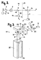
- eine stark vereinfachte schematische Darstellung ei- ner erfindungsgemässen Vorrichtung zum Herstellen von Milchschaum,
- Figur 3
- eine perspektivische Explosionsdarstellung der Vor- richtung zum Herstellen von Milchschaum für die An- ordnung gemäss
Figur 1 , - Figur 4
- eine Seitenansicht der Vorrichtung gemäss
Figur 3 , - Figur 5
- eine weitere Seitenansicht mit einem Teilschnitt der Vorrichtung mit einer Düse in einer Ausgangsstellung,
- Figur 6
- die Vorrichtung mit einer ausgeschwenkten Düse,
- Figur 7
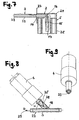
- eine Schnittdarstellung der Vorrichtung entlang der Schnittlinie A-A gemäss
Figur 5 , - Figur 8
- einen Längsschnitt durch ein Rohrstück der Dampfzu- fuhrleitung und eine daran angeschlossene Luftpumpe,
- Figur 9
- eine perspektivische Vorderansicht des Rohrstücks mit der Luftpumpe gemäss
Figur 8 , und - Figur 10
- eine schematische Darstellung einer weiteren Vorrich- tung zum Herstellen von Milchschaum.
-
Figur 1 zeigt eine Gesamtansicht einer mit 1 bezeichneten Anordnung mit einer Kaffeemaschine 13 zum Brühen von Kaffee K und einer daran angedockten Vorrichtung 24 zum Herstellen von Milchschaum S. Bei der Kaffeemaschine kann es sich um einen konventionellen Kaffeevollautomaten mit Kaffeebohnen oder beispielhaft auch um eine sogenannte Kapselmaschine handeln. Der Grundaufbau derartiger Kaffeemaschinen ist dem Fachmann bekannt und geläufig, weshalb auf einen näheren Beschrieb der Kaffeemaschine verzichtet werden kann. Die Kaffeemaschine 13 ist mit hier nicht gezeigten, jedoch nachfolgend im Detail beschriebenen Mitteln zum Erzeugen von Dampf und zum Zuführen von Luft zum Emulgieren von Milch, Dampf und Luft für die Milchschaumherstellung ausgestattet. - Wie
Figur 1 zeigt, besteht die Vorrichtung 13 aus einem Milchbehälter 5, in dem eine Düse 2 integriert ist. Der Milchbehälter ist mit einem Deckelteil 24 verschlossen. Innenseitig am Deckelteil 24 ist schwenkbar die Düse 2 befestigt. Die Düse befindet sich inFigur 1 in einer ausgeschwenkten Stellung (Ausgabestellung), in der Milchschaum S in eine (nicht dargestellte) Tasse abgegeben werden kann. Mit 2' ist die Düse in einer anderen Ausgabestellung angedeutet. - Aus der schematischen Darstellung gemäss
Figur 2 ist der prinzipielle Aufbau und die Funktionsweise der Milchschäumer-Vorrichtung 11 gezeigt. In der Vorrichtung 11 wird Dampf, Luft und Milch in einer Düse 2 miteinander vermischt und emulgiert (Strömungsrichtungen sind mit Pfeilen angedeutet). Der so erzeugte, mit S angedeutete Milchschaum gelangt schliesslich in eine (nicht dargestellte) Tasse oder einen anderen Aufnahmebehälter. Zum Herstellen von Dampf wird Wasser W einem Wasserbehälter 8 mit Hilfe einer Wasserpumpe 7 entnommen. Das Wasser wird anschliessend durch einen Dampferhitzer 9 geführt. Der Dampf wird dann über eine Dampfzufuhrleitung 3 zu einer Düse 2 geführt. Die Düse 2 weist einen Düsenkanal mit einem konvergentdivergenten Kanalquerschnitt auf. Die Düseneintrittsöffnung ist mit 14, die Düsenaustrittsöffnung mit 17 bezeichnet. Unter Ausnutzung der durch die beschleunigte Strömung in einem verengten Kanalabschnitt der Düse 2 erzeugten Saugwirkung wird Milch M über eine Milchzufuhrleitung 4 aus einem Milchbehälter 5 in die Düse 2 angesaugt. - Zur Schaumerzeugung muss dem Dampf Luft zugemischt werden. Dazu wird Luft L, vorzugsweise in Form von Umgebungsluft mit Hilfe einer Luftpumpe 6 über eine Luftzufuhrleitung 30 unter Druck von 10 bis 100 kPa der Dampfströmung zugeführt. Die Lufteintrittsöffnung 18 befindet sich in Bezug auf die Strömungsrichtung vor der Düseneintrittsöffnung 14 vor der Düse. Mit einer gestrichelten Linie 27 ist eine Gehäusewand einer Kaffeemaschine angedeutet. Die Linie 27 kann - für bestimmte Ausführungsvarianten (siehe nachfolgende
Figur 3-7 ) - als Trennlinie aufgefasst werden, die die Vorrichtung 11 in zwei Teile aufteilt. Der eine Teil, d.h. einerseits die Komponenten 7,8,9 für die Dampferzeugung und andererseits die Komponente 6 für die erzwungene Luftzuführung, sind der Kaffeemaschine zugeordnet. Der restliche Teil der Vorrichtung kann von der Kaffeemaschine abgekoppelt werden. Zum letztgenannten mobilen Teil gehören - wieFigur 2 zeigt - ersichtlicherweise die Düse 2 sowie der Milchbehälter 5. - In Abhängigkeit vom gewünschten Getränk (z.B. für Cappuccino oder Latte Macchiato) können unterschiedliche Luftvolumenströme in die Dampfleitung eingespeist werden. Die Steuerung des Luftvolumenstroms erfolgt mit Hilfe eines Steuermittels 12, mit dem die Pumpleistung verändert werden kann. Selbstverständlich kann die Vorrichtung 11 aber auch so betrieben werden, dass keine Luft eingespeist wird. Die Vorrichtung kann also auch zur Herstellung von heisser Milch verwendet werden. In der Luftzufuhrleitung 30 kann ein Regulierventil (nicht dargestellt) angeordnet sein. Anstatt eines Regulierventils wären alternativ auch Rückschlagventile oder betätigte Sperrventile denkbar. Die Dampfzufuhr wird vorzugsweise mit Hilfe eines Steuermittels 10 gesteuert, mit dem die Pumpleistung der Wasserpumpe 7 variiert werden kann. Die beiden Steuermittel 10 und 11 können selbstverständlich Bestandteil einer gemeinsamen EDV-Einrichtung sein.
- Konstruktive Details einer möglichen Ausgestaltung der Vorrichtung 11 sind aus
Figur 3 entnehmbar. Die Düse 2 wird durch ein einstückiges Bauteil gebildet. Ein derartiges Bauteil aus Kunststoff lässt sich einfach in einem Spritzgussverfahren herstellen. Die Düse 2 weist neben der Düseneintrittsöffnung 14 und der Düsenaustrittsöffnung 17 einen Milchzufuhrleitungsanschluss in Form eines Milchansaugstutzens 20 auf. Die jeweils der Düseneintrittsöffnung 14, der Düsenaustrittsöffnung 11 zugeordneten Düsensegmente und der Milchansaugstutzen 20 sind je im rechten Winkel zueinander ausgerichtet. Die mit gestrichelten Linien angedeutete Milchzufuhrleitung 4 kann ein flexibler Schlauch sein, der auf den Milchansaugstutzen 20 aufgesteckt werden kann. - Die Düse 2 kann in den Milchbehälter eingesetzt werden. Hierzu sind am Deckelteil 24 des Milchbehälters Rastmittel 31 in Form federnder Rastarme vorgesehen, mit deren Hilfe die Düse rastend aufnehmbar ist. Der Deckelteil 24 kann aus Kunststoff bestehen und ein vorzugsweise einstückiges Spritzgussteil sein. Der Milchbehälter enthält weiterhin einen becher- oder wannenförmigen Grundkörper 25, auf den der Deckelteil 24 (zusammen mit der Düse 2) aufgesetzt werden kann. Milchbehälter und Düse bilden eine mobile Einheit, die von der restlichen Vorrichtung abgekoppelt und wieder angedockt werden kann. Ein mit Frischmilch befüllter Milchbehälter kann in einem Kühlschrank aufbewahrt werden. Für die mobile Milchbehälter-Düse-Einheit sind im Wesentlichen nur vier Bauteile (inklusive Milchzufuhrleitung 4) erforderlich, die alle aus Kunststoff bestehen können. Die Verwendung derart weniger einfacher Bauteile wirkt sich günstig auf Handhabung und Kosten aus.
-
Figur 3 zeigt weiterhin, dass der Lufteinlass sich ausserhalb der Düse 2 befindet. Der Lufteinlass ist durch einen Lufteinlassstutzen 28 vorgegeben, über den die mit gestrichelten Linien angedeutete Luftzufuhrleitung 30 an die Dampfzufuhrleitung 3 anschliessbar ist. Die Luft L wird somit über eine Lufteintrittsöffnung dem Dampfstrom D zugegeben. An die Leitung 30 ist die (hier nicht dargestellte) Luftpumpe angeschlossen. Der Dampf D wird wie vorgängig beschrieben mit Hilfe eines (hier ebenfalls nicht dargestellten) Dampferzeugers hergestellt. Im Bereich der maschinenseitigen Schnittstelle befindet sich innerhalb des Gehäuses 27 ein Rohrstück 23, das einen Teil der Dampfzufuhrleitung 3 bildet. Das Teil 23 ist als T-Rohrstück ausgestaltet und weist den erwähnten Lufteinlassstutzen 28 und einen Dampfeinlassstutzen 29 auf, über die jeweils die mit gestrichelten Linien angedeuteten Leitungen für die Luft L und den Dampf D anschliessbar sind. Die Luftzufuhrleitung 30 kann als Kunststoffschlauch ausgestaltet sein. Der mit 3' bezeichnete Schlauch kann ein temperaturbeständiger Schlauch beispielsweise ein Silikon armierter Schlauch oder auch aus Teflon® sein. - Zum Andocken der mobilen Einheit enthaltend Milchbehälter und Düse 2 muss die Düse 2 mit dem Ausgang der Dampfzufuhrleitung 3 verbunden werden. Die lösbare Verbindung kann - wie beispielhaft
Figur 3 zeigt - durch einen Bajonettverschluss erfolgen. Hierzu sind düseneingangsseitig entsprechende Verbindungsmittel 21 angeordnet. An der Gehäusewand 27 ist eine zum Verbindungsmittel 21 komplementäre Aussparung 22 für den Bajonettverschluss vorgesehen. Denkbar sind aber auch andere lösbare Befestigungsmittel. - Wie
Figur 3 sodann zeigt, ist der Milchbehälter etwa quaderförmig ausgestaltet. Sowohl Deckelteil 24 als auch der Grundkörper 25 verfügen über einen im Wesentlichen etwa rechtwinkligen Grundriss. An einer Seitenwand des Grundkörpers 25 befindet sich eine Einbuchtung 26 zur Aufnahme der Düse 2 in einer Ausgangsstellung. Am deckelseitigen Ende dieser Seitenwand ist eine etwa U-förmige Aussparung erkennbar, in welche der Milchansaugstutzen 20 einführbar ist. - In
Figur 4 ist die mobile Einheit mit dem Milchbehälter 5 und der Düse an die Kaffeemaschine angedockt. Wie ausFigur 4 hervorgeht, bildet der zusammengesetzte Milchbehälter 5 mit dem Grundkörper 25 und dem Deckelteil 24 eine kompakte Einheit. - Wie aus den
Figuren 5 und 6 hervorgeht, kann die Düse zwischen einer Ausgangsstellung und einer Abgabestellung geschwenkt werden. InFigur 5 befindet sich die Düse 2 in einer Ausgangsstellung, in der sich das der Düsenaustrittsöffnung 17 zugeordnete Düsensegment mit dem entsprechenden Kanalabschnitt entlang der Behälterwand des Grundkörpers 25 des Milchbehälters erstreckt. InFigur 6 ist die Düse 2 ausgeschwenkt. In dieser Stellung kann Milchschaum (oder heisse Milch) direkt in eine (nicht dargestellte) Tasse abgegeben werden. Der Anwender hat die Möglichkeit, den Schwenkwinkel an die Tassengrösse anzupassen. Durch das Verschwenken wird aber auch gleichzeitig der vorgängig beschriebene Bajonettverschluss in eine Schliessstellung gebracht. Die Anordnung verfügt vorzugsweise über (nicht dargestellte) Schaltmittel, die mit den Steuermitteln für die Wasserpumpe und die Luftpumpe elektrisch oder elektronisch verbunden sind. Die Schaltmittel dienen zur Anwesenheitskontrolle und zeigen an, ob die mobile Einheit korrekt angekoppelt ist. Dadurch kann ein unbeabsichtigtes Entweichen von Dampf vermieden werden, wodurch ein sicherer Betrieb der Anordnung sichergestellt ist. - In
Figuren 5 und 6 ist weiterhin erkennbar, dass der Milchansaugstutzen 20 einen Milchzufuhrkanal 19 umgibt, der mit dem Düsenkanal 15 im Bereich etwa der engsten Stelle verbunden ist. - Aus der Schnittdarstellung gemäss
Figur 7 ist insbesondere die Ausgestaltung des Düsenkanals 15 erkennbar. Der Düsenkanal 15 weist zunächst einen von der Düseneintrittsöffnung 14 ausgehenden, etwa zylindrischen Abschnitt auf, an den ein sich verjüngender, etwa konischer Abschnitt anschliesst. An den sich verjüngenden Abschnitt schliesst der mit 16 bezeichnete Kanalabschnitt an, der die engste Stelle des Düsenkanals vorgibt. Am so verengten Düsenkanal schliesst dann wieder ein sich aufweitender, etwa konischer Kanalabschnitt an. Im Bereich der Düsenaustrittsöffnung 17 weist der Düsenkanal schliesslich einen etwa zylindrischen Kanalabschnitt auf. - Die
Figuren 8 und 9 zeigen einen gegenüber dem Ausführungsbeispiel gemässFigur 3 modifizierten Luftanschluss für die Milchschäumer-Vorrichtung.Figur 8 zeigt einen Längsschnitt durch ein Rohrstück 23, das Teil der Dampfleitung 3 ist. Im Gegensatz zum Ausführungsbeispiel gemässFigur 3 ist der Lufteinlassstutzen nicht rechtwinklig zur Dampfleitung ausgerichtet, sondern die Luft wird über einen schrägen Lufteinlassstutzen 28 dem Dampfstrom D zugegeben. InFigur 8 ist ein entsprechender Neigungswinkel mit α angedeutet, der hier beispielhaft etwa 45° beträgt. Selbstverständlich wären aber auch andere Neigungswinkel denkbar (z.B. 30° < α < 60°). Weiterhin ist ein Membranventil 35 erkennbar, das in den Lufteinlassstutzen 28 eingesteckt ist. An dieses Ventil 35 schliesst unmittelbar die Luftpumpe 6 an. Eine eigentliche Luftzufuhrleitung in Form eines separaten Schlauchstücks (vgl.Fig. 3 ) ist bei der Variante gemässFigur 8 nicht vorgesehen. Sodann zeigtFigur 8 , dass der die Lufteintrittsöffnung 18 vorgebende Luftzufuhrkanal im Mündungsbereich in den Dampfstrom im Vergleich zum Dampfkanalquerschnitt einen erheblich geringeren Kanalquerschnitt aufweist. Der Durchmesser des Luftzufuhrkanals im Mündungsbereich in den Dampfstrom kann zwischen 0.2 und 2mm (z.B. ca. 1mm) liegen, während der der Durchmesser des Dampfkanals des Rohrstücks 23 z.B. 4mm beträgt. - In
Figur 10 ist ein gegenüber dem Ausführungsbeispiel gemässFigur 2 detaillierteres Flussdiagramm für eine Milchschäumer-Vorrichtung 11 in einer leicht modifizierten Form dargestellt. AusFigur 10 ist etwa erkennbar, dass die Vorrichtung 11 einen Durchflussmesser 36 aufweist, der steuer- und regeltechnisch mit der Wasserpumpe 7 in Wirkverbindung steht. Mit 33 ist ein Rückschlagventil bezeichnet. Das Bezugszeichen 32 steht für ein 3/2-Wege-Ventil. An einem Ausgang des Ventils ist ein Ventil 34 angeschlossen, über das im Fall eines Überdrucks Dampf - anstatt in die Dampfleitung 3 - abgelassen werden kann. Überschüssiges Restwasser kann von einem Behälter 37 aufgefangen werden. Zum Schutz der Luftpumpe ist als Rückschlagventil ein Membranventil 35 vorgesehen.
Claims (16)
- Vorrichtung (11) zum Herstellen von Milchschaum mit einer Dampfzufuhrleitung (3), mit einer zur Erzielung einer Saugwirkung sich verengenden Düse (2), mit einer Milchzufuhrleitung (4), die derart mit der Düse verbunden ist, dass Milch aus einem Milchbehälter (5) unter Saugwirkung in die Düse (2) ansaugbar ist, und mit einem Lufteinlass zum Zumischen von Luft zum Erzeugen des Milchschaums, wobei der Lufteinlass eine Lufteintrittssöffnung (18) in der Dampfzufuhrleitung (3) ist, welche sich in Bezug auf die Strömungsrichtung vor einer Düseneintrittsöffnung (14) der Düse (2) befindet, dadurch gekennzeichnet, dass die Düse (2) einen Milchzufuhrkanal (19) aufweist, der etwa im Bereich der engsten Stelle im verengten Kanalabschnitt (16) in einen Düsenkanal (15) der Düse (2) mündet.
- Vorrichtung nach Anspruch 1, dadurch gekennzeichnet, dass sie eine Luftpumpe (6) aufweist, die zum Einbringen von Luft in die Dampfzufuhrleitung (3) über ein Luftzuleitungsmittel (4, 35) mit der Lufteintrittsöffnung (18) verbunden oder verbindbar ist.
- Vorrichtung nach Anspruch 2, dadurch gekennzeichnet, dass sie Steuermittel (10) aufweist, über die die Luftpumpe (6) zum Vorgeben des Mischungsverhältnisses des Dampf-LuftGemisches in der Dampfzufuhrleitung (3) ansteuerbar ist.
- Vorrichtung nach einem der Ansprüche 1 bis 3, dadurch gekennzeichnet, dass sie einen Wasserbehälter (8), eine daran angeschlossene Wasserpumpe (7) und einen damit verbundenen Dampferzeuger (9) aufweist, über den Dampf in die Dampfzufuhrleitung (3) einspeisbar ist.
- Vorrichtung nach Anspruch 4, dadurch gekennzeichnet, dass sie Steuermittel (12) zum Variieren der Pumpleistung der Wasserpumpe (7) aufweist.
- Vorrichtung nach einem der Ansprüche 1 bis 5, dadurch gekennzeichnet, dass die Düse (2) als einstückiges, vorzugsweise in einem Spritzgussverfahren geschaffenes Bauteil enthaltend- eine Düseneintrittsöffnung (14),- eine Düsenaustrittsöffnung (17), und- einen Milchzufuhrleitungsanschluss, insbesondere in Form eines einen Milchzufuhrkanal (19) umgebenden Milchansaugstutzens (20) zum Anschliessen der Milchzufuhrleitung (4),ausgebildet ist.
- Vorrichtung nach einem der Ansprüche 1 bis 6, dadurch gekennzeichnet, dass eine Düsenaustrittsöffnung (17) der Düse (2) eine Ausgabeöffnung zum Ausgeben des Milchschaums bildet, welche frei liegt.
- Vorrichtung nach einem der Ansprüche 1 bis 7, dadurch gekennzeichnet, dass der Düsenkanal (15) eine Umlenkung aufweist, so dass die Strömungsrichtung im Bereich der Düseneintrittsöffnung (14) und die Strömungsrichtung im Bereich der Düsenaustrittsöffnung (17) etwa rechtwinklig zueinander verlaufen.
- Vorrichtung nach Anspruch 8, dadurch gekennzeichnet, dass der Milchzufuhrkanal (19) im Bereich der Umlenkung etwa rechtwinklig in den Düsenkanal (15) einmündet.
- Vorrichtung nach einem der Ansprüche 1 bis 9, dadurch gekennzeichnet, dass die Düse (2) über einen Bajonettverschluss (21,22) an der Dampfzufuhrleitung (3) angeschlossen oder anschliessbar ist.
- Vorrichtung nach einem der Ansprüche 1 bis 9, dadurch gekennzeichnet, dass die Düse (2) schwenkbar an einem Deckelteil (24) eines Milchbehälters (5) vorzugsweise lösbar befestigt oder vorzugsweise lösbar befestigbar ist.
- Vorrichtung nach Anspruch 11, dadurch gekennzeichnet, dass der Milchbehälter (5) eine Einbuchtung (26) zur Aufnahme der Düse (2) in einer Ausgangsstellung aufweist.
- Vorrichtung nach einem der Ansprüche 1 bis 12 mit einem Milchbehälter (5), dadurch gekennzeichnet, dass der Milchbehälter (5) und die Düse (2) eine mobile Einheit bilden, die von der restlichen Vorrichtung abkoppelbar und wieder andockbar ist.
- Vorrichtung nach einem der Ansprüche 1 bis 13 mit einem Gehäuse (27) für die Komponenten (7, 8, 9) der Dampferzeugung und für eine Luftpumpe (6) für die erzwungene Luftzuführung in die Dampfzufuhrleitung (3) an der Lufteintrittsöffnung (18), dadurch gekennzeichnet, dass die Lufteintrittsöffnung (18) innerhalb des Gehäuses (27) angeordnet ist und dass die Düse (2) mit der Milchzuführleitung ausserhalb des Gehäuses und von diesem lösbar angeordnet ist.
- Vorrichtung nach einem der Ansprüche 1 bis 14, dadurch gekennzeichnet, dass der die Lufteintrittsöffnung (18) vorgeblende Luftzufuhrkanal im Mündungsbereich der Dampfzufuhrleitung (3) einen geringeren Querschnitt als die Dampfzufuhrleitung und vorzugsweise einen Durchmesser zwischen 0.2 mm und 2 mm aufweist.
- Anordnung (1) mit einer Vorrichtung (11) nach einem der Ansprüche 1 bis 12 und einer Kaffeemaschine (13) zum Brühen von Kaffee.
Priority Applications (14)
| Application Number | Priority Date | Filing Date | Title |
|---|---|---|---|
| ES09154238T ES2392011T3 (es) | 2009-03-03 | 2009-03-03 | Dispositivo para la preparación de espuma de leche |
| DK09154238.1T DK2225976T3 (da) | 2009-03-03 | 2009-03-03 | Indretning til fremstilling af mælkeskum |
| EP09154238A EP2225976B1 (de) | 2009-03-03 | 2009-03-03 | Vorrichtung zum Herstellen von Milchschaum |
| JP2011552425A JP2012519046A (ja) | 2009-03-03 | 2010-03-03 | ミルク泡を生成するための装置 |
| AU2010220366A AU2010220366A1 (en) | 2009-03-03 | 2010-03-03 | Device for producing milk froth |
| CA2754145A CA2754145A1 (en) | 2009-03-03 | 2010-03-03 | Device for producing milk froth |
| RU2011140018/12A RU2526011C2 (ru) | 2009-03-03 | 2010-03-03 | Устройство для получения молочной пены |
| ES10706241T ES2423026T3 (es) | 2009-03-03 | 2010-03-03 | Dispositivo para la elaboración de espuma de leche |
| DK10706241.6T DK2403387T3 (da) | 2009-03-03 | 2010-03-03 | Indretning til fremstilling af mælkeskum |
| PCT/EP2010/052649 WO2010100170A1 (de) | 2009-03-03 | 2010-03-03 | Vorrichtung zum herstellen von milchschaum |
| KR1020117022913A KR20110133578A (ko) | 2009-03-03 | 2010-03-03 | 우유 거품 제조 장치 |
| US13/254,130 US20110311694A1 (en) | 2009-03-03 | 2010-03-03 | Device for producing milk froth |
| EP10706241.6A EP2403387B1 (de) | 2009-03-03 | 2010-03-03 | Vorrichtung zum herstellen von milchschaum |
| IL214871A IL214871A (en) | 2009-03-03 | 2011-08-29 | A device for making milk foam |
Applications Claiming Priority (1)
| Application Number | Priority Date | Filing Date | Title |
|---|---|---|---|
| EP09154238A EP2225976B1 (de) | 2009-03-03 | 2009-03-03 | Vorrichtung zum Herstellen von Milchschaum |
Publications (2)
| Publication Number | Publication Date |
|---|---|
| EP2225976A1 EP2225976A1 (de) | 2010-09-08 |
| EP2225976B1 true EP2225976B1 (de) | 2012-09-26 |
Family
ID=40810773
Family Applications (2)
| Application Number | Title | Priority Date | Filing Date |
|---|---|---|---|
| EP09154238A Active EP2225976B1 (de) | 2009-03-03 | 2009-03-03 | Vorrichtung zum Herstellen von Milchschaum |
| EP10706241.6A Active EP2403387B1 (de) | 2009-03-03 | 2010-03-03 | Vorrichtung zum herstellen von milchschaum |
Family Applications After (1)
| Application Number | Title | Priority Date | Filing Date |
|---|---|---|---|
| EP10706241.6A Active EP2403387B1 (de) | 2009-03-03 | 2010-03-03 | Vorrichtung zum herstellen von milchschaum |
Country Status (11)
| Country | Link |
|---|---|
| US (1) | US20110311694A1 (de) |
| EP (2) | EP2225976B1 (de) |
| JP (1) | JP2012519046A (de) |
| KR (1) | KR20110133578A (de) |
| AU (1) | AU2010220366A1 (de) |
| CA (1) | CA2754145A1 (de) |
| DK (2) | DK2225976T3 (de) |
| ES (2) | ES2392011T3 (de) |
| IL (1) | IL214871A (de) |
| RU (1) | RU2526011C2 (de) |
| WO (1) | WO2010100170A1 (de) |
Families Citing this family (27)
| Publication number | Priority date | Publication date | Assignee | Title |
|---|---|---|---|---|
| EP2359725A1 (de) * | 2010-02-11 | 2011-08-24 | Koninklijke Philips Electronics N.V. | Vorrichtung zum Erwärmen und Aufschäumen einer Flüssigkeit |
| DE102011102734A1 (de) | 2011-05-20 | 2012-11-22 | WMF Württembergische Metallwarenfabrik Aktiengesellschaft | Vorrichtung zum Aufschäumen von Milch, Getränkebereiter mit dieser Vorrichtung und Verfahren zum Aufschäumen von Milch |
| DE102011077776B4 (de) * | 2011-06-17 | 2013-11-14 | Wmf Württembergische Metallwarenfabrik Ag | Vorrichtung zum Erhitzen und Aufschäumen eines Getränkeprodukts |
| DE202011110158U1 (de) * | 2011-07-29 | 2012-12-20 | Volker Barth | Vorrichtung zum Schäumen einer Flüssigkeit |
| DE102011084150A1 (de) * | 2011-10-07 | 2013-04-11 | Wmf Württembergische Metallwarenfabrik Ag | Luftpumpe zum Dosieren von Luft in Milchschäumsystemen |
| DE202011051719U1 (de) * | 2011-10-21 | 2012-01-24 | Schaerer Ag | Milchschäumvorrichtung sowie Kaffee- bzw. Espressomaschine mit einer solchen Milchschäumvorrichtung |
| ES2496450T3 (es) | 2012-03-06 | 2014-09-19 | Delica Ag | Dispositivo y procedimiento para producir espuma de leche y/o leche caliente |
| CN203693334U (zh) * | 2012-06-18 | 2014-07-09 | 广东新宝电器股份有限公司 | 牛奶发泡装置以及包括该装置的咖啡机 |
| EP2705783B1 (de) * | 2012-09-06 | 2014-07-30 | Miele & Cie. KG | Vorratsbehälter einer Entkalkungsvorrichtung, Getränkeautomat und Verfahren zur Entkalkung eines Getränkeautomaten |
| EP2994026B1 (de) | 2013-04-02 | 2019-06-12 | Koninklijke Philips N.V. | Kanne für getränke und getränkeherstellungsmaschine mit der besagten kanne |
| DE102013104339A1 (de) * | 2013-04-29 | 2014-10-30 | Melitta Professional Coffee Solutions GmbH & Co. KG | Verfahren und Vorrichtung zur Erzeugung von Milchprodukten, insbesondere Milchschaum |
| US10442610B2 (en) | 2014-03-11 | 2019-10-15 | Starbucks Corporation | Pod-based restrictors and methods |
| US20170127876A1 (en) * | 2014-06-27 | 2017-05-11 | Illycaffe' Spa | Machine for preparing beverages with frothed milk, in particular cappuccino or latte macchiato |
| EP3000363A1 (de) * | 2014-09-24 | 2016-03-30 | Qbo Coffee GmbH | Milchschäumergerät, Getränkezubereitungssystem und Getränkezubereitungsmaschine |
| ITUB20154020A1 (it) * | 2015-09-30 | 2017-03-30 | De Longhi Appliances Srl | Dispositivo per l?emulsione di una bevanda a base di latte per macchine da caffe |
| US11470998B2 (en) * | 2017-01-10 | 2022-10-18 | Nuwave, Llc | Automatic beverage maker reservoir heating system |
| IT201700037089A1 (it) * | 2017-04-04 | 2018-10-04 | Illycaffe Spa | Assieme di erogazione di una bevanda fredda |
| CH713954A1 (de) * | 2017-07-06 | 2019-01-15 | Steiner Ag Weggis | Milchmodul zur Erzeugung von Milchschaum oder Milchgetränken, vorzugsweise zum Einbau in eine Kaffeemaschine. |
| JP7393950B2 (ja) | 2017-07-06 | 2023-12-07 | シュタイナー・アーゲー・ウェギス | ミルクフォームまたはミルク飲料を生成するための、好ましくはコーヒーマシンに設置するためのミルクモジュール |
| JP2021509294A (ja) * | 2017-11-30 | 2021-03-25 | カログスト・アーゲーCarogusto Ag | 容器に配置された食品を処理する装置及び方法 |
| KR102068514B1 (ko) * | 2017-12-18 | 2020-02-11 | 정석원 | 유지방분 함유 원액에 미세 버블을 생성하는 장치 |
| CH716330A1 (de) * | 2019-06-17 | 2020-12-30 | Steiner Ag Weggis | Verfahren und Einrichtung für das Zubereiten eines Getränks, vorzugsweise von Milchschaum oder heisser Milch. |
| US11649153B2 (en) | 2020-06-25 | 2023-05-16 | TechFit Inc. | Beverage infusion apparatus and method for infusing gas into a beverage |
| US11649152B2 (en) | 2020-06-25 | 2023-05-16 | TechFit Inc. | Beverage infusion apparatus and method for infusing gas into a beverage |
| TW202226995A (zh) * | 2020-12-10 | 2022-07-16 | 義大利商銳玡自動販賣機工業股份有限公司 | 用於產生熱或冷、發泡或非發泡奶之奶模組之分配噴嘴 |
| CN113729486B (zh) * | 2021-09-30 | 2022-04-29 | 广东美的厨房电器制造有限公司 | 蒸汽烹饪设备 |
| DE102023125372B4 (de) * | 2023-09-19 | 2025-05-08 | Eugster/Frismag Ag | Milchmodul für Getränkezubereitungsvorrichtung mit eingangsseitigem Sensor |
Family Cites Families (13)
| Publication number | Priority date | Publication date | Assignee | Title |
|---|---|---|---|---|
| IT206829Z2 (it) * | 1986-04-18 | 1987-10-01 | Nuova Faema Spa | Simili, particolarmente per gruppo emulsionatore per macchine per il caffe' espresso da emulsionare aria, vapore e latte bar.per l'ottenimento di cappuccini e |
| US5330266A (en) * | 1993-10-18 | 1994-07-19 | Stubaus Leslie H | Cappuccino attachment for an espresso machine |
| DE4445436C2 (de) | 1994-12-20 | 1997-03-06 | Wmf Wuerttemberg Metallwaren | Aufschäumvorrichtung |
| DE29502594U1 (de) * | 1995-02-17 | 1995-04-06 | Arthur Eugster AG, Romanshorn | Mehrzweck-Aufschäumhilfe, insbesondere für Espressomaschinen |
| DE29605821U1 (de) * | 1996-03-28 | 1996-06-20 | Wu, Tsann-Kuen, Tainan Hsien | Aufgußeinrichtung für eine Venturi-artige Vorrichtung zur Blasenerzeugung |
| JP4097154B2 (ja) * | 2002-05-06 | 2008-06-11 | グルッポ・キムバリ・エス・ピー・エー | ミルクを加熱し泡立てるための装置 |
| JP4478467B2 (ja) * | 2003-08-07 | 2010-06-09 | フジコーン株式会社 | 飲料ディスペンサ用のミルクの供給方法並びにその装置 |
| ITMI20040777A1 (it) * | 2004-04-21 | 2004-07-21 | De Longhi Spa | Dispositivo e procedimento per la produzione di una bevanda a base di latte |
| EP1746920B1 (de) * | 2004-05-18 | 2010-04-14 | Nestec S.A. | Vorrichtung zum aufschäumen von milch mit externer milchansaugung |
| DE502006004096D1 (de) | 2005-03-29 | 2009-08-13 | Cafina Ag | Vorrichtung zur Erzeugung von Milchschaum und/oder zum Erhitzen von Milch |
| EP2025270B1 (de) * | 2007-08-16 | 2017-04-12 | Cafina AG | Vorrichtung zum Aufschäumen und Erhitzen von Milch |
| DE102009041809B4 (de) * | 2009-09-18 | 2013-05-16 | Franke Kaffeemaschinen Ag | Vorrichtung und Verfahren zum Aufschäumen eines flüssigen Lebensmittels, insbesondere von Milch |
| DE102011102734A1 (de) * | 2011-05-20 | 2012-11-22 | WMF Württembergische Metallwarenfabrik Aktiengesellschaft | Vorrichtung zum Aufschäumen von Milch, Getränkebereiter mit dieser Vorrichtung und Verfahren zum Aufschäumen von Milch |
-
2009
- 2009-03-03 ES ES09154238T patent/ES2392011T3/es active Active
- 2009-03-03 EP EP09154238A patent/EP2225976B1/de active Active
- 2009-03-03 DK DK09154238.1T patent/DK2225976T3/da active
-
2010
- 2010-03-03 ES ES10706241T patent/ES2423026T3/es active Active
- 2010-03-03 JP JP2011552425A patent/JP2012519046A/ja active Pending
- 2010-03-03 CA CA2754145A patent/CA2754145A1/en not_active Abandoned
- 2010-03-03 KR KR1020117022913A patent/KR20110133578A/ko not_active Withdrawn
- 2010-03-03 AU AU2010220366A patent/AU2010220366A1/en not_active Abandoned
- 2010-03-03 EP EP10706241.6A patent/EP2403387B1/de active Active
- 2010-03-03 RU RU2011140018/12A patent/RU2526011C2/ru not_active IP Right Cessation
- 2010-03-03 US US13/254,130 patent/US20110311694A1/en not_active Abandoned
- 2010-03-03 WO PCT/EP2010/052649 patent/WO2010100170A1/de not_active Ceased
- 2010-03-03 DK DK10706241.6T patent/DK2403387T3/da active
-
2011
- 2011-08-29 IL IL214871A patent/IL214871A/en not_active IP Right Cessation
Also Published As
| Publication number | Publication date |
|---|---|
| IL214871A0 (en) | 2011-11-30 |
| RU2011140018A (ru) | 2013-04-10 |
| EP2225976A1 (de) | 2010-09-08 |
| US20110311694A1 (en) | 2011-12-22 |
| ES2392011T3 (es) | 2012-12-03 |
| DK2225976T3 (da) | 2012-11-26 |
| EP2403387B1 (de) | 2013-05-01 |
| ES2423026T3 (es) | 2013-09-17 |
| CA2754145A1 (en) | 2010-09-10 |
| KR20110133578A (ko) | 2011-12-13 |
| WO2010100170A1 (de) | 2010-09-10 |
| DK2403387T3 (da) | 2013-07-22 |
| AU2010220366A1 (en) | 2011-09-22 |
| IL214871A (en) | 2014-09-30 |
| RU2526011C2 (ru) | 2014-08-20 |
| JP2012519046A (ja) | 2012-08-23 |
| EP2403387A1 (de) | 2012-01-11 |
Similar Documents
| Publication | Publication Date | Title |
|---|---|---|
| EP2225976A1 (de) | Vorrichtung zum Herstellen von Milchschaum | |
| DE102008058139B4 (de) | Aufschäumeinheit zum Aufschäumen von Milch und Anordnung enthaltend eine solche Aufschäumeinheit | |
| EP2636343B1 (de) | Vorrichtung und Verfahren zum Herstellen von Milchschaum und/oder erwärmter Milch | |
| EP2329749B1 (de) | Kaffeemaschine | |
| DE60215058T2 (de) | Vorrichtung zum erwärmen und aufschäumen von milch | |
| EP2534986B1 (de) | Vorrichtung zum Erhitzen und Aufschäumen eines Getränkeprodukts | |
| EP3079537B1 (de) | Milchschäumergerät | |
| EP2220973B1 (de) | Abgabevorrichtung für Milch und/oder Milchschaum und eine Kaffeemaschine mit einer derartigen Abgabevorrichtung | |
| EP3079536B1 (de) | Milchschäumergerät, getränkezubereitungssystem und getränkezubereitungsmaschine | |
| EP2589322B1 (de) | Kaffeemaschine, insbesondere Espressovollautomat | |
| EP3079538B1 (de) | Milchschäumergerät, getränkezubereitungssystem und getränkezubereitungsmaschine | |
| EP2768357B1 (de) | Milchschäumvorrichtung sowie kaffee- bzw. espressomaschine und getränkeverkaufsautomat mit einer solchen milchschäumvorrichtung | |
| EP2798989B1 (de) | Getränkezubereitungsvorrichtung mit Mitteln zur Milcherhitzung sowie Betriebsverfahren | |
| EP2897507B1 (de) | Vorrichtung zur herstellung von warmem oder kaltem milchschaum | |
| EP3079535B1 (de) | Milchschäumergerät | |
| EP0600826B1 (de) | Vorrichtung zur Erzeugung von Milchschaum für Cappuccino-Kaffee oder ähnlichen Getränken | |
| DE202009007945U1 (de) | Vorrichtung, die zur Verwendung zum Schaumigschlagen von Milch geeignet ist | |
| EP4670582A1 (de) | Milchaufschäumvorrichtung mit druckgasbeaufschlagung und verfahren zur herstellung von milchschaum | |
| DE202021105943U1 (de) | Milchaufschäumvorrichtung mit Druckgasbeaufschlagung |
Legal Events
| Date | Code | Title | Description |
|---|---|---|---|
| PUAI | Public reference made under article 153(3) epc to a published international application that has entered the european phase |
Free format text: ORIGINAL CODE: 0009012 |
|
| AK | Designated contracting states |
Kind code of ref document: A1 Designated state(s): AT BE BG CH CY CZ DE DK EE ES FI FR GB GR HR HU IE IS IT LI LT LU LV MC MK MT NL NO PL PT RO SE SI SK TR |
|
| AX | Request for extension of the european patent |
Extension state: AL BA RS |
|
| 17P | Request for examination filed |
Effective date: 20110207 |
|
| 17Q | First examination report despatched |
Effective date: 20110301 |
|
| AKX | Designation fees paid |
Designated state(s): AT BE BG CH CY CZ DE DK EE ES FI FR GB GR HR HU IE IS IT LI LT LU LV MC MK MT NL NO PL PT RO SE SI SK TR |
|
| GRAP | Despatch of communication of intention to grant a patent |
Free format text: ORIGINAL CODE: EPIDOSNIGR1 |
|
| GRAS | Grant fee paid |
Free format text: ORIGINAL CODE: EPIDOSNIGR3 |
|
| GRAA | (expected) grant |
Free format text: ORIGINAL CODE: 0009210 |
|
| AK | Designated contracting states |
Kind code of ref document: B1 Designated state(s): AT BE BG CH CY CZ DE DK EE ES FI FR GB GR HR HU IE IS IT LI LT LU LV MC MK MT NL NO PL PT RO SE SI SK TR |
|
| REG | Reference to a national code |
Ref country code: GB Ref legal event code: FG4D Free format text: NOT ENGLISH |
|
| REG | Reference to a national code |
Ref country code: CH Ref legal event code: EP |
|
| REG | Reference to a national code |
Ref country code: AT Ref legal event code: REF Ref document number: 576614 Country of ref document: AT Kind code of ref document: T Effective date: 20121015 Ref country code: CH Ref legal event code: NV Representative=s name: HEPP WENGER RYFFEL AG |
|
| REG | Reference to a national code |
Ref country code: IE Ref legal event code: FG4D Free format text: LANGUAGE OF EP DOCUMENT: GERMAN |
|
| REG | Reference to a national code |
Ref country code: DE Ref legal event code: R096 Ref document number: 502009004872 Country of ref document: DE Effective date: 20121122 |
|
| REG | Reference to a national code |
Ref country code: DK Ref legal event code: T3 |
|
| REG | Reference to a national code |
Ref country code: ES Ref legal event code: FG2A Ref document number: 2392011 Country of ref document: ES Kind code of ref document: T3 Effective date: 20121203 |
|
| REG | Reference to a national code |
Ref country code: NL Ref legal event code: T3 |
|
| PG25 | Lapsed in a contracting state [announced via postgrant information from national office to epo] |
Ref country code: LT Free format text: LAPSE BECAUSE OF FAILURE TO SUBMIT A TRANSLATION OF THE DESCRIPTION OR TO PAY THE FEE WITHIN THE PRESCRIBED TIME-LIMIT Effective date: 20120926 Ref country code: NO Free format text: LAPSE BECAUSE OF FAILURE TO SUBMIT A TRANSLATION OF THE DESCRIPTION OR TO PAY THE FEE WITHIN THE PRESCRIBED TIME-LIMIT Effective date: 20121226 Ref country code: FI Free format text: LAPSE BECAUSE OF FAILURE TO SUBMIT A TRANSLATION OF THE DESCRIPTION OR TO PAY THE FEE WITHIN THE PRESCRIBED TIME-LIMIT Effective date: 20120926 Ref country code: HR Free format text: LAPSE BECAUSE OF FAILURE TO SUBMIT A TRANSLATION OF THE DESCRIPTION OR TO PAY THE FEE WITHIN THE PRESCRIBED TIME-LIMIT Effective date: 20120926 |
|
| REG | Reference to a national code |
Ref country code: LT Ref legal event code: MG4D Effective date: 20120926 |
|
| PG25 | Lapsed in a contracting state [announced via postgrant information from national office to epo] |
Ref country code: SI Free format text: LAPSE BECAUSE OF FAILURE TO SUBMIT A TRANSLATION OF THE DESCRIPTION OR TO PAY THE FEE WITHIN THE PRESCRIBED TIME-LIMIT Effective date: 20120926 Ref country code: GR Free format text: LAPSE BECAUSE OF FAILURE TO SUBMIT A TRANSLATION OF THE DESCRIPTION OR TO PAY THE FEE WITHIN THE PRESCRIBED TIME-LIMIT Effective date: 20121227 Ref country code: SE Free format text: LAPSE BECAUSE OF FAILURE TO SUBMIT A TRANSLATION OF THE DESCRIPTION OR TO PAY THE FEE WITHIN THE PRESCRIBED TIME-LIMIT Effective date: 20120926 Ref country code: LV Free format text: LAPSE BECAUSE OF FAILURE TO SUBMIT A TRANSLATION OF THE DESCRIPTION OR TO PAY THE FEE WITHIN THE PRESCRIBED TIME-LIMIT Effective date: 20120926 |
|
| PG25 | Lapsed in a contracting state [announced via postgrant information from national office to epo] |
Ref country code: CZ Free format text: LAPSE BECAUSE OF FAILURE TO SUBMIT A TRANSLATION OF THE DESCRIPTION OR TO PAY THE FEE WITHIN THE PRESCRIBED TIME-LIMIT Effective date: 20120926 Ref country code: EE Free format text: LAPSE BECAUSE OF FAILURE TO SUBMIT A TRANSLATION OF THE DESCRIPTION OR TO PAY THE FEE WITHIN THE PRESCRIBED TIME-LIMIT Effective date: 20120926 Ref country code: IS Free format text: LAPSE BECAUSE OF FAILURE TO SUBMIT A TRANSLATION OF THE DESCRIPTION OR TO PAY THE FEE WITHIN THE PRESCRIBED TIME-LIMIT Effective date: 20130126 Ref country code: RO Free format text: LAPSE BECAUSE OF FAILURE TO SUBMIT A TRANSLATION OF THE DESCRIPTION OR TO PAY THE FEE WITHIN THE PRESCRIBED TIME-LIMIT Effective date: 20120926 |
|
| PG25 | Lapsed in a contracting state [announced via postgrant information from national office to epo] |
Ref country code: PT Free format text: LAPSE BECAUSE OF FAILURE TO SUBMIT A TRANSLATION OF THE DESCRIPTION OR TO PAY THE FEE WITHIN THE PRESCRIBED TIME-LIMIT Effective date: 20130128 Ref country code: PL Free format text: LAPSE BECAUSE OF FAILURE TO SUBMIT A TRANSLATION OF THE DESCRIPTION OR TO PAY THE FEE WITHIN THE PRESCRIBED TIME-LIMIT Effective date: 20120926 Ref country code: SK Free format text: LAPSE BECAUSE OF FAILURE TO SUBMIT A TRANSLATION OF THE DESCRIPTION OR TO PAY THE FEE WITHIN THE PRESCRIBED TIME-LIMIT Effective date: 20120926 |
|
| PG25 | Lapsed in a contracting state [announced via postgrant information from national office to epo] |
Ref country code: BG Free format text: LAPSE BECAUSE OF FAILURE TO SUBMIT A TRANSLATION OF THE DESCRIPTION OR TO PAY THE FEE WITHIN THE PRESCRIBED TIME-LIMIT Effective date: 20121226 |
|
| PLBE | No opposition filed within time limit |
Free format text: ORIGINAL CODE: 0009261 |
|
| STAA | Information on the status of an ep patent application or granted ep patent |
Free format text: STATUS: NO OPPOSITION FILED WITHIN TIME LIMIT |
|
| PG25 | Lapsed in a contracting state [announced via postgrant information from national office to epo] |
Ref country code: IT Free format text: LAPSE BECAUSE OF FAILURE TO SUBMIT A TRANSLATION OF THE DESCRIPTION OR TO PAY THE FEE WITHIN THE PRESCRIBED TIME-LIMIT Effective date: 20120926 |
|
| 26N | No opposition filed |
Effective date: 20130627 |
|
| REG | Reference to a national code |
Ref country code: DE Ref legal event code: R097 Ref document number: 502009004872 Country of ref document: DE Effective date: 20130627 |
|
| PG25 | Lapsed in a contracting state [announced via postgrant information from national office to epo] |
Ref country code: MC Free format text: LAPSE BECAUSE OF NON-PAYMENT OF DUE FEES Effective date: 20130331 |
|
| PG25 | Lapsed in a contracting state [announced via postgrant information from national office to epo] |
Ref country code: CY Free format text: LAPSE BECAUSE OF FAILURE TO SUBMIT A TRANSLATION OF THE DESCRIPTION OR TO PAY THE FEE WITHIN THE PRESCRIBED TIME-LIMIT Effective date: 20120926 |
|
| REG | Reference to a national code |
Ref country code: IE Ref legal event code: MM4A |
|
| PG25 | Lapsed in a contracting state [announced via postgrant information from national office to epo] |
Ref country code: IE Free format text: LAPSE BECAUSE OF NON-PAYMENT OF DUE FEES Effective date: 20130303 |
|
| PGFP | Annual fee paid to national office [announced via postgrant information from national office to epo] |
Ref country code: DK Payment date: 20140311 Year of fee payment: 6 Ref country code: NL Payment date: 20140308 Year of fee payment: 6 |
|
| PG25 | Lapsed in a contracting state [announced via postgrant information from national office to epo] |
Ref country code: MT Free format text: LAPSE BECAUSE OF FAILURE TO SUBMIT A TRANSLATION OF THE DESCRIPTION OR TO PAY THE FEE WITHIN THE PRESCRIBED TIME-LIMIT Effective date: 20120926 |
|
| PGFP | Annual fee paid to national office [announced via postgrant information from national office to epo] |
Ref country code: BE Payment date: 20140312 Year of fee payment: 6 |
|
| PGFP | Annual fee paid to national office [announced via postgrant information from national office to epo] |
Ref country code: ES Payment date: 20140227 Year of fee payment: 6 |
|
| PGFP | Annual fee paid to national office [announced via postgrant information from national office to epo] |
Ref country code: GB Payment date: 20150225 Year of fee payment: 7 |
|
| PG25 | Lapsed in a contracting state [announced via postgrant information from national office to epo] |
Ref country code: TR Free format text: LAPSE BECAUSE OF FAILURE TO SUBMIT A TRANSLATION OF THE DESCRIPTION OR TO PAY THE FEE WITHIN THE PRESCRIBED TIME-LIMIT Effective date: 20120926 |
|
| PG25 | Lapsed in a contracting state [announced via postgrant information from national office to epo] |
Ref country code: LU Free format text: LAPSE BECAUSE OF NON-PAYMENT OF DUE FEES Effective date: 20130303 Ref country code: HU Free format text: LAPSE BECAUSE OF FAILURE TO SUBMIT A TRANSLATION OF THE DESCRIPTION OR TO PAY THE FEE WITHIN THE PRESCRIBED TIME-LIMIT; INVALID AB INITIO Effective date: 20090303 Ref country code: MK Free format text: LAPSE BECAUSE OF FAILURE TO SUBMIT A TRANSLATION OF THE DESCRIPTION OR TO PAY THE FEE WITHIN THE PRESCRIBED TIME-LIMIT Effective date: 20120926 |
|
| REG | Reference to a national code |
Ref country code: DK Ref legal event code: EBP Effective date: 20150331 |
|
| REG | Reference to a national code |
Ref country code: NL Ref legal event code: MM Effective date: 20150401 |
|
| REG | Reference to a national code |
Ref country code: FR Ref legal event code: PLFP Year of fee payment: 8 |
|
| PG25 | Lapsed in a contracting state [announced via postgrant information from national office to epo] |
Ref country code: DK Free format text: LAPSE BECAUSE OF NON-PAYMENT OF DUE FEES Effective date: 20150331 |
|
| GBPC | Gb: european patent ceased through non-payment of renewal fee |
Effective date: 20160303 |
|
| PG25 | Lapsed in a contracting state [announced via postgrant information from national office to epo] |
Ref country code: GB Free format text: LAPSE BECAUSE OF NON-PAYMENT OF DUE FEES Effective date: 20160303 |
|
| REG | Reference to a national code |
Ref country code: FR Ref legal event code: PLFP Year of fee payment: 9 |
|
| PGFP | Annual fee paid to national office [announced via postgrant information from national office to epo] |
Ref country code: FR Payment date: 20170313 Year of fee payment: 9 |
|
| PG25 | Lapsed in a contracting state [announced via postgrant information from national office to epo] |
Ref country code: NL Free format text: LAPSE BECAUSE OF NON-PAYMENT OF DUE FEES Effective date: 20150401 Ref country code: ES Free format text: LAPSE BECAUSE OF NON-PAYMENT OF DUE FEES Effective date: 20150304 |
|
| PG25 | Lapsed in a contracting state [announced via postgrant information from national office to epo] |
Ref country code: BE Free format text: LAPSE BECAUSE OF NON-PAYMENT OF DUE FEES Effective date: 20150331 |
|
| REG | Reference to a national code |
Ref country code: ES Ref legal event code: FD2A Effective date: 20180627 |
|
| PG25 | Lapsed in a contracting state [announced via postgrant information from national office to epo] |
Ref country code: FR Free format text: LAPSE BECAUSE OF NON-PAYMENT OF DUE FEES Effective date: 20180331 |
|
| PGFP | Annual fee paid to national office [announced via postgrant information from national office to epo] |
Ref country code: CH Payment date: 20250401 Year of fee payment: 17 |
|
| REG | Reference to a national code |
Ref country code: CH Ref legal event code: U11 Free format text: ST27 STATUS EVENT CODE: U-0-0-U10-U11 (AS PROVIDED BY THE NATIONAL OFFICE) Effective date: 20260401 |
|
| PGFP | Annual fee paid to national office [announced via postgrant information from national office to epo] |
Ref country code: DE Payment date: 20260204 Year of fee payment: 18 |
|
| PGFP | Annual fee paid to national office [announced via postgrant information from national office to epo] |
Ref country code: AT Payment date: 20260225 Year of fee payment: 18 |