EP2224977B1 - Système de surveillance d'analyte et de distribution de fluide - Google Patents
Système de surveillance d'analyte et de distribution de fluide Download PDFInfo
- Publication number
- EP2224977B1 EP2224977B1 EP08851596.0A EP08851596A EP2224977B1 EP 2224977 B1 EP2224977 B1 EP 2224977B1 EP 08851596 A EP08851596 A EP 08851596A EP 2224977 B1 EP2224977 B1 EP 2224977B1
- Authority
- EP
- European Patent Office
- Prior art keywords
- tip
- unit
- patch unit
- monitoring
- patch
- Prior art date
- Legal status (The legal status is an assumption and is not a legal conclusion. Google has not performed a legal analysis and makes no representation as to the accuracy of the status listed.)
- Active
Links
- 238000012544 monitoring process Methods 0.000 title claims description 149
- 239000012530 fluid Substances 0.000 title claims description 63
- 239000012491 analyte Substances 0.000 title claims description 59
- NOESYZHRGYRDHS-UHFFFAOYSA-N insulin Chemical compound N1C(=O)C(NC(=O)C(CCC(N)=O)NC(=O)C(CCC(O)=O)NC(=O)C(C(C)C)NC(=O)C(NC(=O)CN)C(C)CC)CSSCC(C(NC(CO)C(=O)NC(CC(C)C)C(=O)NC(CC=2C=CC(O)=CC=2)C(=O)NC(CCC(N)=O)C(=O)NC(CC(C)C)C(=O)NC(CCC(O)=O)C(=O)NC(CC(N)=O)C(=O)NC(CC=2C=CC(O)=CC=2)C(=O)NC(CSSCC(NC(=O)C(C(C)C)NC(=O)C(CC(C)C)NC(=O)C(CC=2C=CC(O)=CC=2)NC(=O)C(CC(C)C)NC(=O)C(C)NC(=O)C(CCC(O)=O)NC(=O)C(C(C)C)NC(=O)C(CC(C)C)NC(=O)C(CC=2NC=NC=2)NC(=O)C(CO)NC(=O)CNC2=O)C(=O)NCC(=O)NC(CCC(O)=O)C(=O)NC(CCCNC(N)=N)C(=O)NCC(=O)NC(CC=3C=CC=CC=3)C(=O)NC(CC=3C=CC=CC=3)C(=O)NC(CC=3C=CC(O)=CC=3)C(=O)NC(C(C)O)C(=O)N3C(CCC3)C(=O)NC(CCCCN)C(=O)NC(C)C(O)=O)C(=O)NC(CC(N)=O)C(O)=O)=O)NC(=O)C(C(C)CC)NC(=O)C(CO)NC(=O)C(C(C)O)NC(=O)C1CSSCC2NC(=O)C(CC(C)C)NC(=O)C(NC(=O)C(CCC(N)=O)NC(=O)C(CC(N)=O)NC(=O)C(NC(=O)C(N)CC=1C=CC=CC=1)C(C)C)CC1=CN=CN1 NOESYZHRGYRDHS-UHFFFAOYSA-N 0.000 claims description 80
- 230000007246 mechanism Effects 0.000 claims description 66
- WQZGKKKJIJFFOK-GASJEMHNSA-N Glucose Natural products OC[C@H]1OC(O)[C@H](O)[C@@H](O)[C@@H]1O WQZGKKKJIJFFOK-GASJEMHNSA-N 0.000 claims description 53
- 239000008103 glucose Substances 0.000 claims description 53
- 102000004877 Insulin Human genes 0.000 claims description 40
- 108090001061 Insulin Proteins 0.000 claims description 40
- 229940125396 insulin Drugs 0.000 claims description 40
- 238000005086 pumping Methods 0.000 claims description 35
- 230000003287 optical effect Effects 0.000 claims description 31
- 239000000523 sample Substances 0.000 claims description 15
- 238000007920 subcutaneous administration Methods 0.000 claims description 15
- 230000001225 therapeutic effect Effects 0.000 claims description 10
- 238000012546 transfer Methods 0.000 claims description 10
- 238000004891 communication Methods 0.000 claims description 9
- 125000002791 glucosyl group Chemical group C1([C@H](O)[C@@H](O)[C@H](O)[C@H](O1)CO)* 0.000 claims description 4
- 238000012384 transportation and delivery Methods 0.000 description 39
- 238000003780 insertion Methods 0.000 description 22
- 230000037431 insertion Effects 0.000 description 22
- 238000000034 method Methods 0.000 description 15
- 210000003722 extracellular fluid Anatomy 0.000 description 13
- 206010033675 panniculitis Diseases 0.000 description 10
- 210000004304 subcutaneous tissue Anatomy 0.000 description 10
- 206010012601 diabetes mellitus Diseases 0.000 description 8
- 238000009792 diffusion process Methods 0.000 description 8
- 210000004379 membrane Anatomy 0.000 description 8
- 239000012528 membrane Substances 0.000 description 8
- 230000002572 peristaltic effect Effects 0.000 description 8
- 210000004369 blood Anatomy 0.000 description 7
- 239000008280 blood Substances 0.000 description 7
- 238000005259 measurement Methods 0.000 description 7
- 239000000243 solution Substances 0.000 description 7
- 238000001069 Raman spectroscopy Methods 0.000 description 6
- 238000001802 infusion Methods 0.000 description 6
- 238000001690 micro-dialysis Methods 0.000 description 6
- 239000000853 adhesive Substances 0.000 description 5
- 230000001070 adhesive effect Effects 0.000 description 5
- 238000002347 injection Methods 0.000 description 5
- 239000007924 injection Substances 0.000 description 5
- 230000000149 penetrating effect Effects 0.000 description 5
- 238000001228 spectrum Methods 0.000 description 5
- 210000001519 tissue Anatomy 0.000 description 5
- 235000012054 meals Nutrition 0.000 description 4
- 239000002609 medium Substances 0.000 description 4
- 239000013307 optical fiber Substances 0.000 description 4
- 108090000790 Enzymes Proteins 0.000 description 3
- 102000004190 Enzymes Human genes 0.000 description 3
- 108010015776 Glucose oxidase Proteins 0.000 description 3
- 239000004366 Glucose oxidase Substances 0.000 description 3
- 208000013016 Hypoglycemia Diseases 0.000 description 3
- 239000013078 crystal Substances 0.000 description 3
- 229940079593 drug Drugs 0.000 description 3
- 239000003814 drug Substances 0.000 description 3
- 230000000694 effects Effects 0.000 description 3
- 238000003487 electrochemical reaction Methods 0.000 description 3
- 238000005516 engineering process Methods 0.000 description 3
- 229940088598 enzyme Drugs 0.000 description 3
- 239000000835 fiber Substances 0.000 description 3
- 239000011521 glass Substances 0.000 description 3
- 229940116332 glucose oxidase Drugs 0.000 description 3
- 235000019420 glucose oxidase Nutrition 0.000 description 3
- 230000002218 hypoglycaemic effect Effects 0.000 description 3
- 239000010410 layer Substances 0.000 description 3
- 230000033001 locomotion Effects 0.000 description 3
- 239000000463 material Substances 0.000 description 3
- 210000000496 pancreas Anatomy 0.000 description 3
- 239000004033 plastic Substances 0.000 description 3
- 230000001902 propagating effect Effects 0.000 description 3
- 241000894007 species Species 0.000 description 3
- 239000000126 substance Substances 0.000 description 3
- 238000012360 testing method Methods 0.000 description 3
- 229920002307 Dextran Polymers 0.000 description 2
- 238000002835 absorbance Methods 0.000 description 2
- 238000004458 analytical method Methods 0.000 description 2
- 238000004873 anchoring Methods 0.000 description 2
- 238000000149 argon plasma sintering Methods 0.000 description 2
- 230000008859 change Effects 0.000 description 2
- 238000009429 electrical wiring Methods 0.000 description 2
- 230000031700 light absorption Effects 0.000 description 2
- 230000008569 process Effects 0.000 description 2
- 230000001012 protector Effects 0.000 description 2
- 238000011084 recovery Methods 0.000 description 2
- 230000002441 reversible effect Effects 0.000 description 2
- 238000010183 spectrum analysis Methods 0.000 description 2
- -1 without limitation Substances 0.000 description 2
- 108010062580 Concanavalin A Proteins 0.000 description 1
- 108090001090 Lectins Proteins 0.000 description 1
- 102000004856 Lectins Human genes 0.000 description 1
- 238000004497 NIR spectroscopy Methods 0.000 description 1
- 238000001237 Raman spectrum Methods 0.000 description 1
- FAPWRFPIFSIZLT-UHFFFAOYSA-M Sodium chloride Chemical compound [Na+].[Cl-] FAPWRFPIFSIZLT-UHFFFAOYSA-M 0.000 description 1
- 206010067584 Type 1 diabetes mellitus Diseases 0.000 description 1
- 206010057362 Underdose Diseases 0.000 description 1
- 239000012790 adhesive layer Substances 0.000 description 1
- 210000000577 adipose tissue Anatomy 0.000 description 1
- 108010004469 allophycocyanin Proteins 0.000 description 1
- 230000004075 alteration Effects 0.000 description 1
- 239000012736 aqueous medium Substances 0.000 description 1
- 238000003556 assay Methods 0.000 description 1
- 230000004888 barrier function Effects 0.000 description 1
- 230000005540 biological transmission Effects 0.000 description 1
- 238000010241 blood sampling Methods 0.000 description 1
- 210000004204 blood vessel Anatomy 0.000 description 1
- 210000004556 brain Anatomy 0.000 description 1
- 239000003153 chemical reaction reagent Substances 0.000 description 1
- 230000002860 competitive effect Effects 0.000 description 1
- 239000000599 controlled substance Substances 0.000 description 1
- 230000001419 dependent effect Effects 0.000 description 1
- 238000000502 dialysis Methods 0.000 description 1
- 238000006073 displacement reaction Methods 0.000 description 1
- 238000001647 drug administration Methods 0.000 description 1
- 238000005370 electroosmosis Methods 0.000 description 1
- 230000005284 excitation Effects 0.000 description 1
- PCHJSUWPFVWCPO-UHFFFAOYSA-N gold Chemical compound [Au] PCHJSUWPFVWCPO-UHFFFAOYSA-N 0.000 description 1
- 239000010931 gold Substances 0.000 description 1
- 229910052737 gold Inorganic materials 0.000 description 1
- 238000010438 heat treatment Methods 0.000 description 1
- 239000000017 hydrogel Substances 0.000 description 1
- 201000001421 hyperglycemia Diseases 0.000 description 1
- 238000005286 illumination Methods 0.000 description 1
- 230000006872 improvement Effects 0.000 description 1
- 230000036512 infertility Effects 0.000 description 1
- 238000012966 insertion method Methods 0.000 description 1
- 238000010253 intravenous injection Methods 0.000 description 1
- 150000002500 ions Chemical class 0.000 description 1
- 239000002523 lectin Substances 0.000 description 1
- FDZZZRQASAIRJF-UHFFFAOYSA-M malachite green Chemical compound [Cl-].C1=CC(N(C)C)=CC=C1C(C=1C=CC=CC=1)=C1C=CC(=[N+](C)C)C=C1 FDZZZRQASAIRJF-UHFFFAOYSA-M 0.000 description 1
- 229940107698 malachite green Drugs 0.000 description 1
- 230000007257 malfunction Effects 0.000 description 1
- 238000004476 mid-IR spectroscopy Methods 0.000 description 1
- 238000012986 modification Methods 0.000 description 1
- 230000004048 modification Effects 0.000 description 1
- 238000000491 multivariate analysis Methods 0.000 description 1
- 210000003205 muscle Anatomy 0.000 description 1
- 230000036961 partial effect Effects 0.000 description 1
- 230000010412 perfusion Effects 0.000 description 1
- 210000003200 peritoneal cavity Anatomy 0.000 description 1
- 238000012545 processing Methods 0.000 description 1
- 102000004169 proteins and genes Human genes 0.000 description 1
- 108090000623 proteins and genes Proteins 0.000 description 1
- 230000009467 reduction Effects 0.000 description 1
- 230000003252 repetitive effect Effects 0.000 description 1
- 239000011780 sodium chloride Substances 0.000 description 1
- 238000010254 subcutaneous injection Methods 0.000 description 1
- 238000006467 substitution reaction Methods 0.000 description 1
- 238000001161 time-correlated single photon counting Methods 0.000 description 1
- 208000001072 type 2 diabetes mellitus Diseases 0.000 description 1
- 238000002604 ultrasonography Methods 0.000 description 1
- XLYOFNOQVPJJNP-UHFFFAOYSA-N water Substances O XLYOFNOQVPJJNP-UHFFFAOYSA-N 0.000 description 1
Images


Classifications
-
- A—HUMAN NECESSITIES
- A61—MEDICAL OR VETERINARY SCIENCE; HYGIENE
- A61M—DEVICES FOR INTRODUCING MEDIA INTO, OR ONTO, THE BODY; DEVICES FOR TRANSDUCING BODY MEDIA OR FOR TAKING MEDIA FROM THE BODY; DEVICES FOR PRODUCING OR ENDING SLEEP OR STUPOR
- A61M5/00—Devices for bringing media into the body in a subcutaneous, intra-vascular or intramuscular way; Accessories therefor, e.g. filling or cleaning devices, arm-rests
- A61M5/14—Infusion devices, e.g. infusing by gravity; Blood infusion; Accessories therefor
- A61M5/142—Pressure infusion, e.g. using pumps
- A61M5/14244—Pressure infusion, e.g. using pumps adapted to be carried by the patient, e.g. portable on the body
- A61M5/14248—Pressure infusion, e.g. using pumps adapted to be carried by the patient, e.g. portable on the body of the skin patch type
-
- A—HUMAN NECESSITIES
- A61—MEDICAL OR VETERINARY SCIENCE; HYGIENE
- A61M—DEVICES FOR INTRODUCING MEDIA INTO, OR ONTO, THE BODY; DEVICES FOR TRANSDUCING BODY MEDIA OR FOR TAKING MEDIA FROM THE BODY; DEVICES FOR PRODUCING OR ENDING SLEEP OR STUPOR
- A61M5/00—Devices for bringing media into the body in a subcutaneous, intra-vascular or intramuscular way; Accessories therefor, e.g. filling or cleaning devices, arm-rests
- A61M5/14—Infusion devices, e.g. infusing by gravity; Blood infusion; Accessories therefor
- A61M5/168—Means for controlling media flow to the body or for metering media to the body, e.g. drip meters, counters ; Monitoring media flow to the body
- A61M5/172—Means for controlling media flow to the body or for metering media to the body, e.g. drip meters, counters ; Monitoring media flow to the body electrical or electronic
- A61M5/1723—Means for controlling media flow to the body or for metering media to the body, e.g. drip meters, counters ; Monitoring media flow to the body electrical or electronic using feedback of body parameters, e.g. blood-sugar, pressure
-
- A—HUMAN NECESSITIES
- A61—MEDICAL OR VETERINARY SCIENCE; HYGIENE
- A61M—DEVICES FOR INTRODUCING MEDIA INTO, OR ONTO, THE BODY; DEVICES FOR TRANSDUCING BODY MEDIA OR FOR TAKING MEDIA FROM THE BODY; DEVICES FOR PRODUCING OR ENDING SLEEP OR STUPOR
- A61M5/00—Devices for bringing media into the body in a subcutaneous, intra-vascular or intramuscular way; Accessories therefor, e.g. filling or cleaning devices, arm-rests
- A61M5/14—Infusion devices, e.g. infusing by gravity; Blood infusion; Accessories therefor
- A61M5/142—Pressure infusion, e.g. using pumps
- A61M5/14244—Pressure infusion, e.g. using pumps adapted to be carried by the patient, e.g. portable on the body
- A61M2005/14268—Pressure infusion, e.g. using pumps adapted to be carried by the patient, e.g. portable on the body with a reusable and a disposable component
-
- A—HUMAN NECESSITIES
- A61—MEDICAL OR VETERINARY SCIENCE; HYGIENE
- A61M—DEVICES FOR INTRODUCING MEDIA INTO, OR ONTO, THE BODY; DEVICES FOR TRANSDUCING BODY MEDIA OR FOR TAKING MEDIA FROM THE BODY; DEVICES FOR PRODUCING OR ENDING SLEEP OR STUPOR
- A61M5/00—Devices for bringing media into the body in a subcutaneous, intra-vascular or intramuscular way; Accessories therefor, e.g. filling or cleaning devices, arm-rests
- A61M5/14—Infusion devices, e.g. infusing by gravity; Blood infusion; Accessories therefor
- A61M5/168—Means for controlling media flow to the body or for metering media to the body, e.g. drip meters, counters ; Monitoring media flow to the body
- A61M5/172—Means for controlling media flow to the body or for metering media to the body, e.g. drip meters, counters ; Monitoring media flow to the body electrical or electronic
- A61M5/1723—Means for controlling media flow to the body or for metering media to the body, e.g. drip meters, counters ; Monitoring media flow to the body electrical or electronic using feedback of body parameters, e.g. blood-sugar, pressure
- A61M2005/1726—Means for controlling media flow to the body or for metering media to the body, e.g. drip meters, counters ; Monitoring media flow to the body electrical or electronic using feedback of body parameters, e.g. blood-sugar, pressure the body parameters being measured at, or proximate to, the infusion site
-
- A—HUMAN NECESSITIES
- A61—MEDICAL OR VETERINARY SCIENCE; HYGIENE
- A61M—DEVICES FOR INTRODUCING MEDIA INTO, OR ONTO, THE BODY; DEVICES FOR TRANSDUCING BODY MEDIA OR FOR TAKING MEDIA FROM THE BODY; DEVICES FOR PRODUCING OR ENDING SLEEP OR STUPOR
- A61M2205/00—General characteristics of the apparatus
- A61M2205/35—Communication
- A61M2205/3576—Communication with non implanted data transmission devices, e.g. using external transmitter or receiver
- A61M2205/3592—Communication with non implanted data transmission devices, e.g. using external transmitter or receiver using telemetric means, e.g. radio or optical transmission
-
- A—HUMAN NECESSITIES
- A61—MEDICAL OR VETERINARY SCIENCE; HYGIENE
- A61M—DEVICES FOR INTRODUCING MEDIA INTO, OR ONTO, THE BODY; DEVICES FOR TRANSDUCING BODY MEDIA OR FOR TAKING MEDIA FROM THE BODY; DEVICES FOR PRODUCING OR ENDING SLEEP OR STUPOR
- A61M2205/00—General characteristics of the apparatus
- A61M2205/50—General characteristics of the apparatus with microprocessors or computers
-
- A—HUMAN NECESSITIES
- A61—MEDICAL OR VETERINARY SCIENCE; HYGIENE
- A61M—DEVICES FOR INTRODUCING MEDIA INTO, OR ONTO, THE BODY; DEVICES FOR TRANSDUCING BODY MEDIA OR FOR TAKING MEDIA FROM THE BODY; DEVICES FOR PRODUCING OR ENDING SLEEP OR STUPOR
- A61M2205/00—General characteristics of the apparatus
- A61M2205/82—Internal energy supply devices
- A61M2205/8206—Internal energy supply devices battery-operated
-
- A—HUMAN NECESSITIES
- A61—MEDICAL OR VETERINARY SCIENCE; HYGIENE
- A61M—DEVICES FOR INTRODUCING MEDIA INTO, OR ONTO, THE BODY; DEVICES FOR TRANSDUCING BODY MEDIA OR FOR TAKING MEDIA FROM THE BODY; DEVICES FOR PRODUCING OR ENDING SLEEP OR STUPOR
- A61M2210/00—Anatomical parts of the body
- A61M2210/04—Skin
-
- A—HUMAN NECESSITIES
- A61—MEDICAL OR VETERINARY SCIENCE; HYGIENE
- A61M—DEVICES FOR INTRODUCING MEDIA INTO, OR ONTO, THE BODY; DEVICES FOR TRANSDUCING BODY MEDIA OR FOR TAKING MEDIA FROM THE BODY; DEVICES FOR PRODUCING OR ENDING SLEEP OR STUPOR
- A61M2230/00—Measuring parameters of the user
- A61M2230/20—Blood composition characteristics
- A61M2230/201—Glucose concentration
Definitions
- a system comprising a continuous glucose monitor and insulin dispenser is described herein.
- a device that is configured as a miniature, portable, single unit that can be adhered to a patient's skin and connected to at least one subcutaneous tip to continuously monitor glucose levels and dispense insulin is described herein.
- analyte means any solute composed of specific molecules dissolved in an aqueous medium.
- Diabetes mellitus (DM) patients require the administration of varying amounts of insulin throughout the day to control their glucose levels.
- ambulatory portable insulin infusion pumps have emerged as a superior alternative to multiple daily syringe injections of insulin, initially for Type 1 diabetes patients ( Diabetes Medicine 2006; 23(2):141-7 ) and consecutively for Type 2 diabetes patients ( Diabetes Metab 2007 Apr 30 , Diabetes Obes Metab 2007 Jun 26 ).
- These pumps which deliver insulin at a continuous basal rate as well as in bolus volumes, were developed to liberate patients from repeated self-administered injections, and allow them to maintain a near-normal daily routine. Both basal and bolus volumes must be delivered in precise doses, according to individual prescription, since an overdose or under-dose of insulin could be fatal.
- the first generation of portable infusion pumps concerns "pager-like” devices with a reservoir contained within the device's housing. These devices are provided with a long tube for delivering insulin from the pump attached to a patient's belt to a remote insertion site. Both basal and bolus volumes deliveries in these "pager-like” devices are controlled via a set of buttons provided on the device. A human interface screen is provided on the device housing for advising the user about fluid delivery status, for programming flow delivery, for alerts and alarms. Such devices are disclosed, for example, in U.S. Patent Nos. 3,771,694 , 4,657,486 and 4,498,843 . These devices represent a significant improvement over multiple daily injections, but nevertheless, they all suffer from several major drawbacks, among which are the large size and weight, long delivery tubing and lack of discreetness.
- the new concept concerns a remote controlled skin adherable device with a housing having a bottom surface adapted for contact with the patient's skin, a reservoir disposed within the housing, and an injection needle adapted for communication with the reservoir.
- the user interface means is configured as a separate remote control unit that contains operating buttons and screen providing fluid delivery status, programming flow delivery, alerts and alarms, as described, for example, in U.S. Patent Nos. 5,957,895 , 6,589,229 , 6,740,059 , 6,723,072 , and 6,485,461 .
- second generation devices also have several limitations, such as being heavy, bulky, and expensive because the device should be replaced every 2-3 days.
- Another major drawback of these second generation skin adherable devices is associated with the remote controlled drug administration. The user is totally dependent on the remote control unit and cannot initiate bolus delivery or operate the device if the remote control unit is not at hand, or it is lost or malfunctions (practically, this means that the patient cannot eat).
- a third generation of skin adherable infusion devices was devised to avoid the price limitation and to extend patient customization.
- An example of such a device was described in co-pending/co-owned patent applications U.S. Patent Application No. 11/397,115 and International Patent Application No. PCT/IL06/001276 .
- This third generation device contains a remote control unit and a skin adherable device/patch unit that can be comprised of two parts:
- the fourth generation detachable skin adherable patch can be remotely controlled or can be operated by a dedicated control buttons that are located on the patch housing as disclosed in the co-owned/co-pending U.S. Provisional Patent Application No. 60/691,527
- the user can deliver a desired bolus dose by repetitive pressing of control buttons.
- CGM Continuous Glucose Monitoring
- ISF subcutaneous interstitial fluid
- an insulin pump delivers appropriate dosage of insulin according to continuous glucose monitor readings.
- An artificial pancreas voids human interface and is expected to eliminate debilitating episodes of hypoglycemia, particularly nighttime hypoglycemia.
- An intermediate step in the way to achieve a "closed loop” system is an "open loop” (or “semi-closed loop") system also called “closed loop with meal announcement.”
- an open loop or "semi-closed loop” system also called “closed loop with meal announcement.”
- user intervention is required, in a way similar to using of today's insulin pumps by keying in the desired insulin before they eat a meal.
- a closed loop system is discussed in U.S. Patent No. 6,558,351 to Steil et al. , assigned to Medtronic MiniMed.
- the system is comprised of two separate devices, a glucose monitor and an insulin pump which are adherable to two remotely body sites and the loop is closed by an RF communication link. This closed loop system has some major drawback
- US 2007/0191702 A1 discloses a skin adherable device according to the preamble of claim 1.
- the invention relates to a device that includes both a monitoring apparatus and a dispensing apparatus as defined in claim 1.
- the dispensing apparatus may be used for infusing fluid into the body and the monitoring apparatus may be used for monitoring analytes within the body.
- the monitoring apparatus and the dispensing apparatus can share a single subcutaneously insertable tip, designed to allow both the concomitantly monitoring of analyte levels and the dispensing of fluid.
- the apparatus can have a plurality of insertable tips that can be connected to the monitoring and dispensing apparatuses to perform monitoring of analyte(s) and dispensing of fluid(s).
- the tip functions as a probe for monitoring analyte levels within the body, for example, within the interstitial fluid ("ISF") and at the same time as a cannula through which fluid is delivered to the body (hereinafter "tip").
- the dispensing apparatus and the monitoring apparatus may work independently of each other, or may work together as a closed loop or semi-closed loop system.
- the dispensing fluid is insulin to be used with diabetic patients and the analyte is glucose.
- the monitoring apparatus and dispensing apparatus may comprise a fluid delivery device, which may be configured as a skin adherable device (hereinafter "patch unit").
- a system for infusing a therapeutic fluid into a body of a patient includes a skin adherable device comprising a dispensing apparatus, a multi-purpose tip for delivering the therapeutic fluid to the body of the patient and for monitoring bodily analyte in the body of the patient, and a remote control unit, including a blood glucose monitoring apparatus.
- the system optionally comprises a cradle which receives the skin adherable device and which includes an adhesive on a skin-facing surface.
- the monitoring apparatus may employ a conventional analyte sensing means, including without limitation, such as optical, electrochemical, acoustic, or photo-acoustic.
- a conventional analyte sensing means including without limitation, such as optical, electrochemical, acoustic, or photo-acoustic.
- the device includes an external glucose monitoring and insulin dispensing unit which contains means to dispense insulin according to glucose levels in a closed or semi-closed loop system.
- the device includes one unit for continuous insulin delivery and continuous glucose monitoring using one common insertion site and one tip.
- the device includes an external single glucose monitoring and insulin dispensing unit that can be comprised of one part or two parts and can be connected and disconnected from the body at user's discretion.
- a stand alone tip can be inserted into the body, having a proximal end that remains out of the body and that can be connected and reconnected both to an insulin dispenser and glucose monitor.
- the device includes an external glucose monitoring and insulin dispensing unit that can be disconnected and reconnected to a tip inserted in the body.
- the device includes an external glucose monitoring and insulin dispensing unit that is highly cost-effective for the patient.
- the glucose level may be monitored within the ISF in the subcutaneous tissue, and the insulin may be delivered into the subcutaneous tissue.
- the reusable part may include relatively expensive components, e.g ., electronics, a driving mechanism, and the disposable part may include relatively inexpensive components, e.g ., a reservoir.
- the patch unit can be controlled by a remote control unit or by buttons provided anywhere on the patch unit.
- Fig. 1a shows the device which includes a patch unit (10).
- the patch unit contains a dispensing apparatus and a monitoring apparatus.
- the device also includes a remote control unit (40) for controlling the patch unit (10).
- the patch unit (10) can be configured to include a single part (shown in Fig. 1b ) or two parts (shown in Fig. 1c ).
- the patch unit (10) can be configured to include a reusable part (100) and a disposable part (200).
- Fig. 2a shows a single-part patch unit (10), as well as a skin adherable cradle unit (20) and a remote control unit (40).
- the patch unit (10) may be connected to or disconnected from the cradle unit (20) upon user discretion.
- fluid communication is established between the reservoir provided in the patch unit (10) (not shown in Fig. 2a ) and a subcutaneously insertable tip (330).
- a suitable electrical wiring connection can be provided between the tip (330) and the patch unit (10).
- Fluid delivery from the patch unit can be programmed by the remote control unit (40) or manually by at least one button (15) provided on the patch unit (10).
- the remote control unit (40) may also be used for user inputs, monitoring, programming and user feedback.
- Fig. 2b shows a device which is configured as a two-part patch unit (10) having a reusable part (100) and a disposable part (200).
- the device further includes the cradle unit (20) and the remote control unit (40).
- the reusable part (100) is contained within one housing and the disposable part (200) is contained within another separate housing.
- the reusable and disposable parts housings are connected to each other before operation of the patch unit (10).
- Connection of the patch unit (10) to the cradle unit (20) provides fluid communication between the reservoir (not shown in Fig. 2b ) located in the disposable part (200) and the tip (330).
- An electrical wiring connection is also established (not shown in Fig. 2b ) between the tip (330) and the disposable part (200) of the patch unit (10).
- Fluid delivery can be programmed by the remote control unit (40) and/or manually by at least one button (15) provided on the reusable part housing.
- the remote control unit (40) may also be used for user inputs, monitoring, programming, and user feedback.
- data acquisition and monitoring can be performed by a processing unit located in the reusable part's housing. The results of such monitoring can be shown on a screen located on the reusable part's housing.
- Figs. 3a-b show a cross-sectional view ( Fig. 3a ) and a top view ( Fig. 3b ) of the cradle unit (20) and the subcutaneously insertable tip (330).
- the downwardly facing surface of the cradle unit (20) is covered by a flat sheet with an adhesive layer facing the skin (5).
- the cradle unit (20) is also provided with a connector for connecting and disconnecting the patch unit (10).
- An example of a suitable connector could be two latches.
- the cradle unit (20) further includes a well (310), which is an opening used as a passageway for the tip (330).
- the well (310) includes protrusions extending upwardly (21, 21') for anchoring the tip (330) to the cradle unit (20) after tip insertion.
- the tip (330) is provided with an opening at its distal end and with a self sealable rubber septum (320) at its proximal end.
- the septum (320) can be pierced by a connecting lumen provided in the patch unit (10) (not shown in Figs. 3a-b ).
- the tip (330) can be inserted automatically using an inserter or manually..
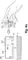
- Figs. 4a-d show an embodiment of the cannula insertion and cradle unit (20) adherence. Insertion of the tip (330) can be carried out manually (not shown in Figs. 4a-d ), or automatically with an insertion device (800), which is preloaded with a dedicated cannula cartridge unit (700). Fig.
- the cannula cartridge unit (700) includes a soft cannula (330) surrounded by penetrating member (702).
- the cannula has a grip portion (704), rubber septum (402), and cannula hub (401) for anchoring.
- the cannula cartridge unit (700) is enclosed within a protector (701) that maintains sterility, avoids unintentional pricking, and facilitates inserter loading.
- the cannula cartridge unit (700) is discussed in the co-owned/co-pending U.S. Provisional Patent Application No. 60/937,155 , and the insertion method is discussed in the co-owned/co-pending U.S. Provisional Patent Application No. 60/937,214 .
- the insertion device (800) includes a housing (804) in which the cradle (20) can be loaded.
- the housing has also a slot (806) into which the cannula cartridge unit (700) can be loaded, and a button (802) which initiates the insertion operation.
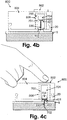
- Fig. 4b shows the insertion device (800) after it has been loaded with the cannula cartridge unit (700) and with the cradle unit (20) already adhered to the skin but the cannula (330) not yet inserted.
- Fig. 4c shows schematically the insertion of the cannula (330) into the patient's skin (5) by pressing the button (802).
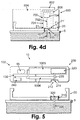
- Fig. 4d shows the retraction of the penetrating member (702) by gripping the grip portion (704).
- the cannula (330) is left positioned within the subcutaneous compartment.
- the cannula hub (401) is secured in the well by the anchors (21 and 21').
- Fig. 5 shows a cross-sectional view of the two-part patch unit (10) having a reusable part (100) and a disposable part (200).
- the patch unit (10) contains a dispensing apparatus (1005) and a monitoring apparatus (1006), each including at least one component residing within the disposable or the reusable parts.
- the reusable part (100) further includes electronics (130), which contains a processor-controller (not shown) and may include an energy supply (240).
- the disposable part (200) contains a reservoir (220), delivery tube (230), and outlet port (213), to which is connected the delivery tube (230). In some embodiments, the energy supply (240) can be provided in the disposable part (200).
- a connecting lumen (214) which is adapted to pierce the rubber septum (320) of the cannula (330) after connection of the patch unit (10) to the cradle unit (20).
- the distal end of the cannula (330) is seen being located within the subcutaneous tissue below the skin (5).
- the proximal end of the cannula is secured at the well (310).
- Manual operation buttons (15) may be provided on the housing of the reusable part (100).
- Figs. 6a-c show the connection of the patch unit (10) to the body via the cradle unit (20).
- Fig. 6a shows the cradle unit (20) being adhered to the skin of a user.
- Fig. 6b shows the connection of the patch unit (10) to the cradle unit (20).
- Fig. 6c shows the patch unit (10) after it has been connected to cradle unit (20).
- Figs. 7a-c show adhesion of the patch unit (10) directly to the body and not via the cradle unit (20). This embodiment does not form part of the invention.
- the adhesive is attached to the disposable part (200) and there is no cradle unit (20).
- Fig. 7a shows the peeling of the adhesive (101) from the bottom surface of the patch unit (10).
- Fig. 7b shows adhesive connection of the patch unit (10) to the skin.
- Fig. 7c shows the patch unit (10) after it has been connected to the user's body.
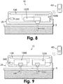
- Fig. 8 shows a patch unit (10) that is provided with a single tip (330).
- the patch unit (10) includes the dispensing apparatus (1005), the monitoring apparatus (1006), electronics (130), and an energy supply (240). All these components are disposed within a single unit which can be attached to the user's skin (5) either directly or via the cradle unit (20). Only this last embodiment, i.e. with a cradle unit, forms part of the invention.
- the remote control unit (40) may be used for remote or direct programming and/or data handling.
- the dispensed fluid is insulin
- the monitored analyte is glucose
- the subcutaneous compartment includes ISF.
- Insulin may be continuously (or in short intervals, such as every 3-10 minutes) dispensed into the subcutaneous compartment by the dispensing apparatus (1005) through the tip (330).
- Glucose levels can be measured continuously, or periodically in short intervals, by the monitoring apparatus (1006), using the tip (330).
- Fig. 9 shows another embodiment of the patch unit (10) which can be connected to the body via cradle unit (20).
- the cradle unit (20) is provided with two passageways, one for cannula (330) and the second for a probe (3330).
- the patch unit includes a dispensing apparatus (1005), a monitoring apparatus (1006), electronics (130), and an energy supply (240).
- the dispensing apparatus (1005) includes one or more components of an insulin pump (e.g .,, a reservoir, driving mechanism, and pumping mechanism).
- the dispensing apparatus (1005) also has an outlet port that can be connected to the cannula (330).
- the monitoring apparatus (1006) can include one or more components of a continuous glucose monitor, and it can be connected to a probe (3330).
- the remote control unit (40) may be used for remote programming and/or data handling of both the dispensing apparatus (1005) and monitoring apparatus (1006).
- the single patch unit (10) containing the dispensing apparatus (1005) and monitoring apparatus (1006) can be a single-part or a two-part (reusable and disposable) patch unit (10).
- the patch unit (10) can be contained in one or two housings. Further, the patch unit (10) can be operated by a remote control unit (40) and/or by manual buttons (not shown in Fig. 9 ) located on the patch housing.
- each one of the cannula (330) and probe (3330) can be similar to the tip (330) shown in Fig. 8 .
- Fig. 10a shows an embodiment of a one-part patch unit (10) that includes a monitoring apparatus (1006) and dispensing apparatus (1005) which employs a peristaltic pumping mechanism (116). Fluid is delivered from reservoir (220) through delivery tube (230) to the outlet port (213) by means of a peristaltic pumping mechanism (116). There is provided a sensing means (2000) situated near the outlet port (213) and having access to the interior of the delivery tube (230). The sensing means (2000) is electrically connected by wires (2100) to a processor-controller (2200). Subcutaneous analyte concentration levels are measured by the sensing means (2000) and signals are transported through wires (2100) to be analyzed by the processor-controller (2200).
- the pumping mechanism (116) can be activated by a driving mechanism (114).
- the driving mechanism (114), which actuates the pumping mechanism (116) can include without limitation a stepper motor, DC motor, or SMA actuator.
- An energy supply (240) can also be provided, which can be one or more batteries.
- the dispensing apparatus (1005) and the monitoring apparatus (1006) are configured to be controlled by a PCB having electronics (130), which may also contain the processor-controller (2200). Programming can be done by the remote control unit (40) and/or by at least one button (15) provided on the patch unit (10).
- Fig. 10b shows an embodiment of a two-part patch unit (10) that includes a monitoring apparatus (1006) and a dispensing apparatus (1005) which employs a peristaltic pumping mechanism (116).
- the two-part patch unit (10) includes a reusable part (100) and a disposable part (200), wherein each part can be contained in a separate housing.
- the reusable part (100) includes the relatively expensive components of the monitoring and dispensing apparatuses, including without limitation, a driving mechanism (114), a pumping mechanism (116), electronics (130), and a processor-controller (2200).
- At least one manual operating button (15) can be provided for operating the patch unit (10) and can be located on the reusable part (100).
- the disposable part (200) includes an outlet port (213) and relatively cheap components of the dispensing apparatus, including without limitation, a reservoir (220), a delivery tube (230), energy supply (240), and relatively cheap components of the monitoring apparatus (1006), including without limitation, wires (2100) and connectors (405).
- the monitoring apparatus' sensing means (2000) can be located within the disposable part (200) (extrinsic configuration) or on the tip (intrinsic configuration), as discussed below in connection with Figs. 20a and 20b , respectively.
- the energy supply (240) can be contained in the reusable part (100).
- Analyte monitoring and fluid dispensing can be done after connecting and pairing the reusable part (100) to the disposable part (200) and after connecting the two paired parts to the cradle unit (20) (not shown) and to the tip (330).
- a detailed discussion of the fluid dispensing can be found in the co-owned/co-pending U.S. Patent Application No. 11/397,115 and International Patent Application No. PCT/IL06/001276 .
- a detailed discussion of analyte monitoring can be found in the co-owned/co-pending U.S. Patent Application No. 11/706,606 , U.S. Provisional Patent Application No. 60/876,945 and International Patent Applications Nos. PCT/IL07/001096 and PCT/IL07/001177 .
- programming can be done by the remote control unit (40) and/or by at least one button (15) provided at the patch unit (10).
- the dispensing apparatus can include various types of pumping mechanisms (e.g ., peristaltic pump or plunger movement within a syringe) and various driving mechanisms (e.g ., DC or stepper motors, SMA derived motors, piezo, or bellow).
- the monitoring apparatus (1006) can include various types of monitoring mechanisms (e.g ., electrochemical, optical, acoustic, or any combination of known methods for analyte monitoring).
- Fig. 11a illustrates an embodiment of the one-part patch unit (10) that includes a monitoring apparatus and dispensing apparatus, which employs a plunger/piston pumping mechanism. Fluid is delivered from reservoir (220) to the outlet port (213) by means of a plunger/piston pumping mechanism (116). Sensing means (2000) is electrically connected by wires (2100) to processor-controller (2200). Subcutaneous analyte concentration levels are measured by the sensing means (2000) and signals are transported through wires (2100) to be analyzed by the processor-controller (2200). The pumping mechanism (116) can be actuated by driving mechanism (114).
- the driving mechanism (114), which actuates the pumping mechanism (116), can include without limitation, a stepper motor, DC motor, or SMA actuator.
- An energy supply (240) can also be provided, which can be one or more batteries.
- the dispensing apparatus and the monitoring apparatus are configured to be controlled by a PCB having electronics (130), which may contain processor-controller (2200). Programming can be done by the remote control unit (40) and/or by at least one button (15) provided at the patch unit (10).
- Fig. 11b illustrates an exemplary embodiment of a two-part patch unit (10) that includes a monitoring apparatus and dispensing apparatus, which employs a plunger/piston pumping mechanism (116).
- the two-part patch unit (10) includes a reusable part (100) and a disposable part (200), where each part can be contained in a separate housing.
- the reusable part (100) includes the relatively expensive components of the monitoring and dispensing apparatuses, which may include without limitation, a driving mechanism (114), pumping mechanism (116), electronics (130), and processor-controller (2200).
- At least one manual operating button (15) can be provided on the reusable part (100).
- the disposable part (200) includes outlet port (213), relatively cheap components of the dispensing apparatus, which may include without limitation, a reservoir (220), energy supply (240), and relatively cheap components of the monitoring apparatus, which may include wires (2100) and electrical connectors (405, 405').
- the monitoring apparatus sensing means (2000) can be located within the disposable part (200) (extrinsic configuration) or on the tip (intrinsic configuration) as will be detailed further, for example, in Figs. 20a and 20b , respectively.
- the energy supply (240) can be contained in the reusable part (100).
- Analyte monitoring and fluid dispensing can be done after connecting and pairing the reusable part (100) to the disposable part (200), connecting connectors (405,405'), and connecting the two paired parts to the cradle unit (20) (not shown) and tip (330).
- Figs. 12-14 illustrate an embodiment of the two-part patch unit (10), which includes a dispensing apparatus (1005) employing a piston-plunger pumping mechanism (116) and a monitoring apparatus (1006) employing an electrochemical sensing mechanism.
- the dispensing apparatus (1005) includes driving mechanism (114) and pumping mechanism (116), which are contained in the reusable part (100), and reservoir (220), delivery tube (230), energy supply (240) and the outlet port (not shown), which are contained in the disposable part (200).
- the electronic components (130) are located in the reusable part (100) and can be used both by the dispensing and monitoring apparatuses.
- Power is supplied to the reusable part (100) from the energy supply (240) located in the disposable part (200), by wires (2400) and connectors (410) that close the electrical circuit after pairing with the disposable part (200).
- the energy supply (240) can be located in the reusable part (100).
- the patch unit (10) is connectable to tip (330), which can be inserted in the subcutaneous tissue.
- the single tip (330) has electrodes (120, 121, 122) longitudinally deployed on its outer surface.
- One of the electrodes is a working electrode, the other is a counter electrode and the third electrode is a reference electrode.
- the monitoring apparatus (1006) includes sensing means (2000) having electrodes (120, 121, 122), wires (2100), connectors (405), and controller-processor (2200).
- At least the working electrode is coated by an enzyme-coated sensing layer. Upon contact of the enzyme-coated layer with the surrounding fluid which contains glucose, electrons are generated within the sensing layer by virtue of an enzyme-catalyzed electrochemical reaction.
- the electrons are transferred by the electrodes and wires (2100), through the connectors (405), to the processor-controller (2200) and are detected therein as an electrical signal, the intensity of which is proportional to the glucose concentration.
- the sensing means (2000) and the tip (330) can be deployed in the disposable part (200) and the processor-controller (2200) can be located in the reusable part (100).
- the electron-transferring wires and connectors can be embedded within the cradle unit (20) as will be further explained with reference to Fig. 26b .
- Figs. 12a-b shows an embodiment of a two-part patch unit (10) employing electrochemical-sensing when the electrodes are placed on the outer periphery of the tip (330).
- Fig. 12a shows a two-part patch unit (10) that is connected to cradle (20) which is adherable to the skin (5).
- the patch unit (10) includes the reusable part (100) and the disposable part (200).
- the monitoring apparatus (1006) includes processor-controller (2200) and connectors (405) in the reusable part (100), wiring (2100) and connectors (405) in the disposable part (200), and a tip (330) with electrodes (120, 121, and 122).
- the electrodes (120, 121, 122) extend along the entire or partial outer periphery of the tip (330).
- Fig. 12b shows a cross-sectional view of the tip (330) with longitudinal electrodes (120, 121, 122) on its outer periphery.
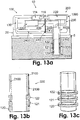
- Figs. 13a-c shows an embodiment of a two-part patch unit (10) employing electrochemical sensing, in which the electrodes are located on the outer periphery of the tip (330) transversally, in a concentric, ring-like, manner.
- Fig. 13a shows the two-part patch unit (10) that is connected to cradle unit (20) which is adherable to the skin (5).
- the patch unit (10) comprises reusable (100) and disposable (200) part.
- the monitoring apparatus (1006) includes processor-controller (2200) and connectors (405) in the reusable part (100), wiring (2100) and connectors (405) in the disposable part (200) and tip (330) with electrodes (120, 121, 122).
- the electrodes (120, 121, 122) are located on the outer periphery side of the tip (330) concentrically, in a ring-like manner.
- Figs. 13b and 13c show longitudinal cross-sectional and isometric views, respectively, of the tip (330) with ring-like electrodes (120, 121, 122) transversally located on its outer periphery, and the electrical current transfer wiring (2100).
- Fig. 14 shows a two-part patch unit (10) which includes the dispensing apparatus (1005) and the monitoring apparatus (1006), employing electrochemical monitoring.
- Fig. 14 shows the details of the monitoring apparatus (1006) within the reusable part (100) and disposable part (200).
- the patch unit (10) is connected to cradle unit (20) which is adherable to skin (5).
- the monitoring apparatus (1006) is shared between the reusable part (100) and disposable part (200) and employs an electrochemical sensing means (2000).
- the reusable part (100) includes processor-controller (2200) and an electric circuit (400).
- the circuit (400) contains necessary components to provide a potential or current to the electrodes for the electrochemical reaction that occurs on the electrodes, and to measure the electrical current or potential produced by the electrodes due to this electrochemical reaction.
- Wires (2100) and connectors (405) are provided to electrically connect between the disposable (200) and reusable (100) parts.
- the disposable part (200) is connected to a tip (330) which contains the sensing means (2000), located subcutaneously.
- the dispensing apparatus (1005) can also be contained within the reusable part (100) and the disposable part (200), where the reusable part (100) includes the driving mechanism (114) and pumping mechanism (116), and the disposable part (200) includes reservoir (220) and delivery tube (230).
- the reusable part (100) includes the driving mechanism (114) and pumping mechanism (116)
- the disposable part (200) includes reservoir (220) and delivery tube (230).
- Figs. 15-17 show embodiments of a two-part patch unit (10) which includes a dispensing apparatus (1005) employing a pumping mechanism (116) and a monitoring apparatus (1006) employing an optical sensing mechanism.
- the dispensing apparatus (1005) includes driving mechanism (114) and pumping mechanism (116), which are contained in the reusable part (100).
- the dispensing apparatus (1005) further includes reservoir (220), delivery tube (230), energy supply (240), and outlet port (not shown) contained in the disposable part (200).
- the electronics (130) and processor-controller (2200) are located in the reusable part (100) and can be used by both the dispensing apparatus (1005) and monitoring apparatus (1006).
- the energy supply (240) can be located in the reusable part (100).
- the monitoring apparatus (1006) in the shown embodiment includes at least one light-emitting source (101), at least one detector (102), and at least one optical deflecting means (109).
- the path of light propagating from the light-emitting source (101) into the body is shown as a solid line and the path of light propagating from the body to the detector (102) is shown as a dashed line.
- Emitted light (300) from the light-emitting source (101) is deflected by deflecting means (109) to the body and the returned light reaches the detector (102) and is analyzed by the processor-controller (2200).
- the light-emitting source (101), detector (102), and processor-controller (2200) can be located in the reusable part (100) and the deflecting means (109) can be located in the reusable part (100).
- Windows (111, 112) are provided in the reusable part (100) and disposable part (200). The windows (111, 112) are aligned and maintain passing of the light along the above paths after the reusable part (100) and disposable part (200) are paired.
- Fig. 15 shows the two-part patch unit (10), connected to a cradle unit (20) which is adherable to skin (5) and the components of the optical-based monitoring apparatus (1006) which is divided between the reusable part (100) and disposable part (200).
- Light emitted from the source (101) is deflected by the deflecting means (109) to a tip (330) and into the ISF of the subcutaneous tissue.
- Spectra of the emitted light can be varied depending on the measured analyte (13). For example, if the analyte is glucose, a spectra in the near-infrared (NIR), mid infrared, or visible light range can be used (altogether or separately).
- NIR near-infrared
- the light (300) propagating towards the tip's (330) distal end returns to the tip (330), and then, via the deflecting means (109), to the detector (102).
- the reflected light spectra are analyzed by the processor-controller (2200) to obtain analyte concentration levels.
- Embodiments of patch units (10) with various configurations for directing light from the light-emitting source (101) through the tip (330) to the body and then back to the detector (102), are discussed in U.S. Provisional Patent Application No. 61/004,039 .
- Figs. 16a-17c illustrate embodiments of the two-part patch unit (10) having a dispensing apparatus (1005) and a monitoring apparatus (1006).
- the dispensing apparatus (1005) includes the driving and pumping mechanisms (not shown in Figs. 16a-17c ) in the reusable part (100), and reservoir (220) and delivery tube (230) in the disposable part (200).
- the dispensing apparatus (1005) delivers fluid from the reservoir (220) through the delivery tube (230) via the pumping mechanism (not shown in Figs. 16a-17c ) through the tip (330) to the body.
- the monitoring apparatus (1006) contains light-emitting source (101) and detector (102) located in the reusable part (100), optical fiber (106) and lens (105) which can be located in the reusable part (100) or disposable part (200).
- Deflecting means (109) can include a reflecting mirror (108), which directs the light (300) to and from the body.
- an additional optical coupler (190) may be present between the reusable (100) and disposable (200) parts, and/or at the distal end of the tip (330).
- the optical coupler (190) may include without limitation a window inclined at a certain angle (e.g., 8 degrees) to ensure that reflected light is not coupled back from the tissue to the optical fiber (106).
- Figs. 16a-c show an embodiment of the two-part patch unit (10) comprising dispensing apparatus (1005) and monitoring apparatus (1006).
- the monitoring apparatus (1006) includes lens (105), for focusing the light (300) passing between the reusable part (100) and disposable part (200).
- the optical lens (105) serves as collimating means, or focusing means, for narrowing down the scattering of the emitted and returning light.
- the lens may be made from a variety of suitable materials, including without limitation, plastic, glass, or crystal. Use of a plastic lens may be more cost-effective; however, glass and crystal have superior optical properties.
- Fig. 16a and Fig. 16b show a side-view and a top-view, respectively, of the patch unit (10) with the lens (105) located between the reusable and disposable parts (100, 200).
- Fig. 16c shows an enlarge view of the contact surfaces between the reusable part (100) and disposable part (200) and the passage of light (300) between the two parts via the lens (105).
- Figs. 17a-c show a side-view ( Fig. 17a ) and a top-view ( Fig. 17b ) of the two-part patch unit (10) having a dispensing apparatus (1005) and a monitoring apparatus (1006).
- the light path through the monitoring apparatus (1006) includes two aligned optical windows (110, 111) located in the reusable part (100) and disposable part (200), respectively, and enabling passage of light (300) between the two parts.
- the optical windows (110, 111) serve as means for allowing the passage of light (300) between the reusable (100) and disposable (200) parts.
- the two windows (110, 111) may be, both or separately, inclined by for example, about an eight-degree angle to prevent backwards optical reflection into the optical fiber (106).
- the two optical windows (110, 111) are made of material, which is translucent to light in the wavelengths relevant for detecting analyte concentration levels, allowing for light to pass through the windows (110, 111).
- the windows (110, 111) can be made from a variety of suitable materials, including without limitation, plastic, glass, or crystal.
- the optical windows (110, 111) serve as focusing means, so that when the emitted or returned light passes through them, they narrow down any possible scattering of the light.
- the monitoring apparatus (1006) can use any one of the following optical means:
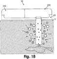
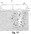
- Figs. 18-19 show embodiments of the two-part patch unit (10) having a reusable part (100) and a disposable part (200).
- the patch unit (10) is connected to cradle unit (20) which is adherable to the skin (5).
- the patch unit (10) contains dispensing and monitoring apparatuses (not shown in Figs. 18-19 ) that use tip (330).
- the tip (330) is semi-permeable or permeable, allowing for diffusion of analyte molecules into the tip (330) across its membrane wall.
- the dispensed fluid e.g ., insulin
- the dispensed fluid is used as a solution within the tip (330) into which molecules from the surrounding ISF can diffuse.
- Diffusion of analyte molecules across the semi-permeable or permeable membrane follows the direction of the concentration gradient.
- the analyte concentration within the tip (330) is proportional or equal to the analyte concentration in the surrounding ISF depending on the recovery time, which is defined as the time for achieving concentration equilibrium.
- Fig. 18 shows an embodiment of the patch unit (10) that is connected to the single subcutaneously insertable tip (330).
- the tip (330) includes a semi-permeable membrane allowing diffusion of low molecular weight molecules (13) (e.g ., glucose) while providing a barrier for high molecular weight molecules (14).
- low molecular weight molecules (13) e.g ., glucose
- Fig. 19 shows an embodiment in which the tip (330) includes a permeable membrane which is permeable for both small molecular weight molecules (13) and large molecular weight (14) molecules.
- the permeable tip can be cheaper and allows rapid recovery time but renders specific analyte (usually consisting of small molecular weight molecules) monitoring less accurate.
- the tip (330) that is used for monitoring analyte concentration levels and for delivering fluid is a microdialysis ("MD") or a microperfusion (“MP") probe, as known in the art.
- the probe may be perfused with the dispensed fluid (e.g., insulin), or with an additional/alternative perfusion fluid (e.g ., saline).
- the tip membrane may be either semi-permeable or permeable.
- MD probes are known in the art and examples of their description can be found in U.S. Patent No.
- Figs. 20a-b show embodiments of the tip (330), in which the MD tip ( Fig. 20a ) or the MP tip ( Fig. 20b ) is used and which is similar to MD or MP probes known by those of ordinary skill in the art, apart from the fact that it contains an opening at the bottom (331), or on its side (332), allowing for fluid entering the tip (33) to be delivered via the tip (330) from the patch unit (10) to the user's body.
- the tip (330) in this embodiment serves both as a means for dispensing fluid into the body and as a MD or MP probe for monitoring analyte concentrations.
- the analyte sensing means can be configured in one of the following configurations:
- Analyte sensing means can be based on electrochemical, optical, acoustic, or any other analyte sensing means known by those of ordinary skill in the art.
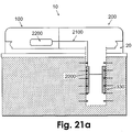
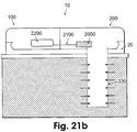
- Figs. 21a-b show a two-part patch unit (10) having reusable (100) and disposable (200) parts.
- the patch unit (10) contains a dispensing apparatus and a electrochemical monitoring apparatus, and is connected to a cradle unit (20).
- the patch unit (10) can be connected to tip (330) having a membrane which is semi-permeable or permeable.
- the monitoring apparatus is provided with sensing means (2000).
- Figs. 21a and 21b show two configurations of the sensing means (2000) within the tip (i.e., intrinsic) ( Fig. 21a ) and within the patch (i.e., extrinsic) ( Fig. 21b ).
- Fig. 21a shows an embodiment of a two-part patch unit (10) that includes dispensing and monitoring apparatuses (not shown in Figs. 21a-b ), which employs an intrinsic sensing means (2000).
- the patch unit (10) is connected to cradle (20) that is adherable to skin (5).
- the monitoring apparatus includes processor-controller (2200) located in the reusable part (100), wires (2100) located in reusable and disposable parts (100 and 200), and tip (330) with sensing means (2000).
- the sensing means (2000) is located within the tip (330) (intrinsic configuration).
- the tip (330) has a permeable or semi-permeable membrane that allows analyte to diffuse in the direction of the concentration gradient (illustrated by arrows).
- Fig. 21b shows an embodiment of a two-part patch unit (10) that includes dispensing and monitoring apparatuses (not shown in Fig. 21b ) which employs an extrinsic sensing means.
- the patch unit (10) is connected to cradle unit (20) that is adherable to skin (5).
- the monitoring apparatus includes processor-controller (2200) located in the reusable part (100), wires (2100) located in the disposable part (200), and tip (330).
- the sensing means (2000) is located within the patch (10), preferably in the disposable part (200) (extrinsic configuration).
- the tip (330) has permeable or semi-permeable membrane that allows analyte molecules to diffuse in the direction of the concentration gradient (shown by arrows).
- the dispensing apparatus contains means (not shown) for transferring analyte-rich fluid from the tip (330) into the patch unit (10).
- One method of such transfer includes reversing the direction of fluid delivery, as disclosed in the co-owned, co-pending International Patent Application No. PCT/US08/062928 and U.S. Patent Application No. 12/116,546 , both of which claim priority to U.S. Provisional Patent Application No. 60/928,054 .
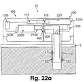
- Figs. 22a-c and 23 show embodiments of a two-part patch unit (10) that includes a dispensing apparatus (1005) and an electrochemical monitoring apparatus (1006).
- the patch unit (10) includes a reusable part (100) and a disposable part (200) and is connected to cradle unit (20), which is adherable to the skin (5).
- the dispensing apparatus (1005) includes processor-controller (2200), driving mechanism (114) and pumping mechanism (116), located in the reusable part (100), and reservoir (220) and delivery tube (230), located in the disposable part (200).
- the monitoring apparatus (1006) includes the processor-controller (2200) located in the reusable part (100), wires (2100), connectors (405), and electrochemical sensing means, which can be intrinsic or extrinsic.
- Fig. 22a shows an exemplary embodiment of an electrochemical-based monitoring apparatus (1006) that contains an intrinsic configuration of a sensing means.
- the sensing means is located on the tip (330) in the subcutaneous compartment and includes a working electrode (120), counter electrode (121), and reference electrode (122).
- the electrodes can be located longitudinally on the outer or inner side of the tip. Current is transferred from electrodes by wires (2100) and connectors (405) to the processor-controller (2200).
- Figs. 22b and 22c show a transverse cross-sectional view ( Fig. 22b ) and isometric view ( Fig. 22c ) of concentrically, ring-like, electrodes (120, 121, 122) located transversally on the inner side of the tip (330).
- the tip (330) is either permeable or semi-permeable.
- the electrodes can be located on the outer side of the tip (330).
- the tip (330) may be circular, oval, rectangular, have a flat outer contour, or any other shape.
- the tip (330) may be non-permeable or semi-permeable and the electrodes can be located on the outer or inner surface of the tip (330).
- Fig. 23 shows an embodiment of an electrochemical-based monitoring apparatus (1006) that contains extrinsic sensing means.
- Sensing means (2000) is located on the tip (330) within the patch unit (10) and can include at least one working electrode (120), counter electrode (121) or reference electrode (122).
- the electrodes can be located on the outer or inner surface of the tip (330).
- Current is transfer from electrodes by wires (2100) and connectors (405) to the processor-controller (2200).
- Analyte-rich solution from the subcutaneous tip portion can reach the sensing means (proximal end of the tip) by diffusion along the tip (following the concentration gradient within the tip) or by forcible fluid transfer (e.g ., due to reverse flow of the fluid within the tip created by reversing the pumping mechanism direction).
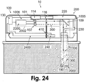
- Figs. 24-25 show embodiments of a two-part patch unit (10) that includes a dispensing apparatus (1005) and an optical-based monitoring apparatus (1006).
- the patch unit (10) includes reusable part (100) and disposable part (200) and is connected to cradle unit (20), which is adherable to the skin (5).
- the dispensing apparatus (1005) includes processor-controller (2200), driving mechanism (114) and pumping mechanism (116) located in the reusable part (100), and reservoir (220) and delivery tube (230) located in the disposable part (200).
- the monitoring apparatus (1006) includes light-emitting source (101), detector (102), and processor-controller (2200), located in the reusable part (100), wires (2100) and connectors (405) located in both parts.
- the tip (330) can be permeable or semi-permeable.
- the optical sensing means can be either intrinsic ( Fig. 24 ) or extrinsic ( Fig. 25 ).
- Optical means e.g., windows, lens, may be deployed between the reusable (100) and disposable (200) parts for more efficient passage of light (300) between the two parts.
- Fig. 24 shows an embodiment of two-part patch unit (10) that includes a dispensing apparatus (1005) and monitoring apparatus (1006).
- the dispensing apparatus (1005) includes processor-controller (2200), driving mechanism (114) and pumping mechanism (116) located in the reusable part (100), and reservoir (220) and delivery tube (230) located in the disposable part (200).
- the optical-based monitoring apparatus (1006) contains an intrinsic sensing means (2002).
- the sensing mechanism including the light-emitting source (101) and detector (102), is located within the patch unit (10), and the sensing means (2000) is located in the tip (330).
- the sensing means (2000) resides in the subcutaneous compartment and includes at least one reflecting mirror (190).
- Direction (300) of light emitted from the source (101) is deflected by deflecting means (109) into tip (330) and the light is reflected by mirror (190) towards the deflecting means (109) and detector (102), to be analyzed by the processor-controller (2200).
- the tip (330) can be permeable or semi-permeable, thus the analyte of interest (i.e., glucose) can flow in the direction of the concentration gradient.
- Optical spectral analysis can be achieved when light passes through the analyte-rich solution within the tip (330).
- Fig. 25 shows an embodiment of a two-part patch unit (10) that includes a dispensing apparatus (1005) and a monitoring apparatus (1006).
- the dispensing apparatus (1005) includes processor-controller (2200), driving mechanism (114) and pumping mechanism (116), located in the reusable part (100), and reservoir (220) and delivery tube (230), located in the disposable part (200).
- the optical-based monitoring apparatus (1006) contains an extrinsic sensing means. Some elements of the sensing means, including the light-emitting source (101) and detector (102) are located within the patch unit (10).
- Direction (300) of light (300) emitted from source (101) is directed towards the analyte-rich fluid, and is reflected by mirror (109) back to detector (102), to be analyzed by the processor-controller (2200).
- the tip (330) can be permeable or semi-permeable, thus the analyte of interest (e.g ., glucose) can flow in direction of the concentration gradient.
- Optical spectral analysis can be achieved when light passes through the analyte-rich solution within the tip (330).
- Analyte-rich solution from the subcutaneous tip portion can reach the sensing means within the patch unit (10) for sensing (proximal end of cannula) either by diffusion along the tip (330) (following the concentration gradient) or by active fluid transfer (e.g ., due to backward flow of the fluid within the tip created by reversing the direction of movement of the pumping mechanism).
- Fig. 26a shows an embodiment of a patch unit (10) that contains a dispensing apparatus and monitoring apparatus.
- the monitoring apparatus contains an extrinsic sensing means (2000) wired to a processor-controller (2200) connected to the electronic components (130).
- the dispensing apparatus employs driving mechanism (114) and a peristaltic pumping mechanism composed of a rotary wheel (112), which dispenses fluid in the direction of rotation (clockwise or counter clockwise) from the reservoir (220) via a delivery tube (230). Accordingly, flow can be delivered forward (from patch unit (10) to tip (330)) and backward (form tip (330) to patch unit (10)).
- the monitoring apparatus can employ electrochemical or optical sensing.
- analyte-rich fluid from the distal end of the tip (330) to the proximal end within the patch unit (10) brings to the sensing means (2000) within the patch unit (10) a solution which contains analyte concentration identical (or at a known ratio) to that in the ISF.
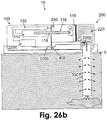
- Fig. 26b shows an embodiment of a patch unit (10) that contains both dispensing and monitoring apparatuses.
- the monitoring apparatus contains extrinsic sensing means (2000) wired via connectors (410) to processor-controller (2200) connected to the electronics (130) residing in the reusable part (100).
- the dispensing apparatus employs, for example, a syringe type pumping mechanism (116).
- the driving mechanism (114) can push or pull the piston rod (118) which is paired with a plunger (119). Accordingly, flow can be delivered forward via the reservoir (220) in the disposable part (200) (from patch unit (10) to tip (330)) and backward (from tip (330) to patch unit (10)).
- analyte-rich fluid from the distal end of the tip (330) to the proximal end within the patch unit (10) brings to the sensing means (2000) within the patch unit (10) a solution which contains analyte concentration identical (or at a known ratio) to that in the ISF.
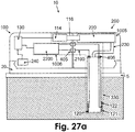
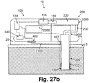
- Figs. 27a-b shows embodiments of the patch unit (10) having dispensing and monitoring apparatuses and configurations of electrical wires (2100).
- the monitoring apparatus (1006) includes intrinsic electrochemical sensing means.
- the dispensing apparatus (1005) includes electronics (130), processor-controller (2200), driving mechanism (114) and pumping mechanism (116), located in the reusable part (100), and reservoir (220) and delivery tube (230), located in the disposable part (200).
- electrical current generated on the electrodes (120, 121, 122) are delivered by wires (2100) to a set of contacts (406) at the proximal end of the tip (330).
- a set of contacts (405) transfer the electrical current from the disposable part (200) to the reusable part (100) and to the processor-controller (2200).
- electrical current generated on the electrodes (120, 121, and 122) are delivered by wires (2100) to a set of contacts (407) at the proximal end of the tip (330).
- An additional set of contacts (408) transfer the electrical current from the cradle unit (20) to the reusable part (100) and to the processor-controller (2200).
- Fig. 28 shows one embodiment of the device that includes patch unit (10) and can include remote control unit (40).
- the patch unit (10) can be connected to cradle unit (20) and to tip (330).
- the patch unit (10) contains dispensing apparatus (1005) and monitoring apparatus (1006).
- the dispensing apparatus delivers fluid according to analyte concentration levels that are monitored by the monitoring apparatus (1006).
- the device can function as a closed loop or semi-closed loop system.
- the patch unit (10) can include two parts -- reusable part (100) and disposable part (200) -- and can include buttons for inputting flow programs.
- additional inputs from the user e.g ., meal times, changes in basal insulin delivery rates, or boluses before meals
- additional inputs from the user e.g ., meal times, changes in basal insulin delivery rates, or boluses before meals
- User inputs can be done with the remote control unit (40) or with the buttons (not shown) on the patch unit (10).
- the patch unit (10) may be connected to a remote control unit (40) that controls the patch unit (10), where the remote control unit (40) further includes a blood glucose monitoring component that allows monitoring and controlling blood glucose levels in the body of the patient.
- the patch unit (10) may include a dual-purpose tip (330) and can be a one-part or a two-part patch unit. Further, the patch unit (10) is capable of being connected and disconnected to the cradle unit (20), which can be adhered to the skin of the patient and accommodate insertion of the tip (330).
Landscapes
- Health & Medical Sciences (AREA)
- Life Sciences & Earth Sciences (AREA)
- Hematology (AREA)
- Engineering & Computer Science (AREA)
- Anesthesiology (AREA)
- Animal Behavior & Ethology (AREA)
- Heart & Thoracic Surgery (AREA)
- Vascular Medicine (AREA)
- Veterinary Medicine (AREA)
- Biomedical Technology (AREA)
- General Health & Medical Sciences (AREA)
- Public Health (AREA)
- Dermatology (AREA)
- Diabetes (AREA)
- Measurement Of The Respiration, Hearing Ability, Form, And Blood Characteristics Of Living Organisms (AREA)
- Infusion, Injection, And Reservoir Apparatuses (AREA)
- Measuring And Recording Apparatus For Diagnosis (AREA)
Claims (15)
- Dispositif pouvant adhérer à la peau destiné à délivrer un fluide thérapeutique dans le corps d'un patient, comprenant :(i) un embout (330) destiné à délivrer le fluide thérapeutique dans le corps du patient et à surveiller un analyte corporel du corps du patient ;(ii) une unité timbre (10) comprenant :un appareil de surveillance (1006) comprenant un moyen de détection (2000) ;un appareil de distribution (1005) ;un processeur (130), (2200) destiné à commander une mise en oeuvre d'au moins l'un de l'appareil de surveillance (1006) et de l'appareil de distribution (1005) ; etun réservoir (220) pourvu d'un orifice de sortie (213) ; et caractérisé par(iii) une unité berceau pouvant adhérer à la peau (20) à laquelle l'unité timbre (10) peut être connectée et déconnectée, l'unité berceau pouvant adhérer à la peau (20) comprenant un passage (310) d'introduction de l'embout (330) et au moins un connecteur permettant de connecter l'unité timbre (10) à l'unité berceau pouvant adhérer à la peau (20), l'orifice de sortie (213) du réservoir permettant une communication fluidique entre le réservoir (220) et l'embout (330) lorsque l'unité timbre (10) est connectée à l'unité berceau pouvant adhérer à la peau (20) ;
et en ce que l'appareil de surveillance (1006) comprend en outre des fils de connexion (2100) conçus pour établir une communication électrique entre l'embout (330) et le processeur (2200). - Dispositif selon la revendication 1,
dans lequel ledit dispositif comprend en outre une partie réutilisable (100) et une partie jetable (200). - Dispositif selon la revendication 1, dans lequel le fluide thérapeutique est de l'insuline et l'analyte corporel est du glucose.
- Dispositif selon la revendication 1, dans lequel l'appareil de distribution comprend un mécanisme d'entraînement (114) et un mécanisme de pompage (116).
- Dispositif selon la revendication 4, dans lequel ledit appareil de distribution (1005) délivre de façon continue le fluide thérapeutique dans le corps du patient et ledit appareil de surveillance (1006) surveille de façon continue des analytes corporels du patient.
- Dispositif selon la revendication 1, dans lequel le dispositif fonctionne comme un dispositif à boucle fermée ou comme un dispositif à boucle semi-fermée.
- Dispositif selon la revendication 1, dans lequel ledit moyen de détection (2000) est un moyen optique ou électrochimique.
- Dispositif selon la revendication 2, dans lequel :ladite partie réutilisable (100) comprend de l'électronique incluant un processeur destiné à surveiller des fonctions du dispositif ;une source d'alimentation électrique (240) est disposée dans l'une ou l'autre de la partie réutilisable (100) et de la partie jetable (200), ou dans ces deux dernières, etladite partie jetable (200) comprend :le réservoir (220) contenant le fluide thérapeutique ;l'orifice de sortie (213) comportant une lumière de connexion conçue pour percer un septum en caoutchouc dudit embout (330) postérieurement à la connexion dudit embout (330) avec ledit dispositif.
- Dispositif selon la revendication 1, dans lequel ledit embout (330) est un embout unique pouvant être inséré de manière sous-cutanée, l'embout assurant des fonctions de sonde permettant de surveiller des taux d'analytes à l'intérieur du corps et de canule à travers laquelle du fluide est délivré au corps.
- Dispositif selon la revendication 1, dans lequel le moyen de détection (2000) est situé sur l'embout (330) dans un compartiment sous-cutané et comprend des électrodes, les électrodes comprenant une électrode de travail (120), une contre-électrode (121) et une électrode de référence (122).
- Dispositif selon la revendication 10, dans lequel les électrodes (120, 121, 122) sont situées longitudinalement sur l'un ou l'autre d'un côté extérieur et d'un côté intérieur de l'embout.
- Dispositif selon la revendication 10, dans lequel du courant électrique généré sur les électrodes (120, 121, 122) est appliqué par des fils (2100) à un ensemble de contacts (407) situés au niveau d'une extrémité proximale de l'embout, et un ensemble supplémentaire de contacts (408) transfère le courant électrique de l'unité berceau (20) à la partie réutilisable et au processeur.
- Dispositif selon la revendication 12, dans lequel ledit ensemble supplémentaire de contacts est intégré à l'intérieur de l'unité berceau.
- Dispositif selon la revendication 8, dans lequel :ladite partie réutilisable (100) et ladite partie jetable (200) sont conçues de façon à être connectées l'une à l'autre avant la mise en oeuvre de l'unité timbre ;la connexion de l'unité timbre (10) à l'unité berceau (20) établissant une communication fluidique entre le réservoir (220) situé dans la partie jetable (200) et l'embout (330), etune connexion électrique entre l'embout (330) et la partie jetable (200).
- Dispositif selon la revendication 10, dans lequel le courant électrique généré sur les électrodes (120, 121, 122) disposées sur l'embout est appliqué par les fils de connexion à un ensemble de contacts (406) au niveau de l'extrémité proximale de l'embout (330), et un ensemble supplémentaire de contacts (405) transfère le courant électrique de la partie jetable (200) à la partie réutilisable (100) et au processeur (2200).
Applications Claiming Priority (2)
| Application Number | Priority Date | Filing Date | Title |
|---|---|---|---|
| US404707P | 2007-11-21 | 2007-11-21 | |
| PCT/IL2008/001521 WO2009066288A1 (fr) | 2007-11-21 | 2008-11-20 | Système de surveillance d'analyte et de distribution de fluide |
Publications (2)
| Publication Number | Publication Date |
|---|---|
| EP2224977A1 EP2224977A1 (fr) | 2010-09-08 |
| EP2224977B1 true EP2224977B1 (fr) | 2017-07-05 |
Family
ID=40329047
Family Applications (1)
| Application Number | Title | Priority Date | Filing Date |
|---|---|---|---|
| EP08851596.0A Active EP2224977B1 (fr) | 2007-11-21 | 2008-11-20 | Système de surveillance d'analyte et de distribution de fluide |
Country Status (7)
| Country | Link |
|---|---|
| US (2) | US20100256593A1 (fr) |
| EP (1) | EP2224977B1 (fr) |
| JP (1) | JP2011504129A (fr) |
| CN (1) | CN101925372B (fr) |
| AU (1) | AU2008327483A1 (fr) |
| DK (1) | DK2224977T3 (fr) |
| WO (1) | WO2009066288A1 (fr) |
Families Citing this family (102)
| Publication number | Priority date | Publication date | Assignee | Title |
|---|---|---|---|---|
| US6850788B2 (en) | 2002-03-25 | 2005-02-01 | Masimo Corporation | Physiological measurement communications adapter |
| EP1987761B1 (fr) * | 2007-05-03 | 2019-10-23 | F. Hoffmann-La Roche AG | Capteur tubulaire destiné à la détection d'un analyte |
| US8480649B2 (en) * | 2008-04-29 | 2013-07-09 | Ofer Yodfat | Method for selecting bolus doses and bolus delivery patterns in a drug delivery device |
| US9138531B2 (en) | 2008-05-29 | 2015-09-22 | Roche Diagnostics Operations, Inc. | Device, a system and a method for identification/authentication of parts of a medical device |
| US7959598B2 (en) | 2008-08-20 | 2011-06-14 | Asante Solutions, Inc. | Infusion pump systems and methods |
| EP2334234A4 (fr) | 2008-09-19 | 2013-03-20 | Tandem Diabetes Care Inc | Dispositif de mesure de la concentration d'un soluté et procédés associés |
| WO2010044088A1 (fr) | 2008-10-16 | 2010-04-22 | Medingo Ltd. | Procédé et système permettant de réaliser une transmission adaptative de communications |
| US9597451B2 (en) | 2009-02-13 | 2017-03-21 | Roche Diagnostic Operations, Inc. | Insulin delivery safety |
| US20100286600A1 (en) * | 2009-05-08 | 2010-11-11 | Bommannan D Bommi | Transdermal patch device |
| WO2010150257A2 (fr) | 2009-06-25 | 2010-12-29 | Medingo Ltd. | Méthode et dispositif utilisés pour améliorer le contrôle de la glycémie daprès linsuline résiduelle |
| JP2011019563A (ja) * | 2009-07-13 | 2011-02-03 | Misuzu Kogyo:Kk | 薬液投与装置 |
| US8882710B2 (en) | 2009-09-02 | 2014-11-11 | Medtronic Minimed, Inc. | Insertion device systems and methods |
| US8900190B2 (en) | 2009-09-02 | 2014-12-02 | Medtronic Minimed, Inc. | Insertion device systems and methods |
| DK2475356T3 (da) | 2009-09-08 | 2019-06-17 | Hoffmann La Roche | Anordninger, systemer og fremgangsmåder til justering af fluidtilførselsparametre |
| AU2010296886A1 (en) | 2009-09-18 | 2012-04-12 | F.Hoffmann-La Roche Ag | Devices, systems and methods for quantifying bolus doses according to user parameters |
| US8998840B2 (en) | 2009-12-30 | 2015-04-07 | Medtronic Minimed, Inc. | Connection and alignment systems and methods |
| US9039653B2 (en) | 2009-12-29 | 2015-05-26 | Medtronic Minimed, Inc. | Retention systems and methods |
| US8998858B2 (en) | 2009-12-29 | 2015-04-07 | Medtronic Minimed, Inc. | Alignment and connection systems and methods |
| US8858500B2 (en) | 2009-12-30 | 2014-10-14 | Medtronic Minimed, Inc. | Engagement and sensing systems and methods |
| US9421321B2 (en) | 2009-12-30 | 2016-08-23 | Medtronic Minimed, Inc. | Connection and alignment systems and methods |
| US20120215163A1 (en) | 2009-12-30 | 2012-08-23 | Medtronic Minimed, Inc. | Sensing systems and methods |
| US11497850B2 (en) | 2009-12-30 | 2022-11-15 | Medtronic Minimed, Inc. | Connection and alignment detection systems and methods |
| US8435209B2 (en) | 2009-12-30 | 2013-05-07 | Medtronic Minimed, Inc. | Connection and alignment detection systems and methods |
| ES2704845T3 (es) | 2010-01-20 | 2019-03-20 | Hoffmann La Roche | Método y dispositivo para mejorar el control glucémico |
| DE102010014703A1 (de) * | 2010-04-12 | 2011-10-13 | Mbr Optical Systems Gmbh & Co. Kg | Medizinisches Gerätesystem |
| US8206340B2 (en) | 2010-08-18 | 2012-06-26 | Thuban, Inc. | Integrated glucose monitor and insulin injection pen with automatic emergency notification |
| US8915879B2 (en) | 2010-09-24 | 2014-12-23 | Perqflo, Llc | Infusion pumps |
| US9216249B2 (en) | 2010-09-24 | 2015-12-22 | Perqflo, Llc | Infusion pumps |
| US8777901B2 (en) | 2010-09-24 | 2014-07-15 | Perqflo, Llc | Infusion pumps |
| US9498573B2 (en) | 2010-09-24 | 2016-11-22 | Perqflo, Llc | Infusion pumps |
| EP2436311A1 (fr) * | 2010-10-04 | 2012-04-04 | PharmaSens AG | Dispositif de diagnostic |
| US8905972B2 (en) | 2010-11-20 | 2014-12-09 | Perqflo, Llc | Infusion pumps |
| EP2694135B1 (fr) * | 2011-04-05 | 2021-06-16 | PharmaSens AG | Dispositif appliqué par voie dermique pour accès intraveineux |
| EP2753380B1 (fr) * | 2011-09-05 | 2020-05-06 | Roche Diabetes Care GmbH | Dispositif d'injection portatif et module jetable |
| JP6120257B2 (ja) * | 2011-09-21 | 2017-04-26 | 国立大学法人東北大学 | 皮膚穿刺用針状デバイス、生体成分回収用デバイスおよび生体成分測定システム |
| GB201117539D0 (en) * | 2011-10-11 | 2011-11-23 | Univ Graz Med | Medical apparatus having infusion and detection capabilities |
| US8790307B2 (en) | 2011-12-01 | 2014-07-29 | Picolife Technologies, Llc | Drug delivery device and methods therefor |
| US8771229B2 (en) | 2011-12-01 | 2014-07-08 | Picolife Technologies, Llc | Cartridge system for delivery of medicament |
| US10130759B2 (en) | 2012-03-09 | 2018-11-20 | Picolife Technologies, Llc | Multi-ported drug delivery device having multi-reservoir cartridge system |
| US9883834B2 (en) | 2012-04-16 | 2018-02-06 | Farid Amirouche | Medication delivery device with multi-reservoir cartridge system and related methods of use |
| US10245420B2 (en) | 2012-06-26 | 2019-04-02 | PicoLife Technologies | Medicament distribution systems and related methods of use |
| WO2014045448A1 (fr) * | 2012-09-24 | 2014-03-27 | テルモ株式会社 | Dispositif d'insertion de capteur et procédé d'insertion de capteur |
| US10318915B2 (en) | 2012-09-26 | 2019-06-11 | Thuban, Inc. | Healthcare system for recording and monitoring transactions of system participants |
| US20140155819A1 (en) * | 2012-12-03 | 2014-06-05 | PicoLife Technologies | Medicament Delivery Systems |
| CN103110460B (zh) * | 2013-01-22 | 2015-02-18 | 苏波 | 检测治疗装置及远程监护鞋 |
| ES2651267T3 (es) * | 2013-02-06 | 2018-01-25 | Medirio Sa | Sistema para tratamiento médico |
| US9357961B2 (en) | 2013-02-22 | 2016-06-07 | Thuban, Inc. | Device for enabling patient self testing and treatment self- administration and system using the device for managing the patient's health care |
| CA2906135A1 (fr) * | 2013-03-15 | 2014-09-18 | Prometheon Pharma, Llc | Dispositifs, systemes et methodes d'administration transdermique de composes |
| US10517516B2 (en) * | 2013-05-02 | 2019-12-31 | Atonarp Inc. | Monitor and system for monitoring an organism |
| US9561324B2 (en) | 2013-07-19 | 2017-02-07 | Bigfoot Biomedical, Inc. | Infusion pump system and method |
| CN105658260A (zh) * | 2013-08-22 | 2016-06-08 | 交叉合作公司 | 用于监测造影剂的总递送剂量的方法和设备 |
| JP6213987B2 (ja) * | 2013-09-19 | 2017-10-18 | 国立研究開発法人産業技術総合研究所 | マイクログルコースセンサ |
| CN104622480B (zh) * | 2013-11-12 | 2017-12-05 | 上海移宇科技股份有限公司 | 单针集成型人工胰腺 |
| WO2015116067A1 (fr) * | 2014-01-29 | 2015-08-06 | Reaston Mary | Système et procédé pour établir une connexion sans fil |
| GB2523989B (en) | 2014-01-30 | 2020-07-29 | Insulet Netherlands B V | Therapeutic product delivery system and method of pairing |
| WO2016054079A1 (fr) | 2014-09-29 | 2016-04-07 | Zyomed Corp. | Systèmes et procédés pour la détection et la mesure du glucose sanguin du sang et d'autres analytes à l'aide du calcul de collision |
| US10159786B2 (en) | 2014-09-30 | 2018-12-25 | Perqflo, Llc | Hybrid ambulatory infusion pumps |
| US10598624B2 (en) | 2014-10-23 | 2020-03-24 | Abbott Diabetes Care Inc. | Electrodes having at least one sensing structure and methods for making and using the same |
| EP3236850A4 (fr) * | 2014-12-23 | 2018-07-18 | Ent. Services Development Corporation LP | Détection d'exposition à un allergène |
| CN111905188B (zh) | 2015-02-18 | 2022-07-22 | 英赛罗公司 | 流体输送和输注装置及其使用方法 |
| EP3650060B1 (fr) | 2015-02-18 | 2021-09-29 | Medtronic Minimed, Inc. | Pompes de perfusion ambulatoire et ensembles réservoirs destinés à être utilisés avec celles-ci |
| EP4378389A3 (fr) * | 2015-05-22 | 2024-08-07 | Dexcom, Inc. | Aiguille pour l'administration transcutanee de detecteurs d'analytes |
| US10780222B2 (en) * | 2015-06-03 | 2020-09-22 | Pacific Diabetes Technologies Inc | Measurement of glucose in an insulin delivery catheter by minimizing the adverse effects of insulin preservatives |
| US11065381B2 (en) | 2015-10-05 | 2021-07-20 | E3D A.C.A.L. | Infusion pump device and method for use thereof |
| CN112933333B (zh) | 2016-01-14 | 2023-03-28 | 比格福特生物医药公司 | 调整胰岛素输送速率 |
| EP3413954A1 (fr) | 2016-02-12 | 2018-12-19 | Perqflo, LLC | Pompes à perfusion ambulatoires et ensembles à utiliser avec celle-ci |
| EP3416705B1 (fr) * | 2016-02-19 | 2020-09-02 | Flextronics AP, LLC | Dispositif d'injection automatique avec actionnement magnétique |
| US10967118B2 (en) | 2016-02-19 | 2021-04-06 | Flex, Ltd. | Automatic injection device having a magnetic drive system |
| US9554738B1 (en) | 2016-03-30 | 2017-01-31 | Zyomed Corp. | Spectroscopic tomography systems and methods for noninvasive detection and measurement of analytes using collision computing |
| WO2018058041A1 (fr) | 2016-09-23 | 2018-03-29 | Insulet Corporation | Dispositif d'administration de fluide avec capteur |
| CN109922716A (zh) | 2016-12-12 | 2019-06-21 | 比格福特生物医药公司 | 药物输送设备的警报和警惕以及相关的系统和方法 |
| US11027063B2 (en) | 2017-01-13 | 2021-06-08 | Bigfoot Biomedical, Inc. | Insulin delivery methods, systems and devices |
| WO2018132754A1 (fr) | 2017-01-13 | 2018-07-19 | Mazlish Bryan | Système et procédé d'ajustement d'administration d'insuline |
| CN110461217B (zh) * | 2017-01-23 | 2022-09-16 | 雅培糖尿病护理公司 | 用于分析物传感器插入的系统、装置和方法 |
| SE541788C2 (en) * | 2017-12-22 | 2019-12-17 | Brighter Ab Publ | Skin patch for diagnosis comprising an evaporation layer |
| CN108245742A (zh) * | 2018-01-19 | 2018-07-06 | 苏州英诺迈医学科技服务有限公司 | 一种胰岛素注射装置 |
| USD928199S1 (en) | 2018-04-02 | 2021-08-17 | Bigfoot Biomedical, Inc. | Medication delivery device with icons |
| EP3788628A1 (fr) | 2018-05-04 | 2021-03-10 | Insulet Corporation | Contraintes de sécurité pour un système d'administration de médicament basé sur un algorithme de commande |
| US20210259634A1 (en) * | 2018-06-15 | 2021-08-26 | Otsuka America Pharmaceutical, Inc. | Re-wearable physiological monitoring device |
| GB201814644D0 (en) | 2018-09-10 | 2018-10-24 | Hilton Eric | Analysis and dispensing system |
| CN112789070A (zh) | 2018-09-28 | 2021-05-11 | 英赛罗公司 | 人造胰腺系统的活动模式 |
| WO2020077223A1 (fr) | 2018-10-11 | 2020-04-16 | Insulet Corporation | Détection d'événement pour système d'administration de médicament |
| USD920343S1 (en) | 2019-01-09 | 2021-05-25 | Bigfoot Biomedical, Inc. | Display screen or portion thereof with graphical user interface associated with insulin delivery |
| WO2021012075A1 (fr) * | 2019-07-19 | 2021-01-28 | Medtrum Technologies Inc. | Dispositif de perfusion de médicament intégré |
| EP4017357A4 (fr) * | 2019-08-19 | 2023-04-19 | Medtrum Technologies Inc. | Dispositif de détection |
| US11801344B2 (en) | 2019-09-13 | 2023-10-31 | Insulet Corporation | Blood glucose rate of change modulation of meal and correction insulin bolus quantity |
| US11935637B2 (en) | 2019-09-27 | 2024-03-19 | Insulet Corporation | Onboarding and total daily insulin adaptivity |
| EP4354455A3 (fr) | 2019-12-06 | 2024-07-10 | Insulet Corporation | Techniques et dispositifs fournissant une adaptivité et une personnalisation dans le traitement du diabète |
| US11833329B2 (en) | 2019-12-20 | 2023-12-05 | Insulet Corporation | Techniques for improved automatic drug delivery performance using delivery tendencies from past delivery history and use patterns |
| EP4088286A1 (fr) | 2020-01-06 | 2022-11-16 | Insulet Corporation | Prédiction d'événements de repas et/ou d'exercice sur la base de résidus persistants |
| US11551802B2 (en) | 2020-02-11 | 2023-01-10 | Insulet Corporation | Early meal detection and calorie intake detection |
| US11986630B2 (en) | 2020-02-12 | 2024-05-21 | Insulet Corporation | Dual hormone delivery system for reducing impending hypoglycemia and/or hyperglycemia risk |
| US11547800B2 (en) | 2020-02-12 | 2023-01-10 | Insulet Corporation | User parameter dependent cost function for personalized reduction of hypoglycemia and/or hyperglycemia in a closed loop artificial pancreas system |
| US11324889B2 (en) | 2020-02-14 | 2022-05-10 | Insulet Corporation | Compensation for missing readings from a glucose monitor in an automated insulin delivery system |
| US11607493B2 (en) | 2020-04-06 | 2023-03-21 | Insulet Corporation | Initial total daily insulin setting for user onboarding |
| US11684716B2 (en) | 2020-07-31 | 2023-06-27 | Insulet Corporation | Techniques to reduce risk of occlusions in drug delivery systems |
| EP4199819A4 (fr) * | 2020-08-23 | 2024-09-18 | Pacific Diabetes Tech Inc | Mesure de la glycémie à proximité d'un cathéter d'administration d'insuline en réduisant au minimum les effets indésirables d'agents de conservation de l'insuline : ligands alternatifs et métaux médiateurs d'oxydoréduction |
| EP4221785A1 (fr) * | 2020-09-30 | 2023-08-09 | Insulet Corporation | Dispositif d'administration de médicament à glucomètre optique intégré |
| US20240115799A1 (en) * | 2021-01-05 | 2024-04-11 | Medtrum Technologies Inc. | Skin patch drug infusion device |
| US11904140B2 (en) | 2021-03-10 | 2024-02-20 | Insulet Corporation | Adaptable asymmetric medicament cost component in a control system for medicament delivery |
| WO2023049900A1 (fr) | 2021-09-27 | 2023-03-30 | Insulet Corporation | Techniques permettant l'adaptation de paramètres dans des systèmes d'aide par entrée d'utilisateur |
| US11439754B1 (en) | 2021-12-01 | 2022-09-13 | Insulet Corporation | Optimizing embedded formulations for drug delivery |
Family Cites Families (41)
| Publication number | Priority date | Publication date | Assignee | Title |
|---|---|---|---|---|
| US3771694A (en) | 1972-07-07 | 1973-11-13 | A Kaminski | Infusion pump |
| US4498843A (en) | 1982-08-02 | 1985-02-12 | Schneider Philip H | Insulin infusion pump |
| SE434214B (sv) | 1982-12-01 | 1984-07-16 | Carl Urban Ungerstedt | Dialysprob, avsedd for inforing i biologiska vevnader |
| US4657486A (en) | 1984-01-13 | 1987-04-14 | Stempfle Julius E | Portable infusion device |
| US5593852A (en) * | 1993-12-02 | 1997-01-14 | Heller; Adam | Subcutaneous glucose electrode |
| US6292893B1 (en) | 1995-10-24 | 2001-09-18 | Silvio Micali | Certificate revocation system |
| DE19618597B4 (de) * | 1996-05-09 | 2005-07-21 | Institut für Diabetestechnologie Gemeinnützige Forschungs- und Entwicklungsgesellschaft mbH an der Universität Ulm | Verfahren zur Bestimmung der Konzentration von Gewebeglucose |
| US6558351B1 (en) * | 1999-06-03 | 2003-05-06 | Medtronic Minimed, Inc. | Closed loop system for controlling insulin infusion |
| US5957895A (en) * | 1998-02-20 | 1999-09-28 | Becton Dickinson And Company | Low-profile automatic injection device with self-emptying reservoir |
| US5993423A (en) * | 1998-08-18 | 1999-11-30 | Choi; Soo Bong | Portable automatic syringe device and injection needle unit thereof |
| US6391643B1 (en) * | 1998-10-28 | 2002-05-21 | Cygnus, Inc. | Kit and method for quality control testing of an iontophoretic sampling system |
| US6360888B1 (en) * | 1999-02-25 | 2002-03-26 | Minimed Inc. | Glucose sensor package system |
| US6485461B1 (en) * | 2000-04-04 | 2002-11-26 | Insulet, Inc. | Disposable infusion device |
| US6589229B1 (en) | 2000-07-31 | 2003-07-08 | Becton, Dickinson And Company | Wearable, self-contained drug infusion device |
| CA2421133C (fr) | 2000-09-08 | 2012-06-26 | Insulet Corporation | Dispositifs, systemes et procedes de perfusion d'un patient |
| EP3210637B1 (fr) * | 2001-04-06 | 2021-01-27 | F. Hoffmann-La Roche AG | Dispositif de perfusion |
| US20040078028A1 (en) * | 2001-11-09 | 2004-04-22 | Flaherty J. Christopher | Plunger assembly for patient infusion device |
| SE0104469D0 (sv) | 2001-12-28 | 2001-12-28 | Microbiotech Se Ab | Microdialysis probe and assembly |
| US6723072B2 (en) * | 2002-06-06 | 2004-04-20 | Insulet Corporation | Plunger assembly for patient infusion device |
| US8532730B2 (en) * | 2006-10-04 | 2013-09-10 | Dexcom, Inc. | Analyte sensor |
| US9259175B2 (en) * | 2006-10-23 | 2016-02-16 | Abbott Diabetes Care, Inc. | Flexible patch for fluid delivery and monitoring body analytes |
| AU2006226988B2 (en) * | 2005-03-21 | 2011-12-01 | Abbott Diabetes Care, Inc. | Method and system for providing integrated medication infusion and analyte monitoring system |
| WO2006108809A1 (fr) * | 2005-04-13 | 2006-10-19 | Novo Nordisk A/S | Systeme ou dispositif medical montable sur la peau |
| US20060253085A1 (en) * | 2005-05-06 | 2006-11-09 | Medtronic Minimed, Inc. | Dual insertion set |
| US7699833B2 (en) * | 2005-05-06 | 2010-04-20 | Moberg Sheldon B | Pump assembly and method for infusion device |
| US8137314B2 (en) * | 2006-08-23 | 2012-03-20 | Medtronic Minimed, Inc. | Infusion medium delivery device and method with compressible or curved reservoir or conduit |
| US7905868B2 (en) * | 2006-08-23 | 2011-03-15 | Medtronic Minimed, Inc. | Infusion medium delivery device and method with drive device for driving plunger in reservoir |
| US20060293577A1 (en) * | 2005-06-23 | 2006-12-28 | Morrison Andrew E | Glucose monitoring kit |
| US7935104B2 (en) * | 2005-11-07 | 2011-05-03 | Medingo, Ltd. | Systems and methods for sustained medical infusion and devices related thereto |
| EP1993637A2 (fr) * | 2006-02-15 | 2008-11-26 | Medingo Ltd. | Systèmes et procédés de détection d'un analyte et d'administration d'un fluide thérapeutique |
| US7682338B2 (en) * | 2006-08-23 | 2010-03-23 | Medtronic Minimed, Inc. | Infusion medium delivery system, device and method with needle inserter and needle inserter device and method |
| US20100298764A1 (en) | 2006-09-06 | 2010-11-25 | Ofer Yodfat | Fluid delivery system with optical sensing of analyte concentration levels |
| WO2008038274A1 (fr) | 2006-09-29 | 2008-04-03 | Medingo Ltd. | Système destiné à fournir un liquide par détection électrochimique de niveaux de concentration d'analyte |
| PL3998095T3 (pl) * | 2006-12-22 | 2024-05-13 | F. Hoffmann-La Roche Ag | Urządzenie do długotrwałego dostarczania płynu terapeutycznego |
| CN102743179B (zh) * | 2006-12-22 | 2016-03-16 | F·霍夫曼-拉罗氏股份公司 | 带体内电化学分析物感测的流体传输 |
| EP2152148A2 (fr) * | 2007-05-07 | 2010-02-17 | Medingo Ltd. | Administration bidirectionnelle de liquides dans l'organisme avec surveillance de la concentration de l'analyte |
| US8002752B2 (en) * | 2007-06-25 | 2011-08-23 | Medingo, Ltd. | Protector apparatus |
| WO2009004627A2 (fr) * | 2007-07-02 | 2009-01-08 | Medingo Ltd. | Dispositif pour l'administration de médicaments |
| PL2183006T3 (pl) * | 2007-07-20 | 2019-07-31 | F.Hoffmann-La Roche Ag | Ręcznie obsługiwane przenośne wlewowe urządzenie |
| US9968742B2 (en) * | 2007-08-29 | 2018-05-15 | Medtronic Minimed, Inc. | Combined sensor and infusion set using separated sites |
| US11654608B2 (en) | 2019-05-31 | 2023-05-23 | Berry Global, Inc. | Brim-forming machine and method of use |
-
2008
- 2008-11-20 AU AU2008327483A patent/AU2008327483A1/en not_active Abandoned
- 2008-11-20 US US12/744,268 patent/US20100256593A1/en not_active Abandoned
- 2008-11-20 EP EP08851596.0A patent/EP2224977B1/fr active Active
- 2008-11-20 JP JP2010534595A patent/JP2011504129A/ja active Pending
- 2008-11-20 DK DK08851596.0T patent/DK2224977T3/en active
- 2008-11-20 CN CN2008801252642A patent/CN101925372B/zh active Active
- 2008-11-20 WO PCT/IL2008/001521 patent/WO2009066288A1/fr active Application Filing
-
2015
- 2015-09-08 US US14/847,101 patent/US10258737B2/en active Active
Non-Patent Citations (1)
| Title |
|---|
| None * |
Also Published As
| Publication number | Publication date |
|---|---|
| US20100256593A1 (en) | 2010-10-07 |
| US10258737B2 (en) | 2019-04-16 |
| JP2011504129A (ja) | 2011-02-03 |
| DK2224977T3 (en) | 2017-08-14 |
| CN101925372B (zh) | 2013-09-11 |
| CN101925372A (zh) | 2010-12-22 |
| EP2224977A1 (fr) | 2010-09-08 |
| US20150374905A1 (en) | 2015-12-31 |
| AU2008327483A1 (en) | 2009-05-28 |
| WO2009066288A1 (fr) | 2009-05-28 |
Similar Documents
| Publication | Publication Date | Title |
|---|---|---|
| US10258737B2 (en) | Analyte monitoring and fluid dispensing system | |
| US20070191702A1 (en) | Systems and methods for sensing analyte and dispensing therapeutic fluid | |
| US8615281B2 (en) | Hypodermic optical monitoring of bodily analyte | |
| US9028409B2 (en) | Fluid delivery with in vivo electrochemical analyte sensing | |
| US9248232B2 (en) | Analyte monitoring and fluid dispensing system | |
| US20100298764A1 (en) | Fluid delivery system with optical sensing of analyte concentration levels | |
| US8814822B2 (en) | Reciprocating delivery of fluids to the body with analyte concentration monitoring | |
| Poscia et al. | A microdialysis technique for continuous subcutaneous glucose monitoring in diabetic patients (part 1) | |
| EP0868144B1 (fr) | Dispositif de detection d'un analyte et d'administration d'une substance therapeutique | |
| US20090312622A1 (en) | Device And Method For Determining A Value Of A Physiological Parameter Of A Body Fluid | |
| US20120123230A1 (en) | Analyte monitoring systems and methods of use | |
| JP2011507556A5 (fr) | ||
| US20090069650A1 (en) | Integrated Analyte Sensor And Infusion Device And Methods Therefor | |
| Brooker | The artificial pancreas | |
| IL193336A (en) | Systems and methods for sensing analyte and dispensing therapeutic fluid |
Legal Events
| Date | Code | Title | Description |
|---|---|---|---|
| PUAI | Public reference made under article 153(3) epc to a published international application that has entered the european phase |
Free format text: ORIGINAL CODE: 0009012 |
|
| 17P | Request for examination filed |
Effective date: 20100618 |
|
| AK | Designated contracting states |
Kind code of ref document: A1 Designated state(s): AT BE BG CH CY CZ DE DK EE ES FI FR GB GR HR HU IE IS IT LI LT LU LV MC MT NL NO PL PT RO SE SI SK TR |
|
| AX | Request for extension of the european patent |
Extension state: AL BA MK RS |
|
| DAX | Request for extension of the european patent (deleted) | ||
| RAP1 | Party data changed (applicant data changed or rights of an application transferred) |
Owner name: F.HOFFMANN-LA ROCHE AG Owner name: ROCHE DIAGNOSTICS GMBH |
|
| RAP1 | Party data changed (applicant data changed or rights of an application transferred) |
Owner name: ROCHE DIABETES CARE GMBH Owner name: F.HOFFMANN-LA ROCHE AG |
|
| RAP1 | Party data changed (applicant data changed or rights of an application transferred) |
Owner name: ROCHE DIABETES CARE GMBH Owner name: F.HOFFMANN-LA ROCHE AG |
|
| GRAP | Despatch of communication of intention to grant a patent |
Free format text: ORIGINAL CODE: EPIDOSNIGR1 |
|
| INTG | Intention to grant announced |
Effective date: 20170301 |
|
| GRAS | Grant fee paid |
Free format text: ORIGINAL CODE: EPIDOSNIGR3 |
|
| GRAA | (expected) grant |
Free format text: ORIGINAL CODE: 0009210 |
|
| AK | Designated contracting states |
Kind code of ref document: B1 Designated state(s): AT BE BG CH CY CZ DE DK EE ES FI FR GB GR HR HU IE IS IT LI LT LU LV MC MT NL NO PL PT RO SE SI SK TR |
|
| REG | Reference to a national code |
Ref country code: GB Ref legal event code: FG4D |
|
| REG | Reference to a national code |
Ref country code: CH Ref legal event code: EP |
|
| REG | Reference to a national code |
Ref country code: AT Ref legal event code: REF Ref document number: 906150 Country of ref document: AT Kind code of ref document: T Effective date: 20170715 |
|
| REG | Reference to a national code |
Ref country code: NL Ref legal event code: FP Ref country code: IE Ref legal event code: FG4D |
|
| REG | Reference to a national code |
Ref country code: DK Ref legal event code: T3 Effective date: 20170811 |
|
| REG | Reference to a national code |
Ref country code: DE Ref legal event code: R096 Ref document number: 602008051008 Country of ref document: DE |
|
| REG | Reference to a national code |
Ref country code: FR Ref legal event code: PLFP Year of fee payment: 10 |
|
| REG | Reference to a national code |
Ref country code: AT Ref legal event code: MK05 Ref document number: 906150 Country of ref document: AT Kind code of ref document: T Effective date: 20170705 |
|
| REG | Reference to a national code |
Ref country code: LT Ref legal event code: MG4D |
|
| PG25 | Lapsed in a contracting state [announced via postgrant information from national office to epo] |
Ref country code: AT Free format text: LAPSE BECAUSE OF FAILURE TO SUBMIT A TRANSLATION OF THE DESCRIPTION OR TO PAY THE FEE WITHIN THE PRESCRIBED TIME-LIMIT Effective date: 20170705 Ref country code: FI Free format text: LAPSE BECAUSE OF FAILURE TO SUBMIT A TRANSLATION OF THE DESCRIPTION OR TO PAY THE FEE WITHIN THE PRESCRIBED TIME-LIMIT Effective date: 20170705 Ref country code: LT Free format text: LAPSE BECAUSE OF FAILURE TO SUBMIT A TRANSLATION OF THE DESCRIPTION OR TO PAY THE FEE WITHIN THE PRESCRIBED TIME-LIMIT Effective date: 20170705 Ref country code: NO Free format text: LAPSE BECAUSE OF FAILURE TO SUBMIT A TRANSLATION OF THE DESCRIPTION OR TO PAY THE FEE WITHIN THE PRESCRIBED TIME-LIMIT Effective date: 20171005 Ref country code: SE Free format text: LAPSE BECAUSE OF FAILURE TO SUBMIT A TRANSLATION OF THE DESCRIPTION OR TO PAY THE FEE WITHIN THE PRESCRIBED TIME-LIMIT Effective date: 20170705 Ref country code: HR Free format text: LAPSE BECAUSE OF FAILURE TO SUBMIT A TRANSLATION OF THE DESCRIPTION OR TO PAY THE FEE WITHIN THE PRESCRIBED TIME-LIMIT Effective date: 20170705 |
|
| PG25 | Lapsed in a contracting state [announced via postgrant information from national office to epo] |
Ref country code: PL Free format text: LAPSE BECAUSE OF FAILURE TO SUBMIT A TRANSLATION OF THE DESCRIPTION OR TO PAY THE FEE WITHIN THE PRESCRIBED TIME-LIMIT Effective date: 20170705 Ref country code: LV Free format text: LAPSE BECAUSE OF FAILURE TO SUBMIT A TRANSLATION OF THE DESCRIPTION OR TO PAY THE FEE WITHIN THE PRESCRIBED TIME-LIMIT Effective date: 20170705 Ref country code: GR Free format text: LAPSE BECAUSE OF FAILURE TO SUBMIT A TRANSLATION OF THE DESCRIPTION OR TO PAY THE FEE WITHIN THE PRESCRIBED TIME-LIMIT Effective date: 20171006 Ref country code: ES Free format text: LAPSE BECAUSE OF FAILURE TO SUBMIT A TRANSLATION OF THE DESCRIPTION OR TO PAY THE FEE WITHIN THE PRESCRIBED TIME-LIMIT Effective date: 20170705 Ref country code: IS Free format text: LAPSE BECAUSE OF FAILURE TO SUBMIT A TRANSLATION OF THE DESCRIPTION OR TO PAY THE FEE WITHIN THE PRESCRIBED TIME-LIMIT Effective date: 20171105 Ref country code: BG Free format text: LAPSE BECAUSE OF FAILURE TO SUBMIT A TRANSLATION OF THE DESCRIPTION OR TO PAY THE FEE WITHIN THE PRESCRIBED TIME-LIMIT Effective date: 20171005 |
|
| REG | Reference to a national code |
Ref country code: DE Ref legal event code: R097 Ref document number: 602008051008 Country of ref document: DE |
|
| PG25 | Lapsed in a contracting state [announced via postgrant information from national office to epo] |
Ref country code: CZ Free format text: LAPSE BECAUSE OF FAILURE TO SUBMIT A TRANSLATION OF THE DESCRIPTION OR TO PAY THE FEE WITHIN THE PRESCRIBED TIME-LIMIT Effective date: 20170705 Ref country code: RO Free format text: LAPSE BECAUSE OF FAILURE TO SUBMIT A TRANSLATION OF THE DESCRIPTION OR TO PAY THE FEE WITHIN THE PRESCRIBED TIME-LIMIT Effective date: 20170705 |
|
| PLBE | No opposition filed within time limit |
Free format text: ORIGINAL CODE: 0009261 |
|
| STAA | Information on the status of an ep patent application or granted ep patent |
Free format text: STATUS: NO OPPOSITION FILED WITHIN TIME LIMIT |
|
| PG25 | Lapsed in a contracting state [announced via postgrant information from national office to epo] |
Ref country code: EE Free format text: LAPSE BECAUSE OF FAILURE TO SUBMIT A TRANSLATION OF THE DESCRIPTION OR TO PAY THE FEE WITHIN THE PRESCRIBED TIME-LIMIT Effective date: 20170705 Ref country code: SK Free format text: LAPSE BECAUSE OF FAILURE TO SUBMIT A TRANSLATION OF THE DESCRIPTION OR TO PAY THE FEE WITHIN THE PRESCRIBED TIME-LIMIT Effective date: 20170705 Ref country code: IT Free format text: LAPSE BECAUSE OF FAILURE TO SUBMIT A TRANSLATION OF THE DESCRIPTION OR TO PAY THE FEE WITHIN THE PRESCRIBED TIME-LIMIT Effective date: 20170705 |
|
| 26N | No opposition filed |
Effective date: 20180406 |
|
| PG25 | Lapsed in a contracting state [announced via postgrant information from national office to epo] |
Ref country code: MC Free format text: LAPSE BECAUSE OF FAILURE TO SUBMIT A TRANSLATION OF THE DESCRIPTION OR TO PAY THE FEE WITHIN THE PRESCRIBED TIME-LIMIT Effective date: 20170705 |
|
| PG25 | Lapsed in a contracting state [announced via postgrant information from national office to epo] |
Ref country code: SI Free format text: LAPSE BECAUSE OF FAILURE TO SUBMIT A TRANSLATION OF THE DESCRIPTION OR TO PAY THE FEE WITHIN THE PRESCRIBED TIME-LIMIT Effective date: 20170705 Ref country code: LU Free format text: LAPSE BECAUSE OF NON-PAYMENT OF DUE FEES Effective date: 20171120 |
|
| REG | Reference to a national code |
Ref country code: BE Ref legal event code: MM Effective date: 20171130 |
|
| REG | Reference to a national code |
Ref country code: IE Ref legal event code: MM4A |
|
| PG25 | Lapsed in a contracting state [announced via postgrant information from national office to epo] |
Ref country code: MT Free format text: LAPSE BECAUSE OF NON-PAYMENT OF DUE FEES Effective date: 20171120 |
|
| REG | Reference to a national code |
Ref country code: FR Ref legal event code: PLFP Year of fee payment: 11 |
|
| PG25 | Lapsed in a contracting state [announced via postgrant information from national office to epo] |
Ref country code: IE Free format text: LAPSE BECAUSE OF NON-PAYMENT OF DUE FEES Effective date: 20171120 |
|
| PG25 | Lapsed in a contracting state [announced via postgrant information from national office to epo] |
Ref country code: BE Free format text: LAPSE BECAUSE OF NON-PAYMENT OF DUE FEES Effective date: 20171130 |
|
| PG25 | Lapsed in a contracting state [announced via postgrant information from national office to epo] |
Ref country code: HU Free format text: LAPSE BECAUSE OF FAILURE TO SUBMIT A TRANSLATION OF THE DESCRIPTION OR TO PAY THE FEE WITHIN THE PRESCRIBED TIME-LIMIT; INVALID AB INITIO Effective date: 20081120 |
|
| PG25 | Lapsed in a contracting state [announced via postgrant information from national office to epo] |
Ref country code: CY Free format text: LAPSE BECAUSE OF NON-PAYMENT OF DUE FEES Effective date: 20170705 |
|
| PG25 | Lapsed in a contracting state [announced via postgrant information from national office to epo] |
Ref country code: TR Free format text: LAPSE BECAUSE OF FAILURE TO SUBMIT A TRANSLATION OF THE DESCRIPTION OR TO PAY THE FEE WITHIN THE PRESCRIBED TIME-LIMIT Effective date: 20170705 |
|
| PG25 | Lapsed in a contracting state [announced via postgrant information from national office to epo] |
Ref country code: PT Free format text: LAPSE BECAUSE OF FAILURE TO SUBMIT A TRANSLATION OF THE DESCRIPTION OR TO PAY THE FEE WITHIN THE PRESCRIBED TIME-LIMIT Effective date: 20170705 |
|
| PGFP | Annual fee paid to national office [announced via postgrant information from national office to epo] |
Ref country code: DK Payment date: 20201026 Year of fee payment: 13 |
|
| REG | Reference to a national code |
Ref country code: DK Ref legal event code: EBP Effective date: 20211130 |
|
| PG25 | Lapsed in a contracting state [announced via postgrant information from national office to epo] |
Ref country code: DK Free format text: LAPSE BECAUSE OF NON-PAYMENT OF DUE FEES Effective date: 20211130 |
|
| PGFP | Annual fee paid to national office [announced via postgrant information from national office to epo] |
Ref country code: NL Payment date: 20231020 Year of fee payment: 16 |
|
| PGFP | Annual fee paid to national office [announced via postgrant information from national office to epo] |
Ref country code: GB Payment date: 20231019 Year of fee payment: 16 |
|
| PGFP | Annual fee paid to national office [announced via postgrant information from national office to epo] |
Ref country code: FR Payment date: 20231020 Year of fee payment: 16 Ref country code: DE Payment date: 20231019 Year of fee payment: 16 Ref country code: CH Payment date: 20231201 Year of fee payment: 16 |