EP2222976B1 - Scheibenbremse mit mechanischer selbstverstärkung - Google Patents
Scheibenbremse mit mechanischer selbstverstärkung Download PDFInfo
- Publication number
- EP2222976B1 EP2222976B1 EP08849184A EP08849184A EP2222976B1 EP 2222976 B1 EP2222976 B1 EP 2222976B1 EP 08849184 A EP08849184 A EP 08849184A EP 08849184 A EP08849184 A EP 08849184A EP 2222976 B1 EP2222976 B1 EP 2222976B1
- Authority
- EP
- European Patent Office
- Prior art keywords
- brake
- disc
- self
- friction
- boosting
- Prior art date
- Legal status (The legal status is an assumption and is not a legal conclusion. Google has not performed a legal analysis and makes no representation as to the accuracy of the status listed.)
- Not-in-force
Links
Images

Classifications
-
- F—MECHANICAL ENGINEERING; LIGHTING; HEATING; WEAPONS; BLASTING
- F16—ENGINEERING ELEMENTS AND UNITS; GENERAL MEASURES FOR PRODUCING AND MAINTAINING EFFECTIVE FUNCTIONING OF MACHINES OR INSTALLATIONS; THERMAL INSULATION IN GENERAL
- F16D—COUPLINGS FOR TRANSMITTING ROTATION; CLUTCHES; BRAKES
- F16D55/00—Brakes with substantially-radial braking surfaces pressed together in axial direction, e.g. disc brakes
- F16D55/02—Brakes with substantially-radial braking surfaces pressed together in axial direction, e.g. disc brakes with axially-movable discs or pads pressed against axially-located rotating members
- F16D55/04—Brakes with substantially-radial braking surfaces pressed together in axial direction, e.g. disc brakes with axially-movable discs or pads pressed against axially-located rotating members by moving discs or pads away from one another against radial walls of drums or cylinders
- F16D55/14—Brakes with substantially-radial braking surfaces pressed together in axial direction, e.g. disc brakes with axially-movable discs or pads pressed against axially-located rotating members by moving discs or pads away from one another against radial walls of drums or cylinders with self-tightening action, e.g. by means of coacting helical surfaces or balls and inclined surfaces
-
- F—MECHANICAL ENGINEERING; LIGHTING; HEATING; WEAPONS; BLASTING
- F16—ENGINEERING ELEMENTS AND UNITS; GENERAL MEASURES FOR PRODUCING AND MAINTAINING EFFECTIVE FUNCTIONING OF MACHINES OR INSTALLATIONS; THERMAL INSULATION IN GENERAL
- F16D—COUPLINGS FOR TRANSMITTING ROTATION; CLUTCHES; BRAKES
- F16D55/00—Brakes with substantially-radial braking surfaces pressed together in axial direction, e.g. disc brakes
- F16D55/02—Brakes with substantially-radial braking surfaces pressed together in axial direction, e.g. disc brakes with axially-movable discs or pads pressed against axially-located rotating members
- F16D55/22—Brakes with substantially-radial braking surfaces pressed together in axial direction, e.g. disc brakes with axially-movable discs or pads pressed against axially-located rotating members by clamping an axially-located rotating disc between movable braking members, e.g. movable brake discs or brake pads
- F16D55/224—Brakes with substantially-radial braking surfaces pressed together in axial direction, e.g. disc brakes with axially-movable discs or pads pressed against axially-located rotating members by clamping an axially-located rotating disc between movable braking members, e.g. movable brake discs or brake pads with a common actuating member for the braking members
- F16D55/225—Brakes with substantially-radial braking surfaces pressed together in axial direction, e.g. disc brakes with axially-movable discs or pads pressed against axially-located rotating members by clamping an axially-located rotating disc between movable braking members, e.g. movable brake discs or brake pads with a common actuating member for the braking members the braking members being brake pads
- F16D55/226—Brakes with substantially-radial braking surfaces pressed together in axial direction, e.g. disc brakes with axially-movable discs or pads pressed against axially-located rotating members by clamping an axially-located rotating disc between movable braking members, e.g. movable brake discs or brake pads with a common actuating member for the braking members the braking members being brake pads in which the common actuating member is moved axially, e.g. floating caliper disc brakes
-
- F—MECHANICAL ENGINEERING; LIGHTING; HEATING; WEAPONS; BLASTING
- F16—ENGINEERING ELEMENTS AND UNITS; GENERAL MEASURES FOR PRODUCING AND MAINTAINING EFFECTIVE FUNCTIONING OF MACHINES OR INSTALLATIONS; THERMAL INSULATION IN GENERAL
- F16D—COUPLINGS FOR TRANSMITTING ROTATION; CLUTCHES; BRAKES
- F16D2127/00—Auxiliary mechanisms
- F16D2127/08—Self-amplifying or de-amplifying mechanisms
- F16D2127/10—Self-amplifying or de-amplifying mechanisms having wedging elements
Definitions
- the invention relates to a disc brake with mechanical self-reinforcement having the features of the preamble of claim 1.
- Such disc brakes for vehicles, especially motor vehicles, are known. Exemplary is on the WO 02/40 887 A1 directed.
- the known disc brake has a brake caliper, in which a respective friction brake lining is arranged on both sides of a brake disc. For a brake application, one of the two friction brake linings can be pressed with one actuating device against the one side of the brake disk.
- the actuator is also referred to as an actuator, the friction brake pad acted upon by it is also referred to below as the actuated friction brake lining.
- the known disc brake has a mechanical self-energizing device with a wedge mechanism.
- the friction brake pad is slidable in the circumferential direction and rotational direction of the brake disc or at an angle to it, it is supported with a wedge on its rear side remote from the brake disc or at an angle to the brake disc extending abutment in the caliper in a wedge angle obliquely to the brake disc , If the friction brake lining is pressed against the brake disk for brake actuation, the rotating brake disk exerts a frictional force in its direction of rotation on the friction brake lining out. The friction force acts on the friction brake lining in a narrowing wedge gap between the abutment of the caliper and the brake disk.
- the support on the abutment causes a supporting force perpendicular to the abutment.
- the support force has a force component perpendicular to the brake disk, which presses the friction brake lining against the brake disk in addition to an actuating force exerted by the actuating device and thereby increases a clamping force with which the friction brake lining as a whole is pressed against the brake disk.
- the disc brake thus has a self-boosting.
- the self-amplifying device can also act so that it amplifies, so that a clamping path for applying, ie for actuating the disc brake, is partly effected by the self-amplifying device and only the remaining application path has to be carried out by the actuating device.
- the self-energizing means converts a frictional force exerted by the rotating brake disc on the friction brake pad pressed against it when the disc brake is actuated into an auxiliary power for the brake operation.
- a wedge mechanism with a taper in a circumferential direction of the brake disk is sufficient.
- a self-energizing device which is effective only in this one direction of rotation.
- the self-energizing is effective for both directions of rotation of the brake disc, the wedge mechanism of the known disc brake wedges or abutments in the caliper, which extend obliquely opposite to the brake disc.
- the friction brake lining always shifts along the wedge slope, which runs obliquely in the direction of rotation towards the brake disk.
- the wedge angle can be the same or different for both directions of rotation of the brake disc, in the latter case, the amount of self-reinforcement is different.
- Ramp mechanisms and used for the invention in contrast to a wedge mechanism with a constant over the entire length of the wedge or abutment wedge angle, a ramp mechanism in the course of a ramp changing ramp angle, ie a changing pitch on.
- a first steep ramp angle By a first steep ramp angle, a fast delivery of the friction brake lining to the brake disc is achieved, whereby a clearance, so a gap between the brake disc and the friction brake pad when the brake is not actuated, can be overcome quickly.
- a ramp mechanism with a ramp angle that changes over the course of a ramp should also be understood as a wedge mechanism in the sense of the invention.
- the patent DE 1 157 445 B discloses a duo-servo disc brake with a floating caliper and with a hydraulic piston-cylinder unit for braking operation.
- a floating frame is arranged, in which a friction brake lining is fixedly arranged on one side of a brake disk and in which a second friction brake lining is movably arranged in the circumferential direction of the brake disk on an opposite side of the brake disk.
- the floating frame is supported by inclined surface and rolling elements on the floating caliper, the movable friction brake pad is supported by inclined surfaces and rolling elements on the floating frame.
- the inclined surfaces and the rolling elements form self-reinforcing devices.
- the piston in the floating caliper shifts the floating frame transversely to the brake disc and thereby presses the fixed friction brake pad against one side of the brake disc.
- the floating caliper moves opposite to the floating frame transversely to the brake disc and presses a stop the other friction brake pad against the other side of the brake disc.
- the rotating brake disc moves over the fixed friction brake lining the floating frame in the direction of rotation, whereby a self-energizing device is activated, and the rotating Brake disc moves the movable friction brake lining in the direction of rotation, whereby the other, between the other friction brake lining and the floating frame arranged self-energizing device is activated.
- the publication DE 103 07 224 A1 discloses a disc brake with a mechanical self-energizing device. A brake actuation via a wedge gear, the wedge is displaced by a spring and thereby presses a friction brake lining against a brake disc. A release of the disc brake is carried out with an actuator which shifts the wedge of the wedge gear against the force of the spring element in the release direction.
- the disc brake according to the invention with the features of claim 1 has a mechanical self-energizing device, ie two self-energizing devices, for each friction brake lining. This does not exclude any further friction brake pads with or without self-reinforcing devices.
- the self-amplification of the disc brake according to the invention is increased by the second self-boosting device, the required actuation energy of the actuating device is correspondingly reduced. This reduces the power consumption of the actuator, in an electrically operated actuator, an electrical system of a motor vehicle is charged accordingly less.
- the actuator may be smaller and lighter sized due to the lower power and power requirement. This is a particular advantage in a arranged on a vehicle wheel because of the usually narrow and limited space there and because the wheel is unsprung mass.
- At least one self-reinforcing device is wegverorgnd, it has return springs, which support the friction brake lining against displacement in the direction of rotation of the brake disc.
- the rotating brake disc moves the friction brake pad pressed against it so far in the direction of rotation until a frictional force exerted by the rotating brake disc on the friction brake pad pressed against it is in equilibrium with an oppositely directed spring force of the return spring.
- the displacement of the friction brake lining in the direction of rotation of the brake disk causes a delivery of the friction brake lining transversely to the brake disk, which shortens an actuating travel which the actuating device must perform for the brake operation.
- the actuation can be arbitrary, that is, for example, hydraulically, pneumatically, mechanically, electromechanically, electromagnetically or with a piezoelectric element. Due to the high self-boosting and the short travel path in self-amplifying actuator, the disc brake according to the invention is also suitable for example, an electromagnetic actuation or actuation with a piezoelectric element whose use in known self-intensifying disc brakes is at least problematic.
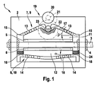
- disc brake 1 has a floating caliper as caliper 2, which is guided transversely to a brake disc 3 slidably. Sliding guides 4 are shown symbolically in the drawing. Instead of the caliper 2 and the brake disc 3 floating, ie be mounted axially displaceable. On each side of the brake disc 3, a friction brake lining 5, 6 is arranged in the brake caliper 2.
- the disc brake 1 has, for each friction brake lining 5, 6, a mechanical self-reinforcing device 7, 8 with a wedge mechanism 9, 10.
- Each of the two friction brake linings 5, 6 has on a rear side facing away from the brake disc 3 a wedge body 11, 12 with wedge surfaces 13, 14, with which the wedge body 11, 12 are supported on complementary abutments 15, 16 of the caliper 2.
- the abutments 15, 16 extend at the same angle obliquely to the brake disc 3 as the associated wedge surfaces 13, 14 of the wedge body 11, 12. This angle is referred to as a wedge angle ⁇ , ⁇ .
- the wedge surfaces 13, 14 and the abutments 15, 16 extend in the wedge angle ⁇ , ⁇ obliquely and in the circumferential direction of the brake disc 3, they preferably form the brake disc 3 equiaxial screw paths with the wedge angles ⁇ , ⁇ corresponding slope. It is also possible a different direction of the wedge surfaces 13, 14 and the abutments 15, 16, for example in a chord direction and in the wedge angles ⁇ , ⁇ to the brake disc 3.
- the friction brake pads 5, 6 are with their wedge bodies 11, 12 along the abutment 15, 16, ie in the circumferential direction to the brake disc 3 and in the wedge angles ⁇ , ⁇ obliquely to the brake disc 3 slidably.
- both wedge body 11, 12 opposite obliquely to the brake disc 3 extending wedge surfaces 13, 14 and the caliper 2 corresponding abutment 15, 16 for both directions of rotation of the brake disc 3.
- the wedge angle ⁇ , ⁇ may be the same or different sizes for the two directions of rotation of the brake disc 3, the latter to different levels of self-reinforcements for the two directions of rotation To reach brake disc 3.
- the wedge body 11, 12 with rollers as rolling elements 17, 18 roller bearings.
- the rolling elements 17, 18 are arranged between the wedge surfaces 13, 14 and the abutments 15, 16.
- the disc brake 1 has an electromechanical actuating device 19 with an electric motor 20 and a gear reduction gear 21. Gears of the gear transmission 21 are located above a plane and are therefore shown with two-dot chain lines. Via the gear transmission 21, the electric motor 20 drives a rotatably mounted on the brake caliper 2 gear 22, which meshes with a rack 23 of the two wedge body 11.
- the rack 23 extends in the direction of the friction brake pad 5, ie parallel to the wedge surfaces 13 and the abutments 15. Because of the opposite slopes of the wedge surfaces 13 and the abutment 15, the rack 23 is angled or curved in its center.
- the electric motor 20 is always energized so that the friction brake lining 5 shifts in the direction of rotation of the brake disc 3.
- the friction brake lining 5 shifts obliquely along the abutment 15 toward the brake disk 3 until it bears against the brake disk 3.
- the friction brake lining 5, whose wedge body 11 is displaced with the electromechanical actuating device 19, is also referred to below as the actuated friction brake lining 5.
- the other friction brake lining 6, which is arranged on the opposite side of the brake disk 3, will hereinafter also be referred to as non-actuated friction brake lining 6.
- the brake caliper 2 Upon further displacement of the actuated friction brake lining 5, the brake caliper 2 is displaced transversely to the brake disk 3 until the non-actuated friction brake lining 6 also bears against the brake disk 3.
- the rotating brake disc 3 acts on the two Reibbremsbeläge 5, 6 in narrowing wedge gaps between the abutments 15, 16 and the brake disc 3. Due to the support at the obliquely below the wedge angles ⁇ , ⁇ to the brake disc 3 extending abutments 15, 16 support the abutment 15, 16, the friction brake pads 5, 6 with a supporting force, which has a component perpendicular to the brake disc 3 and the friction brake linings 5, 6 in addition to the actuator 19 presses against the brake disc 3.
- the disc brake 1 has a self-boosting.
- FIG. 1 is the self-energizing device 8 of the non-actuated friction brake lining 6 wegverMarchnd formed. It has return springs 24 which support the wedge body 12 on the brake caliper 2 against displacement in the direction of rotation of the brake disk 3.
- the non-actuated friction brake lining 6 shifts so far in the direction of rotation of the brake disk 3 until the friction force exerted by the rotating brake disk 3 on the friction brake lining 6 and the oppositely directed spring force of the return spring 24 maintain equilibrium.
- the wedge angle ⁇ can therefore be selected to be acute, in such a way that the tangent of the wedge angle ⁇ is smaller than a coefficient of friction ⁇ between the friction brake lining 6 and the brake disc 3.
- the self-energizing device 7 of the actuated friction brake lining 5 is force-enhancing, the tangent of the wedge angle ⁇ is greater than the coefficient of friction ⁇ between the friction brake lining 5 and the brake disk 3, so that the self-energizing device 7 of the actuated friction brake lining 5 is not self-locking.
- a self-locking design of the self-reinforcing device 7 of the actuated friction brake lining 5 is also possible. In this case, the tangent of the wedge angle ⁇ is smaller than the coefficient of friction ⁇ .
- the actuated friction brake lining 5 must be self-locking design of the self-energizing device 7 are retained by the electromechanical actuator 19 against a co-movement with the rotating brake disc 3 in the Kell gap between the abutment 15 and the brake disc 3.
- a path-enhancing self-boosting device 7 as in the yet to be explained FIG. 2 is a retention of the actuated friction brake pad 5 in self-locking design of the self-energizing device 7 is not required.
- the power-boosting self-energizing device 7 of the actuated friction brake pad 5 with the wedge mechanism 9 has no return springs.
- the clamping force with which the friction brake lining 5 is pressed against the brake disk 3 is determined by the actuating force exerted by the actuating device 19 and the frictional force exerted by the rotating brake disk 3 on the friction brake lining 5 pressed against it, both via the support of the wedge body 11 of the friction brake pad 5 on the abutment 15 act.
- the clamping force with which both friction brake linings 5, 6 are pressed against the brake disk 3 is the same on both sides of the brake disk 3 and for both friction brake linings 5, 6.
- the path gain and the force amplification have a high self-amplification, but the control of the clamping force and the braking force is the same as with a disc brake with only one power-boosting self-boosting device.
- a self-locking does not occur if the force-enhancing self-reinforcing device 7 is not designed to be self-locking by selecting a correspondingly large wedge angle ⁇ .
- FIG. 2 In contrast to FIG. 1 is at the disc brake 1 off FIG. 2 Not only the self-reinforcing device 8 of the non-actuated friction brake lining 6, but also the self-energizing device 7 of the actuated friction brake pad 5 wegverMarchnd formed, it has return springs 25 which support the wedge body 11 of the actuated friction brake pad 5 in the direction of rotation of the brake disc 3 on the brake caliper 2.
- the wedge angle ⁇ of both self-energizing devices 7, 8 is in FIG. 2 chosen so acute that the tangent of the wedge angle ⁇ is smaller than the coefficient of friction ⁇ between the friction brake lining 5 and the brake disc 3.
- FIG. 1 has the actuator 19 of the disc brake 1 from FIG. 2 an electric motor 20 and a reduction gear 21 which rotationally drive a gear 22 mounted on the caliper 2.
- the abutment 15 of the self-reinforcing device 7 of the non-actuated friction brake lining 5 transversely to the brake disc 3 in the caliper 2 slidably.
- the gear 22 meshes with a rack 23 of the abutment 15, which extends transversely to the brake disc 3, so that by energizing the electric motor 20, the abutment 15 and on this the actuated friction brake lining 5 is moved transversely to the brake disc 3.
- the displacement of both friction brake linings 5, 6 along the abutments 15, 16 takes place by the frictional force of the rotating brake disk 3.
- both self-reinforcing devices 7, 8 are wegverParknd, shortened to be carried out by the actuator 19 actuating travel, but it does not increase the clamping force with which the friction brake linings 5, 6 are pressed against the brake disc 3.
- the clamping force corresponds to the force applied by the actuator 19 actuating force perpendicular to the brake disc 3.
- the control or regulation of the clamping or braking force in spite of the self-boosting as in a disc brake without self-boosting.
- a control or regulation of the clamping force is not difficult in spite of the high self-boost by the two self-energizing devices 7, 8 in comparison with a disc brake without self-boosting.
- FIG. 2 illustrated disc brake 1 is identical and works in the same way as the disc brake 1 from FIG. 1 , To avoid repetition will be explained by FIG. 2 in that regard, to the explanations given by FIG. 1 directed.
- the same components are provided in both figures with the same reference numerals.
Abstract
Description
- Die Erfindung betrifft eine Scheibenbremse mit mechanischer Selbstverstärkung mit den Merkmalen des Oberbegriffs des Anspruchs 1.
- Derartige Scheibenbremsen für Fahrzeuge, insbesondere Kraftfahrzeuge, sind bekannt. Beispielhaft wird auf die
WO 02/40 887 A1 - Die bekannte Scheibenbremse weist eine mechanische Selbstverstärkungseinrichtung mit einem Keilmechanismus auf. Der Reibbremsbelag ist in Umfangs-und Drehrichtung der Bremsscheibe bzw. in einem Winkel schräg zu ihr verschiebbar, er stützt sich mit einem Keil auf seiner der Bremsscheibe abgewandten Rückseite bzw. an einem schräg zur Bremsscheibe verlaufenden Widerlager im Bremssattel in einem Keilwinkel schräg zur Bremsscheibe ab. Wird der Reibbremsbelag zur Bremsbetätigung gegen die Bremsscheibe gedrückt, übt die drehende Bremsscheibe eine Reibungskraft in ihrer Drehrichtung auf den Reibbremsbelag aus. Die Reibungskraft beaufschlagt den Reibbremsbelag in einen enger werdenden Keilspalt zwischen dem Widerlager des Bremssattels und der Bremsscheibe. Nach dem sog. Keilprinzip bewirkt die Abstützung am Widerlager eine Abstützkraft senkrecht zum Widerlager. Die Abstützkraft weist eine Kraftkomponente senkrecht zur Bremsscheibe auf, die den Reibbremsbelag zusätzlich zu einer von der Betätigungseinrichtung ausgeübten Betätigungskraft gegen die Bremsscheibe drückt und dadurch eine Spannkraft, mit der der Reibbremsbelag insgesamt gegen die Bremsscheibe gedrückt wird, erhöht. Die Scheibenbremse weist somit eine Selbstverstärkung auf.
- Anstatt kraftverstärkend wie vorstehend anhand der
WO 02/40 887 A1 - Genügt die Selbstverstärkung bei einer Drehrichtung der Bremsscheibe, ist ein Keilmechanismus mit einer Keilschräge in einer Umfangsrichtung der Bremsscheibe ausreichend. Allgemein genügt zur Selbstverstärkung für eine Drehrichtung der Bremsscheibe eine Selbstverstärkungseinrichtung, die nur in dieser einen Drehrichtung wirksam ist. Damit die Selbstverstärkung für beide Drehrichtungen der Bremsscheibe wirksam ist, weist der Keilmechanismus der bekannten Scheibenbremse Keile bzw. Widerlager im Bremssattel auf, die entgegengesetzt schräg zur Bremsscheibe verlaufen. Der Reibbremsbelag verschiebt sich immer entlang der Keilschräge, die schräg in Drehrichtung auf die Bremsscheibe zu verläuft. Die Keilwinkel können für beide Drehrichtungen der Bremsscheibe gleich oder unterschiedlich sein, in letzterem Fall ist die Höhe der Selbstverstärkung verschieden.
- Es sind auch sog. Rampenmechanismen bekannt und für die Erfindung verwendbar im Unterschied zu einem Keilmechanismus mit einem über die gesamte Länge des Keils oder des Widerlagers konstantem Keilwinkel weist ein Rampenmechanismus einen sich im Verlauf einer Rampe ändernden Rampenwinkel, also eine sich ändernde Steigung auf. Durch einen zunächst steilen Rampenwinkel wird eine schnelle Zustellung des Reibbremsbelags zur Bremsscheibe erzielt, wodurch sich ein Lüftspiel, also ein Spalt zwischen der Bremsscheibe und dem Reibbremsbelag bei nicht betätigter Bremse, schnell überwinden lässt. Durch einen bei zunehmender Verschiebung des Reibbremsbelags mit zunehmender Spannkraft spitzer werdenden Rampenwinkel erhöht sich die Selbstverstärkung bei hoher Spannkraft. Auch ein Rampenmechanismus mit sich über den Verlauf einer Rampe änderndem Rampenwinkel soll als Keilmechanismus im Sinne der Erfindung verstanden werden.
- Die Patentschrift
DE 1 157 445 B offenbart eine Duo-Servo-Teilbelagscheibenbremse mit einem Schwimmsattel und mit einer hydraulischen Kolben-Zylinder-Einheit zur Bremsbetätigung. Im Schwimmsattel ist ein schwimmender Rahmen angeordnet, in welchem ein Reibbremsbelag auf einer Seite einer Bremsscheibe fest angeordnet ist und in welchem auf einer gegenüberliegenden Seite der Bremsscheibe ein zweiter Reibbremsbelag in Umfangsrichtung der Bremsscheibe beweglich angeordnet ist. Der schwimmende Rahmen stützt sich über Schrägfläche und Wälzkörper am Schwimmsattel ab, der bewegliche Reibbremsbelag stützt sich über Schrägflächen und Wälzkörper am schwimmenden Rahmen ab. Die Schrägflächen und die Wälzkörper bilden Selbstverstärkungseinrichtungen. Bei einer Bremsbetätigung verschiebt der Kolben im Schwimmsattel den schwimmenden Rahmen quer zur Bremsscheibe und drückt dadurch den festen Reibbremsbelag gegen die eine Seite der Bremsscheibe. Der Schwimmsattel bewegt sich entgegengesetzt zum schwimmenden Rahmen quer zu Bremsscheibe und drückt über einen Anschlag den anderen Reibbremsbelag gegen die andere Seite der Bremsscheibe. Die drehende Bremsscheibe verschiebt über den festen Reibbremsbelag den schwimmenden Rahmen in Drehrichtung, wodurch die eine Selbstverstärkungseinrichtung aktiviert wird, und die drehende Bremsscheibe verschiebt den beweglichen Reibbremsbelag in Drehrichtung, wodurch die andere, zwischen dem anderen Reibbremsbelag und dem schwimmenden Rahmen angeordnete Selbstverstärkungseinrichtung aktiviert wird. - Die Offenlegungsschrift
DE 103 07 224 A1 offenbart eine Scheibenbremse mit einer mechanischen Selbstverstärkungseinrichtung. Eine Bremsbetätigung erfolgt über ein Keilgetriebe, dessen Keil von einer Feder verschoben wird und dadurch einen Reibbremsbelag gegen eine Bremsscheibe drückt. Ein Lösen der Scheibenbremse erfolgt mit einem Aktuator, der den Keil des Keilgetriebes gegen die Kraft des Federelements in Löserichtung verschiebt. - Es sind auch andere mechanische Selbstverstärkungseinrichtungen bekannt und im Rahmen der Erfindung möglich. Beispielsweise ist eine Selbstverstärkung mit einem oder mehreren zueinander parallelen Stützhebeln möglich, die den Reibbremsbelag schräg unter einem Stützwinkel zur Bremsscheibe abstützen. Es handelt sich um ein mechanisches Analogon zu einem Keilmechanismus.
- Die erfindungsgemäße Scheibenbremse mit den Merkmalen des Anspruchs 1 weist für jeden Reibbremsbelag eine mechanische Selbstverstärkungseinrichtung, also zwei Selbstverstärkungseinrichtungen auf. Das schließt eventuelle weitere Reibbremsbeläge mit oder ohne Selbstverstärkungseinrichtungen nicht aus. Die Selbstverstärkung der erfindungsgemäßen Scheibenbremse ist durch die zweite Selbstverstärkungseinrichtung erhöht, die erforderliche Betätigungsenergie der Betätigungseinrichtung ist entsprechend verringert. Dadurch verringert sich die Leistungsaufnahme der Betätigungseinrichtung, bei einer elektrisch betätigten Betätigungseinrichtung wird ein elektrisches Bordnetz eines Kraftfahrzeugs entsprechend weniger belastet. Auch kann die Betätigungseinrichtung auf Grund der geringeren Energie- und Leistungsanforderung kleiner und leichter dimensioniert sein. Das ist ein besonderer Vorteil bei einer an einem Fahrzeugrad angeordneten Radbremse wegen des dort üblicherweise engen und begrenzten Bauraums und weil die Radbremse eine ungefederte Masse ist.
- Mindestens eine Selbstverstärkungseinrichtung ist wegverstärkend, sie weist Rückstellfedern auf, die den Reibbremsbelag gegen eine Verschiebung in Drehrichtung der Bremsscheibe abstützen. Bei betätigter Scheibenbremse bewegt die drehende Bremsscheibe den gegen sie gedrückten Reibbremsbelag so weit in Drehrichtung, bis eine von der drehenden Bremsscheibe auf den gegen sie gedrückten Reibbremsbelag ausgeübte Reibungskraft im Gleichgewicht mit einer entgegengerichteten Federkraft der Rückstellfeder ist. Die Verschiebung des Reibbremsbelags in Drehrichtung der Bremsscheibe bewirkt eine Zustellung des Reibbremsbelags quer zur Bremsscheibe, welche einen Betätigungsweg verkürzt, den die Betätigungseinrichtung zur Bremsbetätigung ausführen muss.
- Die Betätigung kann an sich beliebig, also beispielsweise hydraulisch, pneumatisch, mechanisch, elektromechanisch, elektromagnetisch oder mit einem Piezoelement erfolgen. Auf Grund der hohen Selbstverstärkung und des bei wegverstärkender Selbstverstärkungseinrichtung kurzen Betätigungswegs eignet sich die erfindungsgemäße Scheibenbremse auch für beispielsweise eine elektromagnetische Betätigung oder eine Betätigung mit einem Piezoelement, deren Einsatz in bekannten selbstverstärkenden Scheibenbremsen zumindest problematisch ist.
- Die Unteransprüche haben vorteilhafte Ausgestaltungen und Weiterbildungen der im Anspruch 1 angegebenen Erfindung zum Gegenstand.
- Die Erfindung wird nachfolgend anhand in der Zeichnung dargestellter Ausführungsformen näher erläutert. Es zeigen:
- Figur 1
- eine erste Ausführungsform einer erfindungsgemäßen Scheibenbremse mit Blickrichtung radial von außen auf eine Bremsscheibe; und
- Figur 2
- eine zweite Ausführungsform der Erfindung, ebenfalls mit Blickrichtung radial von außen auf eine Bremsscheibe.
- Die Zeichnungen sind als schematisierte und teilweise vereinfachte Darstellungen zur Erläuterung und zum Verständnis der Erfindung zu verstehen.
- Die in
Figur 1 dargestellte erfindungsgemäße Scheibenbremse 1 weist einen Schwimmsattel als Bremssattel 2 auf, der quer zu einer Bremsscheibe 3 verschiebbar geführt ist. Schiebeführungen 4 sind in der Zeichnung symbolisch dargestellt. Anstelle des Bremssattels 2 kann auch die Bremsscheibe 3 schwimmend, d. h. axial verschieblich gelagert sein. Auf jeder Seite der Bremsscheibe 3 ist ein Reibbremsbelag 5, 6 im Bremssattel 2 angeordnet. - Die Scheibenbremse 1 weist für jeden Reibbremsbelag 5, 6 eine mechanische Selbstverstärkungseinrichtung 7, 8 mit einem Keilmechanismus 9, 10 auf. Jeder der beiden Reibbremsbeläge 5, 6 weist auf einer der Bremsscheibe 3 abgewandten Rückseite einen Keilkörper 11, 12 mit Keilflächen 13, 14 auf, mit denen sich die Keilkörper 11, 12 an komplementären Widerlagern 15, 16 des Bremssattels 2 abstützen. Die Widerlager 15, 16 verlaufen im gleichen Winkel schräg zur Bremsscheibe 3 wie die zugeordneten Keilflächen 13, 14 der Keilkörper 11, 12. Dieser Winkel wird als Keilwinkel α, β bezeichnet. Die Keilflächen 13, 14 und die Widerlager 15, 16 verlaufen im Keilwinkel α, β schräg und in Umfangsrichtung zur Bremsscheibe 3, sie bilden vorzugsweise zur Bremsscheibe 3 gleichachsige Schraubenbahnen mit einer den Keilwinkeln α, β entsprechenden Steigung. Möglich ist auch eine abweichende Richtung der Keilflächen 13, 14 und der Widerlager 15, 16, beispielsweise in einer Sehnenrichtung und in den Keilwinkeln α, β zur Bremsscheibe 3. Die Reibbremsbeläge 5, 6 sind mit ihren Keilkörpern 11, 12 entlang der Widerlager 15, 16, also in Umfangsrichtung zur Bremsscheibe 3 und in den Keilwinkeln α, β schräg zur Bremsscheibe 3 verschiebbar.
- Bei der dargestellten Ausführungsform der Erfindung weisen beide Keilkörper 11, 12 entgegengesetzt schräg zur Bremsscheibe 3 verlaufende Keilflächen 13, 14 und der Bremssattels 2 entsprechende Widerlager 15, 16 für beide Drehrichtungen der Bremsscheibe 3 auf. Die Keilwinkel α, β können für die beiden Drehrichtungen der Bremsscheibe 3 gleich oder verschieden groß sein, letzteres um unterschiedlich hohe Selbstverstärkungen für die beiden Drehrichtungen der Bremsscheibe 3 zu erreichen. Zur Reibungsminderung sind die Keilkörper 11, 12 mit Rollen als Wälzkörper 17, 18 wälzgelagert. Die Wälzkörper 17, 18 sind zwischen den Keilflächen 13, 14 und den Widerlagern 15, 16 angeordnet.
- Zur Bremsbetätigung weist die Scheibenbremse 1 eine elektromechanische Betätigungseinrichtung 19 mit einem Elektromotor 20 und einem Zahnrad-Untersetzungsgetriebe 21 auf. Zahnräder des Zahnradgetriebes 21 befinden sich oberhalb einer Zeichenebene und sind deswegen mit Strich-2-Punkt-Linien dargestellt. Über das Zahnradgetriebe 21 treibt der Elektromotor 20 ein drehbar am Bremssattel 2 gelagertes Zahnrad 22 an, das mit einer Zahnstange 23 eines der beiden Keilkörper 11 kämmt. Die Zahnstange 23 verläuft in der Verschieberichtung des Reibbremsbelags 5, also parallel zu den Keilflächen 13 und den Widerlagern 15. Wegen der entgegengesetzten Steigungen der Keilflächen 13 und der Widerlager 15 ist die Zahnstange 23 in ihrer Mitte abgewinkelt oder gekrümmt.
- Zur Betätigung der Scheibenbremse 1 wird der Elektromotor 20 stets so bestromt, dass sich der Reibbremsbelag 5 in Drehrichtung der Bremsscheibe 3 verschiebt. Der Reibbremsbelag 5 verschiebt sich entlang des Widerlagers 15 schräg auf die Bremsscheibe 3 zu, bis er an der Bremsscheibe 3 anliegt. Der Reibbremsbelag 5, dessen Keilkörper 11 mit der elektromechanischen Betätigungseinrichtung 19 verschoben wird, wird nachfolgend auch als aktuierter Reibbremsbelag 5 bezeichnet. Der andere Reibbremsbelag 6, der auf der gegenüber liegenden Seite der Bremsscheibe 3 angeordnet ist, wird nachfolgend auch als nicht-aktuierter Reibbremsbelag 6 bezeichnet werden. Beim weiteren Verschieben des aktuierten Reibbremsbelags 5 wird der Bremssattel 2 quer zur Bremsscheibe 3 verschoben, bis auch der nicht-aktuierte Reibbremsbelag 6 an der Bremsscheibe 3 anliegt. Die drehende Bremsscheibe 3 beaufschlagt die beiden Reibbremsbeläge 5, 6 in enger werdende Keilspalte zwischen den Widerlagern 15, 16 und der Bremsscheibe 3. Auf Grund der Abstützung an den schräg unter den Keilwinkeln α, β zur Bremsscheibe 3 verlaufenden Widerlagern 15, 16 stützen die Widerlager 15, 16 die Reibbremsbeläge 5, 6 mit einer Abstützkraft ab, die eine Komponente senkrecht zur Bremsscheibe 3 aufweist und die Reibbremsbeläge 5, 6 zusätzlich zur Betätigungseinrichtung 19 gegen die Bremsscheibe 3 drückt. Die Scheibenbremse 1 weist eine Selbstverstärkung auf.
- In
Figur 1 ist die Selbstverstärkungseinrichtung 8 des nicht-aktuierten Reibbremsbelags 6 wegverstärkend ausgebildet. Sie weist Rückstellfedern 24 auf, die den Keilkörper 12 am Bremssattel 2 gegen eine Verschiebung in Drehrichtung der Bremsscheibe 3 abstützen. Der nicht-aktuierte Reibbremsbelag 6 verschiebt sich so weit in Drehrichtung der Bremsscheibe 3, bis sich die von der drehenden Bremsscheibe 3 auf den Reibbremsbelag 6 ausgeübte Reibungskraft und die entgegen gerichtete Federkraft der Rückstellfeder 24 das Gleichgewicht halten. Die wegverstärkende Selbstverstärkungseinrichtung 8 des nicht-aktuierten Reibbremsbelags 6 mit dem Keilmechanismus 10 bewirkt durch die Verschiebung des Reibbremsbelags 6 entlang des schräg zur Bremsscheibe 3 verlaufenden Widerlagers 16 den Weg des Reibbremsbelags 6 quer zur Bremsscheibe 3, der eine elastische Aufweitung des Bremssattels 2 und eine Elastizität der Reibbremsbeläge 5, 6 ausgleicht. Dem entsprechend verkürzt sich ein Betätigungsweg, den die elektromechanische Betätigungseinrichtung 19 zur Bremsbetätigung und zum Erreichen einer bestimmten Bremskraft ausführen muss. Auf Grund der den Verschiebeweg des Reibbremsbelags 6 begrenzenden Rückstellfeder 24 tritt auch bei einem spitzen Keilwinkel α keine Selbsthemmung auf. Der Keilwinkel α kann deswegen spitz gewählt werden, und zwar so, dass der Tangens des Keilwinkels α kleiner als ein Reibwert µ zwischen dem Reibbremsbelag 6 und der Bremsscheibe 3 ist. - Die Selbstverstärkungseinrichtung 7 des aktuierten Reibbremsbelags 5 ist kraftverstärkend, der Tangens des Keilwinkels β ist größer als der Reibwert µ zwischen dem Reibbremsbelag 5 und der Bremsscheibe 3, so dass die Selbstverstärkungseinrichtung 7 des aktuierten Reibbremsbelags 5 nicht selbsthemmend ist. Allerdings ist auch eine selbsthemmende Auslegung der Selbstverstärkungseinrichtung 7 des aktuierten Reibbremsbelags 5 möglich. In diesem Fall ist der Tangens des Keilwinkels β kleiner als der Reibwert µ. Der aktuierte Reibbremsbelag 5 muss bei selbsthemmender Auslegung der Selbstverstärkungseinrichtung 7 von der elektromechanischen Betätigungseinrichtung 19 gegen eine Mitbewegung mit der drehenden Bremsscheibe 3 in den Kellspalt zwischen dem Widerlager 15 und der Bremsscheibe 3 rückgehalten werden. Bei einer wegverstärkenden Selbstverstärkungseinrichtung 7 wie in der noch zu erläuternden
Figur 2 ist ein Rückhalten des aktuierten Reibbremsbelags 5 bei selbsthemmender Auslegung der Selbstverstärkungseinrichtung 7 nicht erforderlich. - Die kraftverstärkende Selbstverstärkungseinrichtung 7 des aktuierten Reibbremsbelags 5 mit dem Keilmechanismus 9 weist keine Rückstellfedern auf. Hier bestimmt sich die Spannkraft, mit der der Reibbremsbelag 5 gegen die Bremsscheibe 3 gedrückt wird, durch die von der Betätigungseinrichtung 19 ausgeübte Betätigungskraft und die von der drehenden Bremsscheibe 3 auf den gegen sie gedrückten Reibbremsbelag 5 ausgeübte Reibungskraft, die beide über die Abstützung des Keilkörpers 11 des Reibbremsbelags 5 am Widerlager 15 wirken. Die Spannkraft, mit der beide Reibbremsbeläge 5, 6 gegen die Bremsscheibe 3 gedrückt werden, ist auf beiden Seiten der Bremsscheibe 3 und für beide Reibbremsbeläge 5, 6 gleich groß. Sie bestimmt sich wie erläutert aus der Betätigungskraft der Betätigungseinrichtung 19 und der Selbstverstärkung der kraftverstärkenden Selbstverstärkungseinrichtung 7. Durch die Wegverstärkung und die Kraftverstärkung weist die Scheibenbremse 1 eine hohe Selbstverstärkung auf, trotzdem ist die Steuerung oder Regelung der Spannkraft und der Bremskraft gleich wie bei einer Scheibenbremse mit nur einer kraftverstärkenden Selbstverstärkungseinrichtung. Eine Selbsthemmung tritt dann nicht auf, wenn die kraftverstärkende Selbstverstärkungseinrichtung 7 nicht selbsthemmend ausgelegt ist durch Wahl eines entsprechend großen Keilwinkels β.
- Im Unterschied zu
Figur 1 ist bei der Scheibenbremse 1 ausFigur 2 nicht nur die Selbstverstärkungseinrichtung 8 des nicht-aktuierten Reibbremsbelags 6, sondern auch die Selbstverstärkungseinrichtung 7 des aktuierten Reibbremsbelags 5 wegverstärkend ausgebildet, sie weist Rückstellfedern 25 auf, die den Keilkörper 11 des aktuierten Reibbremsbelags 5 in Drehrichtung der Bremsscheibe 3 am Bremssattel 2 abstützen. Der Keilwinkel α beider Selbstverstärkungseinrichtungen 7, 8 ist inFigur 2 so spitz gewählt, dass der Tangens des Keilwinkels α kleiner als der Reibwert µ zwischen dem Reibbremsbelag 5 und der Bremsscheibe 3 ist. - Wie in
Figur 1 weist die Betätigungseinrichtung 19 der Scheibenbremse 1 ausFigur 2 einen Elektromotor 20 und ein Untersetzungsgetriebe 21 auf, die ein am Bremssattel 2 gelagertes Zahnrad 22 drehend antreiben. Im Unterschied zuFigur 1 ist inFigur 2 das Widerlager 15 der Selbstverstärkungseinrichtung 7 des nicht-aktuierten Reibbremsbelags 5 quer zur Bremsscheibe 3 im Bremssattel 2 verschiebbar. Das Zahnrad 22 kämmt mit einer Zahnstange 23 des Widerlagers 15, die quer zur Bremsscheibe 3 verläuft, so dass durch Bestromung des Elektromotors 20 das Widerlager 15 und über dieses der aktuierte Reibbremsbelag 5 quer zur Bremsscheibe 3 verschoben wird. Die Verschiebung beider Reibbremsbeläge 5, 6 entlang der Widerlager 15, 16 erfolgt durch die Reibungskraft der drehenden Bremsscheibe 3. - Weil beide Selbstverstärkungseinrichtungen 7, 8 wegverstärkend sind, verkürzt sich der von der Betätigungseinrichtung 19 auszuführende Betätigungsweg, es erhöht sich jedoch nicht die Spannkraft, mit der die Reibbremsbeläge 5, 6 gegen die Bremsscheibe 3 gedrückt werden. Die Spannkraft entspricht der von der Betätigungseinrichtung 19 aufgebrachten Betätigungskraft senkrecht zur Bremsscheibe 3. Im gesamten Reibwertstreubereich ist die Steuerung oder Regelung der Spann- oder Bremskraft trotz der Selbstverstärkung so wie bei einer Scheibenbremse ohne Selbstverstärkung. Eine Steuerung oder Regelung der Spannkraft ist trotz der hohen Selbstverstärkung durch die beiden Selbstverstärkungseinrichtungen 7, 8 nicht erschwert im Vergleich mit einer Scheibenbremse ohne Selbstverstärkung. Ein weiterer Vorteil der Scheibenbremse 1 aus
Figur 2 mit zwei wegverstärkenden Selbstverstärkungseinrichtungen 7, 8 ist die Vermeidung der Selbsthemmung auch bei spitzem Keilwinkel α. Ein weiterer Vorteil ist ein einfacher Verschleißausgleich, indem beim Lösen die Scheibenbremse 1 so weit geöffnet wird, dass sich unabhängig von der Abnutzung der Reibbremsbeläge 5, 6 ein gewünschtes Lüftspiel zwischen den Reibbremsbeläge 5, 6 und der Bremsscheibe 3 einstellt. Diese Verschleißnachstellung ist unabhängig von der Drehrichtung der Bremsscheibe 3, weil die Betätigungseinrichtung 19 senkrecht zur Bremsscheibe 3 und nicht parallel zur den Widerlagern 15 wirkt. Auch die Betätigung, also die Drehrichtung des Elektromotors 20 ist unabhängig von der Drehrichtung der Bremsscheibe 3. - Im Übrigen ist die in
Figur 2 dargestellte Scheibenbremse 1 gleich ausgebildet und funktioniert in gleicher Weise wie die Scheibenbremse 1 ausFigur 1 . Zur Vermeidung von Wiederholungen wird zur Erläuterung vonFigur 2 insoweit auf die Erläuterungen derFigur 1 verwiesen. Gleiche Bauteile sind in beiden Figuren mit gleichen Bezugszahlen versehen.
Claims (6)
- Scheibenbremse mit mechanischer Selbstverstärkung, mit einem Bremssattel (2), in dem zwei Reibbremsbeläge (5, 6) angeordnet sind, von denen sich jeder auf einer Seite einer Bremsscheibe (3) befindet, mit einer Betätigungseinrichtung (Aktuator) (19), mit der einer der beiden Reibbremsbeläge (5) (aktuierter Reibbremsbelag) gegen die Bremsscheibe (3) drückbar ist, und mit einer mechanischen Selbstverstärkungseinrichtung (7) für einen der beiden Reibbremsbeläge (5), die eine bei betätigter Scheibenbremse (1) von der drehenden Bremsscheibe (3) auf den gegen sie gedrückten Reibbremsbelag (5) ausgeübte Reibungskraft in eine Hilfsenergie zur Bremsbetätigung wandelt, und mit einer zweiten mechanischen Selbstverstärkungseinrichtung (8) für den anderen Reibbremsbelag (6), dadurch gekennzeichnet, dass mindestens eine Selbstverstärkungseinrichtung (8) wegverstärkend ist und Rückstellfedern (24, 25) aufweist, die den Reibbremsbelag (5, 6) gegen eine Verschiebung in Drehrichtung der Bremsscheibe (3) abstützen.
- Scheibenbremse nach Anspruch 1, dadurch gekennzeichnet, dass mindestens eine der beiden Selbstverstärkungseinrichtungen (7, 8) einen Keilmechanismus (9, 10) aufweist.
- Scheibenbremse nach Anspruch 1, dadurch gekennzeichnet, dass mindestens eine der Selbstverstärkungseinrichtungen (7) kraftverstärkend ist
- Scheibenbremse nach Anspruch 1, dadurch gekennzeichnet, dass die Selbstverstärkungseinrichtung (8) des nicht-aktuierten Reibbremsbelags (6) wegverstärkend ist.
- Scheibenbremse nach Anspruch 2, dadurch gekennzeichnet, dass der Tangens des Keilwinkels α des Keilmechanismus (10) kleiner als der Reibwert zwischen dem Reibbremsbelag (6) und der Bremsscheibe (3) ist.
- Scheibenbremse nach Anspruch 1, dadurch gekennzeichnet, dass die Scheibenbremse (1) einen Schwimmsattel (2) aufweist und/oder die Bremsscheibe (3) schwimmend gelagert ist.
Applications Claiming Priority (2)
| Application Number | Priority Date | Filing Date | Title |
|---|---|---|---|
| DE200710054807 DE102007054807A1 (de) | 2007-11-16 | 2007-11-16 | Scheibenbremse mit mechanischer Selbstverstärkung |
| PCT/EP2008/065409 WO2009062970A1 (de) | 2007-11-16 | 2008-11-12 | Scheibenbremse mit mechanischer selbstverstärkung |
Publications (2)
| Publication Number | Publication Date |
|---|---|
| EP2222976A1 EP2222976A1 (de) | 2010-09-01 |
| EP2222976B1 true EP2222976B1 (de) | 2012-05-30 |
Family
ID=40297075
Family Applications (1)
| Application Number | Title | Priority Date | Filing Date |
|---|---|---|---|
| EP08849184A Not-in-force EP2222976B1 (de) | 2007-11-16 | 2008-11-12 | Scheibenbremse mit mechanischer selbstverstärkung |
Country Status (3)
| Country | Link |
|---|---|
| EP (1) | EP2222976B1 (de) |
| DE (1) | DE102007054807A1 (de) |
| WO (1) | WO2009062970A1 (de) |
Families Citing this family (2)
| Publication number | Priority date | Publication date | Assignee | Title |
|---|---|---|---|---|
| CN109356950A (zh) * | 2018-11-13 | 2019-02-19 | 金华职业技术学院 | 一种汽车电子楔式制动器 |
| CN113202887B (zh) * | 2021-05-21 | 2022-09-13 | 深圳市太美亚电子科技有限公司 | 一种新能源汽车制动装置 |
Family Cites Families (6)
| Publication number | Priority date | Publication date | Assignee | Title |
|---|---|---|---|---|
| DE1157445B (de) | 1963-11-14 | |||
| DE29901831U1 (de) * | 1999-02-03 | 1999-05-06 | Quenstedt Jan Dipl Ing | Backenbremse mit Servoeffekt |
| DE20007499U1 (de) * | 2000-04-26 | 2000-10-05 | Zimmer Guenther Stephan | Brems- und/oder Klemmvorrichtung für Führungen |
| DE10056451A1 (de) | 2000-11-14 | 2002-05-29 | Bosch Gmbh Robert | Scheibenbremse |
| DE10307224A1 (de) | 2003-02-20 | 2004-09-16 | Kendrion Binder Magnete Gmbh | Durch Fremdenergie betätigbare Bremsvorrichtung |
| DE102006001621A1 (de) * | 2006-01-11 | 2007-07-19 | Voith Turbo Gmbh & Co. Kg | Schaltbarer Freilauf und Leistungsübertragungseinheit mit schaltbarem Freilauf |
-
2007
- 2007-11-16 DE DE200710054807 patent/DE102007054807A1/de not_active Withdrawn
-
2008
- 2008-11-12 WO PCT/EP2008/065409 patent/WO2009062970A1/de active Application Filing
- 2008-11-12 EP EP08849184A patent/EP2222976B1/de not_active Not-in-force
Also Published As
| Publication number | Publication date |
|---|---|
| EP2222976A1 (de) | 2010-09-01 |
| DE102007054807A1 (de) | 2009-05-20 |
| WO2009062970A1 (de) | 2009-05-22 |
Similar Documents
| Publication | Publication Date | Title |
|---|---|---|
| EP1692413B1 (de) | Selbstverstärkende elektromechanische fahrzeugbremse | |
| EP1977133B1 (de) | Elektromechanische reibungsbremse | |
| EP1499813A1 (de) | Kraftfahrzeugbremsanlage mit parkbremsfunktion und elektromechanische radbremse für eine solche kraftfahrzeugbremsanlage | |
| EP1337764B1 (de) | Scheibenbremse mit selbstverstärkender wirkung | |
| DE10164317C1 (de) | Selbstverstärkende elektromechanische Teilbelagscheibenbremse mit verbesserter Reibebelagführung | |
| DE202007019089U1 (de) | Scheibenbremse mit Führungsplatte | |
| EP1761714B1 (de) | Selbstverstärkende elektromechanische reibungsbremse | |
| EP2076686B1 (de) | Selbstverstärkende scheibenbremse | |
| EP2655917B1 (de) | Reibungsbremse | |
| DE10218825A1 (de) | Kraftfahrzeugbremsanlage mit Parkbremsfunktion und elektromechanische Bremse für eine solche Kraftfahrzeugbremsanlage | |
| DE10328243B4 (de) | Scheibenbremse mit Selbstverstärkung | |
| DE102006045169A1 (de) | Selbstverstärkende Reibungsbremse | |
| EP2215376B1 (de) | Selbstverstärkende scheibenbremse | |
| WO2002010609A1 (de) | Scheibenbremse | |
| EP1655506A2 (de) | Scheibenbremse | |
| EP1778997B1 (de) | Elektromechanisch oder pneumatisch betätigbare scheibenbremse, insbesondere für ein nutzfahrzeug | |
| EP2222976B1 (de) | Scheibenbremse mit mechanischer selbstverstärkung | |
| DE10328242A1 (de) | Fahrzeugbremse mit Selbstverstärkung | |
| DE102007061093B4 (de) | Selbstverstärkende Scheibenbremse | |
| DE102005055442B3 (de) | Elektromechanische Bremse mit Notöffnungseinrichtung | |
| DE102006049534A1 (de) | Scheibenbremse | |
| DE102006045168A1 (de) | Selbstverstärkende Fahrzeugbremse |
Legal Events
| Date | Code | Title | Description |
|---|---|---|---|
| PUAI | Public reference made under article 153(3) epc to a published international application that has entered the european phase |
Free format text: ORIGINAL CODE: 0009012 |
|
| 17P | Request for examination filed |
Effective date: 20100616 |
|
| AK | Designated contracting states |
Kind code of ref document: A1 Designated state(s): AT BE BG CH CY CZ DE DK EE ES FI FR GB GR HR HU IE IS IT LI LT LU LV MC MT NL NO PL PT RO SE SI SK TR |
|
| AX | Request for extension of the european patent |
Extension state: AL BA MK RS |
|
| 17Q | First examination report despatched |
Effective date: 20101007 |
|
| DAX | Request for extension of the european patent (deleted) | ||
| GRAP | Despatch of communication of intention to grant a patent |
Free format text: ORIGINAL CODE: EPIDOSNIGR1 |
|
| GRAS | Grant fee paid |
Free format text: ORIGINAL CODE: EPIDOSNIGR3 |
|
| GRAA | (expected) grant |
Free format text: ORIGINAL CODE: 0009210 |
|
| AK | Designated contracting states |
Kind code of ref document: B1 Designated state(s): AT BE BG CH CY CZ DE DK EE ES FI FR GB GR HR HU IE IS IT LI LT LU LV MC MT NL NO PL PT RO SE SI SK TR |
|
| REG | Reference to a national code |
Ref country code: GB Ref legal event code: FG4D Free format text: NOT ENGLISH |
|
| REG | Reference to a national code |
Ref country code: CH Ref legal event code: EP |
|
| REG | Reference to a national code |
Ref country code: AT Ref legal event code: REF Ref document number: 560211 Country of ref document: AT Kind code of ref document: T Effective date: 20120615 |
|
| REG | Reference to a national code |
Ref country code: IE Ref legal event code: FG4D Free format text: LANGUAGE OF EP DOCUMENT: GERMAN |
|
| REG | Reference to a national code |
Ref country code: DE Ref legal event code: R096 Ref document number: 502008007347 Country of ref document: DE Effective date: 20120726 |
|
| REG | Reference to a national code |
Ref country code: NL Ref legal event code: VDEP Effective date: 20120530 |
|
| REG | Reference to a national code |
Ref country code: LT Ref legal event code: MG4D Effective date: 20120530 |
|
| PG25 | Lapsed in a contracting state [announced via postgrant information from national office to epo] |
Ref country code: LT Free format text: LAPSE BECAUSE OF FAILURE TO SUBMIT A TRANSLATION OF THE DESCRIPTION OR TO PAY THE FEE WITHIN THE PRESCRIBED TIME-LIMIT Effective date: 20120530 Ref country code: IS Free format text: LAPSE BECAUSE OF FAILURE TO SUBMIT A TRANSLATION OF THE DESCRIPTION OR TO PAY THE FEE WITHIN THE PRESCRIBED TIME-LIMIT Effective date: 20120930 Ref country code: NO Free format text: LAPSE BECAUSE OF FAILURE TO SUBMIT A TRANSLATION OF THE DESCRIPTION OR TO PAY THE FEE WITHIN THE PRESCRIBED TIME-LIMIT Effective date: 20120830 Ref country code: SE Free format text: LAPSE BECAUSE OF FAILURE TO SUBMIT A TRANSLATION OF THE DESCRIPTION OR TO PAY THE FEE WITHIN THE PRESCRIBED TIME-LIMIT Effective date: 20120530 Ref country code: CY Free format text: LAPSE BECAUSE OF FAILURE TO SUBMIT A TRANSLATION OF THE DESCRIPTION OR TO PAY THE FEE WITHIN THE PRESCRIBED TIME-LIMIT Effective date: 20120530 Ref country code: FI Free format text: LAPSE BECAUSE OF FAILURE TO SUBMIT A TRANSLATION OF THE DESCRIPTION OR TO PAY THE FEE WITHIN THE PRESCRIBED TIME-LIMIT Effective date: 20120530 |
|
| PG25 | Lapsed in a contracting state [announced via postgrant information from national office to epo] |
Ref country code: HR Free format text: LAPSE BECAUSE OF FAILURE TO SUBMIT A TRANSLATION OF THE DESCRIPTION OR TO PAY THE FEE WITHIN THE PRESCRIBED TIME-LIMIT Effective date: 20120530 Ref country code: GR Free format text: LAPSE BECAUSE OF FAILURE TO SUBMIT A TRANSLATION OF THE DESCRIPTION OR TO PAY THE FEE WITHIN THE PRESCRIBED TIME-LIMIT Effective date: 20120831 Ref country code: SI Free format text: LAPSE BECAUSE OF FAILURE TO SUBMIT A TRANSLATION OF THE DESCRIPTION OR TO PAY THE FEE WITHIN THE PRESCRIBED TIME-LIMIT Effective date: 20120530 Ref country code: LV Free format text: LAPSE BECAUSE OF FAILURE TO SUBMIT A TRANSLATION OF THE DESCRIPTION OR TO PAY THE FEE WITHIN THE PRESCRIBED TIME-LIMIT Effective date: 20120530 |
|
| PG25 | Lapsed in a contracting state [announced via postgrant information from national office to epo] |
Ref country code: CZ Free format text: LAPSE BECAUSE OF FAILURE TO SUBMIT A TRANSLATION OF THE DESCRIPTION OR TO PAY THE FEE WITHIN THE PRESCRIBED TIME-LIMIT Effective date: 20120530 Ref country code: DK Free format text: LAPSE BECAUSE OF FAILURE TO SUBMIT A TRANSLATION OF THE DESCRIPTION OR TO PAY THE FEE WITHIN THE PRESCRIBED TIME-LIMIT Effective date: 20120530 Ref country code: RO Free format text: LAPSE BECAUSE OF FAILURE TO SUBMIT A TRANSLATION OF THE DESCRIPTION OR TO PAY THE FEE WITHIN THE PRESCRIBED TIME-LIMIT Effective date: 20120530 Ref country code: SK Free format text: LAPSE BECAUSE OF FAILURE TO SUBMIT A TRANSLATION OF THE DESCRIPTION OR TO PAY THE FEE WITHIN THE PRESCRIBED TIME-LIMIT Effective date: 20120530 Ref country code: NL Free format text: LAPSE BECAUSE OF FAILURE TO SUBMIT A TRANSLATION OF THE DESCRIPTION OR TO PAY THE FEE WITHIN THE PRESCRIBED TIME-LIMIT Effective date: 20120530 Ref country code: EE Free format text: LAPSE BECAUSE OF FAILURE TO SUBMIT A TRANSLATION OF THE DESCRIPTION OR TO PAY THE FEE WITHIN THE PRESCRIBED TIME-LIMIT Effective date: 20120530 |
|
| PG25 | Lapsed in a contracting state [announced via postgrant information from national office to epo] |
Ref country code: IT Free format text: LAPSE BECAUSE OF FAILURE TO SUBMIT A TRANSLATION OF THE DESCRIPTION OR TO PAY THE FEE WITHIN THE PRESCRIBED TIME-LIMIT Effective date: 20120530 Ref country code: PT Free format text: LAPSE BECAUSE OF FAILURE TO SUBMIT A TRANSLATION OF THE DESCRIPTION OR TO PAY THE FEE WITHIN THE PRESCRIBED TIME-LIMIT Effective date: 20121001 Ref country code: PL Free format text: LAPSE BECAUSE OF FAILURE TO SUBMIT A TRANSLATION OF THE DESCRIPTION OR TO PAY THE FEE WITHIN THE PRESCRIBED TIME-LIMIT Effective date: 20120530 |
|
| PLBE | No opposition filed within time limit |
Free format text: ORIGINAL CODE: 0009261 |
|
| STAA | Information on the status of an ep patent application or granted ep patent |
Free format text: STATUS: NO OPPOSITION FILED WITHIN TIME LIMIT |
|
| PG25 | Lapsed in a contracting state [announced via postgrant information from national office to epo] |
Ref country code: ES Free format text: LAPSE BECAUSE OF FAILURE TO SUBMIT A TRANSLATION OF THE DESCRIPTION OR TO PAY THE FEE WITHIN THE PRESCRIBED TIME-LIMIT Effective date: 20120910 |
|
| 26N | No opposition filed |
Effective date: 20130301 |
|
| BERE | Be: lapsed |
Owner name: ROBERT BOSCH G.M.B.H. Effective date: 20121130 |
|
| REG | Reference to a national code |
Ref country code: CH Ref legal event code: PL |
|
| REG | Reference to a national code |
Ref country code: DE Ref legal event code: R097 Ref document number: 502008007347 Country of ref document: DE Effective date: 20130301 |
|
| GBPC | Gb: european patent ceased through non-payment of renewal fee |
Effective date: 20121112 |
|
| PG25 | Lapsed in a contracting state [announced via postgrant information from national office to epo] |
Ref country code: LI Free format text: LAPSE BECAUSE OF NON-PAYMENT OF DUE FEES Effective date: 20121130 Ref country code: CH Free format text: LAPSE BECAUSE OF NON-PAYMENT OF DUE FEES Effective date: 20121130 Ref country code: BG Free format text: LAPSE BECAUSE OF FAILURE TO SUBMIT A TRANSLATION OF THE DESCRIPTION OR TO PAY THE FEE WITHIN THE PRESCRIBED TIME-LIMIT Effective date: 20120830 |
|
| REG | Reference to a national code |
Ref country code: IE Ref legal event code: MM4A |
|
| PG25 | Lapsed in a contracting state [announced via postgrant information from national office to epo] |
Ref country code: BE Free format text: LAPSE BECAUSE OF NON-PAYMENT OF DUE FEES Effective date: 20121130 |
|
| PG25 | Lapsed in a contracting state [announced via postgrant information from national office to epo] |
Ref country code: IE Free format text: LAPSE BECAUSE OF NON-PAYMENT OF DUE FEES Effective date: 20121112 |
|
| PG25 | Lapsed in a contracting state [announced via postgrant information from national office to epo] |
Ref country code: GB Free format text: LAPSE BECAUSE OF NON-PAYMENT OF DUE FEES Effective date: 20121112 Ref country code: MT Free format text: LAPSE BECAUSE OF FAILURE TO SUBMIT A TRANSLATION OF THE DESCRIPTION OR TO PAY THE FEE WITHIN THE PRESCRIBED TIME-LIMIT Effective date: 20120530 |
|
| PGFP | Annual fee paid to national office [announced via postgrant information from national office to epo] |
Ref country code: FR Payment date: 20131119 Year of fee payment: 6 |
|
| PG25 | Lapsed in a contracting state [announced via postgrant information from national office to epo] |
Ref country code: MC Free format text: LAPSE BECAUSE OF NON-PAYMENT OF DUE FEES Effective date: 20121130 Ref country code: TR Free format text: LAPSE BECAUSE OF FAILURE TO SUBMIT A TRANSLATION OF THE DESCRIPTION OR TO PAY THE FEE WITHIN THE PRESCRIBED TIME-LIMIT Effective date: 20120530 |
|
| PGFP | Annual fee paid to national office [announced via postgrant information from national office to epo] |
Ref country code: DE Payment date: 20140124 Year of fee payment: 6 |
|
| PG25 | Lapsed in a contracting state [announced via postgrant information from national office to epo] |
Ref country code: LU Free format text: LAPSE BECAUSE OF NON-PAYMENT OF DUE FEES Effective date: 20121112 |
|
| PG25 | Lapsed in a contracting state [announced via postgrant information from national office to epo] |
Ref country code: HU Free format text: LAPSE BECAUSE OF FAILURE TO SUBMIT A TRANSLATION OF THE DESCRIPTION OR TO PAY THE FEE WITHIN THE PRESCRIBED TIME-LIMIT Effective date: 20081112 |
|
| REG | Reference to a national code |
Ref country code: AT Ref legal event code: MM01 Ref document number: 560211 Country of ref document: AT Kind code of ref document: T Effective date: 20131112 |
|
| PG25 | Lapsed in a contracting state [announced via postgrant information from national office to epo] |
Ref country code: AT Free format text: LAPSE BECAUSE OF NON-PAYMENT OF DUE FEES Effective date: 20131112 |
|
| REG | Reference to a national code |
Ref country code: DE Ref legal event code: R119 Ref document number: 502008007347 Country of ref document: DE |
|
| REG | Reference to a national code |
Ref country code: FR Ref legal event code: ST Effective date: 20150731 |
|
| PG25 | Lapsed in a contracting state [announced via postgrant information from national office to epo] |
Ref country code: DE Free format text: LAPSE BECAUSE OF NON-PAYMENT OF DUE FEES Effective date: 20150602 |
|
| PG25 | Lapsed in a contracting state [announced via postgrant information from national office to epo] |
Ref country code: FR Free format text: LAPSE BECAUSE OF NON-PAYMENT OF DUE FEES Effective date: 20141201 |