EP2221000B1 - Punktionsvorrichtung - Google Patents
Punktionsvorrichtung Download PDFInfo
- Publication number
- EP2221000B1 EP2221000B1 EP08853790A EP08853790A EP2221000B1 EP 2221000 B1 EP2221000 B1 EP 2221000B1 EP 08853790 A EP08853790 A EP 08853790A EP 08853790 A EP08853790 A EP 08853790A EP 2221000 B1 EP2221000 B1 EP 2221000B1
- Authority
- EP
- European Patent Office
- Prior art keywords
- lancet
- piercing
- puncture
- puncture device
- housing
- Prior art date
- Legal status (The legal status is an assumption and is not a legal conclusion. Google has not performed a legal analysis and makes no representation as to the accuracy of the status listed.)
- Active
Links
- 230000007246 mechanism Effects 0.000 claims description 36
- 238000005452 bending Methods 0.000 claims description 15
- 238000006073 displacement reaction Methods 0.000 claims description 14
- 230000000717 retained effect Effects 0.000 claims description 12
- 230000001105 regulatory effect Effects 0.000 claims description 6
- 238000010304 firing Methods 0.000 description 4
- 238000003780 insertion Methods 0.000 description 4
- 230000037431 insertion Effects 0.000 description 4
- 239000008280 blood Substances 0.000 description 3
- 210000004369 blood Anatomy 0.000 description 3
- 210000000078 claw Anatomy 0.000 description 3
- 230000009467 reduction Effects 0.000 description 3
- 239000011435 rock Substances 0.000 description 3
- 230000009471 action Effects 0.000 description 1
- 239000012491 analyte Substances 0.000 description 1
- 210000001124 body fluid Anatomy 0.000 description 1
- 239000010839 body fluid Substances 0.000 description 1
- 230000008859 change Effects 0.000 description 1
- 230000006872 improvement Effects 0.000 description 1
- 238000000034 method Methods 0.000 description 1
- 238000012544 monitoring process Methods 0.000 description 1
- 238000000465 moulding Methods 0.000 description 1
- 230000008569 process Effects 0.000 description 1
- 239000011347 resin Substances 0.000 description 1
- 229920005989 resin Polymers 0.000 description 1
- 230000001954 sterilising effect Effects 0.000 description 1
Images


Classifications
-
- A—HUMAN NECESSITIES
- A61—MEDICAL OR VETERINARY SCIENCE; HYGIENE
- A61B—DIAGNOSIS; SURGERY; IDENTIFICATION
- A61B5/00—Measuring for diagnostic purposes; Identification of persons
- A61B5/15—Devices for taking samples of blood
- A61B5/150007—Details
- A61B5/150374—Details of piercing elements or protective means for preventing accidental injuries by such piercing elements
- A61B5/150534—Design of protective means for piercing elements for preventing accidental needle sticks, e.g. shields, caps, protectors, axially extensible sleeves, pivotable protective sleeves
- A61B5/15058—Joining techniques used for protective means
- A61B5/15061—Joining techniques used for protective means by material engagement, e.g. welding, bonding
-
- A—HUMAN NECESSITIES
- A61—MEDICAL OR VETERINARY SCIENCE; HYGIENE
- A61B—DIAGNOSIS; SURGERY; IDENTIFICATION
- A61B5/00—Measuring for diagnostic purposes; Identification of persons
- A61B5/15—Devices for taking samples of blood
- A61B5/150007—Details
- A61B5/150015—Source of blood
- A61B5/150022—Source of blood for capillary blood or interstitial fluid
-
- A—HUMAN NECESSITIES
- A61—MEDICAL OR VETERINARY SCIENCE; HYGIENE
- A61B—DIAGNOSIS; SURGERY; IDENTIFICATION
- A61B5/00—Measuring for diagnostic purposes; Identification of persons
- A61B5/15—Devices for taking samples of blood
- A61B5/150007—Details
- A61B5/150175—Adjustment of penetration depth
- A61B5/150198—Depth adjustment mechanism at the proximal end of the carrier of the piercing element
-
- A—HUMAN NECESSITIES
- A61—MEDICAL OR VETERINARY SCIENCE; HYGIENE
- A61B—DIAGNOSIS; SURGERY; IDENTIFICATION
- A61B5/00—Measuring for diagnostic purposes; Identification of persons
- A61B5/15—Devices for taking samples of blood
- A61B5/150007—Details
- A61B5/150374—Details of piercing elements or protective means for preventing accidental injuries by such piercing elements
- A61B5/150381—Design of piercing elements
- A61B5/150412—Pointed piercing elements, e.g. needles, lancets for piercing the skin
-
- A—HUMAN NECESSITIES
- A61—MEDICAL OR VETERINARY SCIENCE; HYGIENE
- A61B—DIAGNOSIS; SURGERY; IDENTIFICATION
- A61B5/00—Measuring for diagnostic purposes; Identification of persons
- A61B5/15—Devices for taking samples of blood
- A61B5/150007—Details
- A61B5/150374—Details of piercing elements or protective means for preventing accidental injuries by such piercing elements
- A61B5/150381—Design of piercing elements
- A61B5/150503—Single-ended needles
- A61B5/150519—Details of construction of hub, i.e. element used to attach the single-ended needle to a piercing device or sampling device
-
- A—HUMAN NECESSITIES
- A61—MEDICAL OR VETERINARY SCIENCE; HYGIENE
- A61B—DIAGNOSIS; SURGERY; IDENTIFICATION
- A61B5/00—Measuring for diagnostic purposes; Identification of persons
- A61B5/15—Devices for taking samples of blood
- A61B5/150007—Details
- A61B5/150374—Details of piercing elements or protective means for preventing accidental injuries by such piercing elements
- A61B5/150534—Design of protective means for piercing elements for preventing accidental needle sticks, e.g. shields, caps, protectors, axially extensible sleeves, pivotable protective sleeves
- A61B5/150541—Breakable protectors, e.g. caps, shields or sleeves, i.e. protectors separated destructively, e.g. by breaking a connecting area
- A61B5/150549—Protectors removed by rotational movement, e.g. torsion or screwing
-
- A—HUMAN NECESSITIES
- A61—MEDICAL OR VETERINARY SCIENCE; HYGIENE
- A61B—DIAGNOSIS; SURGERY; IDENTIFICATION
- A61B5/00—Measuring for diagnostic purposes; Identification of persons
- A61B5/15—Devices for taking samples of blood
- A61B5/150007—Details
- A61B5/150374—Details of piercing elements or protective means for preventing accidental injuries by such piercing elements
- A61B5/150534—Design of protective means for piercing elements for preventing accidental needle sticks, e.g. shields, caps, protectors, axially extensible sleeves, pivotable protective sleeves
- A61B5/150694—Procedure for removing protection means at the time of piercing
- A61B5/150717—Procedure for removing protection means at the time of piercing manually removed
-
- A—HUMAN NECESSITIES
- A61—MEDICAL OR VETERINARY SCIENCE; HYGIENE
- A61B—DIAGNOSIS; SURGERY; IDENTIFICATION
- A61B5/00—Measuring for diagnostic purposes; Identification of persons
- A61B5/15—Devices for taking samples of blood
- A61B5/151—Devices specially adapted for taking samples of capillary blood, e.g. by lancets, needles or blades
- A61B5/15101—Details
- A61B5/15103—Piercing procedure
- A61B5/15107—Piercing being assisted by a triggering mechanism
- A61B5/15113—Manually triggered, i.e. the triggering requires a deliberate action by the user such as pressing a drive button
-
- A—HUMAN NECESSITIES
- A61—MEDICAL OR VETERINARY SCIENCE; HYGIENE
- A61B—DIAGNOSIS; SURGERY; IDENTIFICATION
- A61B5/00—Measuring for diagnostic purposes; Identification of persons
- A61B5/15—Devices for taking samples of blood
- A61B5/151—Devices specially adapted for taking samples of capillary blood, e.g. by lancets, needles or blades
- A61B5/15101—Details
- A61B5/15115—Driving means for propelling the piercing element to pierce the skin, e.g. comprising mechanisms based on shape memory alloys, magnetism, solenoids, piezoelectric effect, biased elements, resilient elements, vacuum or compressed fluids
- A61B5/15117—Driving means for propelling the piercing element to pierce the skin, e.g. comprising mechanisms based on shape memory alloys, magnetism, solenoids, piezoelectric effect, biased elements, resilient elements, vacuum or compressed fluids comprising biased elements, resilient elements or a spring, e.g. a helical spring, leaf spring, or elastic strap
-
- A—HUMAN NECESSITIES
- A61—MEDICAL OR VETERINARY SCIENCE; HYGIENE
- A61B—DIAGNOSIS; SURGERY; IDENTIFICATION
- A61B5/00—Measuring for diagnostic purposes; Identification of persons
- A61B5/15—Devices for taking samples of blood
- A61B5/151—Devices specially adapted for taking samples of capillary blood, e.g. by lancets, needles or blades
- A61B5/15101—Details
- A61B5/15126—Means for controlling the lancing movement, e.g. 2D- or 3D-shaped elements, tooth-shaped elements or sliding guides
- A61B5/15128—Means for controlling the lancing movement, e.g. 2D- or 3D-shaped elements, tooth-shaped elements or sliding guides comprising 2D- or 3D-shaped elements, e.g. cams, curved guide rails or threads
-
- A—HUMAN NECESSITIES
- A61—MEDICAL OR VETERINARY SCIENCE; HYGIENE
- A61B—DIAGNOSIS; SURGERY; IDENTIFICATION
- A61B5/00—Measuring for diagnostic purposes; Identification of persons
- A61B5/15—Devices for taking samples of blood
- A61B5/151—Devices specially adapted for taking samples of capillary blood, e.g. by lancets, needles or blades
- A61B5/15186—Devices loaded with a single lancet, i.e. a single lancet with or without a casing is loaded into a reusable drive device and then discarded after use; drive devices reloadable for multiple use
- A61B5/15188—Constructional features of reusable driving devices
- A61B5/1519—Constructional features of reusable driving devices comprising driving means, e.g. a spring, for propelling the piercing unit
Definitions
- the present invention relates to a puncture device used for piercing a skin with a puncture element like a lancet for extracting blood, other body fluids and tissues for an examination.
- a puncture device has a lancet which is moved together with a lancet holder by the elastic force of a spring to pierce a skin.
- a device which allows a user to adjust a piercing depth of a lancet relative to a skin has been proposed (see, for example, Patent Literature 1).
- Patent Literature 1 a device which allows a user to adjust a piercing depth of a lancet relative to a skin has been proposed ( see, for example, Patent Literature 1).
- Patent Literature 1 Patent Literature 1
- According to such puncture device there is a possibility that a skin is pierced plural times caused by expanding and contracting motion of the spring unless energy imparted to the lancet holder is appropriately absorbed.
- a general lancet is attached in a lancet holder, and used after a protecting cover is removed.
- a puncture needle is exposed when the lancet is attached or discarded, so that there is a possibility that a fingertip or the like is hurt by the puncture needle. Therefore, there has been proposed a lancet, so called a safety lancet, configured to be retained in a casing so as to be bound in the casing when a user discards the lancet (see, for example, Patent Literature 3).
- a puncture needle is surrounded by the casing when the lancet is attached, and the lancet is bound in the casing when discarded, resulting in reduction of the possibility that the puncture needle hurts the fingertip or the like when the lancet is attached or discarded.
- the puncture device employing a cam mechanism
- the puncture device employs both cam mechanism and safety lancet combined together
- the puncture device employing a cam mechanism as the operation of a component each configuring the cam mechanism is linked with each other, the moving distance of the lancet holder is regulated by the shape of a component or the like.
- the safety lancet it is necessary to regulate a positional relation between the casing and the lancet so that the lancet is appropriately bound in the casing when attached and discarded.
- the present invention relates to a puncture device for moving a puncture element in a piercing direction toward a target site and for piercing the target site with the puncture element.
- the puncture device of the present invention comprises the features of claim 1.
- the piercing depth adjusting mechanism may further include an operation member for adjusting a position of the displacement member.
- the piercing depth adjusting mechanism includes, for example, a protruding part provided at either one of the displacement member and the operation member, and a recess provided at the other member.
- the protruding part and the recess engage with each other, and have a relative position changeable.
- the operation member is, for example, for adjusting the position of the displacement member by a rotating operation. It is preferable that a moving amount of the displacement member relative to an operation amount of the operation member should be in a nonlinear relation.
- the link member includes, for example, a rotating shaft with a fixed position, a movable part which is rotatable around the rotating shaft, and which causes a second member to followingly move relative to a rotational motion of the link member, and a hole for allowing positional displacement of the engaging part in the piercing direction and in the evacuating direction.
- the inclination part is a bending part comprising a first inclination part and a second inclination part which are inclined to different directions and are continuously connected to each other.
- the recess comprises, for example, a straight line part extending in the piercing direction and in the evacuating direction and connecting both ends of the bending part to each other.
- the puncture device of the present invention may further comprise a housing for retaining the first member, the second member and the link member.
- the first member is, for example, engaged with the housing as the first member is moved relative to the housing in the evacuating direction, and is for moving the second member in the piercing direction by releasing latching.
- the engaging part may move through the straight line part when the first member is relative to the housing in the evacuating direction.
- the puncture element is retained in the second element when attached in the houing, and conversely, when the casing is detached from the housing, the puncture element is detached from the second member and is bound by the casing so as to prevent a leading end of the puncture element from protruding from the casing.
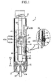
- a puncture device 1 shown in FIG. 1 is used for causing blood to flow out from a skin by moving a puncture needle 27B in a lancet device 2 in a piercing direction N1 to pierce the skin.
- the puncture device 1 comprises a housing 3, a lancet moving mechanism 4, a latch releasing member 5 and a piercing depth adjusting mechanism 6.
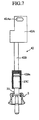
- the lancet device 2 attached in the puncture device 1 is a so-called safety lancet, and comprises a casing 20 and a lancet 21 as shown in FIG. 2A and FIG. 2B .
- the casing 20 is for retaining the lancet 21, and is formed in a tubular shape having openings 22 and 23.
- the casing 20 comprises a retaining part 24 for retaining a flange 27A of the lancet 21 to be discussed later.
- the retaining part 24 has a recess 25 for binding the flange 27A, and is expandable and openable in a radial direction of the casing 2 by a thin-walled part 26.
- the lancet 21 is used for piercing the skin, and is retained by a lancet holder 42 in the lancet moving mechanism 4 to be discussed later.
- the lancet 21 comprises a lancet main body 27, a cap 28 and a brittle part 29.
- the lancet main body 27 comprises an insertion end part 27C retained in a recess 42Ba of the lancet holder 42, and further comprises the flange 27A and the puncture needle 27B.
- the flange 27A is engaged with the retaining part 24 (the recess 25) of the casing 20, and is for preventing the lancet 21 (the lancet main body 27) from carelessly ejecting out from the casing 20.
- the puncture needle 27B is fixed in the lancet main body 27, and a needle tip thereof protrudes from the lancet main body 27.
- the cap 28 is for covering the needle tip of the puncture needle 27B, and is detachable from the lancet main body 27.
- the brittle part 29 is for facilitating removal of the cap 28 from the lancet main body 27.
- the above-explained lancet 21 can be formed as the puncture needle 27B is inserted therein by resin molding. Moreover, as a sterilizing process is performed on the lancet after the lancet is formed, the lancet 21 can maintain a clean condition until the cap 28 is detached and the needle tip of the puncture needle 27B is exposed.
- the housing 3 is for regulating a space for retaining various elements, and is formed in a cylindrical shape as a whole.
- the housing 3 comprises a housing main body 30 and a leading-end sleeve 31.
- the housing main body 30 comprises a protruding part 32 and openings 33 and 34.
- the protruding part 32 is for latching a hook 41C of a moving member 41 in the lancet moving mechanism 4 to be discussed later.
- the opening 33 is for guiding an operation part 41B of the moving member 41.
- the opening 34 is for guiding a push-down part 50 of the latch releasing member 5.
- the leading-end sleeve 31 is for retaining the casing 20 of the lancet device 2, and has a claw35.
- the claw 35 interferes the retaining part 24 in the casing 20 when the lancet device 2 is attached in the housing 3, thereby expanding and opening the retaining part 24.
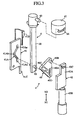
- the lancet moving mechanism 4 employs a cam mechanism, and comprises a link member 40, the moving member 41, and the lancet holder 42 as shown in FIG. 3 .
- the lancet moving mechanism 4 converts the translatory movement of the moving member 41 into the reciprocating motion of the lancet holder 42 through the rotational motion (rocking motion) of the link member 40.
- the link member 40 is for interlocking the lancet holder 42 with the movement of the moving member 41 when the moving member 41 moves and for moving the lancet holder 42.
- the link member 40 has a plate 40A, a movable shaft 40B and a fixed shaft 40C.
- the plate 40A is rotatable around the fixed shaft 40C, and is formed in a triangular shape. At respective corners of the plate 40A, the movable shaft 40B and the fixed shaft 40C are fixed while at the same time, a through-hole 40D is formed.
- the through-hole 40D is for engaging with an engaging pin 62 provided at a control arm 60 to be discussed later while allowing the engaging pin 62 to move.
- the movable shaft 40B is for moving the lancet holder 42 in the direction N1 and a direction N2 when the plate 40A rotates, and is engaged with a through-hole 42Aa of the lancet holder 42. Moreover, the movable shaft 40B is so fixed as not to be rotatable in an axial direction at the corner of the plate 40A, and a distance to the fixed shaft 40C is fixed.
- the fixed shaft 40C is for fixing the link member 40 rotatable relative to the housing 3.
- the fixed shaft 40C is so fixed as not to be rotatable in the axial direction at the corner of the plate 40A while at the same time being fixed rotatable in the axial direction relative to the housing 3.
- the moving member 41 is movable relative to the housing 3 in the directions N1 and N2, and is connected to the housing 3 through a coil spring 65.
- the moving member 41 comprises a groove 41A, the operation part 41 B and the hook 41 C.
- the groove 41A is for allowing the engaging pin 62 to be discussed later to move, and has a straight line part 41Aa and a bending part 41Ab.
- the straight line part 41Aa extends in the directions N1 and N2 while the bending part 41Ab is offset relative to the straight line part 4lAa as a whole. Accordingly, the link member 40 (the plate 40A) is rotated (rocked) when the engaging pin 62 moves through the bending part 41Ab.
- the operation part 41B is used when the moving member 41 is moved by hand.
- the operation part 41B has a portion thereof protruding toward the exterior through the opening 33 of the housing 3, while at the same time, is guided by the opening 33 to move in the directions N1 and N2.
- the hook 41C is for engaging with the protruding part 32 of the housing 32 (the housing main body 30), thereby latching the moving member 41 to the housing 3.
- the lancet holder 42 is for retaining the lancet 21 in the lancet device 2, and for moving the lancet 21.
- the lancet holder 42 comprises a plate 42A and a rod 42B.
- the plate 42A is moved as the movable shaft 40B of the link member 40 rotates (rocks), and has the through-hole 42Aa.
- the through-hole 42Aa is engaged with the movable shaft 40B, and is formed in a long hole extending in a direction perpendicular to the directions N1 and N2 so as to allow the plate 42A to move in the directions N1 and N2 when the movable shaft 40B is rotated (rocked).
- the rod 42B has the recess 42Ba for retaining the lancet 21.
- the recess 42Ba has an internal diameter substantially equal to an external diameter of the insertion end part 27C of the lancet 21 (the lancet main body 27).
- the latch releasing member 5 is for releasing latching of the moving member 41 from the housing 3 (the protruding part 32), and has the push-down part 50 and an elastic part 51.
- the push-down part 50 is exposed on the outer surface of the housing 3 and can wobble in a radial direction of the housing 3.
- the elastic part 51 has moderate elasticity, and extends from the push-down part 50, and is fixed to the housing 3 at an end part 52.
- the piercing depth adjusting mechanism 6 is for adjusting a protruding amount of the puncture needle 27B from the casing 20 of the lancet device 2 when a skin is pierced, i.e., an insertion depth of the puncture needle 27B relative to a skin Sk (see, FIG. 11B ).
- the piercing depth adjusting mechanism 6 comprises the control arm 60 and an operation cap 61.
- the control arm 60 has the engaging pin 62 and an engaging pin 63 respectively provided at both ends.
- the engaging pin 62 is for rocking (rotating) the plate 40A when moving through the bending part 41 Ab of the groove 41A, and engages with the through-hole 40D of the plate 40A of the link member 40 and the groove 41A of the moving member 41.
- the engaging pin 63 is for engaging with a groove 64 of the operation cap 61, and acts as a supporting point for wobbling the control arm 60 when the engaging pin 62 moves through the bending part 41Ab.
- the operation cap 61 is for adjusting positions of the control arm 60 in the directions N1 and N2, and is formed in a hollow cylindrical shape.
- the operation cap 61 is rotatable, and has the groove 64 for engaging with the engaging pin 63.
- the groove 64 is inclined to the direction perpendicular to the directions N1 and N2 (a horizontal direction in the figure), and is for displacing positions of the control arm 60 in the directions N1 and N2. That is, as shown in FIG. 9A to FIG. 9C , as the operation cap 61 is rotated, the engaging position with the engaging pin 63 changes, thereby displacing the control arm 60 in the directions N1 and N2.
- the shape of the groove 64 can be a shape such that the moving distance of the engaging pin 63 linearly changes relative to a rotation angle of the operation cap 61, or can be a shape such that the moving distance changes nonlinearly.
- the moving distance of the engaging pin 63 relative to the rotation angle of the operation cap 61 may be set to be smaller within the range of a general piercing depth. For example, within the smaller range of a piercing depth, the moving distance of the engaging pin 63 relative to the rotation angle of the operation cap 61 may be set to be smaller.
- the moving distance of the engaging pin 63 relative to the rotation angle of the operation cap 61 may be set to be larger. According to such configuration, when the range of a piercing depth is small, that is, when a small amount of blood is extracted, a piercing depth can be finely adjusted, which results in improvement of the usability of the puncture device.
- a distance D between the engaging pin 62 and the fixed shaft 40C of the link member 40 changes in accordance with a position of the engaging pin 62 in the groove 40D. Accordingly, by rotating the operation cap 61 and changing positions of the control arm 60 in the directions N1 and N2, it becomes possible to change the distance D between the engaging pin 62 and the fixed shaft 40C.
- the link member 40 is for converting the translatory movement of the moving member 41 into the reciprocating motion of the lancet holder 42. Accordingly, under a condition in which the stroke of the moving member 41 remains same, the distance D between the engaging pin 62 and the fixed shaft 40C of the link member 40 affects a rotation angle of the link member 40 when the engaging pin 62 moves through the groove 41A (see, FIG. 6A to FIG. 6C ). That is, the rotation angle of the link member 40 becomes large when the distance D is small, and in contrast, the rotation angle becomes small when the distance D is large.
- the lancet holder 42 is connected to the link member 40 through the movable shaft 40B, and a position of the lancet holder 42 is regulated by a position of the movable shaft 40B (see, FIG. 8A to FIG. 8C ). Accordingly, when the rotation angle of the link member 40 is large, positional displacement of the movable shaft 40B in the directions N 1 and N2 becomes large, thereby to increase a stroke L1 of the lancet holder 42. Consequently, the stroke of the lancet 21 retained by the lancet holder 42 becomes large and a maximum protruding amount L2 of the puncture needle 27B from the casing 20 and eventually, a piercing depth of the puncture needle 27B to the skin become large.
- the lancet 21 can be retained in the lancet holder 42 as the lancet device 2 is inserted from the opening 35 of the leading-end sleeve 31.
- the insertion end part 27C of the lancet 21 is fitted into the recess 42Ba of the lancet holder 42 as shown in FIG. 7 .
- the claw 35 of the leading-end sleeve 31 acts on the retaining part 24 of the casing 20 of the lancet device 2. Accordingly, the retaining part 24 expands in the radial direction, engagement of the retaining part 24 with the flange 27A of the lancet 21 is released, which leads the lancet 21 to be free relative to the casing 20.
- the hook 41C of the moving member 41 can be engaged with the protruding part 32 of the housing 3 as the operation part 41B of the moving member 41 is moved in the direction N2.
- the operation part 41B is moved by a predetermined distance in the direction N2
- the hook 41C is engaged with the protruding part 32 and the coil spring 65 is stretched.
- the cap 28 of the lancet 2 is detached.
- the cap 28 can be detached by twisting and moving the cap 28 in the direction N1.
- the puncture needle 27B As the puncture needle 27B is exposed from the lancet 21, when the lancet 21 is moved in the direction N1, the puncture needle 27B protrudes from the casing 20, and pierces the skin Sk. Conversely, when the lancet 21 moves in the direction N2, the puncture needle 27B is pulled out from the skin Sk, and the piercing operation completes. In this manner, piercing of the skin Sk by the lancet 21 and pulling out of the puncture needle 27B are performed together with the movement of the moving member 41 in the direction N1.
- the puncture needle 27B will not move in the direction N 1 again after being pulled out from the skin Sk, thereby avoiding plural times piercing of the skin.
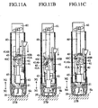
- the lancet 2 When piercing of the skin Sk by the lancet 21 completes, as shown in FIG. 12A , the lancet 2 is detached from the housing 3 (the leading-end sleeve 31). The lancet device 2 can be detached as the lancet device 2 is moved relative to the housing 3 in the direction N1.
- the lancet device 2 When the lancet device 2 is moved relative to the housing 3 in the direction N1, the action of the claw 35 of the leading-end sleeve 3 on the retaining part 24 of the casing 20 is released. As a result, as shown in FIG. 12B , the retaining part 24 is displaced toward the internal side of the radial direction, which leads the flange 27A of the lancet 21 to engage with the recess 25. Accordingly, the lancet 21 is fixed in the casing 20, so that it becomes possible to prevent the puncture needle 27B from protruding from the casing 20, and the lancet device 2 can be detached and discarded safely and hygienically.
- the puncture device 1 can further adjust a piercing depth by regulating the rotation angle of the link member 40 by the cam mechanism without providing a mechanism of adjusting a piercing depth in the lancet device 2. Accordingly, a positional relation between the lancet 21 and the casing 20 can be same in both cases in which the lancet 21 is attached in the lancet holder 42, and in which the lancet 21 is detached from the lancet holder 42. Consequently, even if the puncture device 1 employing the cam mechanism uses the so-called safety lancet, it is possible to appropriately secure a function as the safety lancet, and to pierce a skin safely and hygienically.
- the puncture device according to the present invention employs a configuration which can adjust a piercing depth by adjusting the rotation angle of the link member, and such a configuration is not limited to the foregoing embodiment.
- the puncture device of the present invention can employ a configuration that a recess like a groove is provided in a control arm, and as a connecting element like a pin fixed to a link member, or a connecting element like a pin to be engaged with the link member engages with the recess, the rotation angle of the link member can be adjusted in accordance with a position of the control arm.
- the rotation angle of the link member (the distance between the fixed shaft and the engaging pin) may be regulated by displacing the engaging position of the engaging pin relative to the link member in a direction inclined to the piercing direction N1 and the evacuating direction N2.
- the groove 41A of the moving member 41 may have the bending part 41Ab with both ends thereof being connected by a straight line part Ac extending in the directions N1 and N2.
- steps are provided between an upper end of the straight line part 41Ac and the bending part 41Ab, and the upper end of the straight line 41 Ac and the bending part 41Ab. Accordingly, the engaging pin 62 is prohibited from moving from an upper end of the bending part 41Ab to the upper end of the straight line part 41Ac in the groove 41A, or from a lower end of the straight line part 41Ac to a lower end of the bending part 41Ab. As a result, the engaging pin 62 moves through the groove 41A in a counterclockwise direction in the figures. Moreover, the engaging pin 62 moves through the straight line part 41Ac when the moving member 41 is moved relative to the housing 3 in the evacuating direction N2 (when the moving member 41 is latched to the housing 3).
- the lancet holder 42 when the moving member 41 is latched to the housing, the lancet holder 42 is prohibited from moving in the piercing direction N1 or in the evacuating direction N2 relative to the housing 3. Accordingly, even if the lancet holder 42 is engaged with the housing 3 after the lancet 27 (the puncture needle 27B) is attached in the lancet holder 42, a position of the lancet 27 (the puncture needle 27B) does not move in the piercing direction N1 or in the evacuating direction N2.
- the present invention can be further applicable to a puncture device employing a lancet other than the safety lancet.
Landscapes
- Health & Medical Sciences (AREA)
- Life Sciences & Earth Sciences (AREA)
- Heart & Thoracic Surgery (AREA)
- Surgery (AREA)
- Biophysics (AREA)
- Pathology (AREA)
- Engineering & Computer Science (AREA)
- Biomedical Technology (AREA)
- Hematology (AREA)
- Medical Informatics (AREA)
- Molecular Biology (AREA)
- Physics & Mathematics (AREA)
- Animal Behavior & Ethology (AREA)
- General Health & Medical Sciences (AREA)
- Public Health (AREA)
- Veterinary Medicine (AREA)
- Dermatology (AREA)
- Measurement Of The Respiration, Hearing Ability, Form, And Blood Characteristics Of Living Organisms (AREA)
- Surgical Instruments (AREA)
Claims (10)
- Punktionsvorrichtung (1) zum Bewegen eines Punktionselements (27B) in einer Stechrichtung in Richtung einer Zielstelle und zum Stechen der Zielstelle mit dem Punktionselement (27B), die Punktionsvorrichtung (1) mit:einem ersten Element (41), das in der Stechrichtung und in einer der Stechrichtung entgegengesetzten Rückzugsrichtung bewegbar ist;einem zweiten Element (42), das zum Zurückhalten des Punktionselements (27B) ist und das in der Stechrichtung und in der Rückzugsrichtung bewegbar ist; undeinem dritten Element (40), das sich während sich das erste Element (41) bewegt dreht und zum Bewegen des zweiten Elements (42) über eine Drehbewegung in der Stechrichtung und in der Rückzugsrichtung ist, die Punktionsvorrichtung (1) des Weiteren mit:einem Stechtiefeneinstellmechanismus (6) zum Einstellen einer Stechtiefe des Punktionselements (27B) an der Zielstelle durch Einstellen eines Rotationswinkels des dritten Elements (40),dadurch gekennzeichnet, dassder Stechtiefeneinstellmechanismus (6) ein Eingriffsteil (62) zum Eingriff mit dem dritten Element (40) aufweist und ein Verschiebungselement (60) zum Verschieben einer Eingriffsposition des Eingriffsteils (62) in dem dritten Element (40) aufweist,das erste Element (41) eine Aussparung (41A) mit einem Neigungsteil (41Ab) aufweist, der relativ zu der Stechrichtung und der Rückführrichtung geneigt ist, unddas Eingriffsteil (62) in das erste Element (41) bei der Aussparung (41A) eingreift.
- Punktionsvorrichtung nach Anspruch 1, bei der der Stechtiefeneinstellmechanismus des Weiteren ein Bedienelement (61) zum Einstellen einer Position des Verschiebungselements (60) aufweist.
- Punktionsvorrichtung nach Anspruch 2, bei der der Stechtiefeneinstellmechanismus ein Vorsprungsteil (63) aufweist, das an dem Verschiebungselement (60) oder dem Bedienelement (61) bereitgestellt ist, und eine Aussparung (64), die an dem jeweils anderen Element bereitgestellt ist, und
das Vorsprungsteil (63) und die Aussparung (64) miteinander in Eingriff sind und eine zueinander veränderbare relative Position aufweisen. - Punktionsvorrichtung nach Anspruch 2, bei der das Bedienelement zum Einstellen der Position des Verschiebungselements durch eine Drehbetätigung ist.
- Punktionsvorrichtung nach Anspruch 2, bei der ein Bewegungsausmaß des Verschiebungselements (60) relativ zu einem Betätigungsausmaß des Bedienelements (61) in einem nichtlinearen Verhältnis zueinander stehen.
- Punktionsvorrichtung nach Anspruch 1, bei der das Verschiebungselement (60) zum Verschieben einer Eingriffsposition des Eingriffsteils in dem dritten Element in der Stechrichtung und in der Rückzugrichtung ist.
- Punktionsvorrichtung nach Anspruch 1, bei der das dritte Element (40) eine Rotationsachse (40C) mit einer feststehenden Position, ein bewegliches Teil (40B), das um die Drehachse drehbar ist und bewirkt, dass ein zweites Element (42) sich relativ zu einer Drehbewegung des dritten Elements (40) folgend zu bewegen, und ein Loch zum Ermöglichen einer Positionsveränderung des Eingriffsteils aufweist.
- Punktionsvorrichtung nach Anspruch 1, bei der
der Neigungsteil ein gebogener Teil ist, der einen ersten Neigungsteil und einen zweiten Neigungsteil aufweist, die in unterschiedlichen Richtungen geneigt sind und durchgehend miteinander verbunden sind, und
die Aussparung des Weiteren einen geradlinigen Teil aufweist, der sich in der Stechrichtung und der Rückzugsrichtung erstreckt und beide Enden des gebogenen Teils miteinander verbindet. - Punktionsvorrichtung nach Anspruch 8, des Weiteren mit einem Gehäuse zum Aufnehmen des ersten bis dritten Elements, wobei
das erste Element mit dem Gehäuse in Eingriff ist, während das erste Element relativ zu dem Gehäuse in der Rückzugsrichtung bewegt wird und durch Lösen einer Verrastung/Arretierung für eine Bewegung des zweiten Elements in der Stechrichtung ist, und
sich das Eingriffsteil durch den geradlinigen Teil bewegt, wenn das erste Element in der Rückzugsrichtung relativ zu dem Gehäuse bewegt wird. - Punktionsvorrichtung nach Anspruch 1, des Weiteren mit einem Gehäuse zum Aufnehmen des ersten Elements, des zweiten Elements und des dritten Elements, wobei
mit dem Punktionselement in einer Verkleidung zurückgehalten das Punktionselement, wenn in dem Gehäuse angebracht, in dem zweiten Element zurückgehalten wird, und wenn die Verkleidung von dem Gehäuse gelöst wird, das Punktionselement von dem zweiten Element gelöst wird und in der Verkleidung gebunden ist, um einem Vorstehen eines Führungsendes des Punktionselements von der Verkleidung vorzubeugen.
Applications Claiming Priority (2)
| Application Number | Priority Date | Filing Date | Title |
|---|---|---|---|
| JP2007306666 | 2007-11-27 | ||
| PCT/JP2008/071588 WO2009069720A1 (ja) | 2007-11-27 | 2008-11-27 | 穿刺装置 |
Publications (3)
| Publication Number | Publication Date |
|---|---|
| EP2221000A1 EP2221000A1 (de) | 2010-08-25 |
| EP2221000A4 EP2221000A4 (de) | 2011-09-07 |
| EP2221000B1 true EP2221000B1 (de) | 2012-09-19 |
Family
ID=40678611
Family Applications (1)
| Application Number | Title | Priority Date | Filing Date |
|---|---|---|---|
| EP08853790A Active EP2221000B1 (de) | 2007-11-27 | 2008-11-27 | Punktionsvorrichtung |
Country Status (5)
| Country | Link |
|---|---|
| US (1) | US8308747B2 (de) |
| EP (1) | EP2221000B1 (de) |
| JP (1) | JP5341773B2 (de) |
| CN (1) | CN101877997B (de) |
| WO (1) | WO2009069720A1 (de) |
Families Citing this family (11)
| Publication number | Priority date | Publication date | Assignee | Title |
|---|---|---|---|---|
| CA2793226C (en) | 2010-04-09 | 2018-02-13 | Facet Technologies, Llc | Lancing device with tethered depth-control mechanism |
| US9167992B2 (en) * | 2010-11-03 | 2015-10-27 | Roche Diabetes Care, Inc. | Lancet drive system depth control method and test strip location methods |
| US8852123B2 (en) | 2010-12-30 | 2014-10-07 | Roche Diagnostics Operations, Inc. | Handheld medical diagnostic devices housing with sample transfer |
| US8158428B1 (en) | 2010-12-30 | 2012-04-17 | General Electric Company | Methods, systems and apparatus for detecting material defects in combustors of combustion turbine engines |
| US20120172757A1 (en) * | 2010-12-30 | 2012-07-05 | Roche Diagnostics Operations, Inc. | Handheld Medical Diagnostic Devices Housing Lancet Structures |
| US9717452B2 (en) | 2010-12-30 | 2017-08-01 | Roche Diabetes Care, Inc. | Handheld medical diagnostic devices with lancing speed control |
| GB2489740A (en) | 2011-04-08 | 2012-10-10 | Owen Mumford Ltd | Means for securely retaining a lancet in a lancing device |
| EP2836124B1 (de) * | 2012-04-11 | 2016-06-08 | Facet Technologies, LLC | Lanzettenvorrichtung mit tiefeneinstellung mit einer beweglichen achse |
| US9000866B2 (en) | 2012-06-26 | 2015-04-07 | University Of Dayton | Varactor shunt switches with parallel capacitor architecture |
| CN108698239B (zh) * | 2016-02-25 | 2021-06-01 | 奥林巴斯株式会社 | 操纵器系统及其控制方法 |
| CN112244953B (zh) * | 2020-10-08 | 2024-05-07 | 王洪奎 | 用于自动穿刺的机器手 |
Family Cites Families (10)
| Publication number | Priority date | Publication date | Assignee | Title |
|---|---|---|---|---|
| DE4212315A1 (de) | 1992-04-13 | 1993-10-14 | Boehringer Mannheim Gmbh | Blutlanzettenvorrichtung zur Entnahme von Blut für Diagnosezwecke |
| DE10121883A1 (de) * | 2001-05-05 | 2002-11-07 | Roche Diagnostics Gmbh | Blutentnahmesystem |
| JP4296035B2 (ja) | 2003-05-21 | 2009-07-15 | アークレイ株式会社 | 穿刺装置 |
| JP4761701B2 (ja) | 2003-05-21 | 2011-08-31 | アークレイ株式会社 | 穿刺深さを調整可能な穿刺装置 |
| JP2005312763A (ja) | 2004-04-30 | 2005-11-10 | Arkray Inc | 穿刺針カートリッジ、穿刺器具、先端ユニットおよびアダプタ |
| JP2006055190A (ja) * | 2004-08-17 | 2006-03-02 | Arkray Inc | 穿刺装置 |
| DE102004059491B4 (de) * | 2004-12-10 | 2008-11-06 | Roche Diagnostics Gmbh | Lanzettenvorrichtung zum Erzeugen einer Einstichwunde und Lanzettenantriebs-Baugruppe |
| US20070100256A1 (en) * | 2005-10-28 | 2007-05-03 | Sansom Gordon G | Analyte monitoring system with integrated lancing apparatus |
| US20070100364A1 (en) | 2005-10-28 | 2007-05-03 | Sansom Gordon G | Compact lancing apparatus |
| EP1797822A1 (de) * | 2005-12-15 | 2007-06-20 | Roche Diagnostics GmbH | Stechsystem zur Entnahme einer Körperflüssigkeit |
-
2008
- 2008-11-27 US US12/734,841 patent/US8308747B2/en active Active
- 2008-11-27 CN CN2008801180733A patent/CN101877997B/zh active Active
- 2008-11-27 JP JP2009543858A patent/JP5341773B2/ja active Active
- 2008-11-27 EP EP08853790A patent/EP2221000B1/de active Active
- 2008-11-27 WO PCT/JP2008/071588 patent/WO2009069720A1/ja active Application Filing
Also Published As
| Publication number | Publication date |
|---|---|
| CN101877997A (zh) | 2010-11-03 |
| EP2221000A1 (de) | 2010-08-25 |
| EP2221000A4 (de) | 2011-09-07 |
| WO2009069720A1 (ja) | 2009-06-04 |
| US20100312266A1 (en) | 2010-12-09 |
| JPWO2009069720A1 (ja) | 2011-04-14 |
| CN101877997B (zh) | 2012-07-25 |
| JP5341773B2 (ja) | 2013-11-13 |
| US8308747B2 (en) | 2012-11-13 |
Similar Documents
| Publication | Publication Date | Title |
|---|---|---|
| EP2221000B1 (de) | Punktionsvorrichtung | |
| JP4761701B2 (ja) | 穿刺深さを調整可能な穿刺装置 | |
| CN101912268B (zh) | 穿刺针筒 | |
| JP6420764B2 (ja) | 穿刺装置のねじり装填機構 | |
| US20070010841A1 (en) | Lancet assembly | |
| CN101166466B (zh) | 穿刺器具以及穿刺针筒 | |
| KR101375409B1 (ko) | 처치구 | |
| EP2010055B1 (de) | Stechvorrichtung mit unabhängigem antriebskern | |
| US20100036317A1 (en) | Handheld device for the local puncturing of a human or an animal skin, drive unit, needle unit and method for coupling | |
| EP2676693A1 (de) | Sicherheitsnadelanordnung | |
| JP2004344292A (ja) | 穿刺装置 | |
| WO2003005906A1 (fr) | Dispositif de perforation | |
| EP1901658B1 (de) | Hautpunktionssystem | |
| JP4507600B2 (ja) | 採血用穿刺器具、および穿刺針ユニット | |
| CN102883657B (zh) | 自动触发的穿刺辅助件 | |
| KR102117014B1 (ko) | 절단 생검기구 | |
| EP2823762B1 (de) | Anstechaktuator | |
| JP2005152620A (ja) | 穿刺装置 | |
| JP2006081751A (ja) | 針プロテクター付きランセット及びこれを装着する穿刺具 | |
| JP2011139920A (ja) | 穿刺深さを調整可能な穿刺装置 | |
| JP2010057954A (ja) | 穿刺装置 | |
| JP2005118458A (ja) | 医療用の注射針とともに使用する安全装置 |
Legal Events
| Date | Code | Title | Description |
|---|---|---|---|
| PUAI | Public reference made under article 153(3) epc to a published international application that has entered the european phase |
Free format text: ORIGINAL CODE: 0009012 |
|
| 17P | Request for examination filed |
Effective date: 20100610 |
|
| AK | Designated contracting states |
Kind code of ref document: A1 Designated state(s): AT BE BG CH CY CZ DE DK EE ES FI FR GB GR HR HU IE IS IT LI LT LU LV MC MT NL NO PL PT RO SE SI SK TR |
|
| AX | Request for extension of the european patent |
Extension state: AL BA MK RS |
|
| DAX | Request for extension of the european patent (deleted) | ||
| A4 | Supplementary search report drawn up and despatched |
Effective date: 20110804 |
|
| RIC1 | Information provided on ipc code assigned before grant |
Ipc: A61B 5/151 20060101AFI20110729BHEP |
|
| GRAP | Despatch of communication of intention to grant a patent |
Free format text: ORIGINAL CODE: EPIDOSNIGR1 |
|
| GRAS | Grant fee paid |
Free format text: ORIGINAL CODE: EPIDOSNIGR3 |
|
| GRAA | (expected) grant |
Free format text: ORIGINAL CODE: 0009210 |
|
| AK | Designated contracting states |
Kind code of ref document: B1 Designated state(s): AT BE BG CH CY CZ DE DK EE ES FI FR GB GR HR HU IE IS IT LI LT LU LV MC MT NL NO PL PT RO SE SI SK TR |
|
| REG | Reference to a national code |
Ref country code: GB Ref legal event code: FG4D |
|
| REG | Reference to a national code |
Ref country code: CH Ref legal event code: EP |
|
| REG | Reference to a national code |
Ref country code: IE Ref legal event code: FG4D |
|
| REG | Reference to a national code |
Ref country code: AT Ref legal event code: REF Ref document number: 575596 Country of ref document: AT Kind code of ref document: T Effective date: 20121015 |
|
| REG | Reference to a national code |
Ref country code: DE Ref legal event code: R096 Ref document number: 602008018898 Country of ref document: DE Effective date: 20121115 |
|
| PG25 | Lapsed in a contracting state [announced via postgrant information from national office to epo] |
Ref country code: CY Free format text: LAPSE BECAUSE OF FAILURE TO SUBMIT A TRANSLATION OF THE DESCRIPTION OR TO PAY THE FEE WITHIN THE PRESCRIBED TIME-LIMIT Effective date: 20120919 Ref country code: FI Free format text: LAPSE BECAUSE OF FAILURE TO SUBMIT A TRANSLATION OF THE DESCRIPTION OR TO PAY THE FEE WITHIN THE PRESCRIBED TIME-LIMIT Effective date: 20120919 Ref country code: NO Free format text: LAPSE BECAUSE OF FAILURE TO SUBMIT A TRANSLATION OF THE DESCRIPTION OR TO PAY THE FEE WITHIN THE PRESCRIBED TIME-LIMIT Effective date: 20121219 Ref country code: LT Free format text: LAPSE BECAUSE OF FAILURE TO SUBMIT A TRANSLATION OF THE DESCRIPTION OR TO PAY THE FEE WITHIN THE PRESCRIBED TIME-LIMIT Effective date: 20120919 Ref country code: HR Free format text: LAPSE BECAUSE OF FAILURE TO SUBMIT A TRANSLATION OF THE DESCRIPTION OR TO PAY THE FEE WITHIN THE PRESCRIBED TIME-LIMIT Effective date: 20120919 |
|
| REG | Reference to a national code |
Ref country code: NL Ref legal event code: VDEP Effective date: 20120919 |
|
| REG | Reference to a national code |
Ref country code: AT Ref legal event code: MK05 Ref document number: 575596 Country of ref document: AT Kind code of ref document: T Effective date: 20120919 |
|
| REG | Reference to a national code |
Ref country code: LT Ref legal event code: MG4D Effective date: 20120919 |
|
| PG25 | Lapsed in a contracting state [announced via postgrant information from national office to epo] |
Ref country code: SI Free format text: LAPSE BECAUSE OF FAILURE TO SUBMIT A TRANSLATION OF THE DESCRIPTION OR TO PAY THE FEE WITHIN THE PRESCRIBED TIME-LIMIT Effective date: 20120919 Ref country code: LV Free format text: LAPSE BECAUSE OF FAILURE TO SUBMIT A TRANSLATION OF THE DESCRIPTION OR TO PAY THE FEE WITHIN THE PRESCRIBED TIME-LIMIT Effective date: 20120919 Ref country code: SE Free format text: LAPSE BECAUSE OF FAILURE TO SUBMIT A TRANSLATION OF THE DESCRIPTION OR TO PAY THE FEE WITHIN THE PRESCRIBED TIME-LIMIT Effective date: 20120919 Ref country code: GR Free format text: LAPSE BECAUSE OF FAILURE TO SUBMIT A TRANSLATION OF THE DESCRIPTION OR TO PAY THE FEE WITHIN THE PRESCRIBED TIME-LIMIT Effective date: 20121220 |
|
| PG25 | Lapsed in a contracting state [announced via postgrant information from national office to epo] |
Ref country code: CZ Free format text: LAPSE BECAUSE OF FAILURE TO SUBMIT A TRANSLATION OF THE DESCRIPTION OR TO PAY THE FEE WITHIN THE PRESCRIBED TIME-LIMIT Effective date: 20120919 Ref country code: RO Free format text: LAPSE BECAUSE OF FAILURE TO SUBMIT A TRANSLATION OF THE DESCRIPTION OR TO PAY THE FEE WITHIN THE PRESCRIBED TIME-LIMIT Effective date: 20120919 Ref country code: EE Free format text: LAPSE BECAUSE OF FAILURE TO SUBMIT A TRANSLATION OF THE DESCRIPTION OR TO PAY THE FEE WITHIN THE PRESCRIBED TIME-LIMIT Effective date: 20120919 Ref country code: ES Free format text: LAPSE BECAUSE OF FAILURE TO SUBMIT A TRANSLATION OF THE DESCRIPTION OR TO PAY THE FEE WITHIN THE PRESCRIBED TIME-LIMIT Effective date: 20121230 Ref country code: NL Free format text: LAPSE BECAUSE OF FAILURE TO SUBMIT A TRANSLATION OF THE DESCRIPTION OR TO PAY THE FEE WITHIN THE PRESCRIBED TIME-LIMIT Effective date: 20120919 Ref country code: IS Free format text: LAPSE BECAUSE OF FAILURE TO SUBMIT A TRANSLATION OF THE DESCRIPTION OR TO PAY THE FEE WITHIN THE PRESCRIBED TIME-LIMIT Effective date: 20130119 Ref country code: BE Free format text: LAPSE BECAUSE OF FAILURE TO SUBMIT A TRANSLATION OF THE DESCRIPTION OR TO PAY THE FEE WITHIN THE PRESCRIBED TIME-LIMIT Effective date: 20120919 |
|
| PG25 | Lapsed in a contracting state [announced via postgrant information from national office to epo] |
Ref country code: SK Free format text: LAPSE BECAUSE OF FAILURE TO SUBMIT A TRANSLATION OF THE DESCRIPTION OR TO PAY THE FEE WITHIN THE PRESCRIBED TIME-LIMIT Effective date: 20120919 Ref country code: PL Free format text: LAPSE BECAUSE OF FAILURE TO SUBMIT A TRANSLATION OF THE DESCRIPTION OR TO PAY THE FEE WITHIN THE PRESCRIBED TIME-LIMIT Effective date: 20120919 Ref country code: PT Free format text: LAPSE BECAUSE OF FAILURE TO SUBMIT A TRANSLATION OF THE DESCRIPTION OR TO PAY THE FEE WITHIN THE PRESCRIBED TIME-LIMIT Effective date: 20130121 |
|
| PG25 | Lapsed in a contracting state [announced via postgrant information from national office to epo] |
Ref country code: AT Free format text: LAPSE BECAUSE OF FAILURE TO SUBMIT A TRANSLATION OF THE DESCRIPTION OR TO PAY THE FEE WITHIN THE PRESCRIBED TIME-LIMIT Effective date: 20120919 |
|
| REG | Reference to a national code |
Ref country code: CH Ref legal event code: PL |
|
| PLBE | No opposition filed within time limit |
Free format text: ORIGINAL CODE: 0009261 |
|
| STAA | Information on the status of an ep patent application or granted ep patent |
Free format text: STATUS: NO OPPOSITION FILED WITHIN TIME LIMIT |
|
| PG25 | Lapsed in a contracting state [announced via postgrant information from national office to epo] |
Ref country code: DK Free format text: LAPSE BECAUSE OF FAILURE TO SUBMIT A TRANSLATION OF THE DESCRIPTION OR TO PAY THE FEE WITHIN THE PRESCRIBED TIME-LIMIT Effective date: 20120919 Ref country code: BG Free format text: LAPSE BECAUSE OF FAILURE TO SUBMIT A TRANSLATION OF THE DESCRIPTION OR TO PAY THE FEE WITHIN THE PRESCRIBED TIME-LIMIT Effective date: 20121219 Ref country code: CH Free format text: LAPSE BECAUSE OF NON-PAYMENT OF DUE FEES Effective date: 20121130 Ref country code: LI Free format text: LAPSE BECAUSE OF NON-PAYMENT OF DUE FEES Effective date: 20121130 |
|
| 26N | No opposition filed |
Effective date: 20130620 |
|
| REG | Reference to a national code |
Ref country code: IE Ref legal event code: MM4A |
|
| REG | Reference to a national code |
Ref country code: DE Ref legal event code: R097 Ref document number: 602008018898 Country of ref document: DE Effective date: 20130620 |
|
| PG25 | Lapsed in a contracting state [announced via postgrant information from national office to epo] |
Ref country code: IE Free format text: LAPSE BECAUSE OF NON-PAYMENT OF DUE FEES Effective date: 20121127 |
|
| PG25 | Lapsed in a contracting state [announced via postgrant information from national office to epo] |
Ref country code: MT Free format text: LAPSE BECAUSE OF FAILURE TO SUBMIT A TRANSLATION OF THE DESCRIPTION OR TO PAY THE FEE WITHIN THE PRESCRIBED TIME-LIMIT Effective date: 20120919 |
|
| PG25 | Lapsed in a contracting state [announced via postgrant information from national office to epo] |
Ref country code: MC Free format text: LAPSE BECAUSE OF NON-PAYMENT OF DUE FEES Effective date: 20121130 Ref country code: TR Free format text: LAPSE BECAUSE OF FAILURE TO SUBMIT A TRANSLATION OF THE DESCRIPTION OR TO PAY THE FEE WITHIN THE PRESCRIBED TIME-LIMIT Effective date: 20120919 |
|
| PG25 | Lapsed in a contracting state [announced via postgrant information from national office to epo] |
Ref country code: LU Free format text: LAPSE BECAUSE OF NON-PAYMENT OF DUE FEES Effective date: 20121127 |
|
| PG25 | Lapsed in a contracting state [announced via postgrant information from national office to epo] |
Ref country code: HU Free format text: LAPSE BECAUSE OF FAILURE TO SUBMIT A TRANSLATION OF THE DESCRIPTION OR TO PAY THE FEE WITHIN THE PRESCRIBED TIME-LIMIT Effective date: 20081127 |
|
| REG | Reference to a national code |
Ref country code: FR Ref legal event code: PLFP Year of fee payment: 8 |
|
| REG | Reference to a national code |
Ref country code: FR Ref legal event code: PLFP Year of fee payment: 9 |
|
| REG | Reference to a national code |
Ref country code: FR Ref legal event code: PLFP Year of fee payment: 10 |
|
| PGFP | Annual fee paid to national office [announced via postgrant information from national office to epo] |
Ref country code: GB Payment date: 20231123 Year of fee payment: 16 |
|
| PGFP | Annual fee paid to national office [announced via postgrant information from national office to epo] |
Ref country code: IT Payment date: 20231124 Year of fee payment: 16 Ref country code: FR Payment date: 20231120 Year of fee payment: 16 Ref country code: DE Payment date: 20231121 Year of fee payment: 16 |