EP2220925B1 - Véhicule de travail agricole et unité d'affichage correspondante - Google Patents
Véhicule de travail agricole et unité d'affichage correspondante Download PDFInfo
- Publication number
- EP2220925B1 EP2220925B1 EP09170184.7A EP09170184A EP2220925B1 EP 2220925 B1 EP2220925 B1 EP 2220925B1 EP 09170184 A EP09170184 A EP 09170184A EP 2220925 B1 EP2220925 B1 EP 2220925B1
- Authority
- EP
- European Patent Office
- Prior art keywords
- display unit
- operating parameter
- parameter
- value
- variation
- Prior art date
- Legal status (The legal status is an assumption and is not a legal conclusion. Google has not performed a legal analysis and makes no representation as to the accuracy of the status listed.)
- Active
Links
- 230000008859 change Effects 0.000 claims description 39
- 238000004140 cleaning Methods 0.000 claims description 20
- 238000003860 storage Methods 0.000 claims description 4
- 230000004044 response Effects 0.000 claims description 2
- 238000000034 method Methods 0.000 description 10
- 238000005457 optimization Methods 0.000 description 8
- 239000010902 straw Substances 0.000 description 8
- 238000005520 cutting process Methods 0.000 description 6
- 230000008569 process Effects 0.000 description 6
- 238000003306 harvesting Methods 0.000 description 5
- 230000006872 improvement Effects 0.000 description 5
- 230000000694 effects Effects 0.000 description 4
- 230000006870 function Effects 0.000 description 4
- 230000033001 locomotion Effects 0.000 description 4
- 238000002360 preparation method Methods 0.000 description 4
- 241001124569 Lycaenidae Species 0.000 description 2
- 230000005540 biological transmission Effects 0.000 description 2
- 230000015572 biosynthetic process Effects 0.000 description 2
- 230000000052 comparative effect Effects 0.000 description 2
- 230000001419 dependent effect Effects 0.000 description 2
- 210000005069 ears Anatomy 0.000 description 2
- 238000005516 engineering process Methods 0.000 description 2
- 230000003287 optical effect Effects 0.000 description 2
- 238000004393 prognosis Methods 0.000 description 2
- 230000009471 action Effects 0.000 description 1
- 238000010009 beating Methods 0.000 description 1
- 230000008021 deposition Effects 0.000 description 1
- 230000006866 deterioration Effects 0.000 description 1
- 238000009826 distribution Methods 0.000 description 1
- 238000002594 fluoroscopy Methods 0.000 description 1
- 239000004459 forage Substances 0.000 description 1
- 239000000446 fuel Substances 0.000 description 1
- 230000005484 gravity Effects 0.000 description 1
- 239000012535 impurity Substances 0.000 description 1
- 230000003993 interaction Effects 0.000 description 1
- 238000005259 measurement Methods 0.000 description 1
- 230000003534 oscillatory effect Effects 0.000 description 1
- 230000000737 periodic effect Effects 0.000 description 1
- 238000011084 recovery Methods 0.000 description 1
- 230000009467 reduction Effects 0.000 description 1
- 238000000926 separation method Methods 0.000 description 1
Images


Classifications
-
- A—HUMAN NECESSITIES
- A01—AGRICULTURE; FORESTRY; ANIMAL HUSBANDRY; HUNTING; TRAPPING; FISHING
- A01D—HARVESTING; MOWING
- A01D41/00—Combines, i.e. harvesters or mowers combined with threshing devices
- A01D41/12—Details of combines
- A01D41/127—Control or measuring arrangements specially adapted for combines
Definitions
- the present invention relates to a display unit for an agricultural work vehicle according to the preamble of claim 1 and an agricultural work vehicle, in particular a combine harvester, in which such a display unit is used.
- Agricultural work vehicles such as tractors, combine harvesters, forage harvesters, etc.
- Agricultural work vehicles such as tractors, combine harvesters, forage harvesters, etc.
- the function and / or the work result of individual working units or a plurality of cooperating working units are essentially dependent on the correct definition of the setting parameters of the individual units.
- the relationship between setting parameters of the units and the work result is complicated and often non-linear, so that it is difficult to estimate for an automatic control and also for a skilled operator in a particular case, as a change made by him to one or more setting parameters of the working machine the work result will affect.
- a display unit for displaying operating parameters, which are displayed in the form of a pie chart. Changes in a value of an operating parameter lead to a positional increase of the pie segment representing the operating parameter.
- the display unit is configured to represent the change in the operating parameter by simultaneously displaying a value of the operating parameter before the change (qalt) and a value of the operating parameter after the change (qist), the operator can relate the change directly to the amount of the operating parameter and thus better assess the relevance of a change.
- a change tendency of the operating parameter is made immediately apparent, in that a first figure assigned to the operating parameter and shown on the display element adopts two discrete values of a given property depending on the sign of the change.
- this property is the color or fill pattern of the first figure.
- the operator By displaying a second figure whose dimension is representative of the smaller one of said values of the operating parameter, the operator is enabled to estimate the change in the operating parameter relative to its magnitude.
- the dimension can be a length; then it is expedient to display the figures in the direction of the length next to one another on the display unit, so that the total length of the two figures corresponds to the larger of the two values of the operating parameter.
- the figures are expediently shown adjacent to each other on the display unit, so that the common outline of both figures corresponds to the larger of the two values of the operating parameter.
- the common outline of the two figures is advantageously similar to the second figure.
- the display unit is expediently connected to at least one sensor, the measured values of the operating parameter or at least values which are a calculation of the Enable operating parameters in real time.
- a value to be set for at least one parameter influencing the operating parameter of the vehicle can be entered by the operator via an operating element, and the display unit is set up to display that change in the operating parameter resulting from a change in the at least one setting parameter entered on the operating element.
- the display unit is set up to display that change in the operating parameter resulting from a change in the at least one setting parameter entered on the operating element.
- the display unit expediently comprises a memory element for storing the value of the operating parameter at the time of the input of the change of the setting parameter on the operating element.
- the display unit is also configured to make a change of a setting parameter on a working unit of the work vehicle.
- it may reset to this original value in response to a reset command from the operator. Therefore, it is not necessary for the operator to remember the original value of each changed setting parameter, and then to be able to adjust it quantitatively if necessary; it is enough to simply enter the desire of the operator after recovery of the initial state, no matter which setting parameter values correspond to it.
- the display unit If the operator has not undone a setting parameter change after a certain time, it can be assumed that he wants to keep it. In this case, or even at the express command of the operator, it is expedient for the display unit to replace the stored value of the setting parameter with the changed value, so that the latter can be readjusted if a subsequent renewed change is unsuccessful.
- the control unit If the value of the operating parameter has been stored, it is expedient in the control unit to block the value of this parameter again during a predetermined period of time or until the user enters a release command.
- the lock allows the operator to vary within the given time period also several adjustment parameters in order to observe the effect of such a combined change on the operating parameter can.
- a reset command of the operator expediently has an effect on all stored setting parameter values, so that even in such a case the entirety of the setting parameters which have given the stored value of the operating parameter can be exactly restored.
- One Release command by the operator is expediently given when a change of a setting parameter has led to an improvement of the operating parameter and the resulting new value of the operating parameter is to be used as a reference for the further optimization.
- the invention further relates to an agricultural work vehicle, in particular a combine harvester, with a display unit of the type described above.
- a working aggregate, to which the one or more adjustment parameters relate may be selected in a combine harvester, in particular under concave, sieve and cleaning blower and the setting parameters under concave width, strainer basket width and blower output.
- operating parameters are representative in particular for the working quality of the work vehicle representative parameters such as the harvest performance or, in the case of a combine, grain loss, fraction fraction and amount of tailings.
- a schematic side view of an agricultural working vehicle designed as a combine harvester 1 is shown.
- the task of a combine harvester 1 is to pick up crops growing on stalks from a processing surface 32 and separate them from the straw and other admixtures.
- a grain cutter 2 shown. This cuts the Ernteguthalme with the crop located in the crop from the processing surface 32 and then performs it on the width of the feeder conveyor 3 serving as intake.
- the feederhouse 3 are circumferential feeder chains 4 with transverse webs, which feed the crop to the downstream threshing 5.6.
- the crop is taken from the Vorbevantertrommel 5 at the end of the inclined conveyor 3 and accelerated along the circumference of Vorbeschreibertrommel 5 between the Vorbeschreibertrommel 5 and the concave 8.
- the accelerated crop is then transferred to the threshing drum 6 and further accelerated.
- the crop acting centrifugal force By the beating and rubbing action of Vorbeschreibertrommel 5 and the threshing drum 6 and on The crop acting centrifugal force, the crop is separated from the ears and straw and then passes through the permeable to the crop concave 8 on the preparation floor 27.
- the discharged from the threshing drum 6 straw is braked by a turning drum 7 and several over the working width side by side arranged shakers 9 deflected.
- the oscillating movement of the shakers 9 and their step-shaped formation effect a promotion of the straw to the rear end of the combine and a separation of the crop still in the straw. This residual amount is also transferred to the preparation tray 27 by a swing
- the transfer takes place via a blown by the cleaning fan 24 case 34 on the upper sieve 10.
- This and the underlying Untersieb 11 are usually lamellae with each separately adjustable opening widths, the upper sieve 10 can be set in a rear area with a different opening width as in its front area.
- the upper and Untersieb 10,11 are penetrated by a generated by the cleaning fan 24 air flow.
- the oscillatory movement of the sieves 10,11 and the air flow cause a promotion of the crop and the admixtures to the rear end of the harvester out.
- level 34 Large and light impurities from the air stream before reaching the top wire 10 are detected and separated from the combine 1. Depending on the setting of the upper wire width, fall the individual Erntegutkörner and other components of the crop through this and thus reach the lower sieve 11. Straw and not threshed ears are moved across the front wire area and fall in the rear of the upper wire 10 through the upper wire 10 directly into the so-called tailings.
- the lower wire 11 usually has a finer screen blade structure than the upper wire 10 and is normally set with a smaller opening than the upper wire 10.
- Erntegut Larger and lighter Erntegut soner, such as Erntegutkörner with spelled, ear parts or handle parts are, if they are passed through the upper wire 10 on the lower wire 11, passed through the swinging motion and the air flow in the so-called tailings.
- the cleaned crop itself falls directly through the lower sieve 11 and is conveyed by means of a feed screw and a grain elevator 13 into a grain tank 33.
- the harvested crop has been returned to the threshing process by means of a feed screw and a tailings elevator 12 above the pre-accelerating drum 5.
- the combine harvester 1 is equipped with a driver's cab 35, in which a display screen 29 and a control unit 30 with integrated storage unit are arranged. Furthermore, there are no closer illustrated, known to those skilled device for specifying the direction of travel and speed of the combine 1 available.
- the display screen 29 and the control unit 30 communicate with individual sensors and actuators arranged at different locations in the combine harvester 1. The operator of the combine harvester 1 thus obtains the possibility of being able to set and monitor setting parameters of the individual working aggregates and thus the mode of operation of the combine harvester 1.
- the individual points in the combine harvester 1 are indicated by arrowheads, on which a sensor for determining process and setting parameters is arranged.
- a vehicle speed measuring device 23 On the drive axle of the combine 1, a vehicle speed measuring device 23 is arranged, which detects the respective driving speed.
- the cutting unit 2 is assigned a cutting height measuring device 22. This serves to determine the actual distance between the cutting unit 2 and the processing surface 32.
- the sensed value can be displayed to the operator by means of the display unit 29 and also used as an actual value for automatic cutting height control.
- a crop amount measuring device 20 is mounted in the feederhouse 3. This determines the dependent on the harvest amount deflection of the feed chain. 4
- This threshing width measuring device 21 is simple or multiple and determines the distance between the Vorbeschreibertrommel 5 and the concave 8 and / or the threshing cylinder 6 and the concave 8 at one or more locations.
- the Vorbe instructertrommel 5, the threshing drum 6 and the turning drum 7 are usually driven by a common drive, wherein the rotational speeds of the drums 5,6,7 can be varied via an actuator.
- These drums 5, 6, 7 are assigned a threshing drum rotational speed measuring device 31 for detecting at least one of the drum rotational speeds.
- the drive of the cleaning fan 24 is designed variable speed.
- the actual speed of the cleaning fan 24 is detected by means of a cleaning blower measuring device 25.
- the cleaning device may be associated with other sensors. So can the respective
- this sensor technology is also used in the shakers 9 for detecting the deposition.
- a shaker loss sensor 19 is attached. This covers proportionately still at the end of the shaker 9 separated Erntegutkörner.
- a flapper sensor at the end of the lower wire 11 or on the Arrange position of return of tailings in the threshing process.
- a tailings measuring device 16 is arranged at the upper end of the tailings elevator 12. This determines the tailings volume, grain and broken grain content.
- the grain elevator 13 is equipped with further sensors 14,15, which allow the determination of the flow rate by a yield measuring system 14 and the determination of the specific gravity of the crop by a Kalibrierwaage 15.
- working unit is understood as meaning all components and / or control elements of an agricultural working vehicle which fulfill a specific function for achieving a work result of the working machine.
- These working units can the example of the combine harvester 1 exemplified the grain cutter 2, the feederhouse 3, the feeder chains 4, the Vorbenchertrommel 5, the threshing drum 6, the turning drum 7, the concave 8, the shaker 9, the upper sieve 10, the lower sieve 11, the tailings elevator 12, the grain elevator 13, the cleaning fan 24, the preparation floor 27 and / or the return floor 28 may be.
- a group of cooperating individual working aggregates are referred to as working aggregates in the sense of the invention.
- This can be, for example, the cleaning device of the combine harvester 1 formed by the top wire 10, the bottom wire 11 and the cleaning fan 24.
- the various sensors and measuring systems in the working machine such as the yield measuring system 14, the Kalibrierwaage 15, the Gönovamessincardi 16, the Obersieblesmess responded 17, the Obersiebweitenmess responded 18, the Schüttlernersensor 19, the harvest quantity measuring device 20, the threshing width measuring device 21, the cutting height measuring device 22, the driving speed measuring device 23, the cleaning blower measuring device 25, the sub-width measuring device 26 and / or the threshing drum rotational speed measuring device 31 are to be regarded as working units within the meaning of the invention.
- setting parameters are understood to mean any variables or properties of the agricultural machine or its working aggregates, to which the operator can influence directly, alone or also linked to other variables, in particular those quantities or properties that are important to them the control unit 30 is associated with a controller.
- First and foremost parameters that can be changed are continuously variable variables such as a speed, eg one of the drums 5, 6, 7 or the cleaning fan 24, a frequency, for example, the shaker 9, the sieves 10, 11 or the bottoms 27, 28 and / or a speed and / or distance and / or pressure and / or Erntegut malficientmenge one Work aggregates, to name but a few possibilities. But it can also be discrete variables, such as the on or off of an additional aggregate, etc ..
- operating parameters those parameters are preferably considered that are not in a clear relationship with the value of a single adjustment parameter, but can be influenced via various adjustment parameters.
- parameters are considered whose value is related to the quality of the product of the work or to the economic yield of the work vehicle's work, such as the purity of the crop, the fraction of broken grain, crop losses on the shaker 9 or top sieve 10, tailings, etc
- quantities derived from the above quantities taking into account external economic constraints may also be operating parameters, such as expected sales proceeds taking into account actual crop prices as a function of purity and fraction fraction, or taking into account machine operating and manpower costs thereof Sales proceeds derived net profit.
- "operator” means the person or a plurality of persons, may affect the setting parameters of the working machinery of an agricultural work vehicle and a measured value of one or more operating parameters is displayed. This may be the driver of the agricultural work vehicle itself and / or a driver of another agricultural work vehicle having authorized access to the control unit of the work vehicle to be adjusted by means of suitable transmission means and / or another group of persons such as a farmer from his farm computer communicates by means of suitable transmission means with the control unit of the work vehicle to be adjusted.
- This listing of possible operators is exemplary and not to be considered exhaustive.
- control unit 30 embodies the control unit according to the invention.
- An implementation in which, for example, the yard computer functions as a control unit will be apparent to those skilled in the art from the following explanations.
- Fig. 2 shows a flowchart of running on the control unit 30 working method.
- a first step S1 of the cyclically proceeding method is the determination of the current value q ist of an operating parameter q.
- the determination may be a direct measurement by a sensor, for example one of the sensors 14 to 17 or 19, or it may be a calculation based on results this and possibly other sensors and possibly additionally based on external boundary conditions such as acceptance prices, fuel costs, etc.
- the result of the calculation is displayed on the display screen 29 to the driver in step S2.
- the driver has the option of optimizing the operating parameter q by varying various setting parameters EP 1 ,..., EP n at the controllers of the control unit 30. Unless it does so, the control unit 30 remains in a normal operation mode in which the steps S1, S2 and a step S3 of checking whether the driver made an input for changing a setting parameter repeat cyclically.
- step S7 the control unit 30 activates an actuator assigned to the selected setting parameter EP i in order to set it to the value selected by the driver. Subsequently, as in step S1, the current value q ist of the operating parameter q is determined. Displaying both the value determined in step S8 qist the parameter q as well be, in step S4 a safe value q old in step S9 on the display screen 29th
- step S10 the control unit 30 checks whether there is a new operator input concerning the same setting parameter EP i or another setting parameter. If the input relates to the same setting parameter EP i , the method returns to step S6, in the case of another setting parameter EP j to step S5 to save the current value of this parameter. (Alternatively, when changing to the optimization mode of operation in step S5, the entirety of the setting parameters EP 1 , ..., EP n could be saved, then the process in step S10 could always return to step S6 in case of change regardless of the setting parameter.)
- step S11 If there is no input of the driver that is specific to an adjustment parameter, it is still checked in step S11 whether the driver has possibly actuated a reset button of the control unit 30. If the reset key is inoperative and it is determined in step S12 that the timer has not expired, the process checks the operation of a takeover key of the control unit 30 in step S13. If this is also inoperative, the process returns to step S8. By doing so, steps S8 through S13 are periodic be traversed, the driver is continuously displayed the current values of the parameter q, which change gradually as a result of the Einstellparameter selectedung. Based on a comparison of the displayed values q, q old , the driver can decide whether his input has led to an improvement of the operating parameter q or not.
- step S12 the expiry of the timer is detected
- the control unit 30 automatically returns to the normal operating mode, to step S1.
- the driver has the opportunity to press the enter key to signal that he wants to keep the change of the setting parameter EP i . If the control unit 30 recognizes this in step S13, it returns to step S1 already before the expiration of the timer. If the driver now makes another change of the same or another setting parameter, the value of the operating parameter q achieved at the time of this renewed change is saved by a renewed execution of step S4 and can serve as a comparative standard for further changes.
- step S11 it restores all previously saved values of the changed setting parameters EP i , EP j ,... In step S14, so that the state is restored before the beginning of the optimization attempt.
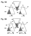
- Fig. 3a shows an example of a possible image that is displayed to the driver on the display screen 29 in the normal operating mode.
- Bright triangles 36, 37 represent display fields for grain losses detected by the shake loss sensor 19 and the upper sieve loss measuring means 17, respectively, as examples of operating parameters of the combine 1.
- the area of a black displayed triangle 38 or 39 in the lower left corner of the triangles 36, 37 is proportional to the actual measured actual losses.
- a black triangle 41 represents a tailings volume detected by the tailings measuring device 16 and an adjacent black bar 42 represents the tailings mass.
- Fig. 3b shows a display image of the display screen 29, which in the optimization mode of operation, starting from the in Fig. 3a values of grain losses, tailings volume and tailings by changing one or more adjustment parameters. Shaker loss improved.
- the black triangle 38 representing the current value of the shaker loss is reduced in size, and a bar 43 adjacent thereto appears in green color to make the progress conspicuous.
- the dark triangle and the bar 43 together occupy the same area as the triangle 38 in FIG Fig. 3a , That is, the stronger the improvement, the more green you can see.
- the changes may also be represented as numerical values, in percentages or in percentage points, whereby a negative sign in the case of shaker loss indicates the decrease in losses and a positive one in the case of upper sieve loss the increase.
- a corresponding display scheme is also used for the tailings parameters: next to a black triangle 46, which coincides with the triangle 41 of FIG Fig. 3a is equal in area, a red bar 47 indicates an increase in the tailings volume. At the same time, however, a reduction in the tailings mass has been achieved, so the black box 48 is in Fig. 3b smaller than the bar 42 of the Fig. 3a , and the field 48 as well an adjacent green field 49 shown in green occupy the area of the beam 42.
- the driver can see at a glance the color distribution on the display panel 29 whether a change in parameters has been advantageous and should be maintained, or if further changes are required or the optimization attempt should be canceled.
Claims (15)
- Unité d'affichage (29) pour un engin agricole (1) destinée à afficher au moins un paramètre d'exploitation (q) de l'engin, lequel paramètre est variable en fonction d'un ou plusieurs paramètres de réglage (EPi) de l'engin, l'unité d'affichage (29) étant agencée pour afficher une variation du paramètre d'exploitation (q) résultant d'une variation d'au moins un des paramètres de réglage (EPi) et pour visualiser la variation du paramètre d'exploitation (q) par une visualisation simultanée d'une valeur du paramètre d'exploitation avant la variation (qalt) et d'une valeur du paramètre d'exploitation après la variation (qist), caractérisée en ce que l'unité d'affichage (29) est agencée pour afficher une première figure (43 ; 45 ; 47 ; 49) dont une dimension est représentative de l'ampleur de la variation du paramètre d'exploitation et dont une propriété adopte deux valeurs discrètes selon le signe de la variation du paramètre d'exploitation, et une seconde figure (38 ; 44 ; 46 ; 48) dont la dimension est à chaque fois représentative de la plus petite desdites valeurs (qalt, qist).
- Unité d'affichage selon la revendication 1, caractérisée en ce que la propriété est la couleur ou un motif de surface de la première figure (43 ; 45 ; 47 ; 49).
- Unité d'affichage selon une des revendications 1 ou 2, caractérisée en ce que la dimension est une longueur des figures (48, 49) et, sur l'unité d'affichage (29), les figures sont affichées côte à côte dans le sens de la longueur.
- Unité d'affichage selon une des revendications 1 à 3, caractérisée en ce que la dimension est une surface des figures (38, 43 ; 44, 45 ; 46, 47) et, sur l'unité d'affichage (29), les figures (38, 43 ; 44, 45 ; 46, 47) sont affichées de façon contiguë les unes par rapport aux autres.
- Unité d'affichage selon une des revendications 1 à 4, caractérisée en ce que la forme des premières figures (38, 43 ; 44, 45 ; 46, 47) est identique à celle de la seconde figure.
- Unité d'affichage selon une des revendications précédentes, caractérisée en ce qu'elle est connectée à au moins un capteur (14, 16, 17, 18, 19, 20) pour déterminer la valeur instantanée (qist) du paramètre d'exploitation (q) et agencée pour actualiser en continu la variation affichée du paramètre d'exploitation (q) à l'aide de la valeur instantanée déterminée (qist) du paramètre d'exploitation.
- Unité d'affichage selon une des revendications précédentes, caractérisée en ce qu'elle est connectée à un élément d'utilisation par l'intermédiaire duquel une valeur pour au moins un paramètre de réglage (EPi) du véhicule influençant le paramètre d'exploitation (q) peut être entrée par un utilisateur, et en ce qu'elle est agencée pour afficher la variation du paramètre d'exploitation (q) résultant d'une variation du au moins un paramètre de réglage (EPi) entrée par l'intermédiaire de l'élément d'utilisation.
- Unité d'affichage selon la revendication, caractérisée par un élément de mémorisation pour mémoriser la valeur (qalt) du paramètre d'exploitation (q) au moment de l'entrée de la variation du paramètre de réglage (EPi) par l'intermédiaire de l'élément d'utilisation.
- Unité d'affichage selon la revendication 7, caractérisée en ce qu'elle est également agencée pour effectuer une modification d'un paramètre de réglage (EPi) au niveau d'un équipement de travail de l'engin, pour mémoriser une valeur initiale du paramètre de réglage (EPi) valable avant la modification et pour annuler, en réaction à la réception d'une instruction de réinitialisation (S14), la modification du paramètre de réglage effectuée au niveau de l'équipement de travail.
- Unité d'affichage selon la revendication 9, caractérisée en ce qu'elle est également agencée pour remplacer la valeur mémorisée du paramètre de réglage (EPi) par la valeur modifiée en réponse à une instruction de l'utilisateur (S13) ou après écoulement d'un temps d'attente (S12).
- Unité d'affichage selon la revendication 8, caractérisée en ce que, après la mémorisation de la valeur du paramètre d'exploitation, une nouvelle mémorisation de cette valeur est interdite pendant un laps de temps prédéfini (S12) ou jusqu'à l'entrée d'une instruction de validation (S13) par l'utilisateur.
- Engin agricole (1) comprenant une unité d'affichage (29) selon une des revendications précédentes.
- Engin agricole selon la revendication 12, caractérisé en ce qu'il s'agit d'une moissonneuse-batteuse.
- Engin agricole selon la revendication 13, caractérisé en ce que les un ou plusieurs paramètres de réglage (EPi) se réfèrent à au moins un équipement de travail choisi parmi le batteur (6), le contre-batteur (8), le tamis (10, 11), le ventilateur de nettoyage (24), et le paramètre de réglage est choisi parmi la vitesse de rotation de batteur, la largeur du contre-batteur, la largeur de tamis et la puissance du ventilateur.
- Engin agricole selon une des revendications 13 ou 14, caractérisé en ce que le paramètre d'exploitation (q) est choisi parmi le rendement de récolte, la perte de grain, la proportion de grains cassés et la quantité du retour à ôtons.
Applications Claiming Priority (1)
| Application Number | Priority Date | Filing Date | Title |
|---|---|---|---|
| DE102009009817A DE102009009817A1 (de) | 2009-02-20 | 2009-02-20 | Landwirtschaftliches Arbeitsfahrzeug und Steuereinheit dafür |
Publications (2)
| Publication Number | Publication Date |
|---|---|
| EP2220925A1 EP2220925A1 (fr) | 2010-08-25 |
| EP2220925B1 true EP2220925B1 (fr) | 2016-01-06 |
Family
ID=42289132
Family Applications (1)
| Application Number | Title | Priority Date | Filing Date |
|---|---|---|---|
| EP09170184.7A Active EP2220925B1 (fr) | 2009-02-20 | 2009-09-14 | Véhicule de travail agricole et unité d'affichage correspondante |
Country Status (4)
| Country | Link |
|---|---|
| US (1) | US8340862B2 (fr) |
| EP (1) | EP2220925B1 (fr) |
| DE (1) | DE102009009817A1 (fr) |
| RU (1) | RU2527759C2 (fr) |
Families Citing this family (74)
| Publication number | Priority date | Publication date | Assignee | Title |
|---|---|---|---|---|
| US10318138B2 (en) * | 2011-03-11 | 2019-06-11 | Intelligent Agricultural Solutions Llc | Harvesting machine capable of automatic adjustment |
| US10321624B2 (en) | 2011-03-11 | 2019-06-18 | Intelligent Agriculture Solutions LLC | Air seeder manifold system |
| US8930039B2 (en) * | 2012-06-11 | 2015-01-06 | Cnh Industrial America Llc | Combine performance evaluation tool |
| DE102013106128A1 (de) * | 2012-07-16 | 2014-06-12 | Claas Selbstfahrende Erntemaschinen Gmbh | Landwirtschaftliche Arbeitsmaschine mit zumindest einer Steuerungseinrichtung |
| US9078397B2 (en) * | 2012-11-16 | 2015-07-14 | Cnh Industrial America Llc | System for conveying agricultural material in a harvester |
| US8965640B2 (en) * | 2012-11-30 | 2015-02-24 | Caterpillar Inc. | Conditioning a performance metric for an operator display |
| US20140277960A1 (en) * | 2013-03-18 | 2014-09-18 | Deere & Company | Harvester with fuzzy control system for detecting steady crop processing state |
| US9826682B2 (en) * | 2013-03-18 | 2017-11-28 | Deere & Company | Operating state detection system for work machine with fusion considering sensor value reliability |
| US9345197B2 (en) * | 2013-05-10 | 2016-05-24 | Agco Corporation | Combine harvester with even crop distribution |
| RU2658981C2 (ru) * | 2013-06-18 | 2018-06-26 | Дир Энд Компани | Система выявления рабочего состояния для рабочей машины с объединением, учитывающим достоверность значений датчиков |
| EP3010327B1 (fr) * | 2013-06-21 | 2018-08-08 | Precision Planting LLC | Appareil de surveillance de rendement |
| DE102013107169A1 (de) * | 2013-07-08 | 2015-01-08 | Claas Selbstfahrende Erntemaschinen Gmbh | Landwirtschaftliche Erntemaschine |
| GB201322403D0 (en) * | 2013-12-18 | 2014-02-05 | Agco As | Combine harvester grain cleaning system |
| US10380704B2 (en) | 2014-01-14 | 2019-08-13 | Deere & Company | Operator performance recommendation generation |
| DE102014113008A1 (de) * | 2014-09-10 | 2016-03-10 | Claas Selbstfahrende Erntemaschinen Gmbh | Verfahren zum Betreiben eines Mähdreschers |
| EP3190866A4 (fr) | 2014-09-12 | 2018-05-02 | Intelligent Agricultural Solutions LLC | Capteur acoustique d'écoulement de matériau |
| US9901031B2 (en) * | 2014-09-24 | 2018-02-27 | Deere & Company | Automatic tuning of an intelligent combine |
| US9934538B2 (en) | 2014-09-24 | 2018-04-03 | Deere & Company | Recalling crop-specific performance targets for controlling a mobile machine |
| CN104737721B (zh) * | 2015-03-04 | 2016-08-31 | 江苏大学 | 一种联合收获机自适应清选控制装置及其自适应清选方法 |
| BE1022889B1 (nl) | 2015-05-29 | 2016-10-07 | Cnh Industrial Belgium Nv | controller voor een oogstmachine |
| JP6675843B2 (ja) * | 2015-09-02 | 2020-04-08 | 株式会社クボタ | コンバイン |
| US9999176B2 (en) | 2016-04-29 | 2018-06-19 | Cnh Industrial America Llc | Optical tailings sensor in tri-sweep tailings housing |
| UA127601C2 (uk) | 2016-11-01 | 2023-11-01 | Кінз Меньюфекчурінг, Інк. | Блоки керування, вузли, система і спосіб для передачі і обміну даними |
| US10028428B2 (en) * | 2016-12-07 | 2018-07-24 | Deere & Company | Control system and method for automatically determining characteristic for optimum machine performance |
| US11789413B2 (en) | 2017-06-19 | 2023-10-17 | Deere & Company | Self-learning control system for a mobile machine |
| US20180359917A1 (en) * | 2017-06-19 | 2018-12-20 | Deere & Company | Remote control of settings on a combine harvester |
| US11589507B2 (en) | 2017-06-19 | 2023-02-28 | Deere & Company | Combine harvester control interface for operator and/or remote user |
| US10694668B2 (en) | 2017-06-19 | 2020-06-30 | Deere & Company | Locally controlling settings on a combine harvester based on a remote settings adjustment |
| EP3438769B1 (fr) | 2017-08-01 | 2019-11-20 | Kverneland Group Mechatronics BV | Procédé pour commander le fonctionnement d'un terminal de commande utilisateur d'une machine agricole et machine agricole |
| DE102017121654A1 (de) | 2017-09-19 | 2019-03-21 | Claas Tractor Sas | Landwirtschaftliche Arbeitsmaschine |
| US11089727B2 (en) * | 2018-02-23 | 2021-08-17 | Macdon Industries | Harvesting machine with programmable inputs for header height and auxiliary function control |
| DE102018111077A1 (de) * | 2018-05-08 | 2019-11-14 | Claas Selbstfahrende Erntemaschinen Gmbh | Mähdrescher sowie Verfahren zum Betreiben eines Mähdreschers |
| US10782672B2 (en) | 2018-05-15 | 2020-09-22 | Deere & Company | Machine control system using performance score based setting adjustment |
| BE1026659B1 (nl) * | 2018-09-28 | 2020-04-29 | Cnh Ind Belgium Nv | Controller voor een landbouwoogstmachine |
| US11021053B2 (en) | 2018-10-12 | 2021-06-01 | Deere & Company | Work vehicle with commodity tank and a commodity tank for a work vehicle |
| USD920882S1 (en) | 2018-10-12 | 2021-06-01 | Deere & Company | Vehicle tank |
| US11079725B2 (en) | 2019-04-10 | 2021-08-03 | Deere & Company | Machine control using real-time model |
| US11589509B2 (en) | 2018-10-26 | 2023-02-28 | Deere & Company | Predictive machine characteristic map generation and control system |
| US11641800B2 (en) | 2020-02-06 | 2023-05-09 | Deere & Company | Agricultural harvesting machine with pre-emergence weed detection and mitigation system |
| US11178818B2 (en) | 2018-10-26 | 2021-11-23 | Deere & Company | Harvesting machine control system with fill level processing based on yield data |
| US11240961B2 (en) | 2018-10-26 | 2022-02-08 | Deere & Company | Controlling a harvesting machine based on a geo-spatial representation indicating where the harvesting machine is likely to reach capacity |
| US11672203B2 (en) | 2018-10-26 | 2023-06-13 | Deere & Company | Predictive map generation and control |
| US11653588B2 (en) | 2018-10-26 | 2023-05-23 | Deere & Company | Yield map generation and control system |
| US11467605B2 (en) | 2019-04-10 | 2022-10-11 | Deere & Company | Zonal machine control |
| US11957072B2 (en) | 2020-02-06 | 2024-04-16 | Deere & Company | Pre-emergence weed detection and mitigation system |
| US11778945B2 (en) | 2019-04-10 | 2023-10-10 | Deere & Company | Machine control using real-time model |
| US11234366B2 (en) | 2019-04-10 | 2022-02-01 | Deere & Company | Image selection for machine control |
| US11016049B2 (en) * | 2019-04-17 | 2021-05-25 | Deere & Company | Agricultural moisture and test weight sensor with co-planar electrodes |
| US11375662B2 (en) * | 2019-06-12 | 2022-07-05 | Cnh Industrial America Llc | Apparatus and method for monitoring grain content within a tailings system of an agricultural harvester |
| US11447056B2 (en) | 2020-02-28 | 2022-09-20 | Deere & Company | Work vehicle with support device for mounting a commodity tank and support device mounting a commodity tank to a work vehicle |
| USD967870S1 (en) | 2020-02-28 | 2022-10-25 | Deere & Company | Commodity tank for a work vehicle |
| US11477940B2 (en) | 2020-03-26 | 2022-10-25 | Deere & Company | Mobile work machine control based on zone parameter modification |
| RU202395U1 (ru) * | 2020-06-16 | 2021-02-16 | Общество с ограниченной ответственностью "Комбайновый завод "Ростсельмаш" | Устройство контроля потерь зерна за сепаратором грубого вороха |
| RU2750113C1 (ru) * | 2020-09-28 | 2021-06-22 | Федеральное государственное бюджетное образовательное учреждение высшего образования "Кубанский государственный аграрный университет имени И.Т. Трубилина" | Измельчитель длинностебельных кормов |
| US11592822B2 (en) | 2020-10-09 | 2023-02-28 | Deere & Company | Machine control using a predictive map |
| US11650587B2 (en) | 2020-10-09 | 2023-05-16 | Deere & Company | Predictive power map generation and control system |
| US11889788B2 (en) | 2020-10-09 | 2024-02-06 | Deere & Company | Predictive biomass map generation and control |
| US11946747B2 (en) | 2020-10-09 | 2024-04-02 | Deere & Company | Crop constituent map generation and control system |
| US11849671B2 (en) | 2020-10-09 | 2023-12-26 | Deere & Company | Crop state map generation and control system |
| US11635765B2 (en) | 2020-10-09 | 2023-04-25 | Deere & Company | Crop state map generation and control system |
| US11675354B2 (en) | 2020-10-09 | 2023-06-13 | Deere & Company | Machine control using a predictive map |
| US11844311B2 (en) | 2020-10-09 | 2023-12-19 | Deere & Company | Machine control using a predictive map |
| US11927459B2 (en) | 2020-10-09 | 2024-03-12 | Deere & Company | Machine control using a predictive map |
| US11864483B2 (en) | 2020-10-09 | 2024-01-09 | Deere & Company | Predictive map generation and control system |
| US11871697B2 (en) | 2020-10-09 | 2024-01-16 | Deere & Company | Crop moisture map generation and control system |
| US11849672B2 (en) | 2020-10-09 | 2023-12-26 | Deere & Company | Machine control using a predictive map |
| US11727680B2 (en) | 2020-10-09 | 2023-08-15 | Deere & Company | Predictive map generation based on seeding characteristics and control |
| US11474523B2 (en) | 2020-10-09 | 2022-10-18 | Deere & Company | Machine control using a predictive speed map |
| US11895948B2 (en) | 2020-10-09 | 2024-02-13 | Deere & Company | Predictive map generation and control based on soil properties |
| US11874669B2 (en) | 2020-10-09 | 2024-01-16 | Deere & Company | Map generation and control system |
| US11825768B2 (en) | 2020-10-09 | 2023-11-28 | Deere & Company | Machine control using a predictive map |
| US11711995B2 (en) | 2020-10-09 | 2023-08-01 | Deere & Company | Machine control using a predictive map |
| US11845449B2 (en) | 2020-10-09 | 2023-12-19 | Deere & Company | Map generation and control system |
| US11889787B2 (en) | 2020-10-09 | 2024-02-06 | Deere & Company | Predictive speed map generation and control system |
Family Cites Families (13)
| Publication number | Priority date | Publication date | Assignee | Title |
|---|---|---|---|---|
| JPH06206471A (ja) * | 1992-09-16 | 1994-07-26 | Caterpillar Inc | プログラム可能なゲージを有するコンピュータ化監視システム |
| DE4341834C1 (de) * | 1993-12-08 | 1995-04-20 | Claas Ohg | Landmaschine, insbesondere Mähdrescher, mit Multiprozessor-Leitvorrichtung |
| US6282476B1 (en) * | 1999-07-22 | 2001-08-28 | Claas Ohg | Agricultural machine, in particular a combine harvester and thresher, with multi-processor master unit |
| RU2237273C2 (ru) * | 2001-04-13 | 2004-09-27 | Общество с ограниченной ответственностью "Новые Алмазные Технологии" | Способ визуального представления и анализа аномальных значений измерительных параметров многомерного объекта или процесса |
| DE10147733A1 (de) * | 2001-09-27 | 2003-04-10 | Claas Selbstfahr Erntemasch | Verfahren und Vorrichtung zur Ermittlung einer Erntemaschineneinstellung |
| DE10163947A1 (de) * | 2001-12-22 | 2003-07-03 | Deere & Co | Bordcomputersystem für ein Arbeitsfahrzeug |
| DE10242426A1 (de) * | 2002-09-13 | 2004-04-01 | Usines Claas France | Verfahren zur Steuerung einer Überladeeinrichtung |
| RU2258936C1 (ru) * | 2004-01-20 | 2005-08-20 | ГАВРИЛОВ Андрей Юрьевич | Цветовой индикатор помех бортовой сети автомобиля |
| DE102005014278A1 (de) * | 2005-03-24 | 2006-10-05 | Claas Selbstfahrende Erntemaschinen Gmbh | Verfahren zur Ermittlung eines Ziel-Einstellwerts |
| DE102006004717A1 (de) * | 2006-01-31 | 2007-08-16 | Claas Selbstfahrende Erntemaschinen Gmbh | Anzeigeneinheit antriebsspezifischer Zustandsinformationen auf einem landwirtschaftlich nutzbaren Motorfahrzeug |
| DE102007022899A1 (de) * | 2007-05-14 | 2008-11-20 | Claas Selbstfahrende Erntemaschinen Gmbh | Landwirtschaftliche Arbeitsmaschine |
| DE102007055074A1 (de) * | 2007-11-16 | 2009-05-20 | Claas Selbstfahrende Erntemaschinen Gmbh | Selbstfahrende landwirtschaftliche Arbeitsmaschine |
| DE102008057461A1 (de) * | 2008-11-14 | 2010-05-20 | Claas Selbstfahrende Erntemaschinen Gmbh | Anzeigeeinheit |
-
2009
- 2009-02-20 DE DE102009009817A patent/DE102009009817A1/de not_active Withdrawn
- 2009-09-14 EP EP09170184.7A patent/EP2220925B1/fr active Active
-
2010
- 2010-02-16 US US12/706,038 patent/US8340862B2/en active Active
- 2010-02-18 RU RU2010105642/08A patent/RU2527759C2/ru active
Also Published As
| Publication number | Publication date |
|---|---|
| US20100217481A1 (en) | 2010-08-26 |
| RU2527759C2 (ru) | 2014-09-10 |
| US8340862B2 (en) | 2012-12-25 |
| EP2220925A1 (fr) | 2010-08-25 |
| DE102009009817A1 (de) | 2010-08-26 |
| RU2010105642A (ru) | 2011-08-27 |
Similar Documents
| Publication | Publication Date | Title |
|---|---|---|
| EP2220925B1 (fr) | Véhicule de travail agricole et unité d'affichage correspondante | |
| EP2042019B1 (fr) | Véhicule de travail agricole | |
| EP2057882B1 (fr) | Procédé de contrôle de la qualité de récoltes | |
| EP1731017B1 (fr) | Méthode de commande d'une moissoneuse | |
| EP1763988B1 (fr) | Procédé de régulation d'un organe de travail d'une récolteuse agricole | |
| EP1769667B1 (fr) | Moissoneuse automatrice and méthode de commande pour celle-ci | |
| EP1297733B2 (fr) | Procédé et dispositif pour déterminer le réglage d'une machine de récolte | |
| EP0728409B1 (fr) | Procédé pour le réglage automatique d'au moins une étappe du traitement de récolte dans une moissonneuse | |
| EP1493318B1 (fr) | Procédé de control d'un ensemble de battage pour moissonneuse-batteuse | |
| EP3300580B2 (fr) | Moissonneuse-batteuse pourvue de barre de coupe et dispositif de commande d'une barre de coupe | |
| EP3494771B1 (fr) | Dispositif de hauteur de coupe automatique | |
| EP4155839A1 (fr) | Machine de travail agricole dotée d'au moins un dispositif de commande | |
| EP2550851B1 (fr) | Dispositif de nettoyage pour une moissonneuse-batteuse | |
| EP2110012B1 (fr) | Procédé et dispositif d'optimisation de paramètres de fonctionnement d'une machine de travail agricole | |
| EP1900272B1 (fr) | Machine de travail agricole | |
| EP2377385B1 (fr) | Procédé d'établissement d'un amoncellement de récolte se développant sur un organe de travail d'une moissonneuse automobile et dispositif de commande | |
| EP1321024B2 (fr) | Procédé et dispositif d'optimisation du fonctionnement d'un véhicule agricole | |
| DE102021125124A1 (de) | Landwirtschaftliche Arbeitsmaschine mit Kennfeldsteuerung | |
| DE102021125117A1 (de) | Fahrerassistenzsystem einer Erntemaschine mit Bandschneidwerk | |
| EP4154700A1 (fr) | Engin d'abattage-façonnage pourvu de mécanisme de coupe de bande |
Legal Events
| Date | Code | Title | Description |
|---|---|---|---|
| PUAI | Public reference made under article 153(3) epc to a published international application that has entered the european phase |
Free format text: ORIGINAL CODE: 0009012 |
|
| AK | Designated contracting states |
Kind code of ref document: A1 Designated state(s): AT BE BG CH CY CZ DE DK EE ES FI FR GB GR HR HU IE IS IT LI LT LU LV MC MK MT NL NO PL PT RO SE SI SK SM TR |
|
| AX | Request for extension of the european patent |
Extension state: AL BA RS |
|
| 17P | Request for examination filed |
Effective date: 20110225 |
|
| GRAP | Despatch of communication of intention to grant a patent |
Free format text: ORIGINAL CODE: EPIDOSNIGR1 |
|
| INTG | Intention to grant announced |
Effective date: 20150930 |
|
| GRAS | Grant fee paid |
Free format text: ORIGINAL CODE: EPIDOSNIGR3 |
|
| GRAA | (expected) grant |
Free format text: ORIGINAL CODE: 0009210 |
|
| AK | Designated contracting states |
Kind code of ref document: B1 Designated state(s): AT BE BG CH CY CZ DE DK EE ES FI FR GB GR HR HU IE IS IT LI LT LU LV MC MK MT NL NO PL PT RO SE SI SK SM TR |
|
| REG | Reference to a national code |
Ref country code: GB Ref legal event code: FG4D Free format text: NOT ENGLISH |
|
| REG | Reference to a national code |
Ref country code: CH Ref legal event code: EP |
|
| REG | Reference to a national code |
Ref country code: IE Ref legal event code: FG4D Free format text: LANGUAGE OF EP DOCUMENT: GERMAN |
|
| REG | Reference to a national code |
Ref country code: AT Ref legal event code: REF Ref document number: 767990 Country of ref document: AT Kind code of ref document: T Effective date: 20160215 |
|
| REG | Reference to a national code |
Ref country code: DE Ref legal event code: R096 Ref document number: 502009011983 Country of ref document: DE |
|
| REG | Reference to a national code |
Ref country code: LT Ref legal event code: MG4D |
|
| REG | Reference to a national code |
Ref country code: NL Ref legal event code: MP Effective date: 20160106 |
|
| PG25 | Lapsed in a contracting state [announced via postgrant information from national office to epo] |
Ref country code: NL Free format text: LAPSE BECAUSE OF FAILURE TO SUBMIT A TRANSLATION OF THE DESCRIPTION OR TO PAY THE FEE WITHIN THE PRESCRIBED TIME-LIMIT Effective date: 20160106 |
|
| PG25 | Lapsed in a contracting state [announced via postgrant information from national office to epo] |
Ref country code: FI Free format text: LAPSE BECAUSE OF FAILURE TO SUBMIT A TRANSLATION OF THE DESCRIPTION OR TO PAY THE FEE WITHIN THE PRESCRIBED TIME-LIMIT Effective date: 20160106 Ref country code: NO Free format text: LAPSE BECAUSE OF FAILURE TO SUBMIT A TRANSLATION OF THE DESCRIPTION OR TO PAY THE FEE WITHIN THE PRESCRIBED TIME-LIMIT Effective date: 20160406 Ref country code: GR Free format text: LAPSE BECAUSE OF FAILURE TO SUBMIT A TRANSLATION OF THE DESCRIPTION OR TO PAY THE FEE WITHIN THE PRESCRIBED TIME-LIMIT Effective date: 20160407 Ref country code: ES Free format text: LAPSE BECAUSE OF FAILURE TO SUBMIT A TRANSLATION OF THE DESCRIPTION OR TO PAY THE FEE WITHIN THE PRESCRIBED TIME-LIMIT Effective date: 20160106 Ref country code: HR Free format text: LAPSE BECAUSE OF FAILURE TO SUBMIT A TRANSLATION OF THE DESCRIPTION OR TO PAY THE FEE WITHIN THE PRESCRIBED TIME-LIMIT Effective date: 20160106 |
|
| PG25 | Lapsed in a contracting state [announced via postgrant information from national office to epo] |
Ref country code: IS Free format text: LAPSE BECAUSE OF FAILURE TO SUBMIT A TRANSLATION OF THE DESCRIPTION OR TO PAY THE FEE WITHIN THE PRESCRIBED TIME-LIMIT Effective date: 20160506 Ref country code: SE Free format text: LAPSE BECAUSE OF FAILURE TO SUBMIT A TRANSLATION OF THE DESCRIPTION OR TO PAY THE FEE WITHIN THE PRESCRIBED TIME-LIMIT Effective date: 20160106 Ref country code: PT Free format text: LAPSE BECAUSE OF FAILURE TO SUBMIT A TRANSLATION OF THE DESCRIPTION OR TO PAY THE FEE WITHIN THE PRESCRIBED TIME-LIMIT Effective date: 20160506 Ref country code: PL Free format text: LAPSE BECAUSE OF FAILURE TO SUBMIT A TRANSLATION OF THE DESCRIPTION OR TO PAY THE FEE WITHIN THE PRESCRIBED TIME-LIMIT Effective date: 20160106 Ref country code: LT Free format text: LAPSE BECAUSE OF FAILURE TO SUBMIT A TRANSLATION OF THE DESCRIPTION OR TO PAY THE FEE WITHIN THE PRESCRIBED TIME-LIMIT Effective date: 20160106 Ref country code: LV Free format text: LAPSE BECAUSE OF FAILURE TO SUBMIT A TRANSLATION OF THE DESCRIPTION OR TO PAY THE FEE WITHIN THE PRESCRIBED TIME-LIMIT Effective date: 20160106 |
|
| REG | Reference to a national code |
Ref country code: FR Ref legal event code: PLFP Year of fee payment: 8 |
|
| REG | Reference to a national code |
Ref country code: DE Ref legal event code: R097 Ref document number: 502009011983 Country of ref document: DE |
|
| PG25 | Lapsed in a contracting state [announced via postgrant information from national office to epo] |
Ref country code: DK Free format text: LAPSE BECAUSE OF FAILURE TO SUBMIT A TRANSLATION OF THE DESCRIPTION OR TO PAY THE FEE WITHIN THE PRESCRIBED TIME-LIMIT Effective date: 20160106 Ref country code: EE Free format text: LAPSE BECAUSE OF FAILURE TO SUBMIT A TRANSLATION OF THE DESCRIPTION OR TO PAY THE FEE WITHIN THE PRESCRIBED TIME-LIMIT Effective date: 20160106 |
|
| PLBE | No opposition filed within time limit |
Free format text: ORIGINAL CODE: 0009261 |
|
| STAA | Information on the status of an ep patent application or granted ep patent |
Free format text: STATUS: NO OPPOSITION FILED WITHIN TIME LIMIT |
|
| PG25 | Lapsed in a contracting state [announced via postgrant information from national office to epo] |
Ref country code: CZ Free format text: LAPSE BECAUSE OF FAILURE TO SUBMIT A TRANSLATION OF THE DESCRIPTION OR TO PAY THE FEE WITHIN THE PRESCRIBED TIME-LIMIT Effective date: 20160106 Ref country code: SM Free format text: LAPSE BECAUSE OF FAILURE TO SUBMIT A TRANSLATION OF THE DESCRIPTION OR TO PAY THE FEE WITHIN THE PRESCRIBED TIME-LIMIT Effective date: 20160106 Ref country code: SK Free format text: LAPSE BECAUSE OF FAILURE TO SUBMIT A TRANSLATION OF THE DESCRIPTION OR TO PAY THE FEE WITHIN THE PRESCRIBED TIME-LIMIT Effective date: 20160106 Ref country code: RO Free format text: LAPSE BECAUSE OF FAILURE TO SUBMIT A TRANSLATION OF THE DESCRIPTION OR TO PAY THE FEE WITHIN THE PRESCRIBED TIME-LIMIT Effective date: 20160106 |
|
| RAP2 | Party data changed (patent owner data changed or rights of a patent transferred) |
Owner name: CLAAS SELBSTFAHRENDE ERNTEMASCHINEN GMBH |
|
| 26N | No opposition filed |
Effective date: 20161007 |
|
| PG25 | Lapsed in a contracting state [announced via postgrant information from national office to epo] |
Ref country code: SI Free format text: LAPSE BECAUSE OF FAILURE TO SUBMIT A TRANSLATION OF THE DESCRIPTION OR TO PAY THE FEE WITHIN THE PRESCRIBED TIME-LIMIT Effective date: 20160106 Ref country code: BG Free format text: LAPSE BECAUSE OF FAILURE TO SUBMIT A TRANSLATION OF THE DESCRIPTION OR TO PAY THE FEE WITHIN THE PRESCRIBED TIME-LIMIT Effective date: 20160406 |
|
| PG25 | Lapsed in a contracting state [announced via postgrant information from national office to epo] |
Ref country code: MC Free format text: LAPSE BECAUSE OF FAILURE TO SUBMIT A TRANSLATION OF THE DESCRIPTION OR TO PAY THE FEE WITHIN THE PRESCRIBED TIME-LIMIT Effective date: 20160106 |
|
| REG | Reference to a national code |
Ref country code: CH Ref legal event code: PL |
|
| REG | Reference to a national code |
Ref country code: IE Ref legal event code: MM4A |
|
| PG25 | Lapsed in a contracting state [announced via postgrant information from national office to epo] |
Ref country code: IE Free format text: LAPSE BECAUSE OF NON-PAYMENT OF DUE FEES Effective date: 20160914 Ref country code: CH Free format text: LAPSE BECAUSE OF NON-PAYMENT OF DUE FEES Effective date: 20160930 Ref country code: LI Free format text: LAPSE BECAUSE OF NON-PAYMENT OF DUE FEES Effective date: 20160930 |
|
| PG25 | Lapsed in a contracting state [announced via postgrant information from national office to epo] |
Ref country code: LU Free format text: LAPSE BECAUSE OF NON-PAYMENT OF DUE FEES Effective date: 20160914 |
|
| REG | Reference to a national code |
Ref country code: FR Ref legal event code: PLFP Year of fee payment: 9 |
|
| REG | Reference to a national code |
Ref country code: AT Ref legal event code: MM01 Ref document number: 767990 Country of ref document: AT Kind code of ref document: T Effective date: 20160914 |
|
| PG25 | Lapsed in a contracting state [announced via postgrant information from national office to epo] |
Ref country code: AT Free format text: LAPSE BECAUSE OF NON-PAYMENT OF DUE FEES Effective date: 20160914 |
|
| PG25 | Lapsed in a contracting state [announced via postgrant information from national office to epo] |
Ref country code: CY Free format text: LAPSE BECAUSE OF FAILURE TO SUBMIT A TRANSLATION OF THE DESCRIPTION OR TO PAY THE FEE WITHIN THE PRESCRIBED TIME-LIMIT Effective date: 20160106 Ref country code: HU Free format text: LAPSE BECAUSE OF FAILURE TO SUBMIT A TRANSLATION OF THE DESCRIPTION OR TO PAY THE FEE WITHIN THE PRESCRIBED TIME-LIMIT; INVALID AB INITIO Effective date: 20090914 |
|
| PG25 | Lapsed in a contracting state [announced via postgrant information from national office to epo] |
Ref country code: TR Free format text: LAPSE BECAUSE OF FAILURE TO SUBMIT A TRANSLATION OF THE DESCRIPTION OR TO PAY THE FEE WITHIN THE PRESCRIBED TIME-LIMIT Effective date: 20160106 Ref country code: MK Free format text: LAPSE BECAUSE OF FAILURE TO SUBMIT A TRANSLATION OF THE DESCRIPTION OR TO PAY THE FEE WITHIN THE PRESCRIBED TIME-LIMIT Effective date: 20160106 Ref country code: MT Free format text: LAPSE BECAUSE OF FAILURE TO SUBMIT A TRANSLATION OF THE DESCRIPTION OR TO PAY THE FEE WITHIN THE PRESCRIBED TIME-LIMIT Effective date: 20160106 |
|
| REG | Reference to a national code |
Ref country code: FR Ref legal event code: PLFP Year of fee payment: 10 |
|
| P01 | Opt-out of the competence of the unified patent court (upc) registered |
Effective date: 20230515 |
|
| PGFP | Annual fee paid to national office [announced via postgrant information from national office to epo] |
Ref country code: GB Payment date: 20230920 Year of fee payment: 15 |
|
| PGFP | Annual fee paid to national office [announced via postgrant information from national office to epo] |
Ref country code: FR Payment date: 20230928 Year of fee payment: 15 Ref country code: DE Payment date: 20230920 Year of fee payment: 15 Ref country code: BE Payment date: 20230920 Year of fee payment: 15 |
|
| PGFP | Annual fee paid to national office [announced via postgrant information from national office to epo] |
Ref country code: IT Payment date: 20230927 Year of fee payment: 15 |