EP2220343B1 - Energy storage apparatus and method for storing energy - Google Patents
Energy storage apparatus and method for storing energy Download PDFInfo
- Publication number
- EP2220343B1 EP2220343B1 EP08806481.1A EP08806481A EP2220343B1 EP 2220343 B1 EP2220343 B1 EP 2220343B1 EP 08806481 A EP08806481 A EP 08806481A EP 2220343 B1 EP2220343 B1 EP 2220343B1
- Authority
- EP
- European Patent Office
- Prior art keywords
- gas
- heat storage
- storage means
- energy
- expansion
- Prior art date
- Legal status (The legal status is an assumption and is not a legal conclusion. Google has not performed a legal analysis and makes no representation as to the accuracy of the status listed.)
- Not-in-force
Links
- 238000000034 method Methods 0.000 title claims description 20
- 238000004146 energy storage Methods 0.000 title claims description 14
- 239000007789 gas Substances 0.000 claims description 155
- 238000005338 heat storage Methods 0.000 claims description 78
- 230000006835 compression Effects 0.000 claims description 64
- 238000007906 compression Methods 0.000 claims description 64
- 238000007599 discharging Methods 0.000 claims description 14
- 239000002245 particle Substances 0.000 claims description 13
- 239000007787 solid Substances 0.000 claims description 13
- 239000012530 fluid Substances 0.000 claims description 8
- 239000011236 particulate material Substances 0.000 claims description 8
- 238000010438 heat treatment Methods 0.000 claims description 5
- 230000002441 reversible effect Effects 0.000 claims description 5
- IJGRMHOSHXDMSA-UHFFFAOYSA-N Atomic nitrogen Chemical compound N#N IJGRMHOSHXDMSA-UHFFFAOYSA-N 0.000 claims description 4
- 239000000919 ceramic Substances 0.000 claims description 3
- 238000001816 cooling Methods 0.000 claims description 3
- 229910052500 inorganic mineral Inorganic materials 0.000 claims description 3
- 239000011707 mineral Substances 0.000 claims description 3
- 230000008859 change Effects 0.000 claims description 2
- 229910052757 nitrogen Inorganic materials 0.000 claims description 2
- 229910052756 noble gas Inorganic materials 0.000 claims description 2
- 238000004891 communication Methods 0.000 claims 2
- 239000003570 air Substances 0.000 description 22
- 230000007246 mechanism Effects 0.000 description 16
- 238000010586 diagram Methods 0.000 description 11
- 230000008569 process Effects 0.000 description 6
- 230000005540 biological transmission Effects 0.000 description 5
- 239000012080 ambient air Substances 0.000 description 4
- 230000008901 benefit Effects 0.000 description 3
- XKRFYHLGVUSROY-UHFFFAOYSA-N Argon Chemical compound [Ar] XKRFYHLGVUSROY-UHFFFAOYSA-N 0.000 description 2
- ZZUFCTLCJUWOSV-UHFFFAOYSA-N furosemide Chemical compound C1=C(Cl)C(S(=O)(=O)N)=CC(C(O)=O)=C1NCC1=CC=CO1 ZZUFCTLCJUWOSV-UHFFFAOYSA-N 0.000 description 2
- 238000005184 irreversible process Methods 0.000 description 2
- 238000004513 sizing Methods 0.000 description 2
- 239000000126 substance Substances 0.000 description 2
- 241000287107 Passer Species 0.000 description 1
- 230000009471 action Effects 0.000 description 1
- 229910052786 argon Inorganic materials 0.000 description 1
- 230000009286 beneficial effect Effects 0.000 description 1
- 238000007664 blowing Methods 0.000 description 1
- 230000003139 buffering effect Effects 0.000 description 1
- 239000002826 coolant Substances 0.000 description 1
- 230000000694 effects Effects 0.000 description 1
- 230000005611 electricity Effects 0.000 description 1
- 230000007613 environmental effect Effects 0.000 description 1
- 239000008187 granular material Substances 0.000 description 1
- 239000001307 helium Substances 0.000 description 1
- 229910052734 helium Inorganic materials 0.000 description 1
- SWQJXJOGLNCZEY-UHFFFAOYSA-N helium atom Chemical compound [He] SWQJXJOGLNCZEY-UHFFFAOYSA-N 0.000 description 1
- 238000009428 plumbing Methods 0.000 description 1
- 239000013589 supplement Substances 0.000 description 1
- 239000002918 waste heat Substances 0.000 description 1
Images


Classifications
-
- F—MECHANICAL ENGINEERING; LIGHTING; HEATING; WEAPONS; BLASTING
- F01—MACHINES OR ENGINES IN GENERAL; ENGINE PLANTS IN GENERAL; STEAM ENGINES
- F01K—STEAM ENGINE PLANTS; STEAM ACCUMULATORS; ENGINE PLANTS NOT OTHERWISE PROVIDED FOR; ENGINES USING SPECIAL WORKING FLUIDS OR CYCLES
- F01K3/00—Plants characterised by the use of steam or heat accumulators, or intermediate steam heaters, therein
- F01K3/06—Plants characterised by the use of steam or heat accumulators, or intermediate steam heaters, therein the engine being of extraction or non-condensing type
-
- F—MECHANICAL ENGINEERING; LIGHTING; HEATING; WEAPONS; BLASTING
- F01—MACHINES OR ENGINES IN GENERAL; ENGINE PLANTS IN GENERAL; STEAM ENGINES
- F01K—STEAM ENGINE PLANTS; STEAM ACCUMULATORS; ENGINE PLANTS NOT OTHERWISE PROVIDED FOR; ENGINES USING SPECIAL WORKING FLUIDS OR CYCLES
- F01K3/00—Plants characterised by the use of steam or heat accumulators, or intermediate steam heaters, therein
- F01K3/12—Plants characterised by the use of steam or heat accumulators, or intermediate steam heaters, therein having two or more accumulators
Definitions
- the present invention relates generally to apparatus for energy storage.
- CAES Compressed Air Energy Storage
- the main drawback of CAES is its reliance on geological structures: the lack of suitable underground caverns substantially limits the usability of this storage method.
- it can provide a viable option for storing large quantities of energy for long periods.
- To store compressed air in man-made pressure vessels is problematic since large wall thicknesses are typically required. This means there are no economies of scale using manufactured pressured vessels.
- charge/discharge efficiency is not high.
- WO 2008/148962 discloses an other energy storage technique using two heat storage means placed in 2 a cycle to produce a hot and a cold store. Accordingly, there is a desire to provide an improved way of storing energy which overcomes, or at least alleviates some of the problems associated with the prior art. In particular, there is a desire to provide a cheap, efficient, relatively compact and environmentally inert alternative to current techniques.
- apparatus for storing energy as set forth in claim 1 below.
- first and second heat storage means are placed within a thermal heat pump cycle to produce a hot and cold store respectively during charging. Energy is then recoverable in a discharging mode by passing gas through the cooled second heat storage means, compressing gas cooled by the second heat storage means, heating the cooled compressed gas by exposing the gas to the heated first heat storage means, and allowing the heated gas to expand by doing work on generator means.
- the gas may be air from the surrounding atmosphere.
- the use of atmospheric air as the working fluid means that there is no need to use potentially polluting coolants.
- the gas may be nitrogen or a noble gas (e.g. Argon or Helium).
- the system base pressure (e.g. the pressure in the second heat storage means) can be varied from sub-atmospheric to above atmospheric. If the system base pressure is raised above atmospheric, then the peak pressure will be increased for a set temperature range and the compression and expansion piston means will become more compact. There is a trade off as the storage vessels will become more expensive in order to deal with the higher pressures. Conversely if the system pressure is sub-atmospheric, then the peak pressures will be lower and the storage vessels will become less expensive against the compression and expansion piston means increasing in size.
- the compression may be substantially isentropic or adiabatic.
- the heat transfer from gas to the first heat storage means may be substantially isobaric.
- the expansion may be substantially isentropic or adiabatic.
- the heat transfer from the second heat storage means to the gas may be substantially isobaric.
- the use of a reciprocating piston compressor/expander can offer significantly improved efficiency over conventional aerodynamic rotary compressors/expanders.
- At least one of the first and second heat storage means may comprise a chamber for receiving gas, and particulate material (e.g. a bed of particulate material) housed in the chamber.
- the particulate material may comprise solid particles and/or fibres packed (e.g. randomly) to form a gas-permeable structure.
- the solid particles and/or fibres may have a low thermal inertia.
- the solid particles and/or fibres may be metallic.
- the solid particles and/or fibres may comprise a mineral or ceramic.
- the solid particles may comprise gravel.
- the apparatus may further comprise generator means for recovering energy stored in the first and second heat storage means.
- the generator means may be coupled to one or both of the compression piston means and the expansion piston means.
- One or both of the compression piston means and the expansion piston means may be configurable to operate in reverse during discharge (e.g. when discharging, the expansion piston means may be configurable to compress cooled gas and the compression piston means may be configurable to allow heated gas to expand).
- thermodynamic transmission system in which energy may be stored in a "buffer" in a first mode of operation when the power output from the system is less than the power supplied and is automatically recovered in a second mode of operation when the power required from the system increases above that of the power supplied.
- the change between the first and second modes of operation may occur automatically.
- the apparatus may be configured to react automatically to an imbalance in input and output powers. When the power supplied and used are balanced, the system automatically bypasses the first and second heat storage means.
- the gas may be air from the surrounding atmosphere.
- the compression provided by the first and second compression piston means may be substantially isentropic or adiabatic.
- the heat transfer from gas to the first heat storage means may be substantially isobaric.
- the expansion provided by the first and second expansion piston means may be substantially isentropic or adiabatic.
- the heat transfer from the second heat storage means to the gas may be substantially isobaric.
- At least one of the first and second heat storage means may comprise a chamber for receiving gas, and particulate material (e.g. a bed of particulate material) housed in the chamber.
- the particulate material may comprise solid particles and/or fibres packed (e.g. randomly) to form a gas-permeable structure.
- the solid particles and/or fibres may have a low thermal inertia.
- the solid particles and/or fibres may be metallic.
- the solid particles and/or fibres may comprise a mineral or ceramic.
- the solid particles may comprise gravel.
- Figure 1 shows an arrangement in which thermal storage means are inserted within a thermal heatpump/engine cycle.
- the cycle used has two different stages that can be split into separate devices or combined into one device.
- Figure 1 shows a device for the combined cycle which employs substantially isentropic compression, using a compressor, in this case a reciprocating device, which raises the temperature and pressure of the working fluid (e.g. air).
- the working fluid then passes through a particulate thermal storage medium (potentially gravel or metallic granules) where it is cooled. It is then expanded to cool it and lower the pressure before it passes through another particulate store, where it is warmed back to ambient and then back to step one.
- a particulate thermal storage medium potentially gravel or metallic granules
- This device automatically has the advantage of avoiding the need for any isothermal compression or expansion. This means that the inevitable losses associated with the charge/discharge of the hot only or cold only devices can be avoided. It is inherently more efficient.
- FIG 4 apparatus is shown linking two thermodynamic machines with an energy store, such that the energy input is completely independent of action from the output. This transforms the device into a form of thermodynamic transmission with the ability to store a significant amount of energy.
- the key principle is that energy addition or removal is solely a function of the relative rates of gas flow through the input and output devices, If these are equal then no energy enters of leaves the store, if the input flow is greater then energy is stored, if the output flow is greater, energy leaves the store.
- At least one ambient flow must be cooled. This could be achieved by opening the Ta (ambient) end of the second heat storage to the atmosphere such that the cold side is then at ambient pressure. If the entire device is worked at elevated pressure it may be made more compact, this may have application in transport for hybrid vehicles and the like.
- this heating can be used to maintain the temperature of the store if it is left undischarged for long periods of time. This has particular application in UPS or standby power duties
- Pressurised bulk storage may be achieved by placing the storage volumes underground at significant depth, for example old mines could be used. The mass of the earth above may then be used to balance the high gas pressures within the store.
- FIG. 1 shows an energy storage system 10 comprising: compressor/expander means 20 including compressor means 21, expander means 22, and power input/output means 40; first heat storage means 50, second heat storage means 60, high pressure transfer means 70,71 and low pressure transfer means 80,81.
- compressor/expander means 20 is shown as a single unit.
- the compressor means 21 comprises: low pressure inlet means 23; a compression chamber 24; compression piston means 25; and high pressure exhaust means 26.
- the compressor means 21 is configured to run in reverse and operate as an expander means in the discharging phase of the cycle.
- the expander means 22 comprises: high pressure inlet means 27; an expansion chamber 28; expansion piston means 29; and low pressure exhaust means 30.
- the expander means 22 is configured to run in reverse and operate as a compressor means in the discharging phase of the cycle.
- the power input/output means 40 comprises a mechanical link from an energy source/demand 41, a driving mechanism to the compressor 42, and a driving mechanism to the expander 43.
- the energy source/demand 41 is an energy source when used in power input mode or an energy demand when used in power output mode.
- the first heat storage means 50 comprises a first insulated pressure vessel 51 suitable for the high pressure, a high pressure inlet/outlet 52, a first thermal store 53 and a high pressure inlet/outlet 54.
- the second heat storage means 60 comprises a second insulated pressure vessel 61 suitable for the low pressure, a low pressure inlet/outlet 62, a second thermal store 63 and a low pressure inlet/outlet 64.
- a low pressure gas in the low pressure transfer means 80 enters the compressor means 21 via the low pressure inlet means 23 and is allowed to pass into the compression chamber 24. Once the gas has entered the compression chamber 24, the low pressure inlet means 23 are sealed and the compression piston means 25 is then actuated by driving mechanism 42. Once the gas contained in the compression chamber 24 has been compressed by the compression piston means 25 up to approximately the level in the high pressure transfer means 70, the gas is transferred to the high pressure transfer means 70 by opening the high pressure exhaust means 26.
- the gas is transferred by the high pressure transfer means 70 to the first heat storage means 50.
- the gas enters the first heat storage means 50 through the high pressure inlet/outlet means 52 and passes through the first thermal store 53, which is enclosed within the first insulated pressure vessel 51.
- the gas passes through the first thermal store 53 it transfers thermal energy to the first thermal store 53 and leaves the first heat storage means 50 through the high pressure inlet/outlet means 54.
- the gas now passes through the high pressure transfer means 71 and enters the expander means 22 through the high pressure inlet means 27.
- the high pressure gas entering the expander means 22 via the high pressure inlet means 27 is allowed to pass into the expansion chamber 28. Once the gas has entered the expansion chamber 28, the high pressure inlet means 27 are sealed and the expansion piston means 29 is then actuated by driving mechanism 43. Once the gas contained in the expansion chamber 28 has been expanded by the expansion piston means 29 down to approximately the level in the low pressure transfer means 81, the gas is transferred to the low pressure transfer means 81 by opening the low pressure exhaust means 30.
- the gas is transferred by the low pressure transfer means 81 to the second heat storage means 60.
- the gas enters the second heat storage means 60 through the low pressure inlet/outlet means 62 and passes through the second thermal store 63, which is enclosed within the second insulated pressure vessel 61.
- the gas passes through the second thermal store 63 it receives thermal energy from the second thermal store 63 and leaves the second heat storage means 60 through the low pressure inlet/outlet means 64.
- the gas now passes through the low pressure transfer means 80 and is available to enters the compressor means 21 through the low pressure inlet means 23.
- This process can be run until the first and second heat storage means 50,60 are fully charged, after which no more energy can be stored in the system.
- the process is reversed and the compressor means 21 operates as an expander and the expander means 22 operates as a compressor. The flows through the system are reversed and once the system has discharged, the temperatures throughout the system will be approximately returned to that at which they started.
- vent 90 allows ambient air to enter and leave the system as necessary and prevents a rise in entropy of the system. If the gas is not air and/or the low pressure is not atmospheric pressure then the vent 91 will lead to a reservoir of the gas 92 that may be kept at a stable temperature by means of a heat exchanger 93. If no heat exchanger is used and/or the gas is not vented to atmosphere then there will be a steady rise in the entropy (and hence temperature) of the system.
- FIG. 1 Discharging System in Figure 1
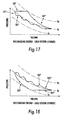
- Figure 2 shows an idealised P-V (pressure plotted against volume) diagram for energy store 10 in the discharging phase.
- the straight portion 180' represents isobaric cooling of the gas flow from, in this example, ambient temperature and pressure as it passes through second heat storage means 60; curve 170' at the left-hand side of the diagram represents an isentropic compression in the expander means 22; the straight portion 160' represents isobaric heating of the flow as it passes through the first heat storage means 50; and curve 150' at the right-hand side of the diagram represents an isentropic expansion of the gas in the compressor means 21.
- the recoverable work is equal to the shaded area inside the lines.
- the real P-V diagram is likely to exhibit some differences from the idealized cycle due to irreversible processes occurring within the real cycle.
- the low pressure part of the cycle can be either above or below atmospheric pressure, the gas does not have to be air and the low (T1) temperature can also be set above or below ambient temperature.
- Figure 3 shows an idealised P-V (pressure plotted against volume) diagram for energy store 10 in the charging phase.
- Curve 150 at the right-hand side of the diagram represents an isentropic compression of the gas flow in the compressor means 21 from, in this example, ambient temperature and pressure; the straight portion 160 represents isobaric cooling of the flow as it passes through the first heat storage means 50; curve 170 at the left-hand side of the diagram represents an isentropic expansion back to atmospheric pressure in the expander means 22; and the straight portion 180 represents isobaric heating of the flow as it passes through the second heat storage means 60 back to ambient temperature.
- the work done and hence the mechanical work stored is equal to the shaded area inside the lines.
- the real P-V diagram is again likely to exhibit some differences from the idealized cycle due to irreversible processes occurring within the real cycle.
- the low pressure part of the cycle can be either above or below atmospheric pressure, the gas does not have to be air and the low (T1) temperature can also be set above or below ambient temperature.
- Figure 4 shows an energy storage system 10' comprising: first compressor/expander means 20' including first compressor means 21' and first expander means 22'; second compressor/expander means 120 including second expander means 121 and second compressor means 122; power input means 40; power output means 140; first heat storage means 50'; second heat storage means 60'; high pressure transfer means 70',71',72 and 73; and low pressure transfer means 80',81',82 and 83.
- the first compressor means 21' comprises: low pressure inlet means 23'; a first compression chamber 24'; first compression piston means 25'; and high pressure exhaust means 26'.
- the first expander means 22' comprises: high pressure inlet means 27'; a first expansion chamber 28'; first expansion piston means 29'; and low pressure exhaust means 30'.
- the second expander means 121 comprises: low pressure outlet means 123; a second expansion chamber 124; second expansion piston means 125; and high pressure inlet means 126.
- the second compressor means 122 comprises: high pressure outlet means 127; a second compression chamber 128; second compression piston means 129; and low pressure inlet means 130.
- the power input means 40' comprises: a mechanical link from an energy source 41'; a driving mechanism 42' to the first compression piston means 25'; and a driving mechanism 43' to the first expansion piston means 29'.
- the power output means 140 comprises: a mechanical link from an energy demand 141; a driving mechanism 142 to the second expansion piston means 125; and a driving mechanism 143 to the second compression piston means 129.
- the first heat storage means 50' comprises a first insulated pressure vessel 51' suitable for the high pressure, high pressure inlet means 52',56, high pressure outlet means 54' and 55, hot distribution chamber 57, first ambient distribution chamber 58 and a first thermal store 53'.
- the second heat storage means 60' comprises a second insulated pressure vessel 61' suitable for the low pressure, low pressure inlet means 62',66, low pressure outlet means 64' and 65, cold distribution chamber 67, second ambient distribution chamber 68 and a second thermal store 63'.
- a low pressure gas in the low pressure transfer means 80' enters the first compressor means 21' via the low pressure inlet means 23' and is allowed to pass into the first compression chamber 24'. Once the gas has entered the first compression chamber 24', the low pressure inlet means 23' are sealed and the first compression piston means 25' is then actuated by driving mechanism 42'. Once the gas contained in the compression chamber 24' has been compressed by the compression piston means 25' up to approximately the level in the high pressure transfer means 70', the gas is transferred to the high pressure transfer means 70' by opening the high pressure exhaust means 26'.
- the gas is transferred by the high pressure transfer means 70' to the hot distribution chamber 57.
- the gas enters the hot distribution chamber 57 through the high pressure inlet means 52'.
- Gas leaves the hot distribution chamber 57 and passes through the first thermal store 53', which is enclosed within the first insulated pressure vessel 51'.
- As the gas passes through the first thermal store 53' it transfers thermal energy to the first thermal store 53' and enters the first ambient distribution chamber 58. It then leaves the first ambient distribution chamber 58 through the high pressure outlet means 54'.
- the gas now passes through the high pressure transfer means 71' and enters the first expander means 22' through the high pressure inlet means 27'.
- the high pressure gas entering the first expander means 22' via the high pressure inlet means 27' is allowed to pass into the first expansion chamber 28'. Once the gas has entered the first expansion chamber 28', the high pressure inlet means 27' are sealed and the first expansion piston means 29' is then actuated by driving mechanism 43'. Once the gas contained in the first expansion chamber 28' has been expanded by the first expansion piston means 29' down to approximately the level in the low pressure transfer means 81', the gas is transferred to the low pressure transfer means 81' by opening the low pressure exhaust means 30'.
- the gas is transferred by the low pressure transfer means 81' to the second heat storage means 60'.
- the gas enters the cold distribution chamber 67 through the low pressure inlet means 62' and passes through the second thermal store 63', which is enclosed within the second insulated pressure vessel 61'.
- As the gas passers through the second thermal store 63' it receives thermal energy from the second thermal store 63' and then enters the second ambient distribution chamber 68.
- the gas leaves the second ambient distribution chamber 68 through the low pressure outlet means 64'.
- the gas now passes through the low pressure transfer means 80' and is available to enter the first expander means 21' through the low pressure inlet means 23'.
- vent 90' allows ambient air to enter and leave the system as necessary and prevents a rise in entropy of the system. If the gas is not air and /or the low pressure is not atmospheric pressure then the vent 91' will lead to a reservoir of the gas 92' that may be kept at a stable temperature by means of a heat exchanger 93'. If no heat exchanger is used and/or the gas is not vented to atmosphere then there will be a steady rise in the entropy (and hence temperature) of the system.
- the power input is being used to directly drive the power output without any significant flows through the first and second heat storage means 50' and 60'.
- a low pressure gas in the low pressure transfer means 80' enters the first compressor means 21' via the low pressure inlet means 23' and is allowed to pass into the first compression chamber 24'. Once the gas has entered the first compression chamber 24', the low pressure inlet means 23' are sealed and the first compression piston means 25' is then actuated by driving mechanism 42'. Once the gas contained in the compression chamber 24' has been compressed by the compression piston means 25' up to approximately the level in the high pressure transfer means 70', the gas is transferred to the high pressure transfer means 70' by opening the high pressure exhaust means 26'.
- the gas is transferred by the high pressure transfer means 70' to the hot distribution chamber 57.
- the gas enters the hot distribution chamber 57 through the high pressure inlet means 52'.
- the gas leaves the hot distribution chamber 57 and passes through the high pressure outlet 55 into the high pressure transfer means 72.
- the gas now passes through the high pressure transfer means 72 and enters the second expander means 121 through the high pressure inlet means 126.
- the high pressure gas entering the second expander means 121 via the high pressure inlet means 126 is allowed to pass into the second expansion chamber 124. Once the gas has entered the second expansion chamber 124, the high pressure inlet means 126 are sealed and the second expansion piston means 125 is then actuated by driving mechanism 142. Once the gas contained in the second expansion chamber 124 has been expanded by the second expansion piston means 125 down to approximately the level in the low pressure transfer means 82, the gas is transferred to the low pressure transfer means 82 by opening the low pressure exhaust means 123.
- the gas is transferred by the low pressure transfer means 82 to the second heat storage means 60'.
- the gas enters the second ambient distribution chamber 68 through the low pressure inlet means 66 and leaves immediately through the low pressure outlet 64'.
- the gas now passes through the low pressure transfer means 80' and is available to enter the first compressor means 21' through the low pressure inlet means 23'.
- a cold low pressure gas in the low pressure transfer means 83 enters the second compressor means 122 via the low pressure inlet means 130 and is allowed to pass into the second compression chamber 128.
- the inlet means 130 are sealed and the second compression piston means 25 is then actuated by driving mechanism 143.
- the gas contained in the second compression chamber 128 has been compressed by the second compression piston means 129 up to approximately the level in the high pressure transfer means 73, the gas is transferred to the high pressure transfer means 73 by opening the high pressure exhaust means 127.
- the temperature of the gas entering the high pressure exhaust means 73 should be approximately ambient.
- the gas is transferred by the high pressure transfer means 73 to the first ambient distribution chamber 58.
- the gas enters the first ambient distribution chamber 58 through the high pressure inlet means 56 and leaves immediately through the high pressure outlet 54'.
- the gas now passes through the high pressure transfer means 71' and is available to enter the first expander means 22' through the high pressure inlet means 27'.
- the high pressure gas entering the first expander means 22' via the high pressure inlet means 27' is allowed to pass into the first expansion chamber 28'. Once the gas has entered the first expansion chamber 28', the high pressure inlet means 27' are sealed and the first expansion piston means 29' is then actuated by driving mechanism 43'. Once the gas contained in the first expansion chamber 28' has been expanded by the first expansion piston means 29' down to approximately the level in the low pressure transfer means 81', the gas is transferred to the low pressure transfer means 81' by opening the low pressure exhaust means 30'.
- the gas is transferred by the low pressure transfer means 81' to the second heat storage means 60'.
- the gas enters the cold distribution chamber 67 through the low pressure inlet means 62' and leaves immediately through the low pressure outlet 65.
- the gas now passes through the low pressure transfer means 83 and is available to enter the second compressor means 122 through the low pressure inlet means 130.
- the power input equals the power output then there should be minimal flows through the first and second heat storage means 50' and 60' and there is, in effect, a direct fluid path between the first compressor means 21' and the second expander means 121 and also the first expander means 22' and the second compressor means 122. Any losses in this 'fluidic transmission' are likely to materialise as waste heat and it may be necessary to cool the high pressure transfer means 71' with a heat exchanger means 94 in order to maintain the base temperature at the correct level. This is in addition to that provided for on the low pressure transfer means 80' covered below.
- vent 90' allows ambient air to enter and leave the system as necessary and prevents a rise in entropy of the system. If the gas is not air and /or the low pressure is not atmospheric pressure then the vent 91' will lead to a reservoir of the gas 92' that may be kept at a stable temperature by means of a heat exchanger 93'. If no heat exchanger is used and/or the gas is not vented to atmosphere then there will be a steady rise in the entropy (and hence temperature) of the system.
- a high pressure gas in the high pressure transfer means 72 enters the second expander means 121 via the high pressure inlet means 126 and is allowed to pass into the second expansion chamber 124. Once the gas has entered the second expansion chamber 124, the high pressure inlet means 126 are sealed and the second expansion piston means 125 is then actuated by driving mechanism 142. Once the gas contained in the second expansion chamber 124 has been expanded by the expansion piston means 125 down to approximately the level in the low pressure transfer means 82, the gas is transferred to the low pressure transfer means 82 by opening the high pressure exhaust means 123.
- the gas is transferred by the low pressure transfer means 82 to the second heat storage means 60'.
- the gas enters the second ambient distribution chamber 68 through the high pressure inlet means 66 and passes through the second thermal store 63', which is enclosed within the second insulated pressure vessel 61'.
- the gas now passes through the low pressure transfer means 83 and enters the second compressor means 122 through the low pressure inlet means 130.
- the low pressure gas entering the second compressor means 122 via the low pressure inlet means 130 is allowed to pass into the second compression chamber 128. Once the gas has entered the second compression chamber 128, the low pressure inlet means 130 are sealed and the second compression piston means 129 is then actuated by driving mechanism 143. Once the gas contained in the second compression chamber 128 has been compressed by the second compression piston means 129 up to approximately the level in the high pressure transfer means 73, the gas is transferred to the high pressure transfer means 73 by opening the high pressure exhaust means 127.
- the gas is transferred by the high pressure transfer means 73 to the first heat storage means 50'.
- the gas enters the first ambient distribution chamber 58 through the high pressure inlet means 56 and passes through the first thermal store 53', which in enclosed within the first insulated pressure vessel 51'.
- the gas passes through the first thermal store 53' it receives thermal energy from the first thermal store 53' and leaves the hot distribution means 57 through the high pressure outlet means 55.
- the gas now passes through the high pressure transfer means 72 and is available to enter the second expander means 121 through the high pressure inlet means 126.
- vent 90' allows ambient air to enter and leave the system as necessary and prevents a rise in entropy of the system. If the gas is not air and /or the low pressure is not atmospheric pressure then the vent 91' will lead to a reservoir of the gas 92' that may be kept at a stable temperature by means of a heat exchanger 93'. If no heat exchanger is used and/or the gas is not vented to atmosphere then there will be a steady rise in the entropy (and hence temperature) of the system.
Landscapes
- Engineering & Computer Science (AREA)
- Chemical & Material Sciences (AREA)
- Combustion & Propulsion (AREA)
- Mechanical Engineering (AREA)
- General Engineering & Computer Science (AREA)
- Filling Or Discharging Of Gas Storage Vessels (AREA)
- Engine Equipment That Uses Special Cycles (AREA)
- Compressors, Vaccum Pumps And Other Relevant Systems (AREA)
Description
- The present invention relates generally to apparatus for energy storage.
- Current energy storage techniques are either expensive, have poor charge/discharge efficiencies or have unwanted environmental consequences due to the types of chemicals involved or type of land use.
- The storage techniques that are currently available that use no chemicals are: pumped hydro storage; flywheel storage; and compressed air energy storage (CAES). These techniques all have certain advantages and disadvantages:
- Pumped hydro - require a certain geological set-up and has limited storage capacity. To increase storage requires a large area of land per unit of power stored.
- Flywheels - good charge/discharge efficiency, but limited power storage per unit mass and expensive.
- Compressed Air Energy Storage - the main drawback of CAES is its reliance on geological structures: the lack of suitable underground caverns substantially limits the usability of this storage method. However, for locations where it is suitable, it can provide a viable option for storing large quantities of energy for long periods. To store compressed air in man-made pressure vessels is problematic since large wall thicknesses are typically required. This means there are no economies of scale using manufactured pressured vessels. In addition, charge/discharge efficiency is not high.
-
WO 2008/148962 discloses an other energy storage technique using two heat storage means placed in 2 a cycle to produce a hot and a cold store. Accordingly, there is a desire to provide an improved way of storing energy which overcomes, or at least alleviates some of the problems associated with the prior art. In particular, there is a desire to provide a cheap, efficient, relatively compact and environmentally inert alternative to current techniques. - In accordance with a first aspect of the present invention, there is provided apparatus for storing energy as set forth in
claim 1 below. - In this way, energy storage apparatus is provided in which first and second heat storage means are placed within a thermal heat pump cycle to produce a hot and cold store respectively during charging. Energy is then recoverable in a discharging mode by passing gas through the cooled second heat storage means, compressing gas cooled by the second heat storage means, heating the cooled compressed gas by exposing the gas to the heated first heat storage means, and allowing the heated gas to expand by doing work on generator means.
- The gas may be air from the surrounding atmosphere. Advantageously, the use of atmospheric air as the working fluid means that there is no need to use potentially polluting coolants. Alternatively, the gas may be nitrogen or a noble gas (e.g. Argon or Helium).
- The system base pressure (e.g. the pressure in the second heat storage means) can be varied from sub-atmospheric to above atmospheric. If the system base pressure is raised above atmospheric, then the peak pressure will be increased for a set temperature range and the compression and expansion piston means will become more compact. There is a trade off as the storage vessels will become more expensive in order to deal with the higher pressures. Conversely if the system pressure is sub-atmospheric, then the peak pressures will be lower and the storage vessels will become less expensive against the compression and expansion piston means increasing in size.
- The compression may be substantially isentropic or adiabatic. The heat transfer from gas to the first heat storage means may be substantially isobaric. The expansion may be substantially isentropic or adiabatic. The heat transfer from the second heat storage means to the gas may be substantially isobaric. In reality it is not possible to achieve perfect isentropic processes, as irreversibility in the process and heat transfer during the process will occur. Therefore it should be noted that where a process is referred to as isentropic, it should be understood as meaning near or substantially isentropic.
- Advantageously, the use of a reciprocating piston compressor/expander can offer significantly improved efficiency over conventional aerodynamic rotary compressors/expanders.
- At least one of the first and second heat storage means may comprise a chamber for receiving gas, and particulate material (e.g. a bed of particulate material) housed in the chamber. The particulate material may comprise solid particles and/or fibres packed (e.g. randomly) to form a gas-permeable structure. The solid particles and/or fibres may have a low thermal inertia. For example, the solid particles and/or fibres may be metallic. In another embodiment, the solid particles and/or fibres may comprise a mineral or ceramic. For example, the solid particles may comprise gravel.
- The apparatus may further comprise generator means for recovering energy stored in the first and second heat storage means. The generator means may be coupled to one or both of the compression piston means and the expansion piston means. One or both of the compression piston means and the expansion piston means may be configurable to operate in reverse during discharge (e.g. when discharging, the expansion piston means may be configurable to compress cooled gas and the compression piston means may be configurable to allow heated gas to expand).
- There is further provided a method as set forth in claim 17 below.
- In accordance with a second aspect of the present invention, there is provided apparatus for transmitting mechanical power from an input device to an output device as set forth in claim 12 below.
- In this way, a thermodynamic transmission system is provided in which energy may be stored in a "buffer" in a first mode of operation when the power output from the system is less than the power supplied and is automatically recovered in a second mode of operation when the power required from the system increases above that of the power supplied. The change between the first and second modes of operation may occur automatically. For example, the apparatus may be configured to react automatically to an imbalance in input and output powers. When the power supplied and used are balanced, the system automatically bypasses the first and second heat storage means.
- The gas may be air from the surrounding atmosphere.
- The compression provided by the first and second compression piston means may be substantially isentropic or adiabatic. The heat transfer from gas to the first heat storage means may be substantially isobaric. The expansion provided by the first and second expansion piston means may be substantially isentropic or adiabatic. The heat transfer from the second heat storage means to the gas may be substantially isobaric.
- At least one of the first and second heat storage means may comprise a chamber for receiving gas, and particulate material (e.g. a bed of particulate material) housed in the chamber. The particulate material may comprise solid particles and/or fibres packed (e.g. randomly) to form a gas-permeable structure. The solid particles and/or fibres may have a low thermal inertia. For example, the solid particles and/or fibres may be metallic. In another embodiment, the solid particles and/or fibres may comprise a mineral or ceramic. For example, the solid particles may comprise gravel.
- Embodiments of the present invention will now be described by way of example with reference to the accompanying drawings in which:
-
Figure 1 is a schematic illustration of energy storage apparatus according to the first aspect of the present invention; -
Figure 2 shows a P-v diagram modelling a typical cycle of the apparatus ofFigure 1 during discharging; -
Figure 3 shows a P-V diagram modelling a typical cycle of the apparatus ofFigure 1 during charging; and -
Figure 4 is a schematic illustration of transmission apparatus incorporating energy storing apparatus according to the second aspect of the present invention. -
Figure 1 shows an arrangement in which thermal storage means are inserted within a thermal heatpump/engine cycle. The cycle used has two different stages that can be split into separate devices or combined into one device. -
Figure 1 shows a device for the combined cycle which employs substantially isentropic compression, using a compressor, in this case a reciprocating device, which raises the temperature and pressure of the working fluid (e.g. air). The working fluid then passes through a particulate thermal storage medium (potentially gravel or metallic granules) where it is cooled. It is then expanded to cool it and lower the pressure before it passes through another particulate store, where it is warmed back to ambient and then back to step one. - To discharge working fluid passes through the second heat storage to 2, is compressed to 3, warms via the first heat storage to 4, expands back to 1.
- This device automatically has the advantage of avoiding the need for any isothermal compression or expansion. This means that the inevitable losses associated with the charge/discharge of the hot only or cold only devices can be avoided. It is inherently more efficient.
-

Cool from 2 to 3:
Where:


Expand from 3 to 4:
where
Warm from 4 to 1:
Mass of fluid involved per cycle:
M= pV/RT (equation of state)
Thermal energy stored:


- As this cycle is theoretically reversible high efficiencies should be achievable.
- In
Figure 4 , apparatus is shown linking two thermodynamic machines with an energy store, such that the energy input is completely independent of action from the output. This transforms the device into a form of thermodynamic transmission with the ability to store a significant amount of energy. - In the embodiment illustrated, all plumbing must be highly insulated with the exception of the Ta pipes which should be exposed to maintain the datum.
- This set up automatically bypasses the storage mass if power supplied equals the power removed, any imbalance gives seamless and automatic transfer of energy to and from the buffer.
- The key principle is that energy addition or removal is solely a function of the relative rates of gas flow through the input and output devices, If these are equal then no energy enters of leaves the store, if the input flow is greater then energy is stored, if the output flow is greater, energy leaves the store.
- To avoid an overall rise in system entropy at least one ambient flow must be cooled. This could be achieved by opening the Ta (ambient) end of the second heat storage to the atmosphere such that the cold side is then at ambient pressure. If the entire device is worked at elevated pressure it may be made more compact, this may have application in transport for hybrid vehicles and the like.
- For bulk storage of energy it will be desirable to store at ambient pressure, this may be achieved by passing the pressurised flows from the machinery through heat exchangers at the ends of the storage masses and blowing ambient pressure air through the stores via these heat exchangers.
- Where a heat exchanger and unpressurised store is used it is likely that there will be a temperature drop associated with each transfer stage. For example the air might leave the hot compressor at 500 deg C. This air will be run through the heat exchanger and might enter the unpressurised hot store at about 450 deg C. When the system is reversed the air temperature will only be heated to approximately 400 deg C. In this situation it can be beneficial to supplement the heat in the unpressurised store with some external heat source, such as electricity or gas.
- Because this heat is added at a high temperature there is a significant benefit in terms of increasing the energy density of the store and the recoverable energy upon discharge. For example in the example given the store might be heated to 550 deg C and the return flow of air during the discharge cycle would be reheated to its original temperature of 500 deg C.
- In addition this heating can be used to maintain the temperature of the store if it is left undischarged for long periods of time. This has particular application in UPS or standby power duties
- Pressurised bulk storage may be achieved by placing the storage volumes underground at significant depth, for example old mines could be used. The mass of the earth above may then be used to balance the high gas pressures within the store.
- Additional Cycles where it can be inserted in the thermal heat-pump/engine cycle.
-
Figure 1 shows anenergy storage system 10 comprising: compressor/expander means 20 including compressor means 21, expander means 22, and power input/output means 40; first heat storage means 50, second heat storage means 60, high pressure transfer means 70,71 and low pressure transfer means 80,81. In this diagram the compressor/expander means 20 is shown as a single unit. - The compressor means 21 comprises: low pressure inlet means 23; a
compression chamber 24; compression piston means 25; and high pressure exhaust means 26. In this example, the compressor means 21 is configured to run in reverse and operate as an expander means in the discharging phase of the cycle. There are two other alternative ways of achieving expansion in the discharging phase: (1) switching the flows when the system is reversed so that the compressor means 21 is only used for compressing gas and the expander means 22 for expanding gas, but this has the disadvantage of incorrect cylinder sizing; and (2) providing a separate compressor/expander for the discharge part of the cycle with suitable switching of the flow. - The expander means 22 comprises: high pressure inlet means 27; an
expansion chamber 28; expansion piston means 29; and low pressure exhaust means 30. In this example, the expander means 22 is configured to run in reverse and operate as a compressor means in the discharging phase of the cycle. There are two other ways of achieving expansion in the discharging phase: (1) switching the flows when the system is reversed so that the compressor means 21 is only used for compressing gas and the expander means 22 for expanding gas, but this has the disadvantage of incorrect cylinder sizing; and (2) providing a separate compressor/expander for the discharge part of the cycle with suitable switching of the flow. - The power input/output means 40 comprises a mechanical link from an energy source/
demand 41, a driving mechanism to thecompressor 42, and a driving mechanism to theexpander 43. The energy source/demand 41 is an energy source when used in power input mode or an energy demand when used in power output mode. - The first heat storage means 50 comprises a first
insulated pressure vessel 51 suitable for the high pressure, a high pressure inlet/outlet 52, a firstthermal store 53 and a high pressure inlet/outlet 54. - The second heat storage means 60 comprises a second
insulated pressure vessel 61 suitable for the low pressure, a low pressure inlet/outlet 62, a secondthermal store 63 and a low pressure inlet/outlet 64. - To charge the
system 10, a low pressure gas in the low pressure transfer means 80 enters the compressor means 21 via the low pressure inlet means 23 and is allowed to pass into thecompression chamber 24. Once the gas has entered thecompression chamber 24, the low pressure inlet means 23 are sealed and the compression piston means 25 is then actuated by drivingmechanism 42. Once the gas contained in thecompression chamber 24 has been compressed by the compression piston means 25 up to approximately the level in the high pressure transfer means 70, the gas is transferred to the high pressure transfer means 70 by opening the high pressure exhaust means 26. - The gas is transferred by the high pressure transfer means 70 to the first heat storage means 50. The gas enters the first heat storage means 50 through the high pressure inlet/outlet means 52 and passes through the first
thermal store 53, which is enclosed within the firstinsulated pressure vessel 51. As the gas passes through the firstthermal store 53 it transfers thermal energy to the firstthermal store 53 and leaves the first heat storage means 50 through the high pressure inlet/outlet means 54. The gas now passes through the high pressure transfer means 71 and enters the expander means 22 through the high pressure inlet means 27. - The high pressure gas entering the expander means 22 via the high pressure inlet means 27 is allowed to pass into the
expansion chamber 28. Once the gas has entered theexpansion chamber 28, the high pressure inlet means 27 are sealed and the expansion piston means 29 is then actuated by drivingmechanism 43. Once the gas contained in theexpansion chamber 28 has been expanded by the expansion piston means 29 down to approximately the level in the low pressure transfer means 81, the gas is transferred to the low pressure transfer means 81 by opening the low pressure exhaust means 30. - The gas is transferred by the low pressure transfer means 81 to the second heat storage means 60. The gas enters the second heat storage means 60 through the low pressure inlet/outlet means 62 and passes through the second
thermal store 63, which is enclosed within the secondinsulated pressure vessel 61. As the gas passes through the secondthermal store 63 it receives thermal energy from the secondthermal store 63 and leaves the second heat storage means 60 through the low pressure inlet/outlet means 64. The gas now passes through the low pressure transfer means 80 and is available to enters the compressor means 21 through the low pressure inlet means 23. - This process can be run until the first and second heat storage means 50,60 are fully charged, after which no more energy can be stored in the system. To discharge the system, the process is reversed and the compressor means 21 operates as an expander and the expander means 22 operates as a compressor. The flows through the system are reversed and once the system has discharged, the temperatures throughout the system will be approximately returned to that at which they started.
- If the gas is air and the low pressure is set at atmospheric pressure then it is likely that there will be a
vent vent 90 allows ambient air to enter and leave the system as necessary and prevents a rise in entropy of the system. If the gas is not air and/or the low pressure is not atmospheric pressure then thevent 91 will lead to a reservoir of thegas 92 that may be kept at a stable temperature by means of aheat exchanger 93. If no heat exchanger is used and/or the gas is not vented to atmosphere then there will be a steady rise in the entropy (and hence temperature) of the system. -
Figure 2 shows an idealised P-V (pressure plotted against volume) diagram forenergy store 10 in the discharging phase. The straight portion 180' represents isobaric cooling of the gas flow from, in this example, ambient temperature and pressure as it passes through second heat storage means 60; curve 170' at the left-hand side of the diagram represents an isentropic compression in the expander means 22; the straight portion 160' represents isobaric heating of the flow as it passes through the first heat storage means 50; and curve 150' at the right-hand side of the diagram represents an isentropic expansion of the gas in the compressor means 21. The recoverable work is equal to the shaded area inside the lines. Of course, the real P-V diagram is likely to exhibit some differences from the idealized cycle due to irreversible processes occurring within the real cycle. In addition, as has already been mentioned, the low pressure part of the cycle can be either above or below atmospheric pressure, the gas does not have to be air and the low (T1) temperature can also be set above or below ambient temperature. -
Figure 3 shows an idealised P-V (pressure plotted against volume) diagram forenergy store 10 in the charging phase.Curve 150 at the right-hand side of the diagram represents an isentropic compression of the gas flow in the compressor means 21 from, in this example, ambient temperature and pressure; thestraight portion 160 represents isobaric cooling of the flow as it passes through the first heat storage means 50;curve 170 at the left-hand side of the diagram represents an isentropic expansion back to atmospheric pressure in the expander means 22; and thestraight portion 180 represents isobaric heating of the flow as it passes through the second heat storage means 60 back to ambient temperature. The work done and hence the mechanical work stored is equal to the shaded area inside the lines. Of course, the real P-V diagram is again likely to exhibit some differences from the idealized cycle due to irreversible processes occurring within the real cycle. In addition, as has already been mentioned, the low pressure part of the cycle can be either above or below atmospheric pressure, the gas does not have to be air and the low (T1) temperature can also be set above or below ambient temperature. -
Figure 4 shows an energy storage system 10' comprising: first compressor/expander means 20' including first compressor means 21' and first expander means 22'; second compressor/expander means 120 including second expander means 121 and second compressor means 122; power input means 40; power output means 140; first heat storage means 50'; second heat storage means 60'; high pressure transfer means 70',71',72 and 73; and low pressure transfer means 80',81',82 and 83. - The first compressor means 21' comprises: low pressure inlet means 23'; a
first compression chamber 24'; first compression piston means 25'; and high pressure exhaust means 26'. - The first expander means 22' comprises: high pressure inlet means 27'; a first expansion chamber 28'; first expansion piston means 29'; and low pressure exhaust means 30'.
- The second expander means 121 comprises: low pressure outlet means 123; a
second expansion chamber 124; second expansion piston means 125; and high pressure inlet means 126. - The second compressor means 122 comprises: high pressure outlet means 127; a
second compression chamber 128; second compression piston means 129; and low pressure inlet means 130. - The power input means 40' comprises: a mechanical link from an energy source 41'; a driving mechanism 42' to the first compression piston means 25'; and a driving mechanism 43' to the first expansion piston means 29'.
- The power output means 140 comprises: a mechanical link from an
energy demand 141; a driving mechanism 142 to the second expansion piston means 125; and adriving mechanism 143 to the second compression piston means 129. - The first heat storage means 50' comprises a first insulated pressure vessel 51' suitable for the high pressure, high pressure inlet means 52',56, high pressure outlet means 54' and 55,
hot distribution chamber 57, firstambient distribution chamber 58 and a first thermal store 53'. - The second heat storage means 60' comprises a second insulated pressure vessel 61' suitable for the low pressure, low pressure inlet means 62',66, low pressure outlet means 64' and 65,
cold distribution chamber 67, secondambient distribution chamber 68 and a second thermal store 63'. - Assuming there is sufficient energy stored in the first and second heat storage means 50' and 60', then there are only five possible modes of operation:
- 1. Charging Only. If no energy is being extracted by the power output means 140 and energy is being added by the power input means 40' then the flow will charge the first and second heat storage means 50' and 60'.
- 2. Part Charging and Part Direct Flow. If less energy is being extracted by the power output means 140 than is being supplied by the power input means 40' then the flow will split with enough of the flow going to supply the power output requirements of the compressor/expander means 120 and the remaining flow will charge the first and second heat storage means 50' and 60'. This can be analysed as a combination of (1) and (3).
- 3. Direct Flow. If the same energy is being extracted by the power output means 140 as is being supplied by the power input means 40' then almost all of the flow will bypass the first and second heat storage means 50' and 60' and pass directly from the compressor means 21' to the expander means 121 and also the expander means 22' to the compressor means 122.
- 4. Part Direct Flow and Part Discharging. If more energy is being extracted by the power output means 140 than is being supplied by the power input means 40' then the flow from the compressor/expander means 20' will pass directly through the system as for case (3) and there will be an additional flow which will be drawn from the first and second heat storage means 50' and 60'. This additional flow should combine with the direct flow to equal the power output required. This can be analysed as a combination of (3) and (5).
- 5. Discharging only. If no power is being supplied by the power input means 40' then all of power to drive the compressor/expander means 120 must be drawn from the first and second heat storage means 50' and 60'.
- In this scenario the power input is being used purely to charge the first and second heat storage means 50' and 60'. It is identical to the situation of charging the device shown in
Figure 1 . In this configuration the power is being input only and there is therefore no need to consider any flow through the second compressor means 121 and second expander means 122. - In use, a low pressure gas in the low pressure transfer means 80' enters the first compressor means 21' via the low pressure inlet means 23' and is allowed to pass into the
first compression chamber 24'. Once the gas has entered thefirst compression chamber 24', the low pressure inlet means 23' are sealed and the first compression piston means 25' is then actuated by driving mechanism 42'. Once the gas contained in thecompression chamber 24' has been compressed by the compression piston means 25' up to approximately the level in the high pressure transfer means 70', the gas is transferred to the high pressure transfer means 70' by opening the high pressure exhaust means 26'. - The gas is transferred by the high pressure transfer means 70' to the
hot distribution chamber 57. The gas enters thehot distribution chamber 57 through the high pressure inlet means 52'. Gas leaves thehot distribution chamber 57 and passes through the first thermal store 53', which is enclosed within the first insulated pressure vessel 51'. As the gas passes through the first thermal store 53' it transfers thermal energy to the first thermal store 53' and enters the firstambient distribution chamber 58. It then leaves the firstambient distribution chamber 58 through the high pressure outlet means 54'. The gas now passes through the high pressure transfer means 71' and enters the first expander means 22' through the high pressure inlet means 27'. - The high pressure gas entering the first expander means 22' via the high pressure inlet means 27' is allowed to pass into the first expansion chamber 28'. Once the gas has entered the first expansion chamber 28', the high pressure inlet means 27' are sealed and the first expansion piston means 29' is then actuated by driving mechanism 43'. Once the gas contained in the first expansion chamber 28' has been expanded by the first expansion piston means 29' down to approximately the level in the low pressure transfer means 81', the gas is transferred to the low pressure transfer means 81' by opening the low pressure exhaust means 30'.
- The gas is transferred by the low pressure transfer means 81' to the second heat storage means 60'. The gas enters the
cold distribution chamber 67 through the low pressure inlet means 62' and passes through the second thermal store 63', which is enclosed within the second insulated pressure vessel 61'. As the gas passers through the second thermal store 63' it receives thermal energy from the second thermal store 63' and then enters the secondambient distribution chamber 68. The gas leaves the secondambient distribution chamber 68 through the low pressure outlet means 64'. The gas now passes through the low pressure transfer means 80' and is available to enter the first expander means 21' through the low pressure inlet means 23'. - If the gas is air and the low pressure is set at atmospheric pressure then it is likely that there will be a vent 90' or 91' located within the low pressure transfer means 80'. The vent 90' allows ambient air to enter and leave the system as necessary and prevents a rise in entropy of the system. If the gas is not air and /or the low pressure is not atmospheric pressure then the vent 91' will lead to a reservoir of the gas 92' that may be kept at a stable temperature by means of a
heat exchanger 93'. If no heat exchanger is used and/or the gas is not vented to atmosphere then there will be a steady rise in the entropy (and hence temperature) of the system. - In this scenario the power input is being used to directly drive the power output without any significant flows through the first and second heat storage means 50' and 60'.
- In use, a low pressure gas in the low pressure transfer means 80' enters the first compressor means 21' via the low pressure inlet means 23' and is allowed to pass into the
first compression chamber 24'. Once the gas has entered thefirst compression chamber 24', the low pressure inlet means 23' are sealed and the first compression piston means 25' is then actuated by driving mechanism 42'. Once the gas contained in thecompression chamber 24' has been compressed by the compression piston means 25' up to approximately the level in the high pressure transfer means 70', the gas is transferred to the high pressure transfer means 70' by opening the high pressure exhaust means 26'. - The gas is transferred by the high pressure transfer means 70' to the
hot distribution chamber 57. The gas enters thehot distribution chamber 57 through the high pressure inlet means 52'. The gas leaves thehot distribution chamber 57 and passes through thehigh pressure outlet 55 into the high pressure transfer means 72. The gas now passes through the high pressure transfer means 72 and enters the second expander means 121 through the high pressure inlet means 126. - The high pressure gas entering the second expander means 121 via the high pressure inlet means 126 is allowed to pass into the
second expansion chamber 124. Once the gas has entered thesecond expansion chamber 124, the high pressure inlet means 126 are sealed and the second expansion piston means 125 is then actuated by driving mechanism 142. Once the gas contained in thesecond expansion chamber 124 has been expanded by the second expansion piston means 125 down to approximately the level in the low pressure transfer means 82, the gas is transferred to the low pressure transfer means 82 by opening the low pressure exhaust means 123. - The gas is transferred by the low pressure transfer means 82 to the second heat storage means 60'. The gas enters the second
ambient distribution chamber 68 through the low pressure inlet means 66 and leaves immediately through the low pressure outlet 64'. The gas now passes through the low pressure transfer means 80' and is available to enter the first compressor means 21' through the low pressure inlet means 23'. - In addition, a cold low pressure gas in the low pressure transfer means 83 enters the second compressor means 122 via the low pressure inlet means 130 and is allowed to pass into the
second compression chamber 128. Once the gas has entered thesecond compression chamber 128, the inlet means 130 are sealed and the second compression piston means 25 is then actuated by drivingmechanism 143. Once the gas contained in thesecond compression chamber 128 has been compressed by the second compression piston means 129 up to approximately the level in the high pressure transfer means 73, the gas is transferred to the high pressure transfer means 73 by opening the high pressure exhaust means 127. The temperature of the gas entering the high pressure exhaust means 73 should be approximately ambient. - The gas is transferred by the high pressure transfer means 73 to the first
ambient distribution chamber 58. The gas enters the firstambient distribution chamber 58 through the high pressure inlet means 56 and leaves immediately through the high pressure outlet 54'. The gas now passes through the high pressure transfer means 71' and is available to enter the first expander means 22' through the high pressure inlet means 27'. - The high pressure gas entering the first expander means 22' via the high pressure inlet means 27' is allowed to pass into the first expansion chamber 28'. Once the gas has entered the first expansion chamber 28', the high pressure inlet means 27' are sealed and the first expansion piston means 29' is then actuated by driving mechanism 43'. Once the gas contained in the first expansion chamber 28' has been expanded by the first expansion piston means 29' down to approximately the level in the low pressure transfer means 81', the gas is transferred to the low pressure transfer means 81' by opening the low pressure exhaust means 30'.
- The gas is transferred by the low pressure transfer means 81' to the second heat storage means 60'. The gas enters the
cold distribution chamber 67 through the low pressure inlet means 62' and leaves immediately through thelow pressure outlet 65. The gas now passes through the low pressure transfer means 83 and is available to enter the second compressor means 122 through the low pressure inlet means 130. - If the power input equals the power output then there should be minimal flows through the first and second heat storage means 50' and 60' and there is, in effect, a direct fluid path between the first compressor means 21' and the second expander means 121 and also the first expander means 22' and the second compressor means 122. Any losses in this 'fluidic transmission' are likely to materialise as waste heat and it may be necessary to cool the high pressure transfer means 71' with a heat exchanger means 94 in order to maintain the base temperature at the correct level. This is in addition to that provided for on the low pressure transfer means 80' covered below.
- If the gas is air and the low pressure is set at atmospheric pressure then it is likely that there will be a vent 90' or 91' located within the low pressure transfer means 80'. The vent 90' allows ambient air to enter and leave the system as necessary and prevents a rise in entropy of the system. If the gas is not air and /or the low pressure is not atmospheric pressure then the vent 91' will lead to a reservoir of the gas 92' that may be kept at a stable temperature by means of a
heat exchanger 93'. If no heat exchanger is used and/or the gas is not vented to atmosphere then there will be a steady rise in the entropy (and hence temperature) of the system. - In this scenario the power is all being drawn from the first and second heat storage means 50' and 60'. It is identical to the situation of discharging for the device in
Figure 1 . However, in this configuration the power is being output only and there is therefore no need to consider any flows through the first compressor means 21' and first expander means 22'. Assuming that there is sufficient stored energy to supply this power then it can be analysed as follows. - In use, a high pressure gas in the high pressure transfer means 72 enters the second expander means 121 via the high pressure inlet means 126 and is allowed to pass into the
second expansion chamber 124. Once the gas has entered thesecond expansion chamber 124, the high pressure inlet means 126 are sealed and the second expansion piston means 125 is then actuated by driving mechanism 142. Once the gas contained in thesecond expansion chamber 124 has been expanded by the expansion piston means 125 down to approximately the level in the low pressure transfer means 82, the gas is transferred to the low pressure transfer means 82 by opening the high pressure exhaust means 123. - The gas is transferred by the low pressure transfer means 82 to the second heat storage means 60'. The gas enters the second
ambient distribution chamber 68 through the high pressure inlet means 66 and passes through the second thermal store 63', which is enclosed within the second insulated pressure vessel 61'. As the gas passes through the second thermal store 63' it transfers thermal energy to the second thermal store 63' and leaves thecold distribution chamber 67 through the low pressure outlet means 65. The gas now passes through the low pressure transfer means 83 and enters the second compressor means 122 through the low pressure inlet means 130. - The low pressure gas entering the second compressor means 122 via the low pressure inlet means 130 is allowed to pass into the
second compression chamber 128. Once the gas has entered thesecond compression chamber 128, the low pressure inlet means 130 are sealed and the second compression piston means 129 is then actuated by drivingmechanism 143. Once the gas contained in thesecond compression chamber 128 has been compressed by the second compression piston means 129 up to approximately the level in the high pressure transfer means 73, the gas is transferred to the high pressure transfer means 73 by opening the high pressure exhaust means 127. - The gas is transferred by the high pressure transfer means 73 to the first heat storage means 50'. The gas enters the first
ambient distribution chamber 58 through the high pressure inlet means 56 and passes through the first thermal store 53', which in enclosed within the first insulated pressure vessel 51'. As the gas passes through the first thermal store 53' it receives thermal energy from the first thermal store 53' and leaves the hot distribution means 57 through the high pressure outlet means 55. The gas now passes through the high pressure transfer means 72 and is available to enter the second expander means 121 through the high pressure inlet means 126. - If the gas is air and the low pressure is set at atmospheric pressure then it is likely that there will be a vent 90' or 91' located within the low pressure transfer means 80'. The vent 90' allows ambient air to enter and leave the system as necessary and prevents a rise in entropy of the system. If the gas is not air and /or the low pressure is not atmospheric pressure then the vent 91' will lead to a reservoir of the gas 92' that may be kept at a stable temperature by means of a
heat exchanger 93'. If no heat exchanger is used and/or the gas is not vented to atmosphere then there will be a steady rise in the entropy (and hence temperature) of the system.
Claims (21)
- Apparatus (10) for storing energy, comprising:compression chamber means (24) for receiving a gas;compression piston means (21) for compressing gas contained in the compression chamber means (24);first heat storage means (50) for receiving and storing thermal energy from gas compressed by the compression piston means (21);expansion chamber means (28) for receiving gas after exposure to the first heat storage means (50);expansion piston means (22) for expanding gas received in the expansion chamber means (28); and,second heat storage means (60) for transferring thermal energy to gas expanded by the expansion piston means (22),wherein the apparatus is configured such that the gas passes through each of the first and second heat storage means for transfer of thermal energy from or to the gas.
- Apparatus (10) according to claim 1, wherein the gas is atmospheric air, nitrogen or a noble gas.
- Apparatus (10) according to claim 1 or claim 2, wherein the apparatus is configured such that the gas re-enters the compression chamber after passing through the second heat storage means.
- Apparatus (10) according to claim 1 or claim 2, wherein the apparatus has a base system pressure above atmospheric pressure.
- Apparatus (10) according to any of the preceding claims, wherein at least one of the first and second heat storage means comprises a chamber for receiving gas, and particulate material housed in the chamber.
- Apparatus (10) according to claim 5, wherein the particulate material comprises solid particles and/or fibres packed to form a gas-permeable structure.
- Apparatus (10) according to claim 6, wherein the solid particles and/or fibres are metallic.
- Apparatus (10) according to claim 6, wherein the solid particles comprise a mineral or ceramic.
- Apparatus (10) according to any of the preceding claims, further comprising generator means for recovering energy stored in the first and second heat storage means.
- Apparatus (10) according to claim 9, wherein the generator means is coupled to one or both of the compression piston means and the expansion piston means.
- Apparatus (10) according to any of the preceding claims, wherein one or both of the compression piston means and the expansion piston means is configurable to operate in reverse during discharge.
- Apparatus (10') for transmitting mechanical power from an input device to an output device, comprising:an energy storage section comprising:first compression chamber means (24') for receiving a gas;first compression piston means (21') for compressing gas contained in the first compression chamber means (24');first heat storage means (50') for receiving and storing thermal energy from gas compressed by the first compression piston means (21');first expansion chamber means (28') for receiving gas after exposure to the first heat storage means (50');first expansion piston means (22') for expanding gas received in the first expansion chamber means (28'); andsecond heat storage means (60') for transferring thermal energy to gas expanded by the first expansion piston means (22');wherein the apparatus is configured such that the gas passes through each of the first and second heat storage means for transfer of thermal energy from or to the gas, and,a heat engine section comprising:second compression chamber means (128) in fluid communication with the second heat storage means (60') and first heat storage means (50');second compression piston means (122) for compressing gas received in the second compression chamber means (128) for transfer to the first heat storage chamber means (50');second expansion chamber means (124) in fluid communication with the first heat storage means (50') and the second heat storage means (60'); andsecond expansion piston means (121) for allowing expansion of gas received in the second expansion chamber (124) from the first heat storage means (50').
- Apparatus (10') according to claim 12, wherein the apparatus is configured to store energy in a first mode of operation when the power output from the system is less than the power supplied and is configured to automatically recover energy in a second mode of operation when the power required from the system increases above that of the power supplied.
- Apparatus (10') according to claim 13, wherein the apparatus is configured to change between the first and second modes of operation automatically.
- Apparatus (10') according to claim 14, wherein the apparatus is configured to react automatically to an imbalance in input and output powers.
- Apparatus (10') according to claim 14 or claim 15, wherein the apparatus is configured to automatically bypass the first and second heat storage means (50', 60') when the power supplied and used are balanced.
- A method of storing energy in an energy storage apparatus (10) according to claim 1, the method comprising:receiving a gas in a compression chamber;compressing the received gas in the compression chamber;transferring and storing thermal energy from the compressed gas in a first heat storage means;receiving the gas in an expansion chamber after exposure to the first heat storage means;expanding the received gas in the expansion chamber;transferring thermal energy to the expanded gas in a second heat storage means;wherein the gas passes through each of the first and second heat storage means for transfer of thermal energy from or to the gas.
- A method according to claim 17, wherein the heat transfer from the gas to the first heat storage means is substantially isobaric and/or the heat transfer from the second heat storage means to the gas is substantially isobaric.
- A method according to clam 17, wherein the compression and/or the expansion is substantially adiabatic or substantially isentropic.
- A method according to claim 17, wherein the apparatus operates in a charging mode for storing energy comprising a substantially isentropic compression stage, a substantially isobaric cooling stage, a substantially isentropic expansion stage, and a substantially isobaric heating stage.
- A method according to claim 17, wherein the apparatus is operable in a charging mode for storing energy in which the first and second heat storage means are charged, and is operable in a discharging mode for recovering energy in which the first and second heat storage means are discharged.
Priority Applications (1)
| Application Number | Priority Date | Filing Date | Title |
|---|---|---|---|
| PL08806481T PL2220343T3 (en) | 2007-10-03 | 2008-10-03 | Energy storage apparatus and method for storing energy |
Applications Claiming Priority (3)
| Application Number | Priority Date | Filing Date | Title |
|---|---|---|---|
| GB0719259A GB0719259D0 (en) | 2007-10-03 | 2007-10-03 | Energy Storage |
| GB0816368A GB0816368D0 (en) | 2008-09-08 | 2008-09-08 | Energy storage |
| PCT/GB2008/003336 WO2009044139A2 (en) | 2007-10-03 | 2008-10-03 | Energy storage |
Publications (3)
| Publication Number | Publication Date |
|---|---|
| EP2220343A2 EP2220343A2 (en) | 2010-08-25 |
| EP2220343B1 true EP2220343B1 (en) | 2013-06-19 |
| EP2220343B8 EP2220343B8 (en) | 2013-07-24 |
Family
ID=40526765
Family Applications (1)
| Application Number | Title | Priority Date | Filing Date |
|---|---|---|---|
| EP08806481.1A Not-in-force EP2220343B8 (en) | 2007-10-03 | 2008-10-03 | Energy storage apparatus and method for storing energy |
Country Status (11)
| Country | Link |
|---|---|
| US (2) | US8656712B2 (en) |
| EP (1) | EP2220343B8 (en) |
| JP (2) | JP5272009B2 (en) |
| CN (2) | CN103104302B (en) |
| BR (1) | BRPI0817513A2 (en) |
| CA (1) | CA2701526C (en) |
| DK (1) | DK2220343T3 (en) |
| ES (1) | ES2416727T3 (en) |
| PL (1) | PL2220343T3 (en) |
| PT (1) | PT2220343E (en) |
| WO (1) | WO2009044139A2 (en) |
Cited By (3)
| Publication number | Priority date | Publication date | Assignee | Title |
|---|---|---|---|---|
| US10280803B2 (en) | 2015-04-24 | 2019-05-07 | Peter Ortmann | Energy storage device and method for storing energy |
| IT202000003680A1 (en) | 2020-02-21 | 2021-08-21 | Energy Dome S P A | Plant and process for the accumulation of energy |
| US12140052B2 (en) | 2020-09-25 | 2024-11-12 | Energy Dome S.P.A. | Plant and process for energy storage |
Families Citing this family (162)
| Publication number | Priority date | Publication date | Assignee | Title |
|---|---|---|---|---|
| FR2905728B1 (en) * | 2006-09-11 | 2012-11-16 | Frederic Thevenod | HYBRID ENGINE WITH EXHAUST HEAT RECOVERY |
| EP2220343B8 (en) * | 2007-10-03 | 2013-07-24 | Isentropic Limited | Energy storage apparatus and method for storing energy |
| US8479505B2 (en) | 2008-04-09 | 2013-07-09 | Sustainx, Inc. | Systems and methods for reducing dead volume in compressed-gas energy storage systems |
| US8225606B2 (en) | 2008-04-09 | 2012-07-24 | Sustainx, Inc. | Systems and methods for energy storage and recovery using rapid isothermal gas expansion and compression |
| US8677744B2 (en) | 2008-04-09 | 2014-03-25 | SustaioX, Inc. | Fluid circulation in energy storage and recovery systems |
| US8359856B2 (en) | 2008-04-09 | 2013-01-29 | Sustainx Inc. | Systems and methods for efficient pumping of high-pressure fluids for energy storage and recovery |
| US8037678B2 (en) | 2009-09-11 | 2011-10-18 | Sustainx, Inc. | Energy storage and generation systems and methods using coupled cylinder assemblies |
| US8250863B2 (en) | 2008-04-09 | 2012-08-28 | Sustainx, Inc. | Heat exchange with compressed gas in energy-storage systems |
| EP2280841A2 (en) | 2008-04-09 | 2011-02-09 | Sustainx, Inc. | Systems and methods for energy storage and recovery using compressed gas |
| US7963110B2 (en) * | 2009-03-12 | 2011-06-21 | Sustainx, Inc. | Systems and methods for improving drivetrain efficiency for compressed gas energy storage |
| US8436489B2 (en) * | 2009-06-29 | 2013-05-07 | Lightsail Energy, Inc. | Compressed air energy storage system utilizing two-phase flow to facilitate heat exchange |
| US8247915B2 (en) | 2010-03-24 | 2012-08-21 | Lightsail Energy, Inc. | Energy storage system utilizing compressed gas |
| US8196395B2 (en) | 2009-06-29 | 2012-06-12 | Lightsail Energy, Inc. | Compressed air energy storage system utilizing two-phase flow to facilitate heat exchange |
| US8146354B2 (en) | 2009-06-29 | 2012-04-03 | Lightsail Energy, Inc. | Compressed air energy storage system utilizing two-phase flow to facilitate heat exchange |
| WO2011056855A1 (en) * | 2009-11-03 | 2011-05-12 | Sustainx, Inc. | Systems and methods for compressed-gas energy storage using coupled cylinder assemblies |
| DE102010004187B4 (en) * | 2009-12-02 | 2015-12-24 | Dürr Thermea Gmbh | Heat pump for high flow and return temperatures |
| GB201003105D0 (en) * | 2010-02-24 | 2010-04-14 | Isentropic Ltd | Improved heat storage system |
| WO2011104556A2 (en) | 2010-02-24 | 2011-09-01 | Isentropic Limited | Improved heat storage system |
| EP2542761A4 (en) | 2010-03-01 | 2014-10-15 | Bright Energy Storage Technologies Llp | Rotary compressor-expander systems and associated methods of use and manufacture |
| US10094219B2 (en) | 2010-03-04 | 2018-10-09 | X Development Llc | Adiabatic salt energy storage |
| JP5299330B2 (en) * | 2010-03-18 | 2013-09-25 | 三菱自動車工業株式会社 | Engine intake air temperature control device |
| US8171728B2 (en) | 2010-04-08 | 2012-05-08 | Sustainx, Inc. | High-efficiency liquid heat exchange in compressed-gas energy storage systems |
| US8191362B2 (en) | 2010-04-08 | 2012-06-05 | Sustainx, Inc. | Systems and methods for reducing dead volume in compressed-gas energy storage systems |
| EP2400120A1 (en) * | 2010-06-23 | 2011-12-28 | ABB Research Ltd. | Thermoelectric energy storage system |
| CN102971600A (en) * | 2010-07-12 | 2013-03-13 | 西门子公司 | Thermal energy storage and recovery device and system having a heat exchanger arrangement using a compressed gas |
| GB201012743D0 (en) * | 2010-07-29 | 2010-09-15 | Isentropic Ltd | Valves |
| US8495872B2 (en) | 2010-08-20 | 2013-07-30 | Sustainx, Inc. | Energy storage and recovery utilizing low-pressure thermal conditioning for heat exchange with high-pressure gas |
| US9429046B2 (en) | 2011-03-22 | 2016-08-30 | Climeon Ab | Method for conversion of low temperature heat to electricity and cooling, and system therefore |
| CN102803695B (en) * | 2011-03-22 | 2014-12-03 | 丰田自动车株式会社 | vehicle heat storage |
| GB201104867D0 (en) | 2011-03-23 | 2011-05-04 | Isentropic Ltd | Improved thermal storage system |
| US9540963B2 (en) | 2011-04-14 | 2017-01-10 | Gershon Machine Ltd. | Generator |
| JP2014522460A (en) | 2011-05-17 | 2014-09-04 | サステインエックス, インコーポレイテッド | System and method for efficient two-phase heat transfer in a compressed air energy storage system |
| AT511637B1 (en) * | 2011-06-20 | 2013-08-15 | Innova Gebaeudetechnik Gmbh | TECHNICAL SYSTEM FOR GAS COMPRESSION USING TEMPERATURE AND PRINTING DIFFERENCES |
| CA2839949A1 (en) | 2011-06-28 | 2013-01-03 | Bright Energy Storage Technologies, Llp | Semi-isothermal compression engines with separate combustors and expanders, and associated systems and methods |
| GB2493726A (en) * | 2011-08-16 | 2013-02-20 | Alstom Technology Ltd | Adiabatic compressed air energy storage system |
| WO2013026992A1 (en) | 2011-08-24 | 2013-02-28 | Isentropic Ltd | A system for heat storage |
| GB2493951B (en) * | 2011-08-24 | 2016-01-06 | Isentropic Ltd | An apparatus for storing energy |
| WO2013026993A1 (en) | 2011-08-24 | 2013-02-28 | Isentropic Ltd | An apparatus for storing energy |
| DE102011112280B4 (en) * | 2011-09-05 | 2022-09-29 | Fraunhofer-Gesellschaft zur Förderung der angewandten Forschung eingetragener Verein | System for storing energy using compressed air |
| EP2570759A1 (en) * | 2011-09-15 | 2013-03-20 | Siemens Aktiengesellschaft | Thermal energy storage and recovery arrangement |
| EP2574740A1 (en) | 2011-09-29 | 2013-04-03 | Siemens Aktiengesellschaft | Assembly for storing thermal energy |
| EP2574739A1 (en) * | 2011-09-29 | 2013-04-03 | Siemens Aktiengesellschaft | Assembly for storing thermal energy and method for its operation |
| EP2574738A1 (en) * | 2011-09-29 | 2013-04-03 | Siemens Aktiengesellschaft | Assembly for storing thermal energy |
| EP2574865A1 (en) | 2011-09-29 | 2013-04-03 | Siemens Aktiengesellschaft | Energy storage device and energy storage method |
| EP2574756B1 (en) * | 2011-09-30 | 2020-06-17 | Deutsches Zentrum für Luft- und Raumfahrt e.V. | Method for operating an adiabatic compressed air storage power plant and adiabatic compressed air storage power plant |
| US20130091836A1 (en) | 2011-10-14 | 2013-04-18 | Sustainx, Inc. | Dead-volume management in compressed-gas energy storage and recovery systems |
| EP2589762A1 (en) * | 2011-11-04 | 2013-05-08 | Siemens Aktiengesellschaft | Storage and recovery of thermal energy using heat storage material being filled in a plurality of enclosures |
| EP2780555A4 (en) * | 2011-11-14 | 2015-07-22 | Terrajoule Corp | Thermal energy storage system |
| DE102011086374A1 (en) * | 2011-11-15 | 2013-05-16 | Siemens Aktiengesellschaft | High-temperature energy storage with recuperator |
| EP2594753A1 (en) * | 2011-11-21 | 2013-05-22 | Siemens Aktiengesellschaft | Thermal energy storage and recovery system comprising a storage arrangement and a charging/discharging arrangement being connected via a heat exchanger |
| EP2602443A1 (en) | 2011-12-08 | 2013-06-12 | Alstom Technology Ltd | Electricity storage |
| DE102011088380A1 (en) | 2011-12-13 | 2013-06-13 | Siemens Aktiengesellschaft | Energy storage device with open charging circuit for storing seasonal excess electrical energy |
| RU2012104762A (en) | 2012-02-10 | 2013-08-20 | Александр Петрович Самойлов | METHOD FOR STORAGE, STORAGE AND RETURN OF MECHANICAL ENERGY AND INSTALLATION FOR ITS IMPLEMENTATION (OPTIONS) |
| GB2499618A (en) | 2012-02-22 | 2013-08-28 | Isentropic Ltd | Screen valve |
| US9255520B2 (en) | 2012-02-27 | 2016-02-09 | Energy Compression Inc. | Modular adsorption-enhanced compressed air energy storage system with regenerative thermal energy recycling |
| EP2653670A1 (en) | 2012-04-17 | 2013-10-23 | Siemens Aktiengesellschaft | Assembly for storing and emitting thermal energy with a heat storage device and a cold air reservoir and method for its operation |
| DE102012206296A1 (en) * | 2012-04-17 | 2013-10-17 | Siemens Aktiengesellschaft | Plant for storage and delivery of thermal energy and method of operation thereof |
| EP2653668A1 (en) | 2012-04-17 | 2013-10-23 | Siemens Aktiengesellschaft | Method for loading and discharging a heat exchanger and assembly for storing and discharging thermal energy suitable for this method |
| GB2501476A (en) * | 2012-04-23 | 2013-10-30 | Isentropic Ltd | A piston assembly |
| GB201207114D0 (en) * | 2012-04-23 | 2012-06-06 | Isentropic Ltd | Improved thermal energy storage apparatus |
| GB2501685A (en) | 2012-04-30 | 2013-11-06 | Isentropic Ltd | Apparatus for storing energy |
| GB2501683A (en) | 2012-04-30 | 2013-11-06 | Isentropic Ltd | Energy storage apparatus |
| GB201207497D0 (en) * | 2012-04-30 | 2012-06-13 | Isentropic Ltd | Valve control |
| EP2698505A1 (en) * | 2012-08-14 | 2014-02-19 | Siemens Aktiengesellschaft | Method for loading and discharging a heat exchanger and assembly for storing and discharging thermal energy suitable for this method |
| EP2698506A1 (en) * | 2012-08-17 | 2014-02-19 | ABB Research Ltd. | Electro-thermal energy storage system and method for storing electro-thermal energy |
| DE102012217142A1 (en) | 2012-09-24 | 2014-03-27 | Siemens Aktiengesellschaft | A method for loading and unloading a storage medium in a heat storage and installation for carrying out this method |
| WO2014052927A1 (en) | 2012-09-27 | 2014-04-03 | Gigawatt Day Storage Systems, Inc. | Systems and methods for energy storage and retrieval |
| WO2014105396A1 (en) * | 2012-12-27 | 2014-07-03 | Leonid Goldstein | Airborne wind energy system for electricity generation, energy storage, and other uses |
| CA2942657A1 (en) * | 2013-03-15 | 2014-09-18 | Electratherm, Inc. | Apparatus, systems, and methods for low grade waste heat management |
| US9816378B1 (en) * | 2013-03-15 | 2017-11-14 | Harris Corporation | Pneumatic compressor/motor |
| EP2808500A1 (en) | 2013-05-31 | 2014-12-03 | Siemens Aktiengesellschaft | Heat pump cycle with a first thermal fluid energy machine and a second thermal fluid energy machine |
| US10113809B2 (en) | 2013-07-11 | 2018-10-30 | Eos Energy Storage, Llc | Mechanical-chemical energy storage |
| GB2516453A (en) * | 2013-07-22 | 2015-01-28 | Isentropic Ltd | Thermal storage apparatus for rapid cycling applications |
| CN104654856B (en) * | 2013-11-17 | 2018-05-15 | 成都奥能普科技有限公司 | Segmentation solid grain block storage heater can be combined |
| SE1400492A1 (en) | 2014-01-22 | 2015-07-23 | Climeon Ab | An improved thermodynamic cycle operating at low pressure using a radial turbine |
| GB201410086D0 (en) * | 2014-06-06 | 2014-07-23 | Isentropic Ltd | Hybrid electricity storage and power generation system |
| JP6411221B2 (en) * | 2014-08-27 | 2018-10-24 | 株式会社神戸製鋼所 | Compressed fluid storage generator |
| EP3102796B1 (en) * | 2014-09-30 | 2018-01-31 | Siemens Aktiengesellschaft | High temperature thermal energy exchange system and method for exchanging thermal energy by using the high temperature thermal energy exchange system |
| WO2016050367A1 (en) * | 2014-09-30 | 2016-04-07 | Siemens Aktiengesellschaft | Discharging system with a high temperature thermal energy exchange system and method |
| FR3032234B1 (en) * | 2015-01-30 | 2020-01-17 | Vianney Rabhi | THERMAL MOTOR WITH TRANSFER-RELAXATION AND REGENERATION |
| US9394807B1 (en) | 2015-03-16 | 2016-07-19 | Sten Kreuger | Apparatus, system, and methods for mechanical energy regeneration |
| GB2537126A (en) * | 2015-04-07 | 2016-10-12 | Isentropic Ltd | Hybrid energy storage system |
| US9695748B2 (en) | 2015-04-10 | 2017-07-04 | Sten Kreuger | Energy storage and retrieval systems |
| FR3034813B1 (en) * | 2015-04-13 | 2019-06-28 | IFP Energies Nouvelles | SYSTEM AND METHOD FOR STORING AND RECOVERING COMPRESSED AIR ENERGY WITH CONSTANT VOLUME HEATING |
| CN106256995A (en) * | 2015-06-16 | 2016-12-28 | 熵零股份有限公司 | A kind of energy-storage system |
| CN105114138B (en) * | 2015-08-12 | 2016-08-31 | 中国科学院工程热物理研究所 | A kind of low temperature energy-storing and power-generating system and operation method thereof |
| JP6511378B2 (en) * | 2015-09-29 | 2019-05-15 | 株式会社神戸製鋼所 | Compressed air storage power generation device and compressed air storage power generation method |
| JP6571491B2 (en) * | 2015-10-28 | 2019-09-04 | 株式会社神戸製鋼所 | heat pump |
| US10920668B2 (en) | 2015-12-03 | 2021-02-16 | Cheesecake Energy Ltd. | Energy storage system |
| CN106855107A (en) * | 2015-12-09 | 2017-06-16 | 熵零技术逻辑工程院集团股份有限公司 | Gas speed changer |
| FR3048075B1 (en) * | 2016-02-19 | 2018-03-23 | IFP Energies Nouvelles | SYSTEM AND METHOD FOR HEAT STORAGE AND RESTITUTION COMPRISING A BED OF PARTICLES AND MEANS FOR THERMAL REGULATION |
| US10739088B2 (en) * | 2016-07-20 | 2020-08-11 | Petrus Norlin | Apparatus for heating gas |
| WO2018030926A1 (en) * | 2016-08-09 | 2018-02-15 | Norlin Petrus | Apparatus for heating gas |
| GB2552963A (en) * | 2016-08-15 | 2018-02-21 | Futurebay Ltd | Thermodynamic cycle apparatus and method |
| FR3055942B1 (en) * | 2016-09-13 | 2018-09-21 | IFP Energies Nouvelles | SYSTEM AND METHOD FOR COMPRESSED GAS ENERGY STORAGE AND RESTITUTION HAVING A PRECONTRATED CONCRETE MIXED LAYER |
| US10233833B2 (en) | 2016-12-28 | 2019-03-19 | Malta Inc. | Pump control of closed cycle power generation system |
| US10082045B2 (en) | 2016-12-28 | 2018-09-25 | X Development Llc | Use of regenerator in thermodynamic cycle system |
| US10233787B2 (en) | 2016-12-28 | 2019-03-19 | Malta Inc. | Storage of excess heat in cold side of heat engine |
| US10458284B2 (en) | 2016-12-28 | 2019-10-29 | Malta Inc. | Variable pressure inventory control of closed cycle system with a high pressure tank and an intermediate pressure tank |
| US11053847B2 (en) | 2016-12-28 | 2021-07-06 | Malta Inc. | Baffled thermoclines in thermodynamic cycle systems |
| US10221775B2 (en) | 2016-12-29 | 2019-03-05 | Malta Inc. | Use of external air for closed cycle inventory control |
| US10280804B2 (en) | 2016-12-29 | 2019-05-07 | Malta Inc. | Thermocline arrays |
| US10082104B2 (en) | 2016-12-30 | 2018-09-25 | X Development Llc | Atmospheric storage and transfer of thermal energy |
| US10801404B2 (en) | 2016-12-30 | 2020-10-13 | Malta Inc. | Variable pressure turbine |
| US10436109B2 (en) | 2016-12-31 | 2019-10-08 | Malta Inc. | Modular thermal storage |
| JP2020529550A (en) * | 2017-08-09 | 2020-10-08 | カプリコーン パワー ピーティーイー リミテッド | Efficient heat recovery engine |
| ES2990257T3 (en) * | 2017-11-21 | 2024-11-29 | Aestus Energy Storage Llc | Thermal storage system charging |
| US10895409B2 (en) | 2017-11-21 | 2021-01-19 | Aestus Energy Storage, LLC | Thermal storage system charging |
| EP4451551A3 (en) | 2018-01-11 | 2025-01-22 | Lancium Llc | Method and system for dynamic power delivery to a flexible datacenter using unutilized energy sources |
| DE102018109846B4 (en) * | 2018-04-24 | 2020-11-19 | Heinrich Graucob | Process for storing electrical energy |
| CN108533476B (en) * | 2018-05-21 | 2024-07-23 | 中国科学院工程热物理研究所 | Heat pump supercritical air energy storage system |
| EP3584414A1 (en) * | 2018-06-19 | 2019-12-25 | Siemens Aktiengesellschaft | Device and method for providing heat, cold and/or electrical energy |
| BR102018015325A2 (en) * | 2018-07-26 | 2020-02-04 | Finco Saulo | integrated internal combustion engine consisting of a main turbine unit and a secondary piston unit and control process for the engine's thermodynamic cycle. |
| BR102018015947A2 (en) * | 2018-08-03 | 2020-02-27 | Saulo Finco | INTEGRATED INTERNAL COMBUSTION ENGINE FORMED BY A MAIN DIESEL CYCLE UNIT AND A PISTON SECONDARY UNIT AND CONTROL PROCESS FOR THE ENGINE THERMODYNAMIC CYCLE |
| CN109084498B (en) * | 2018-08-15 | 2020-06-26 | 中国科学院工程热物理研究所 | An adiabatic compressed air-high temperature differential heat pump coupling system |
| IT201900002385A1 (en) | 2019-02-19 | 2020-08-19 | Energy Dome S P A | Plant and process for the accumulation of energy |
| US12291982B2 (en) | 2020-11-30 | 2025-05-06 | Rondo Energy, Inc. | Thermal energy storage systems for use in material processing |
| CN110206599B (en) * | 2019-06-04 | 2022-03-29 | 中国科学院工程热物理研究所 | Combined cooling, heating and power system |
| CN110206598B (en) * | 2019-06-04 | 2022-04-01 | 中国科学院工程热物理研究所 | Heat pump energy storage power generation system based on indirect cold storage and heat storage |
| CN110206600B (en) * | 2019-06-04 | 2022-01-14 | 中国科学院工程热物理研究所 | Heat pump electricity storage system and method based on arrayed cold storage and heat storage |
| JP7245131B2 (en) * | 2019-07-16 | 2023-03-23 | 株式会社日本クライメイトシステムズ | Vehicle heat storage system |
| US11428445B2 (en) * | 2019-09-05 | 2022-08-30 | Gridworthy Technologies LLC | System and method of pumped heat energy storage |
| GB201914582D0 (en) | 2019-10-09 | 2019-11-20 | Synchrostor Ltd | Apparatus and methods for the storage of energy as heat |
| DE102019127431B4 (en) | 2019-10-11 | 2021-05-06 | Enolcon Gmbh | Thermal power storage with fixed bed heat storage and fixed bed cold storage and method for operating a thermal power storage |
| CN110806131A (en) * | 2019-10-18 | 2020-02-18 | 中国科学院广州能源研究所 | High-efficient compact high pressure heat accumulation device |
| WO2021097413A1 (en) | 2019-11-16 | 2021-05-20 | Malta Inc. | Pumped heat electric storage system |
| US11905857B2 (en) * | 2020-03-24 | 2024-02-20 | Energy Dome S.P.A. | Plant and process for energy generation and storage |
| DE102020110560A1 (en) | 2020-04-17 | 2021-10-21 | Deutsches Zentrum für Luft- und Raumfahrt e.V. | Method for operating a thermal potential storage system, thermal potential storage system, control program and computer-readable medium |
| CN111396162B (en) * | 2020-04-20 | 2024-05-07 | 贵州电网有限责任公司 | High-efficiency advanced compressed air energy storage system and method |
| EP3933175A1 (en) * | 2020-07-01 | 2022-01-05 | Siemens Gamesa Renewable Energy GmbH & Co. KG | Thermal energy storage system |
| US11286804B2 (en) | 2020-08-12 | 2022-03-29 | Malta Inc. | Pumped heat energy storage system with charge cycle thermal integration |
| EP4296477A3 (en) | 2020-08-12 | 2024-02-28 | Malta Inc. | Pumped heat energy storage system with modular turbomachinery |
| US11480067B2 (en) | 2020-08-12 | 2022-10-25 | Malta Inc. | Pumped heat energy storage system with generation cycle thermal integration |
| US11396826B2 (en) | 2020-08-12 | 2022-07-26 | Malta Inc. | Pumped heat energy storage system with electric heating integration |
| US11486305B2 (en) | 2020-08-12 | 2022-11-01 | Malta Inc. | Pumped heat energy storage system with load following |
| BR112023002535A2 (en) | 2020-08-12 | 2023-04-18 | Malta Inc | PUMPED THERMAL ENERGY STORAGE SYSTEM WITH STEAM CYCLE |
| US11454167B1 (en) | 2020-08-12 | 2022-09-27 | Malta Inc. | Pumped heat energy storage system with hot-side thermal integration |
| FR3113422A1 (en) * | 2020-08-15 | 2022-02-18 | Roger Lahille | Closed thermodynamic cycles of steady-state motors resembling the Ericsson and Joule cycles. |
| US11913361B2 (en) | 2020-11-30 | 2024-02-27 | Rondo Energy, Inc. | Energy storage system and alumina calcination applications |
| US12359591B1 (en) | 2020-11-30 | 2025-07-15 | Rondo Energy, Inc. | Thermal energy storage systems for repowering existing power plants for improving efficiency and safety |
| US11913362B2 (en) | 2020-11-30 | 2024-02-27 | Rondo Energy, Inc. | Thermal energy storage system coupled with steam cracking system |
| US12146424B2 (en) | 2020-11-30 | 2024-11-19 | Rondo Energy, Inc. | Thermal energy storage system coupled with a solid oxide electrolysis system |
| MA71196B1 (en) * | 2020-11-30 | 2025-04-30 | Rondo Energy, Inc. | ENERGY STORAGE SYSTEM AND APPLICATIONS |
| US12018596B2 (en) | 2020-11-30 | 2024-06-25 | Rondo Energy, Inc. | Thermal energy storage system coupled with thermal power cycle systems |
| DK180997B1 (en) | 2021-03-04 | 2022-09-12 | Stiesdal Storage As | Method of operating a thermal energy storage system |
| DK181030B1 (en) | 2021-03-31 | 2022-10-07 | Stiesdal Storage As | Thermal energy storage system with phase change material and method of its operation |
| DK181096B1 (en) | 2021-04-14 | 2022-12-12 | Stiesdal Storage As | Thermal energy storage system with a spray of phase change material and method of its operation |
| GB2611027B (en) * | 2021-09-17 | 2023-09-27 | Fetu Ltd | Thermodynamic cycle |
| EP4430285A4 (en) | 2021-12-14 | 2025-11-26 | Malta Inc | INTEGRATED PUMPED HEAT STORAGE SYSTEM WITH COAL-FIRED POWER GENERATION UNIT |
| CN114352504B (en) * | 2021-12-31 | 2023-05-05 | 华北电力大学(保定) | Multistage compression storage structure for reducing brayton cycle exothermic temperature and application |
| CN114923357B (en) * | 2022-02-22 | 2024-08-27 | 上海格熵航天科技有限公司 | Design method for normal temperature loop heat pipe working medium filling quantity and liquid storage volume |
| FR3133430B1 (en) | 2022-03-11 | 2024-05-03 | Christophe Poncelet | HEAT PUMP WITH TWO THERMAL ENERGY STORAGE AND RELEASE SYSTEMS |
| EP4490449B1 (en) | 2022-03-11 | 2025-10-29 | Propellane | Heat pump having two thermal-energy storage and release systems |
| US12037990B2 (en) | 2022-09-08 | 2024-07-16 | Sten Kreuger | Energy storage and retrieval systems and methods |
| WO2024155362A1 (en) | 2023-01-18 | 2024-07-25 | Earthen Energy Inc. | Systems and methods for carbon dioxide-based energy storage and power generation |
| IE20250101U1 (en) | 2023-04-14 | 2025-10-22 | Rondo Energy Inc | Thermal energy storage blocks and associated support structures |
| CN118008761B (en) * | 2024-02-28 | 2024-08-23 | 西南石油大学 | A constant pressure compressed air energy storage system coupled with geothermal energy development |
| WO2025226989A2 (en) | 2024-04-24 | 2025-10-30 | Rondo Energy, Inc. | Thermal energy storage system for simple and combined cycle power generation |
| US12241691B1 (en) | 2024-05-03 | 2025-03-04 | Sten Kreuger | Energy storage and retrieval systems and methods |
| WO2025245498A1 (en) | 2024-05-24 | 2025-11-27 | Rondo Energy, Inc. | Thermal energy storage system with high efficiency heater control |
| US12566034B1 (en) | 2024-07-02 | 2026-03-03 | Rondo Energy, Inc. | Thermal energy storage system coupled to a heat exchanger with thermal protection |
| US12607170B2 (en) | 2024-07-12 | 2026-04-21 | Rondo Energy, Inc. | Thermal energy storage system for use with a low temperature heat source and a thermal power cycle system |
Citations (2)
| Publication number | Priority date | Publication date | Assignee | Title |
|---|---|---|---|---|
| US4353214A (en) * | 1978-11-24 | 1982-10-12 | Gardner James H | Energy storage system for electric utility plant |
| WO2008148962A2 (en) * | 2007-05-11 | 2008-12-11 | Saipem S.A. | Installation and methods for storing and recovering electric energy |
Family Cites Families (94)
| Publication number | Priority date | Publication date | Assignee | Title |
|---|---|---|---|---|
| DE403683C (en) | 1921-10-28 | 1924-10-02 | Erik Sigfrid Lynger | Method and device for storing and utilizing energy |
| US2633622A (en) * | 1948-10-08 | 1953-04-07 | Phillips Petroleum Co | Stabilized alumina pebbles |
| NL6410576A (en) * | 1964-09-11 | 1966-03-14 | ||
| US3527049A (en) * | 1967-11-03 | 1970-09-08 | Vannevar Bush | Compound stirling cycle engines |
| US3484616A (en) * | 1968-02-01 | 1969-12-16 | Mc Donnell Douglas Corp | Stirling cycle machine with self-oscillating regenerator |
| US3698182A (en) * | 1970-09-16 | 1972-10-17 | Knoeoes Stellan | Method and device for hot gas engine or gas refrigeration machine |
| AT308772B (en) * | 1970-11-06 | 1973-07-25 | Waagner Biro Ag | Method and device for generating peak power |
| US3708979A (en) * | 1971-04-12 | 1973-01-09 | Massachusetts Inst Technology | Circuital flow hot gas engines |
| US3923011A (en) * | 1972-05-31 | 1975-12-02 | Engelhard Min & Chem | Apparatus and method |
| US3986359A (en) * | 1973-05-29 | 1976-10-19 | Cryo Power, Inc. | Thermodynamic engine system and method |
| US4099557A (en) * | 1975-02-21 | 1978-07-11 | Commissariat A L'energie Atomique | Method of heat accumulation and a thermal accumulator for the application of said method |
| US3977197A (en) * | 1975-08-07 | 1976-08-31 | The United States Of America As Represented By The United States National Aeronautics And Space Administration | Thermal energy storage system |
| US4094148A (en) * | 1977-03-14 | 1978-06-13 | Stone & Webster Engineering Corporation | Thermal storage with molten salt for peaking power |
| DE2744970C3 (en) | 1977-10-06 | 1982-01-14 | Messerschmitt-Bölkow-Blohm GmbH, 8000 München | Gas turbine plant |
| DE2810890A1 (en) * | 1978-03-13 | 1979-09-27 | Messerschmitt Boelkow Blohm | THERMAL STORAGE |
| US4215553A (en) * | 1978-06-26 | 1980-08-05 | Sanders Associates, Inc. | Energy conversion system |
| DE3022802C2 (en) | 1980-06-19 | 1982-11-11 | Deutsche Forschungs- Und Versuchsanstalt Fuer Luft- Und Raumfahrt E.V., 5300 Bonn | Device for storing liquid hydrogen |
| LU83100A1 (en) * | 1981-01-27 | 1982-09-10 | Arbed | STORAGE ELEMENTS SUITABLE FOR STORING THERMAL ENERGY AND METHOD FOR THE PRODUCTION THEREOF |
| US4446698A (en) * | 1981-03-18 | 1984-05-08 | New Process Industries, Inc. | Isothermalizer system |
| US4418683A (en) * | 1981-04-23 | 1983-12-06 | Rockwell International Corporation | Separated phase thermal storage system |
| US4727930A (en) * | 1981-08-17 | 1988-03-01 | The Board Of Regents Of The University Of Washington | Heat transfer and storage system |
| US4455825A (en) * | 1983-03-01 | 1984-06-26 | Pinto Adolf P | Maximized thermal efficiency hot gas engine |
| US4712610A (en) * | 1986-11-28 | 1987-12-15 | United Technologies Corporation | Chemical heat pipe employing self-driven chemical pump based on a molar increase |
| JPS63253102A (en) | 1987-04-08 | 1988-10-20 | Mitsubishi Heavy Ind Ltd | Compound generating system |
| US4873038A (en) * | 1987-07-06 | 1989-10-10 | Lanxide Technology Comapny, Lp | Method for producing ceramic/metal heat storage media, and to the product thereof |
| US4829282A (en) * | 1988-01-21 | 1989-05-09 | Btu Engineering Corporation | High efficiency high heat output electrical heater assembly |
| US5329768A (en) * | 1991-06-18 | 1994-07-19 | Gordon A. Wilkins, Trustee | Magnoelectric resonance engine |
| JPH05179901A (en) * | 1991-12-26 | 1993-07-20 | Kazuo Kuroiwa | Natural circulation thermal transfer power generating high/low heat source system |
| US5634340A (en) * | 1994-10-14 | 1997-06-03 | Dresser Rand Company | Compressed gas energy storage system with cooling capability |
| DE19527882A1 (en) | 1995-07-29 | 1997-04-17 | Hartmann Joerg Dipl Math | Energy storage using liquefied air e.g. for powering vehicles, air conditioning engineering and storage of off-peak electricity |
| US6920759B2 (en) * | 1996-12-24 | 2005-07-26 | Hitachi, Ltd. | Cold heat reused air liquefaction/vaporization and storage gas turbine electric power system |
| US5832728A (en) * | 1997-04-29 | 1998-11-10 | Buck; Erik S. | Process for transmitting and storing energy |
| WO1999004205A1 (en) * | 1997-07-16 | 1999-01-28 | Sanyo Electric Co., Ltd. | Sealing device for gas compressor-expander |
| US5857436A (en) * | 1997-09-08 | 1999-01-12 | Thermo Power Corporation | Internal combustion engine and method for generating power |
| US5924305A (en) * | 1998-01-14 | 1999-07-20 | Hill; Craig | Thermodynamic system and process for producing heat, refrigeration, or work |
| FR2781619B1 (en) * | 1998-07-27 | 2000-10-13 | Guy Negre | COMPRESSED AIR BACKUP GENERATOR |
| EP1101024B1 (en) * | 1998-07-31 | 2003-10-22 | The Texas A & M University System | Gerotor compressor and gerotor expander |
| AU2618901A (en) | 1999-11-03 | 2001-05-14 | Lectrix Llc | Compressed air energy storage system with an air separation unit |
| GB0007923D0 (en) * | 2000-03-31 | 2000-05-17 | Npower | A two stroke internal combustion engine |
| GB0007917D0 (en) * | 2000-03-31 | 2000-05-17 | Npower | An engine |
| AUPQ785000A0 (en) * | 2000-05-30 | 2000-06-22 | Commonwealth Scientific And Industrial Research Organisation | Heat engines and associated methods of producing mechanical energy and their application to vehicles |
| JP2004138043A (en) | 2002-08-22 | 2004-05-13 | Sfc:Kk | Electric-power storage system |
| US6672063B1 (en) * | 2002-09-25 | 2004-01-06 | Richard Alan Proeschel | Reciprocating hot air bottom cycle engine |
| US20060248886A1 (en) * | 2002-12-24 | 2006-11-09 | Ma Thomas T H | Isothermal reciprocating machines |
| JP3783705B2 (en) * | 2003-10-01 | 2006-06-07 | トヨタ自動車株式会社 | Stirling engine and hybrid system using the same |
| EP1577548A1 (en) * | 2004-03-16 | 2005-09-21 | Abb Research Ltd. | Apparatus and method for storing thermal energy and generating electricity |
| LV13216B (en) | 2004-05-08 | 2005-02-20 | Egils Spalte | Air pumped storage power station (gaes) |
| US7719127B2 (en) * | 2004-06-15 | 2010-05-18 | Hamilton Sundstrand | Wind power system for energy production |
| US8092903B2 (en) * | 2004-07-09 | 2012-01-10 | Pbb Gbr | Shaped bodies made of powders or granulated metal, method for the production thereof and their use |
| WO2006007733A1 (en) * | 2004-07-23 | 2006-01-26 | New World Generation Inc. | Electric power plant with thermal storage medium |
| FR2874975B1 (en) | 2004-09-07 | 2008-12-26 | Philippe Marc Montesinos | PRODUCTION OF LOW ENERGY SOLAR ELECTRICITY |
| US7284372B2 (en) * | 2004-11-04 | 2007-10-23 | Darby Crow | Method and apparatus for converting thermal energy to mechanical energy |
| WO2006072185A1 (en) | 2005-01-10 | 2006-07-13 | New World Generation Inc. | A power plant having a heat storage medium and a method of operation thereof |
| GB0506006D0 (en) | 2005-03-23 | 2005-04-27 | Howes Jonathan S | Apparatus for use as a heat pump |
| JP4497015B2 (en) * | 2005-04-01 | 2010-07-07 | トヨタ自動車株式会社 | Thermal energy recovery device |
| CA2512598A1 (en) | 2005-07-29 | 2007-01-29 | Gordon David Sherrer | Sequential expansion and self compression engine |
| US20070051103A1 (en) * | 2005-09-08 | 2007-03-08 | Moshe Bar-Hai | Super efficient engine |
| US7900450B2 (en) | 2005-12-29 | 2011-03-08 | Echogen Power Systems, Inc. | Thermodynamic power conversion cycle and methods of use |
| DE102006007119A1 (en) | 2006-02-16 | 2007-08-23 | Wolf, Bodo M., Dr. | Process for storing and recovering energy |
| US7584613B1 (en) * | 2006-05-17 | 2009-09-08 | Darby Crow | Thermal engine utilizing isothermal piston timing for automatic, self-regulating, speed control |
| CN1869500A (en) | 2006-06-28 | 2006-11-29 | 杨贻方 | Liquid gas energy storage |
| KR100644407B1 (en) | 2006-09-02 | 2006-11-10 | (주)경진티알엠 | Air conditioning refrigeration cycle using carbon dioxide high pressure refrigerant |
| MX2009009627A (en) * | 2007-03-08 | 2009-11-26 | Univ City | SOLAR ENERGY PLANT AND METHOD AND / OR ENERGY STORAGE SYSTEM IN A SOLAR ENERGY CONCENTRATING PLANT. |
| US7877999B2 (en) * | 2007-04-13 | 2011-02-01 | Cool Energy, Inc. | Power generation and space conditioning using a thermodynamic engine driven through environmental heating and cooling |
| US20080264062A1 (en) * | 2007-04-26 | 2008-10-30 | Prueitt Melvin L | Isothermal power |
| AU2008262309A1 (en) * | 2007-06-06 | 2008-12-18 | Areva Solar, Inc. | Combined cycle power plant |
| US20090090109A1 (en) * | 2007-06-06 | 2009-04-09 | Mills David R | Granular thermal energy storage mediums and devices for thermal energy storage systems |
| EP2220343B8 (en) * | 2007-10-03 | 2013-07-24 | Isentropic Limited | Energy storage apparatus and method for storing energy |
| FR2922608B1 (en) | 2007-10-19 | 2009-12-11 | Saipem Sa | INSTALLATION AND METHOD FOR STORING AND RETURNING ELECTRIC ENERGY USING PISTON GAS COMPRESSION AND RELIEF UNIT |
| DE102008010746A1 (en) * | 2008-02-20 | 2009-09-03 | I-Sol Ventures Gmbh | Heat storage composite material |
| US8225606B2 (en) | 2008-04-09 | 2012-07-24 | Sustainx, Inc. | Systems and methods for energy storage and recovery using rapid isothermal gas expansion and compression |
| US7958731B2 (en) * | 2009-01-20 | 2011-06-14 | Sustainx, Inc. | Systems and methods for combined thermal and compressed gas energy conversion systems |
| EP2280841A2 (en) * | 2008-04-09 | 2011-02-09 | Sustainx, Inc. | Systems and methods for energy storage and recovery using compressed gas |
| US20100307156A1 (en) * | 2009-06-04 | 2010-12-09 | Bollinger Benjamin R | Systems and Methods for Improving Drivetrain Efficiency for Compressed Gas Energy Storage and Recovery Systems |
| US8037678B2 (en) * | 2009-09-11 | 2011-10-18 | Sustainx, Inc. | Energy storage and generation systems and methods using coupled cylinder assemblies |
| EP2289151A2 (en) | 2008-04-16 | 2011-03-02 | Alstom Technology Ltd | Continuous moving bed solar steam generation system |
| WO2009152141A2 (en) | 2008-06-09 | 2009-12-17 | Sustainx, Inc. | System and method for rapid isothermal gas expansion and compression for energy storage |
| ATE503915T1 (en) * | 2008-07-16 | 2011-04-15 | Abb Research Ltd | THERMOELECTRIC ENERGY STORAGE SYSTEM AND METHOD FOR STORING THERMOELECTRIC ENERGY |
| ES2424137T5 (en) | 2008-08-19 | 2020-02-26 | Abb Schweiz Ag | Thermoelectric energy storage system and procedure for storing thermoelectric energy |
| US8353684B2 (en) * | 2009-02-05 | 2013-01-15 | Grant Peacock | Phase change compressor |
| US7963110B2 (en) | 2009-03-12 | 2011-06-21 | Sustainx, Inc. | Systems and methods for improving drivetrain efficiency for compressed gas energy storage |
| EP2241737B1 (en) * | 2009-04-14 | 2015-06-03 | ABB Research Ltd. | Thermoelectric energy storage system having two thermal baths and method for storing thermoelectric energy |
| FR2945327A1 (en) | 2009-05-07 | 2010-11-12 | Ecoren | METHOD AND EQUIPMENT FOR MECHANICAL ENERGY TRANSMISSION BY COMPRESSION AND / OR QUASI-ISOTHERMAL DETENTION OF A GAS |
| EP2554804B1 (en) | 2009-06-18 | 2016-12-14 | ABB Research Ltd. | Energy storage system with an intermediate storage tank and method for storing thermoelectric energy |
| EP2312129A1 (en) | 2009-10-13 | 2011-04-20 | ABB Research Ltd. | Thermoelectric energy storage system having an internal heat exchanger and method for storing thermoelectric energy |
| US20110100010A1 (en) * | 2009-10-30 | 2011-05-05 | Freund Sebastian W | Adiabatic compressed air energy storage system with liquid thermal energy storage |
| WO2011056855A1 (en) | 2009-11-03 | 2011-05-12 | Sustainx, Inc. | Systems and methods for compressed-gas energy storage using coupled cylinder assemblies |
| US8572972B2 (en) * | 2009-11-13 | 2013-11-05 | General Electric Company | System and method for secondary energy production in a compressed air energy storage system |
| US20110127004A1 (en) * | 2009-11-30 | 2011-06-02 | Freund Sebastian W | Regenerative thermal energy storage apparatus for an adiabatic compressed air energy storage system |
| DE102009060911A1 (en) | 2009-12-31 | 2011-07-07 | Deutsches Zentrum für Luft- und Raumfahrt e.V. (DLR), 51147 | Device and system for temporary storage of thermal energy |
| US8484986B2 (en) * | 2010-02-19 | 2013-07-16 | Phase Change Storage Llc | Energy storage systems |
| WO2011104556A2 (en) | 2010-02-24 | 2011-09-01 | Isentropic Limited | Improved heat storage system |
| EP2542761A4 (en) * | 2010-03-01 | 2014-10-15 | Bright Energy Storage Technologies Llp | Rotary compressor-expander systems and associated methods of use and manufacture |
| WO2012040110A2 (en) * | 2010-09-20 | 2012-03-29 | State Of Oregon Acting By And Through The State Board Of Higher Education On Behalf Of Oregon State University | A system and method for storing energy and purifying fluid |
-
2008
- 2008-10-03 EP EP08806481.1A patent/EP2220343B8/en not_active Not-in-force
- 2008-10-03 WO PCT/GB2008/003336 patent/WO2009044139A2/en not_active Ceased
- 2008-10-03 PL PL08806481T patent/PL2220343T3/en unknown
- 2008-10-03 BR BRPI0817513A patent/BRPI0817513A2/en not_active IP Right Cessation
- 2008-10-03 CA CA2701526A patent/CA2701526C/en not_active Expired - Fee Related
- 2008-10-03 JP JP2010527522A patent/JP5272009B2/en not_active Expired - Fee Related
- 2008-10-03 CN CN201210592719.XA patent/CN103104302B/en not_active Expired - Fee Related
- 2008-10-03 PT PT88064811T patent/PT2220343E/en unknown
- 2008-10-03 CN CN2008801196411A patent/CN101883913B/en not_active Expired - Fee Related
- 2008-10-03 US US12/681,586 patent/US8656712B2/en not_active Expired - Fee Related
- 2008-10-03 ES ES08806481T patent/ES2416727T3/en active Active
- 2008-10-03 DK DK08806481.1T patent/DK2220343T3/en active
-
2010
- 2010-04-02 US US12/753,673 patent/US8826664B2/en not_active Expired - Fee Related
-
2012
- 2012-10-24 JP JP2012234625A patent/JP5558542B2/en not_active Expired - Fee Related
Patent Citations (2)
| Publication number | Priority date | Publication date | Assignee | Title |
|---|---|---|---|---|
| US4353214A (en) * | 1978-11-24 | 1982-10-12 | Gardner James H | Energy storage system for electric utility plant |
| WO2008148962A2 (en) * | 2007-05-11 | 2008-12-11 | Saipem S.A. | Installation and methods for storing and recovering electric energy |
Cited By (3)
| Publication number | Priority date | Publication date | Assignee | Title |
|---|---|---|---|---|
| US10280803B2 (en) | 2015-04-24 | 2019-05-07 | Peter Ortmann | Energy storage device and method for storing energy |
| IT202000003680A1 (en) | 2020-02-21 | 2021-08-21 | Energy Dome S P A | Plant and process for the accumulation of energy |
| US12140052B2 (en) | 2020-09-25 | 2024-11-12 | Energy Dome S.P.A. | Plant and process for energy storage |
Also Published As
| Publication number | Publication date |
|---|---|
| CN103104302B (en) | 2015-04-29 |
| EP2220343A2 (en) | 2010-08-25 |
| CN101883913A (en) | 2010-11-10 |
| DK2220343T3 (en) | 2013-08-05 |
| US20100257862A1 (en) | 2010-10-14 |
| CA2701526A1 (en) | 2009-04-09 |
| BRPI0817513A2 (en) | 2017-05-16 |
| EP2220343B8 (en) | 2013-07-24 |
| US20100251711A1 (en) | 2010-10-07 |
| JP2013032847A (en) | 2013-02-14 |
| PT2220343E (en) | 2013-08-22 |
| JP5272009B2 (en) | 2013-08-28 |
| CN103104302A (en) | 2013-05-15 |
| JP2010540831A (en) | 2010-12-24 |
| CA2701526C (en) | 2015-12-01 |
| CN101883913B (en) | 2013-09-11 |
| US8656712B2 (en) | 2014-02-25 |
| US8826664B2 (en) | 2014-09-09 |
| ES2416727T3 (en) | 2013-08-02 |
| PL2220343T3 (en) | 2013-11-29 |
| JP5558542B2 (en) | 2014-07-23 |
| WO2009044139A3 (en) | 2010-05-27 |
| WO2009044139A2 (en) | 2009-04-09 |
Similar Documents
| Publication | Publication Date | Title |
|---|---|---|
| EP2220343B1 (en) | Energy storage apparatus and method for storing energy | |
| CN102686851B (en) | Adiabatic compressed air energy storage system and method with multi-stage thermal energy storage | |
| US9518786B2 (en) | Heat storage system | |
| EP3714222B1 (en) | Thermal storage system charging | |
| EP2539549B1 (en) | Improved heat storage system | |
| US9938896B2 (en) | Compressed air energy storage and recovery | |
| EP2718651B1 (en) | Thermal energy storage and recovery arrangement | |
| WO2013164562A1 (en) | Apparatus for storing energy and method of operating an energy storage system comprising such an apparatus | |
| JPH07224679A (en) | Compressed air energy storage method and system | |
| EP3347576B1 (en) | Low-cost hybrid energy storage system | |
| EP2927435A1 (en) | A system for reversibly storing electrical energy as thermal energy | |
| JP7557227B1 (en) | Energy Storage Plant | |
| EP2594748A1 (en) | Energy storage and recovery system comprising a thermal storage and a pressure storage | |
| JP7453717B1 (en) | energy storage plant | |
| WO2007025217A2 (en) | Universal thermodynamic gas turbine in a closed carnot cycle |
Legal Events
| Date | Code | Title | Description |
|---|---|---|---|
| PUAI | Public reference made under article 153(3) epc to a published international application that has entered the european phase |
Free format text: ORIGINAL CODE: 0009012 |
|
| 17P | Request for examination filed |
Effective date: 20100427 |
|
| AK | Designated contracting states |
Kind code of ref document: A2 Designated state(s): AT BE BG CH CY CZ DE DK EE ES FI FR GB GR HR HU IE IS IT LI LT LU LV MC MT NL NO PL PT RO SE SI SK TR |
|
| AX | Request for extension of the european patent |
Extension state: AL BA MK RS |
|
| DAX | Request for extension of the european patent (deleted) | ||
| 17Q | First examination report despatched |
Effective date: 20120207 |
|
| GRAP | Despatch of communication of intention to grant a patent |
Free format text: ORIGINAL CODE: EPIDOSNIGR1 |
|
| GRAS | Grant fee paid |
Free format text: ORIGINAL CODE: EPIDOSNIGR3 |
|
| RIN1 | Information on inventor provided before grant (corrected) |
Inventor name: MACNAGHTEN, JAMES Inventor name: HOWES, JONATHAN, SEBASTIAN |
|
| GRAA | (expected) grant |
Free format text: ORIGINAL CODE: 0009210 |
|
| AK | Designated contracting states |
Kind code of ref document: B1 Designated state(s): AT BE BG CH CY CZ DE DK EE ES FI FR GB GR HR HU IE IS IT LI LT LU LV MC MT NL NO PL PT RO SE SI SK TR |
|
| REG | Reference to a national code |
Ref country code: GB Ref legal event code: FG4D |
|
| REG | Reference to a national code |
Ref country code: CH Ref legal event code: NV Representative=s name: MEYER AND KOLLEGEN, CH Ref country code: CH Ref legal event code: EP |
|
| RAP2 | Party data changed (patent owner data changed or rights of a patent transferred) |
Owner name: ISENTROPIC LIMITED |
|
| REG | Reference to a national code |
Ref country code: AT Ref legal event code: REF Ref document number: 617776 Country of ref document: AT Kind code of ref document: T Effective date: 20130715 |
|
| REG | Reference to a national code |
Ref country code: DE Ref legal event code: R081 Ref document number: 602008025477 Country of ref document: DE Owner name: ISENTROPIC LTD., GB Free format text: FORMER OWNER: ISENTROPIC LTD., CAMBRIDGE, GB Ref country code: DE Ref legal event code: R081 Ref document number: 602008025477 Country of ref document: DE Owner name: ENERGY TECHNOLOGIES INSTITUTE LLP, LOUGHBOROUG, GB Free format text: FORMER OWNER: ISENTROPIC LTD., CAMBRIDGE, GB Ref country code: DE Ref legal event code: R082 Ref document number: 602008025477 Country of ref document: DE Representative=s name: PATENTANWALTSKANZLEI MEYER, DE |
|
| REG | Reference to a national code |
Ref country code: IE Ref legal event code: FG4D |
|
| REG | Reference to a national code |
Ref country code: ES Ref legal event code: FG2A Ref document number: 2416727 Country of ref document: ES Kind code of ref document: T3 Effective date: 20130802 |
|
| REG | Reference to a national code |
Ref country code: DK Ref legal event code: T3 |
|
| REG | Reference to a national code |
Ref country code: DE Ref legal event code: R096 Ref document number: 602008025477 Country of ref document: DE Effective date: 20130814 |
|
| REG | Reference to a national code |
Ref country code: SE Ref legal event code: TRGR |
|
| REG | Reference to a national code |
Ref country code: PT Ref legal event code: SC4A Free format text: AVAILABILITY OF NATIONAL TRANSLATION Effective date: 20130731 |
|
| REG | Reference to a national code |
Ref country code: NL Ref legal event code: T3 |
|
| PG25 | Lapsed in a contracting state [announced via postgrant information from national office to epo] |
Ref country code: SI Free format text: LAPSE BECAUSE OF FAILURE TO SUBMIT A TRANSLATION OF THE DESCRIPTION OR TO PAY THE FEE WITHIN THE PRESCRIBED TIME-LIMIT Effective date: 20130619 Ref country code: LT Free format text: LAPSE BECAUSE OF FAILURE TO SUBMIT A TRANSLATION OF THE DESCRIPTION OR TO PAY THE FEE WITHIN THE PRESCRIBED TIME-LIMIT Effective date: 20130619 Ref country code: FI Free format text: LAPSE BECAUSE OF FAILURE TO SUBMIT A TRANSLATION OF THE DESCRIPTION OR TO PAY THE FEE WITHIN THE PRESCRIBED TIME-LIMIT Effective date: 20130619 Ref country code: NO Free format text: LAPSE BECAUSE OF FAILURE TO SUBMIT A TRANSLATION OF THE DESCRIPTION OR TO PAY THE FEE WITHIN THE PRESCRIBED TIME-LIMIT Effective date: 20130919 Ref country code: GR Free format text: LAPSE BECAUSE OF FAILURE TO SUBMIT A TRANSLATION OF THE DESCRIPTION OR TO PAY THE FEE WITHIN THE PRESCRIBED TIME-LIMIT Effective date: 20130920 |
|
| REG | Reference to a national code |
Ref country code: LT Ref legal event code: MG4D |
|
| PG25 | Lapsed in a contracting state [announced via postgrant information from national office to epo] |
Ref country code: BG Free format text: LAPSE BECAUSE OF FAILURE TO SUBMIT A TRANSLATION OF THE DESCRIPTION OR TO PAY THE FEE WITHIN THE PRESCRIBED TIME-LIMIT Effective date: 20130919 Ref country code: HR Free format text: LAPSE BECAUSE OF FAILURE TO SUBMIT A TRANSLATION OF THE DESCRIPTION OR TO PAY THE FEE WITHIN THE PRESCRIBED TIME-LIMIT Effective date: 20130619 |
|
| REG | Reference to a national code |
Ref country code: PL Ref legal event code: T3 |
|
| PG25 | Lapsed in a contracting state [announced via postgrant information from national office to epo] |
Ref country code: LV Free format text: LAPSE BECAUSE OF FAILURE TO SUBMIT A TRANSLATION OF THE DESCRIPTION OR TO PAY THE FEE WITHIN THE PRESCRIBED TIME-LIMIT Effective date: 20130619 |
|
| PG25 | Lapsed in a contracting state [announced via postgrant information from national office to epo] |
Ref country code: CZ Free format text: LAPSE BECAUSE OF FAILURE TO SUBMIT A TRANSLATION OF THE DESCRIPTION OR TO PAY THE FEE WITHIN THE PRESCRIBED TIME-LIMIT Effective date: 20130619 Ref country code: EE Free format text: LAPSE BECAUSE OF FAILURE TO SUBMIT A TRANSLATION OF THE DESCRIPTION OR TO PAY THE FEE WITHIN THE PRESCRIBED TIME-LIMIT Effective date: 20130619 Ref country code: CY Free format text: LAPSE BECAUSE OF FAILURE TO SUBMIT A TRANSLATION OF THE DESCRIPTION OR TO PAY THE FEE WITHIN THE PRESCRIBED TIME-LIMIT Effective date: 20130904 Ref country code: SK Free format text: LAPSE BECAUSE OF FAILURE TO SUBMIT A TRANSLATION OF THE DESCRIPTION OR TO PAY THE FEE WITHIN THE PRESCRIBED TIME-LIMIT Effective date: 20130619 Ref country code: IS Free format text: LAPSE BECAUSE OF FAILURE TO SUBMIT A TRANSLATION OF THE DESCRIPTION OR TO PAY THE FEE WITHIN THE PRESCRIBED TIME-LIMIT Effective date: 20131019 |
|
| PG25 | Lapsed in a contracting state [announced via postgrant information from national office to epo] |
Ref country code: RO Free format text: LAPSE BECAUSE OF FAILURE TO SUBMIT A TRANSLATION OF THE DESCRIPTION OR TO PAY THE FEE WITHIN THE PRESCRIBED TIME-LIMIT Effective date: 20130619 |
|
| PG25 | Lapsed in a contracting state [announced via postgrant information from national office to epo] |
Ref country code: CY Free format text: LAPSE BECAUSE OF FAILURE TO SUBMIT A TRANSLATION OF THE DESCRIPTION OR TO PAY THE FEE WITHIN THE PRESCRIBED TIME-LIMIT Effective date: 20130619 |
|
| REG | Reference to a national code |
Ref country code: GB Ref legal event code: 732E Free format text: REGISTERED BETWEEN 20140320 AND 20140326 |
|
| PLBE | No opposition filed within time limit |
Free format text: ORIGINAL CODE: 0009261 |
|
| STAA | Information on the status of an ep patent application or granted ep patent |
Free format text: STATUS: NO OPPOSITION FILED WITHIN TIME LIMIT |
|
| 26N | No opposition filed |
Effective date: 20140320 |
|
| PG25 | Lapsed in a contracting state [announced via postgrant information from national office to epo] |
Ref country code: MC Free format text: LAPSE BECAUSE OF FAILURE TO SUBMIT A TRANSLATION OF THE DESCRIPTION OR TO PAY THE FEE WITHIN THE PRESCRIBED TIME-LIMIT Effective date: 20130619 |
|
| REG | Reference to a national code |
Ref country code: DE Ref legal event code: R097 Ref document number: 602008025477 Country of ref document: DE Effective date: 20140320 |
|
| REG | Reference to a national code |
Ref country code: FR Ref legal event code: GC Effective date: 20141024 |
|
| PG25 | Lapsed in a contracting state [announced via postgrant information from national office to epo] |
Ref country code: HU Free format text: LAPSE BECAUSE OF FAILURE TO SUBMIT A TRANSLATION OF THE DESCRIPTION OR TO PAY THE FEE WITHIN THE PRESCRIBED TIME-LIMIT; INVALID AB INITIO Effective date: 20081003 Ref country code: LU Free format text: LAPSE BECAUSE OF NON-PAYMENT OF DUE FEES Effective date: 20131003 |
|
| PG25 | Lapsed in a contracting state [announced via postgrant information from national office to epo] |
Ref country code: MT Free format text: LAPSE BECAUSE OF FAILURE TO SUBMIT A TRANSLATION OF THE DESCRIPTION OR TO PAY THE FEE WITHIN THE PRESCRIBED TIME-LIMIT Effective date: 20130619 |
|
| REG | Reference to a national code |
Ref country code: FR Ref legal event code: PLFP Year of fee payment: 8 |
|
| PGFP | Annual fee paid to national office [announced via postgrant information from national office to epo] |
Ref country code: PT Payment date: 20150921 Year of fee payment: 8 |
|
| PGFP | Annual fee paid to national office [announced via postgrant information from national office to epo] |
Ref country code: CH Payment date: 20151021 Year of fee payment: 8 Ref country code: IE Payment date: 20151028 Year of fee payment: 8 |
|
| PGFP | Annual fee paid to national office [announced via postgrant information from national office to epo] |
Ref country code: AT Payment date: 20151022 Year of fee payment: 8 Ref country code: BE Payment date: 20151021 Year of fee payment: 8 Ref country code: PL Payment date: 20151005 Year of fee payment: 8 |
|
| REG | Reference to a national code |
Ref country code: FR Ref legal event code: PLFP Year of fee payment: 9 |
|
| REG | Reference to a national code |
Ref country code: GB Ref legal event code: 732E Free format text: REGISTERED BETWEEN 20161110 AND 20161116 |
|
| REG | Reference to a national code |
Ref country code: FR Ref legal event code: RG Effective date: 20161210 |
|
| REG | Reference to a national code |
Ref country code: DE Ref legal event code: R082 Ref document number: 602008025477 Country of ref document: DE Representative=s name: PATENTANWALTSKANZLEI MEYER, DE Ref country code: DE Ref legal event code: R081 Ref document number: 602008025477 Country of ref document: DE Owner name: ISENTROPIC LTD., GB Free format text: FORMER OWNER: ISENTROPIC LTD., FAREHAM, HAMPSHIRE, GB Ref country code: DE Ref legal event code: R081 Ref document number: 602008025477 Country of ref document: DE Owner name: ENERGY TECHNOLOGIES INSTITUTE LLP, LOUGHBOROUG, GB Free format text: FORMER OWNER: ISENTROPIC LTD., FAREHAM, HAMPSHIRE, GB |
|
| PG25 | Lapsed in a contracting state [announced via postgrant information from national office to epo] |
Ref country code: BE Free format text: LAPSE BECAUSE OF NON-PAYMENT OF DUE FEES Effective date: 20161031 |
|
| REG | Reference to a national code |
Ref country code: ES Ref legal event code: PC2A Owner name: ENERGY TECHNOLOGIES INSTITUTE LLP Effective date: 20170227 Ref country code: FR Ref legal event code: TP Owner name: ENERGY TECHNOLOGIES INSTITUTE LLP, GB Effective date: 20170123 |
|
| REG | Reference to a national code |
Ref country code: DE Ref legal event code: R081 Ref document number: 602008025477 Country of ref document: DE Owner name: ENERGY TECHNOLOGIES INSTITUTE LLP, LOUGHBOROUG, GB Free format text: FORMER OWNER: ISENTROPIC LTD., LONDON, GB Ref country code: DE Ref legal event code: R082 Ref document number: 602008025477 Country of ref document: DE Representative=s name: PATENTANWALTSKANZLEI MEYER, DE |
|
| REG | Reference to a national code |
Ref country code: NL Ref legal event code: PD Owner name: ENERGY TECHNOLOGIES INSTITUTE LLP; GB Free format text: DETAILS ASSIGNMENT: CHANGE OF OWNER(S), ASSIGNMENT; FORMER OWNER NAME: ISENTROPIC LIMITED Effective date: 20170308 |
|
| REG | Reference to a national code |
Ref country code: CH Ref legal event code: PL |
|
| REG | Reference to a national code |
Ref country code: AT Ref legal event code: MM01 Ref document number: 617776 Country of ref document: AT Kind code of ref document: T Effective date: 20161003 |
|
| REG | Reference to a national code |
Ref country code: IE Ref legal event code: MM4A |
|
| PG25 | Lapsed in a contracting state [announced via postgrant information from national office to epo] |
Ref country code: LI Free format text: LAPSE BECAUSE OF NON-PAYMENT OF DUE FEES Effective date: 20161031 Ref country code: CH Free format text: LAPSE BECAUSE OF NON-PAYMENT OF DUE FEES Effective date: 20161031 |
|
| PG25 | Lapsed in a contracting state [announced via postgrant information from national office to epo] |
Ref country code: PT Free format text: LAPSE BECAUSE OF NON-PAYMENT OF DUE FEES Effective date: 20170403 Ref country code: AT Free format text: LAPSE BECAUSE OF NON-PAYMENT OF DUE FEES Effective date: 20161003 |
|
| REG | Reference to a national code |
Ref country code: FR Ref legal event code: PLFP Year of fee payment: 10 |
|
| PG25 | Lapsed in a contracting state [announced via postgrant information from national office to epo] |
Ref country code: IE Free format text: LAPSE BECAUSE OF NON-PAYMENT OF DUE FEES Effective date: 20161003 |
|
| PGFP | Annual fee paid to national office [announced via postgrant information from national office to epo] |
Ref country code: TR Payment date: 20151003 Year of fee payment: 8 |
|
| REG | Reference to a national code |
Ref country code: BE Ref legal event code: MM Effective date: 20161031 |
|
| PG25 | Lapsed in a contracting state [announced via postgrant information from national office to epo] |
Ref country code: PL Free format text: LAPSE BECAUSE OF NON-PAYMENT OF DUE FEES Effective date: 20161003 |
|
| REG | Reference to a national code |
Ref country code: FR Ref legal event code: PLFP Year of fee payment: 11 |
|
| PGFP | Annual fee paid to national office [announced via postgrant information from national office to epo] |
Ref country code: NL Payment date: 20191014 Year of fee payment: 12 Ref country code: SE Payment date: 20191010 Year of fee payment: 12 Ref country code: DE Payment date: 20191001 Year of fee payment: 12 |
|
| PGFP | Annual fee paid to national office [announced via postgrant information from national office to epo] |
Ref country code: IT Payment date: 20191009 Year of fee payment: 12 Ref country code: FR Payment date: 20191014 Year of fee payment: 12 Ref country code: ES Payment date: 20191104 Year of fee payment: 12 Ref country code: DK Payment date: 20191010 Year of fee payment: 12 |
|
| PGFP | Annual fee paid to national office [announced via postgrant information from national office to epo] |
Ref country code: GB Payment date: 20191003 Year of fee payment: 12 |
|
| REG | Reference to a national code |
Ref country code: DE Ref legal event code: R119 Ref document number: 602008025477 Country of ref document: DE |
|
| REG | Reference to a national code |
Ref country code: DK Ref legal event code: EBP Effective date: 20201031 |
|
| REG | Reference to a national code |
Ref country code: SE Ref legal event code: EUG |
|
| REG | Reference to a national code |
Ref country code: NL Ref legal event code: MM Effective date: 20201101 |
|
| GBPC | Gb: european patent ceased through non-payment of renewal fee |
Effective date: 20201003 |
|
| PG25 | Lapsed in a contracting state [announced via postgrant information from national office to epo] |
Ref country code: FR Free format text: LAPSE BECAUSE OF NON-PAYMENT OF DUE FEES Effective date: 20201031 Ref country code: DE Free format text: LAPSE BECAUSE OF NON-PAYMENT OF DUE FEES Effective date: 20210501 Ref country code: NL Free format text: LAPSE BECAUSE OF NON-PAYMENT OF DUE FEES Effective date: 20201101 |
|
| PG25 | Lapsed in a contracting state [announced via postgrant information from national office to epo] |
Ref country code: SE Free format text: LAPSE BECAUSE OF NON-PAYMENT OF DUE FEES Effective date: 20201004 Ref country code: GB Free format text: LAPSE BECAUSE OF NON-PAYMENT OF DUE FEES Effective date: 20201003 |
|
| PG25 | Lapsed in a contracting state [announced via postgrant information from national office to epo] |
Ref country code: IT Free format text: LAPSE BECAUSE OF NON-PAYMENT OF DUE FEES Effective date: 20201003 |
|
| PG25 | Lapsed in a contracting state [announced via postgrant information from national office to epo] |
Ref country code: DK Free format text: LAPSE BECAUSE OF NON-PAYMENT OF DUE FEES Effective date: 20201031 |
|
| REG | Reference to a national code |
Ref country code: ES Ref legal event code: FD2A Effective date: 20220120 |
|
| PG25 | Lapsed in a contracting state [announced via postgrant information from national office to epo] |
Ref country code: ES Free format text: LAPSE BECAUSE OF NON-PAYMENT OF DUE FEES Effective date: 20201004 |
|
| PG25 | Lapsed in a contracting state [announced via postgrant information from national office to epo] |
Ref country code: TR Free format text: LAPSE BECAUSE OF NON-PAYMENT OF DUE FEES Effective date: 20161003 |