US4712610A - Chemical heat pipe employing self-driven chemical pump based on a molar increase - Google Patents

Chemical heat pipe employing self-driven chemical pump based on a molar increase Download PDF

Info

Publication number
US4712610A
US4712610A US06/936,048 US93604886A US4712610A US 4712610 A US4712610 A US 4712610A US 93604886 A US93604886 A US 93604886A US 4712610 A US4712610 A US 4712610A
Authority
US
United States
Prior art keywords
reactant
self
compressor
chemical
reactants
Prior art date
Legal status (The legal status is an assumption and is not a legal conclusion. Google has not performed a legal analysis and makes no representation as to the accuracy of the status listed.)
Expired - Fee Related
Application number
US06/936,048
Inventor
Arthur S. Kesten
Alan F. Haught
Harold T. Couch
Current Assignee (The listed assignees may be inaccurate. Google has not performed a legal analysis and makes no representation or warranty as to the accuracy of the list.)
Raytheon Technologies Corp
Original Assignee
United Technologies Corp
Priority date (The priority date is an assumption and is not a legal conclusion. Google has not performed a legal analysis and makes no representation as to the accuracy of the date listed.)
Filing date
Publication date
Application filed by United Technologies Corp filed Critical United Technologies Corp
Priority to US06/936,048 priority Critical patent/US4712610A/en
Assigned to UNITED TECHNOLOGIES CORPORATION, A CORP. OF DE. reassignment UNITED TECHNOLOGIES CORPORATION, A CORP. OF DE. ASSIGNMENT OF ASSIGNORS INTEREST. Assignors: HAUGHT, ALAN F., KESTEN, ARTHUR S., COUCH, HAROLD T.
Application granted granted Critical
Publication of US4712610A publication Critical patent/US4712610A/en
Anticipated expiration legal-status Critical
Expired - Fee Related legal-status Critical Current

Links

Images

Classifications

    • FMECHANICAL ENGINEERING; LIGHTING; HEATING; WEAPONS; BLASTING
    • F02COMBUSTION ENGINES; HOT-GAS OR COMBUSTION-PRODUCT ENGINE PLANTS
    • F02CGAS-TURBINE PLANTS; AIR INTAKES FOR JET-PROPULSION PLANTS; CONTROLLING FUEL SUPPLY IN AIR-BREATHING JET-PROPULSION PLANTS
    • F02C1/00Gas-turbine plants characterised by the use of hot gases or unheated pressurised gases, as the working fluid
    • F02C1/04Gas-turbine plants characterised by the use of hot gases or unheated pressurised gases, as the working fluid the working fluid being heated indirectly
    • F02C1/10Closed cycles
    • FMECHANICAL ENGINEERING; LIGHTING; HEATING; WEAPONS; BLASTING
    • F01MACHINES OR ENGINES IN GENERAL; ENGINE PLANTS IN GENERAL; STEAM ENGINES
    • F01KSTEAM ENGINE PLANTS; STEAM ACCUMULATORS; ENGINE PLANTS NOT OTHERWISE PROVIDED FOR; ENGINES USING SPECIAL WORKING FLUIDS OR CYCLES
    • F01K25/00Plants or engines characterised by use of special working fluids, not otherwise provided for; Plants operating in closed cycles and not otherwise provided for
    • FMECHANICAL ENGINEERING; LIGHTING; HEATING; WEAPONS; BLASTING
    • F25REFRIGERATION OR COOLING; COMBINED HEATING AND REFRIGERATION SYSTEMS; HEAT PUMP SYSTEMS; MANUFACTURE OR STORAGE OF ICE; LIQUEFACTION SOLIDIFICATION OF GASES
    • F25BREFRIGERATION MACHINES, PLANTS OR SYSTEMS; COMBINED HEATING AND REFRIGERATION SYSTEMS; HEAT PUMP SYSTEMS
    • F25B11/00Compression machines, plants or systems, using turbines, e.g. gas turbines
    • F25B11/02Compression machines, plants or systems, using turbines, e.g. gas turbines as expanders
    • FMECHANICAL ENGINEERING; LIGHTING; HEATING; WEAPONS; BLASTING
    • F25REFRIGERATION OR COOLING; COMBINED HEATING AND REFRIGERATION SYSTEMS; HEAT PUMP SYSTEMS; MANUFACTURE OR STORAGE OF ICE; LIQUEFACTION SOLIDIFICATION OF GASES
    • F25BREFRIGERATION MACHINES, PLANTS OR SYSTEMS; COMBINED HEATING AND REFRIGERATION SYSTEMS; HEAT PUMP SYSTEMS
    • F25B25/00Machines, plants or systems, using a combination of modes of operation covered by two or more of the groups F25B1/00 - F25B23/00

Definitions

  • the field of art to which this invention pertains is a method for transporting thermal energy, particularly a self-driven system for the transport of heat in the form of chemical energy.
  • Heat pipes have been especially useful in efficient transport of thermal energy between a thermal source and a thermal sink or load over short distances.
  • typical vaporization/condensation heat pipes may experience significant radiation convection and conduction losses to the environment when the transport path is relatively long, i.e. greater than 10 feet.
  • This invention is directed to a chemical pump system that utilizes a self-driven compressor to increase the system pressure while obviating the need for a one-way valve and liquid head to provide the driving force for the reactants, thus enhancing long distance transport.
  • the system comprises a chemical heat pipe employing reversible endothermic/exothermic chemical reactions to transfer thermal energy between a heat source and a heat sink.
  • At least one reactant is self-driven substantially unidirectionally through the heat pipe by compressing the reactant(s) with a compressor and heating the reactant(s) to a predetermined pressure and temperature sufficient to form a reaction product having at least a 150% molar increase.
  • the reaction product is expanded with an expander that is linked mechanically to the compressor. The expansion energy is sufficient to compress the reactants to the predetermined pressure while maintaining the self-driven unidirectional flow.
  • the FIGURE is a generalized schematical diagram of the chemical heat pipe employing the molar increase self-driving process of this invention.
  • gaseous reactants 3 (described below) at ambient pressures are compressed in a conventional compressor 6 to a predetermined pressure and displaced to a reactor 12 adjacent to a heat source 18.
  • the gaseous reactants undergo an endothermic chemical reaction, preferably in the presence of catalysts 15 (described below) resulting in reaction products 21.
  • the endothermic reaction requires the addition of heat through heat source 18.
  • the compression afforded by compressor 6 is insufficient to elevate the reactants to a temperature sufficient to react.
  • the predetermined pressure increase in combination with the addition of heat should be sufficient to enable the endothermic reaction to proceed.
  • the reactants can be from a source 45 and/or recycled reactants 42.
  • the chemicals used in this system should be such that the reaction results in an increase in moles. This increase in moles is preferably greater than about 150% of the original reactants. For chemical systems with an increase in moles less than about 150%, the attendant advantages afforded by this system are offset by the energy losses due to friction, conduction, etc.
  • chemical systems generically described as simple, reversible reaction systems which are particularly adapted for use in chemical heat pipes. Exemplary systems comprise methylcyclohexane/toluene, SO 3 /SO 2 , cyclohexane/benzene and the steam reforming system depicted below.
  • the catalysts used will be determined by the chemical reactants used.
  • the preferred catalysts are noble metals for the methylcyclohexane dehydrogenation and nickel or noble metals for the hydrogenation reaction.
  • reaction products 21, present in a larger number of moles are displaced through an expander 30, such as a conventional turbine.
  • the volumetric increase in reaction product is translated into mechanical energy.
  • Turbine 30 is mechanically or electrically linked to compressor 6 so that the volumetric increase is used to compress the reactants 3 affording a self-driven transport system.
  • the self-pumping configuration may comprise any positive displacement compression or expansion element or any other mechanical compressor/expander configuration such as an axial flow rotary compressor/expander.
  • the pressure subsequent to expansion must be greater than the pressure associated with a system which contains no expander/compressor combination.
  • the expander turbine provides sufficient energy to the compressor turbine in order to assure a net pressure increase allowing for turbine/compressor inefficiencies.
  • the hot reaction products are cooled through a heat exchange system 24 with the initial reactants 3 in order to raise their temperature.
  • This heat exchange embodiment is particularly adapted for low temperature chemical heat pipe systems based upon the hydrogenation of toluene for the transportation of hydrogen or energy over a distance of several miles. A considerable advantage in system utility is gained if the conduit lines can remain uninsulated. If this is done, the methylcyclohexane feed stream will return from a remote location at a centrally ambient temperature, and it is efficient to regeneratively heat this stream by heat exchange with the reactant product stream to recover as much of the sensible and latent heat as possible.
  • the compressor of the self-powered chemical pump system between the regenerative exchanger and the dehydrogenation reactor in order to maximize the regenerative recovery of latent heat. This results in the incoming reactant stream vaporizing at a low temperature. It is also preferable to place the reactant products stream expander downstream of the regenerator so that the hydrocarbon component condenses at a relatively high temperature and is thereby capable of transferring most of its latent heat to the incoming methylcyclohexane stream. It is unusual that this system is desirable because it can be disadvantageous to the chemical pump system since it compresses a hot gas stream while expanding a relatively cold two-phase stream. However, it results in better temperature matching for the endothermic reaction process along with effective heat regeneration.
  • the expanded reaction product 33 subsequent to expansion 30 is self-driven and may be transported to a desired location.
  • the reaction products are transported to a second, exothermic reactor 36 where they are reacted, preferably with a catalyst 39, such as nickel yielding a source of energy.
  • a catalyst 39 such as nickel yielding a source of energy.
  • the expander 30 is separated from the exothermic reactor 36 by a distance greater than about one mile because at these distances, this system has its greatest advantages. Over these long distances, this system works better than the system described in commonly owned U.S. Pat. No. 4,346,752 because of the higher pressures at point 33 downstream of the endothermic reactor 12.
  • the reactants 42 may be utilized for any general purpose or transported and used as a source of reactant to be compressed at compressor 6 and optionally heated through exchange with reaction products 21.
  • thermodynamics for these systems are described empirically below.
  • Equations 14 and 15 give the theoretical adiabatic work per mole for either compression or expansion, when p 1 always refers to the initial pressure for either gas.
  • a stream comprising 0.9 moles methylcyclohexane, 0.1 mole toluene and 0.3 mole hydrogen at 25° C. and 2 atmospheres enters regenerator 24, is heated and at the entrance (3) of the compressor (6) is at 205° C. and 2 atmospheres.
  • An 80% efficient compressor (6) compresses the reactants to 242° C. and 5 atmospheres.
  • the reactants are heated by heat source (18) to 310° C. and 5 atmospheres.
  • the methylcyclohexane is dehydrogenated in the presence of a noble metal catalyst forming 0.9 mole toluene, 0.1 mole methylcyclohexane and 2.7 moles hydrogen at 310° C. and 5 atmospheres.
  • reaction products are cooled to 80° C. at 5 atmospheres.
  • the reaction products are expanded to 59° C. and 2.1 atmospheres by an 88% efficient expander.
  • Table II summarizes the range discharge pressures obtained for various compressor pressure ratios for a methylcyclohexane/toluene system (as described above) where the reactants are regeneratively heated by heat exchange with the product stream.
  • the table details how the achievable pump discharge to inlet pressure ratio actually maximizes with an inlet compression ratio between 2 and 2.5 to 1 (4 to 5 atmospheres) and then begins to decrease. This is believed to be a consequence of the disparity between compressor outlet and expander inlet temperatures.
  • This chemical pump system makes an advance to this field of art by providing a self-driven compressor to increase the system pressure to overcome friction and resistance enhancing long distance transport. In addition, it obviates the need for a one-way valve and liquid head to provide the driving force for the reactants.

Abstract

A chemical pump system that utilizes a self-driven compressor to increase the system pressure while obviating the need for a one-way valve and liquid head to provide the driving force for the reactants, thus enhancing long distance transport. The system comprises a chemical heat pipe employing reversible endothermic/exothermic chemical reactions to transfer thermal energy between a heat source and a heat sink. At least one reactant is self-driven substantially unidirectionally through the heat pipe by compressing the reactant(s) with a compressor and heating the reactant(s) to a predetermined pressure and temperature sufficient to form a reaction product having at least a 150% molar increase. The reaction product is expanded with an expander that is linked mechanically to the compressor. The expansion energy is sufficient to compress the reactants to the predetermined pressure while maintaining the self-driven unidirectional flow.

Description

DESCRIPTION
1. Technical Field
The field of art to which this invention pertains is a method for transporting thermal energy, particularly a self-driven system for the transport of heat in the form of chemical energy.
2. Background Art
Heat pipes have been especially useful in efficient transport of thermal energy between a thermal source and a thermal sink or load over short distances. However, typical vaporization/condensation heat pipes may experience significant radiation convection and conduction losses to the environment when the transport path is relatively long, i.e. greater than 10 feet. To accomplish efficient transport over longer distances, resort has been made to reversible chemical heat pipe systems in which reactant(s) undergo an endothermic chemical reaction at the heat source and a second exothermic chemical reaction at the heat sink. This reduces the potential for thermal loss from the system as the reactant(s) and/or reaction products may be transported at temperatures similar to that of the environment.
Commonly assigned U.S. Pat. No. 4,346,752, the diclosure of which is hereby incorporated by reference, discloses a self-driven system employing a chemical heat pipe. In that patent, a selective valve system is used which comprises a liquid medium through which reactant may flow but which effectively blocks the reverse flow of reaction products. In that system, the chemistry of the reaction process and the selective valve technique operate to establish a substantially unidirectional flow of the reactant and reaction products and accomplish transport of the reactant and the reaction products without the insertion of conventional pumps into the heat pipe system. Although this system functions well, the use of a liquid head for a one-way valve (e.g., when the liquid head is necessarily large) for particular applications can have problems.
Accordingly, there is a constant search in this field of art for new systems for transporting thermal energy via chemical heat pipes.
3. Disclosure of Invention
This invention is directed to a chemical pump system that utilizes a self-driven compressor to increase the system pressure while obviating the need for a one-way valve and liquid head to provide the driving force for the reactants, thus enhancing long distance transport. The system comprises a chemical heat pipe employing reversible endothermic/exothermic chemical reactions to transfer thermal energy between a heat source and a heat sink. At least one reactant is self-driven substantially unidirectionally through the heat pipe by compressing the reactant(s) with a compressor and heating the reactant(s) to a predetermined pressure and temperature sufficient to form a reaction product having at least a 150% molar increase. The reaction product is expanded with an expander that is linked mechanically to the compressor. The expansion energy is sufficient to compress the reactants to the predetermined pressure while maintaining the self-driven unidirectional flow.
The foregoing and other objects, features and advantages will be apparent from the specification, claims and from the accompanying drawings which will illustrate an embodiment of the invention.
BRIEF DESCRIPTION OF DRAWINGS
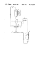
The FIGURE is a generalized schematical diagram of the chemical heat pipe employing the molar increase self-driving process of this invention.
BEST MODE FOR CARRYING OUT THE INVENTION
According to the FIGURE, gaseous reactants 3 (described below) at ambient pressures are compressed in a conventional compressor 6 to a predetermined pressure and displaced to a reactor 12 adjacent to a heat source 18. In reactor 12, the gaseous reactants undergo an endothermic chemical reaction, preferably in the presence of catalysts 15 (described below) resulting in reaction products 21. Typically, the endothermic reaction requires the addition of heat through heat source 18. The compression afforded by compressor 6 is insufficient to elevate the reactants to a temperature sufficient to react. Thus, the predetermined pressure increase in combination with the addition of heat should be sufficient to enable the endothermic reaction to proceed.
The reactants (chemicals) can be from a source 45 and/or recycled reactants 42. The chemicals used in this system should be such that the reaction results in an increase in moles. This increase in moles is preferably greater than about 150% of the original reactants. For chemical systems with an increase in moles less than about 150%, the attendant advantages afforded by this system are offset by the energy losses due to friction, conduction, etc. There are a variety of chemical systems generically described as simple, reversible reaction systems which are particularly adapted for use in chemical heat pipes. Exemplary systems comprise methylcyclohexane/toluene, SO3 /SO2, cyclohexane/benzene and the steam reforming system depicted below.
CH.sub.4 +H.sub.2 O⃡CO+3H.sub.2
Those skilled in the art will conceive of other systems. It is preferable to use the methylcyclohexane/toluene system as a modest temperature chemical heat pipe because of the easy reversibility of the reaction.
The catalysts used will be determined by the chemical reactants used. Thus, for a methylcyclohexane/toluene system, the preferred catalysts are noble metals for the methylcyclohexane dehydrogenation and nickel or noble metals for the hydrogenation reaction.
Returning to the FIGURE, the reaction products 21, present in a larger number of moles, are displaced through an expander 30, such as a conventional turbine. The volumetric increase in reaction product is translated into mechanical energy. Turbine 30 is mechanically or electrically linked to compressor 6 so that the volumetric increase is used to compress the reactants 3 affording a self-driven transport system. The self-pumping configuration may comprise any positive displacement compression or expansion element or any other mechanical compressor/expander configuration such as an axial flow rotary compressor/expander. The pressure subsequent to expansion must be greater than the pressure associated with a system which contains no expander/compressor combination. Thus, the expander turbine provides sufficient energy to the compressor turbine in order to assure a net pressure increase allowing for turbine/compressor inefficiencies.
In a preferred embodiment of this invention, the hot reaction products are cooled through a heat exchange system 24 with the initial reactants 3 in order to raise their temperature. This heat exchange embodiment is particularly adapted for low temperature chemical heat pipe systems based upon the hydrogenation of toluene for the transportation of hydrogen or energy over a distance of several miles. A considerable advantage in system utility is gained if the conduit lines can remain uninsulated. If this is done, the methylcyclohexane feed stream will return from a remote location at a centrally ambient temperature, and it is efficient to regeneratively heat this stream by heat exchange with the reactant product stream to recover as much of the sensible and latent heat as possible. It is preferable to place the compressor of the self-powered chemical pump system between the regenerative exchanger and the dehydrogenation reactor in order to maximize the regenerative recovery of latent heat. This results in the incoming reactant stream vaporizing at a low temperature. It is also preferable to place the reactant products stream expander downstream of the regenerator so that the hydrocarbon component condenses at a relatively high temperature and is thereby capable of transferring most of its latent heat to the incoming methylcyclohexane stream. It is unusual that this system is desirable because it can be disadvantageous to the chemical pump system since it compresses a hot gas stream while expanding a relatively cold two-phase stream. However, it results in better temperature matching for the endothermic reaction process along with effective heat regeneration.
For systems where some of the heat of compression is used for regenerative heating, there exists a preferential amount of compression. This is a factor of about 2.5 for the methylcyclohexane system described here. Above this preferential compression range, the efficiency of the expander/compressor system falls because of increased regenerative heat transfer.
The expanded reaction product 33 subsequent to expansion 30 is self-driven and may be transported to a desired location. Preferably, the reaction products are transported to a second, exothermic reactor 36 where they are reacted, preferably with a catalyst 39, such as nickel yielding a source of energy. It is especially preferred that the expander 30 is separated from the exothermic reactor 36 by a distance greater than about one mile because at these distances, this system has its greatest advantages. Over these long distances, this system works better than the system described in commonly owned U.S. Pat. No. 4,346,752 because of the higher pressures at point 33 downstream of the endothermic reactor 12. Subsequent to the exothermic reaction and simultaneous transformation of reaction products into the reactants, the reactants 42 may be utilized for any general purpose or transported and used as a source of reactant to be compressed at compressor 6 and optionally heated through exchange with reaction products 21.
The thermodynamics for these systems are described empirically below.
EXPLANATION OF SYMBOLS
Cp : Specific heat at constant pressure
Cv : Specific heat at constant volume
ds: Entropy change
dq: Heat absorbed
ηc : Compressor efficiency
ηe : Expander efficiency
p: Pressure
R: Gas constant
T: Temperature
v: Molar volume
W: Work done by the system.
For a reversible adiabatic change of state:
Tds=dq=0                                                   (1)
For an ideal gas:
Cpdv/v+Cvdp/p=0                                            (2)
Reorganizing:
Cp/Cvdv/v+dp/p=0                                           (3)
Assuming Cp/Cv is a constant k:
klnv=lnp=k                                                 (4)
(constant of integration)
Or
pv.sup.k =k.sub.1                                          (5)
And
pv.sup.k =p.sub.1 v.sub.1.sup.k =p.sub.2 v.sub.2.sup.k = . . . (6)
Where
k=Cp/Cv                                                    (7)
Combining (5) and the ideal-gas equation for v,T
Tv.sup.k-1 =K.sub.2                                        (8)
Combining (5) and the ideal-gas equation for p,T
Tp.sup.1-k/k =K.sub.3                                      (9)
Substituting (6) into ##EQU1##
Rearranging ##EQU2##
Rearranging ##EQU3## Substitution ##EQU4## Ideal Gas Law ##EQU5##
Equations 14 and 15 give the theoretical adiabatic work per mole for either compression or expansion, when p1 always refers to the initial pressure for either gas.
The total work for an ideal compressor or expander cycle is given by ##EQU6## where the integral is given by Eq. 15. From Eq. 13 we see that ##EQU7## Combining Eqs. 15 and 17, Eq. 16 becomes ##EQU8##
Applicant's self-driven system is depicted empirically below. ##STR1## Therefore, the expressions for compression work and expander work are: ##EQU9##
In this system's self-driven mode, the work recovered from the expander turbine is used to power the compressor, and taking the sum of equations 19 and 20 as zero gives the discharge to inlet pressure ratio P4 /P1 generated. Assuming for simplicity an isothermal chemical reaction T3 =T2 and negligible pressure drop through the reactor P3 =P2, the self-pumping discharge to inlet pressure ratio is ##EQU10##
For conventional compressors and expanders having c and e efficiency respectively, discharge to inlet pressure ratio can be approximated by ##EQU11## Utilizing the above compressor and expander efficiencies, the "pump" discharge pressure ratios are substantial as shown in Table I below.
              TABLE I                                                     
______________________________________                                    
Pressure Ratio (Discharge-to-Unlet)                                       
Developed for Various Molar                                               
Multiplication and Inlet Compression                                      
Case I:     Isothermal Reactor                                            
            Compressor Efficiency = 80%                                   
            Expander Efficiency = 88%                                     
                          Output-to-Inlet                                 
Molar Ratio Compression Ratio                                             
                          Pressure Ratio*                                 
(n.sub.2 /n.sub.1)                                                        
            (P.sub.2 /P.sub.1)                                            
                          (P.sub.4 /P.sub.1) k = 1.071                    
______________________________________                                    
2.          2.            1.233                                           
            3.            1.405                                           
            5.            1.670                                           
            10.           2.142                                           
3.          2.            1.451                                           
            3.            1.817                                           
            5.            2.429                                           
            10.           3.643                                           
4.          2.            1.574                                           
            3.            2.063                                           
            5.            2.919                                           
            10.           4.720                                           
______________________________________                                    
 *Cp = 30 cal/deg. mole                                                   
EXAMPLE
Referring to the FIGURE, a stream comprising 0.9 moles methylcyclohexane, 0.1 mole toluene and 0.3 mole hydrogen at 25° C. and 2 atmospheres enters regenerator 24, is heated and at the entrance (3) of the compressor (6) is at 205° C. and 2 atmospheres. An 80% efficient compressor (6) compresses the reactants to 242° C. and 5 atmospheres. In the reactor 12, the reactants are heated by heat source (18) to 310° C. and 5 atmospheres. The methylcyclohexane is dehydrogenated in the presence of a noble metal catalyst forming 0.9 mole toluene, 0.1 mole methylcyclohexane and 2.7 moles hydrogen at 310° C. and 5 atmospheres. At the heat exchanger 24, the reaction products are cooled to 80° C. at 5 atmospheres. The reaction products are expanded to 59° C. and 2.1 atmospheres by an 88% efficient expander. The effective molar multiplication ratio is n2 /n1 =2.8/1.3=2.154 since most of the hydrocarbon component has condensed by the time the "toluene" stream enters the expander.
Table II (below) summarizes the range discharge pressures obtained for various compressor pressure ratios for a methylcyclohexane/toluene system (as described above) where the reactants are regeneratively heated by heat exchange with the product stream. The table details how the achievable pump discharge to inlet pressure ratio actually maximizes with an inlet compression ratio between 2 and 2.5 to 1 (4 to 5 atmospheres) and then begins to decrease. This is believed to be a consequence of the disparity between compressor outlet and expander inlet temperatures.
              TABLE II                                                    
______________________________________                                    
Pressure Ratio (Discharge-to-Inlet                                        
Developed in Self-Driven Chemical Heat                                    
Pipe Configuration with Regeneration                                      
Case II: Regenerative Reactor Configuration of FIG. 2                     
         Compressor Efficiency = 80%                                      
         Expander Efficiency = 88%                                        
         P.sub.1 = 2 atm. (inlet)                                         
P.sub.2 T.sub.2 T.sub.3  (P.sub.4 /P.sub.1)                               
                                P.sub.4 T.sub.4                           
______________________________________                                    
 3. atm.                                                                  
        221° C.                                                    
                80° C.                                             
                         1.034  2.069 atm.                                
                                        71° C.                     
 4.     233     "        1.047  2.094   64                                
 5.     242     "         1.050.                                          
                                2.099   59                                
 7.     257     "        1.040  2.079   51                                
10.     272     "        1.012  2.023   42                                
______________________________________                                    
Although this invention has been described in terms of a chemical heat pipe system for the long distance transport of heat or hydrogen, its utilization in any chemical system involving an increase in molar volumetric flow is feasible. Thus, exemplary alternate uses are reactor systems used to promote decomposition reactions such as dehydrogenation or dehydration.
This chemical pump system makes an advance to this field of art by providing a self-driven compressor to increase the system pressure to overcome friction and resistance enhancing long distance transport. In addition, it obviates the need for a one-way valve and liquid head to provide the driving force for the reactants.
It should be understood that the invention is not limited to the particular embodiment shown and modifications may be made without departing from the spirit or scope of this concept as defined by the following claims.

Claims (4)

We claim:
1. In a chemical heat pipe employing reversible endothermic/exothermic chemical reactions to transfer thermal energy between a heat source and a heat sink the method of self-driving at least one reactant substantially unidirectionally through said heat pipe comprising:
(a) compressing said reactant(s) with a compressor and heating said reactant(s) to a predetermined pressure and temperature sufficient to endothermically react said reactant(s) to form reaction product having at least a 150% molar increase thereby establishing said self-driving unidirectional flow;
(b) transferring heat from said reaction product to said reactants; and
(c) expanding said reaction product with an expander linked mechanically to said compressor whereby said expansion energy is sufficient to compress said reactants to said predetermined pressure while maintaining said self-driving unidirectional flow.
2. The method of claim 1 wherein a predetermined quantity of thermal energy is transferred from said reaction product to said reactants.
3. The method of claim 1 wherein said reactant comprises methylcyclohexane, cyclohexane, SO3 or CH4 /H2 O.
4. The method of claim 1 wherein said reaction product is transported over a distance greater than about one mile.
US06/936,048 1986-11-28 1986-11-28 Chemical heat pipe employing self-driven chemical pump based on a molar increase Expired - Fee Related US4712610A (en)

Priority Applications (1)

Application Number Priority Date Filing Date Title
US06/936,048 US4712610A (en) 1986-11-28 1986-11-28 Chemical heat pipe employing self-driven chemical pump based on a molar increase

Applications Claiming Priority (1)

Application Number Priority Date Filing Date Title
US06/936,048 US4712610A (en) 1986-11-28 1986-11-28 Chemical heat pipe employing self-driven chemical pump based on a molar increase

Publications (1)

Publication Number Publication Date
US4712610A true US4712610A (en) 1987-12-15

Family

ID=25468104

Family Applications (1)

Application Number Title Priority Date Filing Date
US06/936,048 Expired - Fee Related US4712610A (en) 1986-11-28 1986-11-28 Chemical heat pipe employing self-driven chemical pump based on a molar increase

Country Status (1)

Country Link
US (1) US4712610A (en)

Cited By (17)

* Cited by examiner, † Cited by third party
Publication number Priority date Publication date Assignee Title
US4875346A (en) * 1989-01-31 1989-10-24 The United States Of America As Represented By The Administrator Of The National Aeronautics And Space Administration Two-statge sorption type cryogenic refrigerator including heat regeneration system
US4951741A (en) * 1989-11-15 1990-08-28 Schuurman Eiko A Chemical heat pump system for producing heat and cold
EP0487241A1 (en) * 1990-11-19 1992-05-27 General Electric Company Heat exchange system
US5121606A (en) * 1986-06-12 1992-06-16 Sita Maschinenbau- Und Forschungs Gmbh Thermodynamic cyclic process
US5275000A (en) * 1992-08-17 1994-01-04 General Electric Company Reducing thermal deposits in endothermic fuel reactors of propulsion systems
US5291735A (en) * 1993-03-23 1994-03-08 United Technologies Corporation High efficiency, hydrogen-driven cooling device
US5347828A (en) * 1993-03-23 1994-09-20 United Technologies Corporation Organic hydride/metal hydride heat pump
ES2121512A1 (en) * 1989-08-02 1998-11-16 Talens Francisco Soriano Improvements to the subject of patent No. 8902745 for "Process and corresponding equipment for transferring heat between a cold source and a hot source"
US6116027A (en) * 1998-09-29 2000-09-12 Air Products And Chemicals, Inc. Supplemental air supply for an air separation system
US20030000213A1 (en) * 1999-12-17 2003-01-02 Christensen Richard N. Heat engine
US7347057B1 (en) 2003-12-12 2008-03-25 Cooling Technologies, Inc. Control of dual-heated absorption heat-transfer machines
US20080304958A1 (en) * 2007-06-07 2008-12-11 Norris James W Gas turbine engine with air and fuel cooling system
US20100251711A1 (en) * 2007-10-03 2010-10-07 Isentropic Limited Energy Storage
GB2493950A (en) * 2011-08-24 2013-02-27 Isentropic Ltd Apparatus for storing energy
WO2015114716A1 (en) * 2014-01-30 2015-08-06 パナソニックIpマネジメント株式会社 Heat transport system
US9512780B2 (en) 2013-07-31 2016-12-06 General Electric Company Heat transfer assembly and methods of assembling the same
US10302335B2 (en) * 2014-06-10 2019-05-28 Lg Chem, Ltd. Heat recovery apparatus

Citations (6)

* Cited by examiner, † Cited by third party
Publication number Priority date Publication date Assignee Title
US3258925A (en) * 1964-03-04 1966-07-05 Snecma Closed-cycle thermal machine
US3370420A (en) * 1965-10-19 1968-02-27 Aerojet General Co Thermally dissociative gas power conversion cycle
US3511049A (en) * 1968-10-07 1970-05-12 American Air Filter Co Motive fluid composition
US3738103A (en) * 1969-09-01 1973-06-12 Metallgesellschaft Ag Power plant process
US3943719A (en) * 1975-02-26 1976-03-16 Terry Lynn E Hydride-dehydride power system and methods
US4346752A (en) * 1981-01-19 1982-08-31 United Technologies Corporation Self-driven chemical heat pipe

Patent Citations (6)

* Cited by examiner, † Cited by third party
Publication number Priority date Publication date Assignee Title
US3258925A (en) * 1964-03-04 1966-07-05 Snecma Closed-cycle thermal machine
US3370420A (en) * 1965-10-19 1968-02-27 Aerojet General Co Thermally dissociative gas power conversion cycle
US3511049A (en) * 1968-10-07 1970-05-12 American Air Filter Co Motive fluid composition
US3738103A (en) * 1969-09-01 1973-06-12 Metallgesellschaft Ag Power plant process
US3943719A (en) * 1975-02-26 1976-03-16 Terry Lynn E Hydride-dehydride power system and methods
US4346752A (en) * 1981-01-19 1982-08-31 United Technologies Corporation Self-driven chemical heat pipe

Cited By (23)

* Cited by examiner, † Cited by third party
Publication number Priority date Publication date Assignee Title
US5121606A (en) * 1986-06-12 1992-06-16 Sita Maschinenbau- Und Forschungs Gmbh Thermodynamic cyclic process
US4875346A (en) * 1989-01-31 1989-10-24 The United States Of America As Represented By The Administrator Of The National Aeronautics And Space Administration Two-statge sorption type cryogenic refrigerator including heat regeneration system
ES2121512A1 (en) * 1989-08-02 1998-11-16 Talens Francisco Soriano Improvements to the subject of patent No. 8902745 for "Process and corresponding equipment for transferring heat between a cold source and a hot source"
US4951741A (en) * 1989-11-15 1990-08-28 Schuurman Eiko A Chemical heat pump system for producing heat and cold
EP0487241A1 (en) * 1990-11-19 1992-05-27 General Electric Company Heat exchange system
US5275000A (en) * 1992-08-17 1994-01-04 General Electric Company Reducing thermal deposits in endothermic fuel reactors of propulsion systems
US5291735A (en) * 1993-03-23 1994-03-08 United Technologies Corporation High efficiency, hydrogen-driven cooling device
US5347828A (en) * 1993-03-23 1994-09-20 United Technologies Corporation Organic hydride/metal hydride heat pump
US6116027A (en) * 1998-09-29 2000-09-12 Air Products And Chemicals, Inc. Supplemental air supply for an air separation system
US7062913B2 (en) * 1999-12-17 2006-06-20 The Ohio State University Heat engine
US20030000213A1 (en) * 1999-12-17 2003-01-02 Christensen Richard N. Heat engine
US7347057B1 (en) 2003-12-12 2008-03-25 Cooling Technologies, Inc. Control of dual-heated absorption heat-transfer machines
US20080304958A1 (en) * 2007-06-07 2008-12-11 Norris James W Gas turbine engine with air and fuel cooling system
US8127547B2 (en) 2007-06-07 2012-03-06 United Technologies Corporation Gas turbine engine with air and fuel cooling system
US8826664B2 (en) 2007-10-03 2014-09-09 Isentropic Limited Energy storage
US20100251711A1 (en) * 2007-10-03 2010-10-07 Isentropic Limited Energy Storage
US20100257862A1 (en) * 2007-10-03 2010-10-14 Isentropic Limited Energy Storage
US8656712B2 (en) 2007-10-03 2014-02-25 Isentropic Limited Energy storage
GB2493950A (en) * 2011-08-24 2013-02-27 Isentropic Ltd Apparatus for storing energy
GB2493950B (en) * 2011-08-24 2016-01-06 Isentropic Ltd Energy storage apparatus
US9512780B2 (en) 2013-07-31 2016-12-06 General Electric Company Heat transfer assembly and methods of assembling the same
WO2015114716A1 (en) * 2014-01-30 2015-08-06 パナソニックIpマネジメント株式会社 Heat transport system
US10302335B2 (en) * 2014-06-10 2019-05-28 Lg Chem, Ltd. Heat recovery apparatus

Similar Documents

Publication Publication Date Title
US4712610A (en) Chemical heat pipe employing self-driven chemical pump based on a molar increase
US5392606A (en) Self-contained small utility system
EP1760275B1 (en) Heat cycle method
EP0703420A2 (en) Energy converter
US20020148225A1 (en) Energy conversion system
JPS61229905A (en) Mechanical generation of power
JPS5857220B2 (en) Energy information
US4224796A (en) Method for converting heat energy to mechanical energy with 1,2-dichloro-1,1-difluoroethane
Ren et al. Parametric and economic analysis of high-temperature cascade organic Rankine cycle with a biphenyl and diphenyl oxide mixture
US4896509A (en) Working fluid for Rankine cycle
WO2020147918A1 (en) Turbine system
US4651531A (en) Working fluids for Rankine cycle
Lovegrove Thermodynamic limits on the performance of a solar thermochemical energy storage system
US4562995A (en) Working fluids for Rankine cycle
Gandia et al. Effect of the design variables on the energy performance and size parameters of a heat transformer based on the system acetone/H2/2‐propanol
Cacciola et al. Influence of hydrogen-permeable membranes upon the efficiency of the high-temperature chemical heat pumps based on cyclohexane dehydrogenation-benzene hydrogenation reactions
Aristov et al. High‐temperature chemical heat pump based on reversible catalytic reactions of cyclohexane‐dehydrogenation/benzene‐hydrogenation: Comparison of the potentialities of different flow diagrams
US5445217A (en) Device for the production of cold and/or heat by solid-gas reaction
Iqbal Advantages of using mixtures as working fluids in geothermal binary cycles
Carden Direct work output from thermochemical energy transfer systems
GB2565863A (en) Turbine system
CN114876587B (en) Multistage power generation system for cascade utilization of energy
CN117450683B (en) Nested energy storage system
EP3966437B1 (en) Optimized cascade organic rankine cycle
Iqbal Use of mixtures as working fluids in ocean thermal energy conversion cycles

Legal Events

Date Code Title Description
AS Assignment

Owner name: UNITED TECHNOLOGIES CORPORATION, HARTFORD CT. A CO

Free format text: ASSIGNMENT OF ASSIGNORS INTEREST.;ASSIGNORS:KESTEN, ARTHUR S.;HAUGHT, ALAN F.;COUCH, HAROLD T.;REEL/FRAME:004638/0226;SIGNING DATES FROM 19861104 TO 19861124

Owner name: UNITED TECHNOLOGIES CORPORATION, A CORP. OF DE.,CO

Free format text: ASSIGNMENT OF ASSIGNORS INTEREST;ASSIGNORS:KESTEN, ARTHUR S.;HAUGHT, ALAN F.;COUCH, HAROLD T.;SIGNING DATES FROM 19861104 TO 19861124;REEL/FRAME:004638/0226

FPAY Fee payment

Year of fee payment: 4

FPAY Fee payment

Year of fee payment: 8

REMI Maintenance fee reminder mailed
LAPS Lapse for failure to pay maintenance fees
FP Lapsed due to failure to pay maintenance fee

Effective date: 19991215

STCH Information on status: patent discontinuation

Free format text: PATENT EXPIRED DUE TO NONPAYMENT OF MAINTENANCE FEES UNDER 37 CFR 1.362