US20110127004A1 - Regenerative thermal energy storage apparatus for an adiabatic compressed air energy storage system - Google Patents
Regenerative thermal energy storage apparatus for an adiabatic compressed air energy storage system Download PDFInfo
- Publication number
- US20110127004A1 US20110127004A1 US12/627,320 US62732009A US2011127004A1 US 20110127004 A1 US20110127004 A1 US 20110127004A1 US 62732009 A US62732009 A US 62732009A US 2011127004 A1 US2011127004 A1 US 2011127004A1
- Authority
- US
- United States
- Prior art keywords
- pressure vessel
- energy storage
- pressure
- thermal energy
- wall
- Prior art date
- Legal status (The legal status is an assumption and is not a legal conclusion. Google has not performed a legal analysis and makes no representation as to the accuracy of the status listed.)
- Abandoned
Links
- 238000004146 energy storage Methods 0.000 title claims abstract description 41
- 230000001172 regenerating effect Effects 0.000 title 1
- 238000000034 method Methods 0.000 claims abstract description 19
- 239000012530 fluid Substances 0.000 claims abstract description 18
- 238000004891 communication Methods 0.000 claims abstract description 17
- 239000004567 concrete Substances 0.000 claims description 39
- 239000000463 material Substances 0.000 claims description 7
- 238000009413 insulation Methods 0.000 claims description 5
- 239000004575 stone Substances 0.000 claims description 5
- 239000011159 matrix material Substances 0.000 claims description 4
- 229910000831 Steel Inorganic materials 0.000 claims description 3
- 239000010959 steel Substances 0.000 claims description 3
- 239000011810 insulating material Substances 0.000 claims 1
- 239000003570 air Substances 0.000 description 94
- 230000006835 compression Effects 0.000 description 21
- 238000007906 compression Methods 0.000 description 21
- 238000010276 construction Methods 0.000 description 6
- VNWKTOKETHGBQD-UHFFFAOYSA-N methane Chemical compound C VNWKTOKETHGBQD-UHFFFAOYSA-N 0.000 description 6
- 238000010248 power generation Methods 0.000 description 4
- 239000011435 rock Substances 0.000 description 4
- 239000002689 soil Substances 0.000 description 4
- OKTJSMMVPCPJKN-UHFFFAOYSA-N Carbon Chemical compound [C] OKTJSMMVPCPJKN-UHFFFAOYSA-N 0.000 description 3
- 238000003491 array Methods 0.000 description 3
- 230000008901 benefit Effects 0.000 description 3
- 229910052799 carbon Inorganic materials 0.000 description 3
- 230000005611 electricity Effects 0.000 description 3
- 238000004519 manufacturing process Methods 0.000 description 3
- 239000003345 natural gas Substances 0.000 description 3
- 238000003303 reheating Methods 0.000 description 3
- 239000011150 reinforced concrete Substances 0.000 description 3
- 239000012080 ambient air Substances 0.000 description 2
- 239000000919 ceramic Substances 0.000 description 2
- 238000005338 heat storage Methods 0.000 description 2
- 239000003921 oil Substances 0.000 description 2
- 150000003839 salts Chemical class 0.000 description 2
- 239000011232 storage material Substances 0.000 description 2
- 230000008646 thermal stress Effects 0.000 description 2
- 229910001018 Cast iron Inorganic materials 0.000 description 1
- 230000015572 biosynthetic process Effects 0.000 description 1
- 230000003292 diminished effect Effects 0.000 description 1
- 238000010304 firing Methods 0.000 description 1
- 239000000446 fuel Substances 0.000 description 1
- 239000007789 gas Substances 0.000 description 1
- 230000010354 integration Effects 0.000 description 1
- 239000011344 liquid material Substances 0.000 description 1
- 239000002480 mineral oil Substances 0.000 description 1
- 235000010446 mineral oil Nutrition 0.000 description 1
- 150000002823 nitrates Chemical class 0.000 description 1
- 239000012782 phase change material Substances 0.000 description 1
- 239000011343 solid material Substances 0.000 description 1
- 230000035882 stress Effects 0.000 description 1
Images


Classifications
-
- F—MECHANICAL ENGINEERING; LIGHTING; HEATING; WEAPONS; BLASTING
- F02—COMBUSTION ENGINES; HOT-GAS OR COMBUSTION-PRODUCT ENGINE PLANTS
- F02C—GAS-TURBINE PLANTS; AIR INTAKES FOR JET-PROPULSION PLANTS; CONTROLLING FUEL SUPPLY IN AIR-BREATHING JET-PROPULSION PLANTS
- F02C6/00—Plural gas-turbine plants; Combinations of gas-turbine plants with other apparatus; Adaptations of gas-turbine plants for special use
- F02C6/14—Gas-turbine plants having means for storing energy, e.g. for meeting peak loads
- F02C6/16—Gas-turbine plants having means for storing energy, e.g. for meeting peak loads for storing compressed air
-
- F—MECHANICAL ENGINEERING; LIGHTING; HEATING; WEAPONS; BLASTING
- F02—COMBUSTION ENGINES; HOT-GAS OR COMBUSTION-PRODUCT ENGINE PLANTS
- F02C—GAS-TURBINE PLANTS; AIR INTAKES FOR JET-PROPULSION PLANTS; CONTROLLING FUEL SUPPLY IN AIR-BREATHING JET-PROPULSION PLANTS
- F02C7/00—Features, components parts, details or accessories, not provided for in, or of interest apart form groups F02C1/00 - F02C6/00; Air intakes for jet-propulsion plants
- F02C7/08—Heating air supply before combustion, e.g. by exhaust gases
- F02C7/10—Heating air supply before combustion, e.g. by exhaust gases by means of regenerative heat-exchangers
-
- F—MECHANICAL ENGINEERING; LIGHTING; HEATING; WEAPONS; BLASTING
- F05—INDEXING SCHEMES RELATING TO ENGINES OR PUMPS IN VARIOUS SUBCLASSES OF CLASSES F01-F04
- F05D—INDEXING SCHEME FOR ASPECTS RELATING TO NON-POSITIVE-DISPLACEMENT MACHINES OR ENGINES, GAS-TURBINES OR JET-PROPULSION PLANTS
- F05D2220/00—Application
- F05D2220/60—Application making use of surplus or waste energy
-
- F—MECHANICAL ENGINEERING; LIGHTING; HEATING; WEAPONS; BLASTING
- F05—INDEXING SCHEMES RELATING TO ENGINES OR PUMPS IN VARIOUS SUBCLASSES OF CLASSES F01-F04
- F05D—INDEXING SCHEME FOR ASPECTS RELATING TO NON-POSITIVE-DISPLACEMENT MACHINES OR ENGINES, GAS-TURBINES OR JET-PROPULSION PLANTS
- F05D2260/00—Function
- F05D2260/42—Storage of energy
-
- F—MECHANICAL ENGINEERING; LIGHTING; HEATING; WEAPONS; BLASTING
- F28—HEAT EXCHANGE IN GENERAL
- F28D—HEAT-EXCHANGE APPARATUS, NOT PROVIDED FOR IN ANOTHER SUBCLASS, IN WHICH THE HEAT-EXCHANGE MEDIA DO NOT COME INTO DIRECT CONTACT
- F28D20/00—Heat storage plants or apparatus in general; Regenerative heat-exchange apparatus not covered by groups F28D17/00 or F28D19/00
- F28D2020/0004—Particular heat storage apparatus
- F28D2020/0021—Particular heat storage apparatus the heat storage material being enclosed in loose or stacked elements
-
- F—MECHANICAL ENGINEERING; LIGHTING; HEATING; WEAPONS; BLASTING
- F28—HEAT EXCHANGE IN GENERAL
- F28D—HEAT-EXCHANGE APPARATUS, NOT PROVIDED FOR IN ANOTHER SUBCLASS, IN WHICH THE HEAT-EXCHANGE MEDIA DO NOT COME INTO DIRECT CONTACT
- F28D20/00—Heat storage plants or apparatus in general; Regenerative heat-exchange apparatus not covered by groups F28D17/00 or F28D19/00
- F28D2020/0065—Details, e.g. particular heat storage tanks, auxiliary members within tanks
- F28D2020/0082—Multiple tanks arrangements, e.g. adjacent tanks, tank in tank
-
- Y—GENERAL TAGGING OF NEW TECHNOLOGICAL DEVELOPMENTS; GENERAL TAGGING OF CROSS-SECTIONAL TECHNOLOGIES SPANNING OVER SEVERAL SECTIONS OF THE IPC; TECHNICAL SUBJECTS COVERED BY FORMER USPC CROSS-REFERENCE ART COLLECTIONS [XRACs] AND DIGESTS
- Y02—TECHNOLOGIES OR APPLICATIONS FOR MITIGATION OR ADAPTATION AGAINST CLIMATE CHANGE
- Y02E—REDUCTION OF GREENHOUSE GAS [GHG] EMISSIONS, RELATED TO ENERGY GENERATION, TRANSMISSION OR DISTRIBUTION
- Y02E60/00—Enabling technologies; Technologies with a potential or indirect contribution to GHG emissions mitigation
- Y02E60/16—Mechanical energy storage, e.g. flywheels or pressurised fluids
Definitions
- Embodiments of the invention relate generally to compressed air energy storage (CAES) systems and, more particularly, to thermal energy storage (TES) systems in an adiabatic CAES system.
- CAES compressed air energy storage
- TES thermal energy storage
- CAES systems allow for the storage of electrical energy without producing substantial emissions and/or consuming vast quantities of natural resources.
- CAES systems typically include a compression train having one or more compressors. The one or more compressors compress intake air in a compression stage for storage in a cavern, porous rock formation, depleted natural gas/oil field, or other compressed air storage component. The compressed air is then later used to drive turbines to produce electrical energy in an energy generation stage, which can in turn be provided to the utility grid. Often, if utility energy is used to power the compression train during the compression stage, the compression train operates during the off-peak hours of utility plants. The energy generation stage of the CAES in turn typically operates during high power demand times.
- energy from renewable sources such as energy from wind turbines or solar panel arrays, may be used to power the compression train during the compression stage to compress and deliver air to the compressed air storage location (e.g., a cavern).
- the compression train may be operated during times other than off-peak hours, and existing utility energy may be preserved.
- One type of CAES system is known as a diabatic-CAES system.
- heat generated by the compression train is typically lost to the ambient environment. That is, the heat of compression may be lost to the ambient in intercoolers and what heat is left when entering the cavern or other compressed air storage component is diminished as the compressed air mixes with the cavern air and further cools to ambient temperature during storage.
- the compressed air stored in the cavern or compressed air storage component is to be used to drive one or more turbines to produce electrical energy
- the compressed air is typically reheated prior to entering the turbines.
- This reheating step is typically performed using a natural gas-fired combustor and a recuperator positioned between the compressed air storage component and the one or more turbines. Due to this reheating step, the overall efficiency of the diabatic-CAES system is reduced, and the use of natural gas to fuel the combustor leads to carbon emissions and natural resource consumption.
- Adiabatic-CAES, or ACAES systems are capable of improving system efficiency by capturing and storing the heat of compression for later use.
- one or more thermal energy storage (TES) units are positioned between the compressor and the cavern.
- TES thermal energy storage
- a TES unit contains therein a medium for heat storage, such as concrete, stone, a fluid (e.g., oil), a molten salt, or a phase-change material.
- Hot air from the compression stage is passed through the TES unit, thereby transferring its heat of compression to the medium in the process.
- ACAES systems do not lose all of the heat generated by the compression train, but instead store some of the heat within the TES unit or units. The compressed air then enters the cavern at or near ambient temperature.
- ACAES systems do not necessitate additional natural gas to reheat the compressed air exiting the cavern or other compressed air storage component.
- ACAES systems provide improved efficiency over diabatic-CAES systems, with fewer (if any) carbon emissions and little to no natural resource consumption.
- TES units built to effectively store heat generated during the compression cycle of the compression train are constructed to withstand the high heat fluctuations and high pressure associated with ACAES systems.
- the compressed air temperature exiting the compression train may vary from 250° C. to 750° C., while the temperature of the compressed air entering the TES unit from the cavern is near ambient temperature.
- the TES units are designed to withstand pressures of 65-85 bar.
- current proposals for TES units involve the construction of large concrete cylinders filled with a medium for heat storage. Due to their large diameter, these TES units are formed having thick, pre-stressed and steel-reinforced concrete walls, which enable the TES unit to withstand the high tension forces in the wall created by the pressure therein.
- aspects of the invention provide a system and method for a TES system having at least one TES unit configured to withstand high temperatures and pressures.
- the at least one TES unit is constructed and arranged such that the wall of the at least one TES unit has a minimal thickness.
- a thermal energy storage system comprising a plurality of pressure vessels arranged in close proximity to one another, each of the pressure vessels having a wall comprising an outer surface and an inner surface spaced from the outer surface by a respective wall thickness and surrounding an interior volume of the pressure vessel.
- the interior volume has a first end in fluid communication with one or more compressors and one or more turbines and a second end in fluid communication with at least one of one or more additional compressors, one or more additional turbines, and at least one compressed air storage component.
- the thermal energy storage system further comprises a thermal storage medium positioned in the interior volume of each of the plurality of pressure vessels.
- a method of forming a thermal energy storage system comprising forming a first pressure vessel, the first pressure vessel having a wall constructed to have a predetermined height and thickness, wherein an inner surface of the wall of the first pressure vessel bounds an interior volume therein, and forming a second pressure vessel, the second pressure vessel constructed to have a wall of predetermined height and thickness, wherein an inner surface of the wall of the second pressure vessel bounds an interior volume therein.
- the method further comprises disposing a porous thermal storage medium within the interior volume of each of the first and second pressure vessels, and arranging the first pressure vessel and the second pressure vessel in close proximity to one another.
- the method comprises connecting a first end of each of the first and second pressure vessels to one or more compressors and to one or more turbines such that each of the first and second pressure vessels is in fluid communication with the one or more compressors and the one or more turbines, and connecting a second end of each of the first and second pressure vessels to at least one of one or more additional compressors, one or more additional turbines, and one or more compressed air storage components such that each of the first and second pressure vessels is in fluid communication with at least one of the one or more additional compressors, the one or more additional turbines, and the one or more compressed air storage components.
- a thermal energy storage apparatus comprising a first concrete cylindrical wall bounding a first interior volume and a second concrete cylindrical wall bounding a second interior volume, wherein the second concrete cylindrical wall is arranged within the first interior volume of the first concrete cylindrical wall such that the first concrete cylindrical wall and the second concrete cylindrical wall are coaxial.
- the thermal energy storage apparatus further comprises a porous thermal matrix material disposed within the first interior volume of the first concrete cylindrical wall and within the second interior volume of the second concrete cylindrical wall.
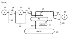
- FIG. 1 is a schematic arrangement of an ACAES system according to an embodiment of the present invention.
- FIG. 2 is a cross-sectional view of a TES system in accordance with an embodiment of the present invention.
- FIG. 3 is a cross-sectional view of a TES system in accordance with another embodiment of the present invention.
- FIG. 4 is a plan view of a TES system in accordance with the embodiment of FIG. 3 .
- FIG. 5 is a cross-sectional view of a TES system in accordance with another embodiment of the present invention.
- FIG. 6 is a cross-sectional view of a TES system placed within the shaft of a cavern in accordance with another embodiment of the present invention.
- a system comprising at least one TES unit configured to allow the at least one TES unit to withstand high pressure and temperature fluctuations while maintaining minimal wall thickness.
- ACAES system 100 comprises an electric motor 102 coupled to a low-pressure compressor 104 .
- Electric motor 102 may be electrically powered via conventional means, i.e., the utility grid, during off-peak utility hours. Alternatively, electric motor 102 may be powered by electricity provided via wind farms, solar arrays, or other renewable sources.
- Electric motor 102 powers low-pressure compressor 104 such that low-pressure compressor 104 pressurizes intake air 106 . Pressurized air 108 from low-pressure compressor 104 is then provided to a high-pressure compressor 112 to enable the air to undergo further compression.
- high-pressure compressor 112 is powered by an electric motor 110 .
- Electric motor 110 may also be powered by the utility grid or by renewable sources such as wind farms and solar arrays. While ACAES system 100 shows the use of two compressors in a “compression train”, it is to be understood that more or fewer compressors could be used.
- the at least one TES unit 116 typically includes a porous thermal storage medium disposed therein, the porous thermal storage medium capable of retaining a substantial amount of the heat emitted by air 114 as it passes through the at least one TES unit 116 .
- the porous thermal storage medium may be a variety of solid materials, such as natural stone (e.g., split rocks and/or pebbles), ceramics, concrete, cast iron, or a combination of ceramics and salt.
- the porous thermal storage medium may be a liquid material, such as a combination of nitrate salt and mineral oil.
- the advantage of using naturally occurring thermal storage medium materials such as split rocks and/or pebbles is that material costs can be greatly lowered, and manufacturing/transport energy can be saved, given that such naturally occurring materials are readily available.
- the split rocks and/or pebbles should be of a suitable size to have a high surface-to-volume ratio and temperature resistance.
- compressed air 118 exits the at least one TES unit 116 at a lowered temperature to enable compressed air 118 to be stored in a cavern 122 or other compressed air storage component.
- compressed air 118 Prior to entering cavern 122 , though, compressed air 118 may need to be further cooled by an optional intercooler 120 such that compressed air 118 enters cavern 122 at a maximum temperature of approximately 50° C., for example.
- Cavern 122 enables air pressurized to a level of about 60-80 bar to be stored for an extended period of time without significant compression losses.
- compressed air 124 may be discharged from cavern 122 when use of the stored air is desired for the generation of electricity.
- Compressed air 124 exits cavern 122 and re-enters the at least one TES unit 116 at a temperature of approximately 20-50° C.
- the compressed air passes through the porous thermal storage medium of the at least one TES unit 116 , it is reheated to a temperature of up to 600° C., a temperature near that of heated air 114 previously discharged from high-pressure compressor 112 .
- This reheated compressed air 126 which at this stage is pressurized to a level of about 55-75 bars, then enters a turbine 128 , which is powered by reheated compressed air 126 . More than one turbine 128 could be used, forming an “expansion train”. Unlike diabatic-CAES systems, compressed air 126 has been reheated within the at least one TES unit 116 , and thus there is no need for additional heat recuperation or gas firing at the steam turbine to reheat the compressed air. As turbine 128 operates, exhaust air 130 is discharged therefrom, and steam turbine 128 powers an electrical generator 132 . Electrical energy generated by generator 132 may then be provided to the utility grid for consumption. As can readily appreciated, ACAES system 100 represents a method of generating electricity that can greatly reduce, if not eliminate, natural resource consumption and/or carbon emissions in the production of electrical energy.
- more than one TES unit 116 may be utilized such that only one TES unit is fluidly connected to a cavern or other compressed air storage component, while one or more intermediate TES units are disposed between the compression and/or expansion trains and the TES unit fluidly connected to the compressed air storage component.
- these intermediate TES units are fluidly connected to the one or more compressors and one or more turbines at each end thereof.
- the at least one TES unit 116 may be subjected to significant pressures (65-85 bar) and temperatures (up to 650° C.) during operation of ACAES system 100 .
- the at least one TES unit 116 should be constructed to withstand such high pressure and temperature levels.
- FIG. 2 a TES system 216 in accordance with an embodiment of the invention is shown. It is to be understood that TES system 216 may be used as the at least one TES unit 116 shown in FIG. 1 , whereby TES system 216 is capable of withstanding the significant pressures and temperatures associated with operation of an ACAES system.
- FIG. 2 illustrates a cross-sectional view of TES system 216 .
- TES system 216 comprises two separate coaxial cylindrical pressure vessels 218 , 220 .
- Pressure vessel 218 comprises a wall 222 having a predetermined length and diameter, wherein the length of wall 222 may range from 10-30 m, while the diameter may range from 3-6 m. However, pressure vessel 218 is not limited to such length and diameter ranges, and may be larger or smaller in both length and diameter.
- pressure vessel 220 comprises a wall 224 having a predetermined length and diameter, wherein the length of wall 224 may range from 10-30 m and the diameter may range from 5-12 m.
- pressure vessel 220 As with pressure vessel 218 , though, the length and diameter of pressure vessel 220 are not limited to the above ranges. Pressure vessels 218 , 220 are generally formed using reinforced concrete, but may be formed using any suitable material, including steel. Also, pressure vessels 218 , 220 are not limited to being cylindrical in shape, but could be formed having any suitable shape.
- pressure vessel 218 is disposed within the confines of an interior volume of pressure vessel 220 .
- An interior volume of pressure vessel 218 contains therein a porous thermal storage medium 226
- an interior volume of pressure vessel 220 contains therein a porous thermal storage medium 228 .
- Porous thermal storage media 226 , 228 may be composed of the same thermal storage material or, alternatively, could be composed of different thermal storage materials.
- TES system 216 is configured to receive compressed air from at least one compressor, whereby the compressed air enters the respective pressure vessels 218 , 220 at a first end 230 and exits respective pressure vessels 218 , 220 at a second end 232 such that the compressed air is capable of being stored in a compressed air storage unit or, alternatively, can be provided to additional compressors and/or turbines (in the case of a multi-stage ACAES system). Heat from the compressed air received from the at least one compressor may be stored in the respective porous thermal storage media 226 , 228 .
- the stored compressed air re-enters respective pressure vessels 218 , 220 at the second end 232 and is reheated as it passes through respective porous thermal storage media 226 , 228 .
- the reheated air then exits respective pressure vessels 218 , 220 at the first end 230 , where it is provided to one or more steam turbines to power an electrical generator.
- TES system 216 enables pressure vessels 218 , 220 to receive compressed air having differing respective pressure levels. That is, pressure vessel 218 may be configured to receive a high-pressure compressed air input from both the one or more compressors and the compressed air storage unit, while pressure vessel 220 may be configured to receive a low-pressure compressed air input from the one or more compressors and the compressed air storage unit. In one embodiment, pressure vessel 218 is configured to receive (and withstand) pressures of 40-80 bar, while pressure vessel 220 is configured to receive (and withstand) pressures of 5-20 bar.
- pressure vessel 218 As pressure vessel 218 has a smaller diameter (and thus lower tension forces) than pressure vessel 220 , pressure vessel 218 is capable of withstanding higher pressures, even though a thickness of wall 222 could be less than a thickness of wall 224 . Also, because pressure vessel 218 is disposed within the interior volume of pressure vessel 220 , the low-pressure compressed air passing through the porous thermal storage medium 228 acts to lessen the pressure differential between the compressed air passing through pressure vessel 218 and the air outside of pressure vessel 218 .
- wall 222 can be constructed having a substantially reduced thickness when compared to pressure vessels used in conventional TES systems. Furthermore, because pressure vessel 220 is subjected to low-pressure compressed air, the thickness of wall 224 can also be substantially smaller than the thickness of a conventional TES pressure vessel.
- heat losses from pressure vessel 218 are also reduced when compared to conventional TES systems, as the temperature difference between the compressed air passing through pressure vessel 218 and the compressed air passing through pressure vessel 220 is much less than the temperature difference between the compressed air passing through a conventional TES unit and the surrounding ambient air. As such, even though wall 222 is thinner than a conventional pressure vessel wall, heat losses are reduced due to the coaxial integrated configuration of pressure vessels 218 , 220 of TES system 216 .
- TES system 216 is made up of a combination of pressure vessel 218 and pressure vessel 220 , the respective pressure vessels 218 , 220 can be constructed to withstand high pressures and temperatures overall, but with reduced wall thicknesses. As such, cost and complexity of constructing and transporting TES system 216 is much less than that of typical TES systems, with the added benefit of smaller pressure vessels and, thus, a smaller overall TES system footprint.
- FIG. 3 schematically shows a TES system 316 comprising three separate pressure vessels 318 , 320 , 322 fluidly arranged in parallel.
- First pressure vessel 318 has a wall 324 surrounding a thermal storage medium 334
- second pressure vessel 320 has a wall 326 surrounding a thermal storage medium 336
- third pressure vessel 322 has a wall 328 surrounding a thermal storage medium 338 .
- respective pressure vessels 318 , 320 , 322 may be identically constructed, but embodiments of the present invention are not limited as such.
- Pressure vessels 318 , 320 , 322 are closely arranged to enable compressed air from at least one compressor to enter the respective pressure vessels at a first end 330 of pressure vessels 318 , 320 , 322 .
- the compressed air travels through pressure vessels 318 , 320 , 322 , whereby heat from the compressed air is captured and stored in respective thermal storage media 334 , 336 , 338 .
- the compressed air then exits the respective pressure vessels at a second end 332 of pressure vessels 318 , 320 , 322 , where it is stored in a cavern or other compressed air storage device or, alternatively, is provided to additional compressors and/or turbines, as similarly described above with respect to FIG. 2 .
- the stored compressed air reenters respective pressure vessels 318 , 320 , 322 at the second end 332 and is reheated as it passes through respective porous thermal storage media 334 , 336 , 338 .
- the reheated air then exits respective pressure vessels 318 , 320 , 322 at the first end 330 , where it is provided to one or more steam turbines to power an electrical generator.
- FIG. 3 shows three separate pressure vessels 318 , 320 , 322
- the present invention is not limited to a specific number of pressure vessels, and may comprise any number of closely arranged or packed pressure vessels.
- pressure vessels 318 , 320 , 322 are arranged in a triangular array such that respective walls 324 , 326 , 328 of pressure vessels 318 , 320 , 322 are located in close proximity to one another (e.g., within centimeters, and not more than a meter apart), as is illustrated in FIG. 4 .
- other geometrical arrangements such as a hexagonal array, can be used to ensure that the pressure vessels are closely located.
- an insulation layer 340 may be disposed only about the perimeter of the closely packed pressure vessels 318 , 320 , 322 , and thus heat losses, thermal stresses and/or thermal gradients within respective walls 324 , 326 , 328 may be minimized. In this manner, the design and construction of TES system 316 is simplified, since a separate insulation layer disposed about each of pressure vessels 318 , 320 , 322 is avoided.
- TES system 316 By utilizing a plurality of closely packed pressure vessels, TES system 316 is able to effectively withstand high temperatures and high pressures without necessitating a single TES unit having both a large diameter and substantial wall thickness requirements. As such, TES system 316 allows for effective thermal energy storage in an ACAES system with reduced system size and weight, thereby eliminating many construction and transport issues that may be associated with conventional TES systems.
- FIG. 5 illustrates another embodiment in accordance with the present invention.
- TES unit 416 comprises a pressure vessel having a cylindrical wall 418 encompassing a thermal storage medium 420 disposed therein.
- TES unit 416 operates similarly to TES systems 216 and 361 described above with respect to FIGS. 2 and 3 , whereby compressed air from at least on compressor enters TES unit 416 at a first end 422 .
- the compressed air passes through thermal storage medium 420 to allow heat from the compressed air to be captured and stored within TES unit 416 .
- the compressed air then exits TES unit 416 at a second end 424 , where it is stored in a cavern or other compressed air storage unit for later usage in power generation.
- Cylindrical wall 418 is preferably constructed to have a high length-to-diameter ratio using a strong material having a low thickness (e.g., steel). With such a low diameter, the thickness of cylindrical wall 418 can be smaller than the reinforced concrete walls of convention TES units, while the increased length of cylindrical wall 418 still enables a sufficient amount of thermal storage medium 420 to be disposed therein to effectively capture and store the heat needed for use in an ACAES system.
- FIG. 5 only shows a single TES unit 416 , it is envisioned that a plurality of such TES units can be arranged in parallel to form a closely packed group of TES units, as is similarly shown and discussed with respect to FIGS. 3-4 . Thus, an increased compressed air volume can be handled by multiple TES units 416 , but the reduced system size and weight of each individual TES unit 416 again eliminates many construction and transport issues that may be associated with conventional TES systems.
- TES system 516 illustrated in FIG. 6 comprises a TES unit 518 that is configured to be disposed below ground level.
- TES unit 518 comprises a wall 520 encompassing a porous thermal storage medium 522 therein.
- the operation of TES unit 518 is similar to that of the TES units described above with respect to FIGS. 2-5 , and thus the details of the operation will not be repeated.
- TES unit 518 is shown as a single unit, it is to be understood that TES unit 518 could be configured in various ways, including the arrangements described above with respect to FIGS. 2-5 .
- TES unit 518 is integrated into a shaft 524 of a cavern 526 , thereby surrounding wall 520 of TES unit 518 in bedrock/soil 528 such that TES unit 518 is disposed below ground level 530 .
- Compressed air from at least one compressor enters TES unit 518 at a first end 532 and exits TES unit 518 at a second end 534 .
- the compressed air is then stored in cavern 526 for eventual use in electrical power generation, as described above.
- TES unit 518 of TES system 516 As TES unit 518 of TES system 516 is located below ground level 530 , and wall 520 is surrounded by bedrock/soil 528 , the thickness of wall 520 (and the thickness of any insulation (not shown) surrounding wall 520 ) may be substantially reduced.
- Bedrock/soil 528 provides a natural counteraction to the high tension forces in wall 520 brought on by high pressures therein, and bedrock/soil 528 also provides natural insulation to reduce heat loss in the system. Additionally, integration of TES unit 518 in shaft 524 of cavern 526 may reduce the above-ground footprint of the ACAES plant.
- TES system 516 overcomes manufacturing and transport difficulties associated with some conventional TES systems, thereby reducing the costs and simplifying the implementation of a TES unit in an ACAES system.
- a thermal energy storage system comprising a plurality of pressure vessels arranged in close proximity to one another, each of the pressure vessels having a wall comprising an outer surface and an inner surface spaced from the outer surface by a respective wall thickness and surrounding an interior volume of the pressure vessel.
- the interior volume has a first end in fluid communication with one or more compressors and one or more turbines and a second end in fluid communication with at least one of one or more additional compressors, one or more additional turbines, and at least one compressed air storage component.
- the thermal energy storage system further comprises a thermal storage medium positioned in the interior volume of each of the plurality of pressure vessels.
- a method of forming a thermal energy storage system comprising forming a first pressure vessel, the first pressure vessel having a wall constructed to have a predetermined height and thickness, wherein an inner surface of the wall of the first pressure vessel bounds an interior volume therein, and forming a second pressure vessel, the second pressure vessel constructed to have a wall of predetermined height and thickness, wherein an inner surface of the wall of the second pressure vessel bounds an interior volume therein.
- the method further comprises disposing a porous thermal storage medium within the interior volume of each of the first and second pressure vessels, and arranging the first pressure vessel and the second pressure vessel in close proximity to one another.
- the method comprises connecting a first end of each of the first and second pressure vessels to one or more compressors and to one or more turbines such that each of the first and second pressure vessels is in fluid communication with the one or more compressors and the one or more turbines, and connecting a second end of each of the first and second pressure vessels to at least one of one or more additional compressors, one or more additional turbines, and one or more compressed air storage components such that each of the first and second pressure vessels is in fluid communication with at least one of the one or more additional compressors, the one or more additional turbines, and the one or more compressed air storage components.
- a thermal energy storage apparatus comprising a first concrete cylindrical wall bounding a first interior volume and a second concrete cylindrical wall bounding a second interior volume, wherein the second concrete cylindrical wall is arranged within the first interior volume of the first concrete cylindrical wall such that the first concrete cylindrical wall and the second concrete cylindrical wall are coaxial.
- the thermal energy storage apparatus further comprises a porous thermal matrix material disposed within the first interior volume of the first concrete cylindrical wall and within the second interior volume of the second concrete cylindrical wall.
Landscapes
- Engineering & Computer Science (AREA)
- Chemical & Material Sciences (AREA)
- Combustion & Propulsion (AREA)
- Mechanical Engineering (AREA)
- General Engineering & Computer Science (AREA)
- Filling Or Discharging Of Gas Storage Vessels (AREA)
Abstract
A system and method for a thermal energy storage system is disclosed, the thermal energy storage system comprising a plurality of pressure vessels arranged in close proximity to one another, each of the pressure vessels having a wall comprising an outer surface and an inner surface spaced from the outer surface by a respective wall thickness and surrounding an interior volume of the pressure vessel. The interior volume has a first end in fluid communication with one or more compressors and one or more turbines and a second end in fluid communication with at least one of one or more additional compressors, one or more additional turbines, and at least one compressed air storage component. The thermal energy storage system further comprises a thermal storage medium positioned in the interior volume of each of the plurality of pressure vessels.
Description
- Embodiments of the invention relate generally to compressed air energy storage (CAES) systems and, more particularly, to thermal energy storage (TES) systems in an adiabatic CAES system.
- CAES systems allow for the storage of electrical energy without producing substantial emissions and/or consuming vast quantities of natural resources. CAES systems typically include a compression train having one or more compressors. The one or more compressors compress intake air in a compression stage for storage in a cavern, porous rock formation, depleted natural gas/oil field, or other compressed air storage component. The compressed air is then later used to drive turbines to produce electrical energy in an energy generation stage, which can in turn be provided to the utility grid. Often, if utility energy is used to power the compression train during the compression stage, the compression train operates during the off-peak hours of utility plants. The energy generation stage of the CAES in turn typically operates during high power demand times. Alternatively, energy from renewable sources, such as energy from wind turbines or solar panel arrays, may be used to power the compression train during the compression stage to compress and deliver air to the compressed air storage location (e.g., a cavern). In this way, the compression train may be operated during times other than off-peak hours, and existing utility energy may be preserved.
- One type of CAES system is known as a diabatic-CAES system. In a diabatic-CAES system, heat generated by the compression train is typically lost to the ambient environment. That is, the heat of compression may be lost to the ambient in intercoolers and what heat is left when entering the cavern or other compressed air storage component is diminished as the compressed air mixes with the cavern air and further cools to ambient temperature during storage. Thus, when the compressed air stored in the cavern or compressed air storage component is to be used to drive one or more turbines to produce electrical energy, the compressed air is typically reheated prior to entering the turbines. This reheating step is typically performed using a natural gas-fired combustor and a recuperator positioned between the compressed air storage component and the one or more turbines. Due to this reheating step, the overall efficiency of the diabatic-CAES system is reduced, and the use of natural gas to fuel the combustor leads to carbon emissions and natural resource consumption.
- Adiabatic-CAES, or ACAES, systems are capable of improving system efficiency by capturing and storing the heat of compression for later use. In such a system, one or more thermal energy storage (TES) units are positioned between the compressor and the cavern. Typically, a TES unit contains therein a medium for heat storage, such as concrete, stone, a fluid (e.g., oil), a molten salt, or a phase-change material. Hot air from the compression stage is passed through the TES unit, thereby transferring its heat of compression to the medium in the process. Thus, unlike diabatic-CAES systems, ACAES systems do not lose all of the heat generated by the compression train, but instead store some of the heat within the TES unit or units. The compressed air then enters the cavern at or near ambient temperature.
- When the compressed air stored within the cavern or other compressed air storage unit is to be withdrawn to drive the one or more turbines to produce electrical energy, the compressed air passes back through the TES unit, thereby reheating the compressed air prior to entry into the turbine or turbines. In this way, ACAES systems do not necessitate additional natural gas to reheat the compressed air exiting the cavern or other compressed air storage component. Thus, ACAES systems provide improved efficiency over diabatic-CAES systems, with fewer (if any) carbon emissions and little to no natural resource consumption.
- TES units built to effectively store heat generated during the compression cycle of the compression train are constructed to withstand the high heat fluctuations and high pressure associated with ACAES systems. For example, the compressed air temperature exiting the compression train may vary from 250° C. to 750° C., while the temperature of the compressed air entering the TES unit from the cavern is near ambient temperature. Likewise, the TES units are designed to withstand pressures of 65-85 bar. To withstand such high temperatures and pressures, current proposals for TES units involve the construction of large concrete cylinders filled with a medium for heat storage. Due to their large diameter, these TES units are formed having thick, pre-stressed and steel-reinforced concrete walls, which enable the TES unit to withstand the high tension forces in the wall created by the pressure therein. However, construction of such thick concrete walls leads to substantial engineering difficulties and high costs, thereby reducing the feasibility of implementing an ACAES system as opposed to a less efficient diabatic-CAES system. Furthermore, high operating temperatures and temperature cycles induce damaging thermal stresses into the concrete walls, and these stresses are amplified as the concrete walls grow thicker.
- Therefore, it would be desirable to design an apparatus and method that overcomes the aforementioned drawbacks related to TES unit construction.
- Aspects of the invention provide a system and method for a TES system having at least one TES unit configured to withstand high temperatures and pressures. The at least one TES unit is constructed and arranged such that the wall of the at least one TES unit has a minimal thickness.
- In accordance with one aspect of the invention, a thermal energy storage system is disclosed, the thermal energy storage system comprising a plurality of pressure vessels arranged in close proximity to one another, each of the pressure vessels having a wall comprising an outer surface and an inner surface spaced from the outer surface by a respective wall thickness and surrounding an interior volume of the pressure vessel. The interior volume has a first end in fluid communication with one or more compressors and one or more turbines and a second end in fluid communication with at least one of one or more additional compressors, one or more additional turbines, and at least one compressed air storage component. The thermal energy storage system further comprises a thermal storage medium positioned in the interior volume of each of the plurality of pressure vessels.
- In accordance with another aspect of the invention, a method of forming a thermal energy storage system is disclosed, the method comprising forming a first pressure vessel, the first pressure vessel having a wall constructed to have a predetermined height and thickness, wherein an inner surface of the wall of the first pressure vessel bounds an interior volume therein, and forming a second pressure vessel, the second pressure vessel constructed to have a wall of predetermined height and thickness, wherein an inner surface of the wall of the second pressure vessel bounds an interior volume therein. The method further comprises disposing a porous thermal storage medium within the interior volume of each of the first and second pressure vessels, and arranging the first pressure vessel and the second pressure vessel in close proximity to one another. Also, the method comprises connecting a first end of each of the first and second pressure vessels to one or more compressors and to one or more turbines such that each of the first and second pressure vessels is in fluid communication with the one or more compressors and the one or more turbines, and connecting a second end of each of the first and second pressure vessels to at least one of one or more additional compressors, one or more additional turbines, and one or more compressed air storage components such that each of the first and second pressure vessels is in fluid communication with at least one of the one or more additional compressors, the one or more additional turbines, and the one or more compressed air storage components.
- In accordance with yet another aspect of the invention, a thermal energy storage apparatus is disclosed, the thermal energy storage apparatus comprising a first concrete cylindrical wall bounding a first interior volume and a second concrete cylindrical wall bounding a second interior volume, wherein the second concrete cylindrical wall is arranged within the first interior volume of the first concrete cylindrical wall such that the first concrete cylindrical wall and the second concrete cylindrical wall are coaxial. The thermal energy storage apparatus further comprises a porous thermal matrix material disposed within the first interior volume of the first concrete cylindrical wall and within the second interior volume of the second concrete cylindrical wall.
- Various other features and advantages will be made apparent from the following detailed description and the drawings.
- The drawings illustrate preferred embodiments presently contemplated for carrying out the invention.
- In the drawings:
-
FIG. 1 is a schematic arrangement of an ACAES system according to an embodiment of the present invention. -
FIG. 2 is a cross-sectional view of a TES system in accordance with an embodiment of the present invention. -
FIG. 3 is a cross-sectional view of a TES system in accordance with another embodiment of the present invention. -
FIG. 4 is a plan view of a TES system in accordance with the embodiment ofFIG. 3 . -
FIG. 5 is a cross-sectional view of a TES system in accordance with another embodiment of the present invention. -
FIG. 6 is a cross-sectional view of a TES system placed within the shaft of a cavern in accordance with another embodiment of the present invention. - According to embodiments of the invention, a system is provided that comprises at least one TES unit configured to allow the at least one TES unit to withstand high pressure and temperature fluctuations while maintaining minimal wall thickness.
- First, referring to
FIG. 1 , a schematic arrangement of the primary elements of an ACAES system is shown. ACAESsystem 100 comprises anelectric motor 102 coupled to a low-pressure compressor 104.Electric motor 102 may be electrically powered via conventional means, i.e., the utility grid, during off-peak utility hours. Alternatively,electric motor 102 may be powered by electricity provided via wind farms, solar arrays, or other renewable sources.Electric motor 102 powers low-pressure compressor 104 such that low-pressure compressor 104 pressurizesintake air 106. Pressurizedair 108 from low-pressure compressor 104 is then provided to a high-pressure compressor 112 to enable the air to undergo further compression. Similar to low-pressure compressor 104, high-pressure compressor 112 is powered by anelectric motor 110.Electric motor 110 may also be powered by the utility grid or by renewable sources such as wind farms and solar arrays. While ACAESsystem 100 shows the use of two compressors in a “compression train”, it is to be understood that more or fewer compressors could be used. - As the air passes through respective low-
pressure compressor 104 and high-pressure compressor 112, the air is pressurized to a level of 65-85 bar and subsequently heated to a temperature of up to 650° C. This pressurized,heated air 114 then enters at least one thermal energy storage (TES)unit 116. The at least oneTES unit 116 typically includes a porous thermal storage medium disposed therein, the porous thermal storage medium capable of retaining a substantial amount of the heat emitted byair 114 as it passes through the at least oneTES unit 116. The porous thermal storage medium may be a variety of solid materials, such as natural stone (e.g., split rocks and/or pebbles), ceramics, concrete, cast iron, or a combination of ceramics and salt. Alternatively, the porous thermal storage medium may be a liquid material, such as a combination of nitrate salt and mineral oil. However, the advantage of using naturally occurring thermal storage medium materials such as split rocks and/or pebbles is that material costs can be greatly lowered, and manufacturing/transport energy can be saved, given that such naturally occurring materials are readily available. If natural stone is to be used as the porous thermal storage medium, the split rocks and/or pebbles should be of a suitable size to have a high surface-to-volume ratio and temperature resistance. - After
heated air 114 passes through the at least oneTES unit 116,compressed air 118 exits the at least oneTES unit 116 at a lowered temperature to enablecompressed air 118 to be stored in acavern 122 or other compressed air storage component. Prior to enteringcavern 122, though,compressed air 118 may need to be further cooled by anoptional intercooler 120 such thatcompressed air 118 enterscavern 122 at a maximum temperature of approximately 50° C., for example.Cavern 122 enables air pressurized to a level of about 60-80 bar to be stored for an extended period of time without significant compression losses. - Referring still to
FIG. 1 ,compressed air 124 may be discharged fromcavern 122 when use of the stored air is desired for the generation of electricity.Compressed air 124 exitscavern 122 and re-enters the at least oneTES unit 116 at a temperature of approximately 20-50° C. As the compressed air passes through the porous thermal storage medium of the at least oneTES unit 116, it is reheated to a temperature of up to 600° C., a temperature near that ofheated air 114 previously discharged from high-pressure compressor 112. This reheatedcompressed air 126, which at this stage is pressurized to a level of about 55-75 bars, then enters aturbine 128, which is powered by reheatedcompressed air 126. More than oneturbine 128 could be used, forming an “expansion train”. Unlike diabatic-CAES systems,compressed air 126 has been reheated within the at least oneTES unit 116, and thus there is no need for additional heat recuperation or gas firing at the steam turbine to reheat the compressed air. Asturbine 128 operates,exhaust air 130 is discharged therefrom, andsteam turbine 128 powers anelectrical generator 132. Electrical energy generated bygenerator 132 may then be provided to the utility grid for consumption. As can readily appreciated,ACAES system 100 represents a method of generating electricity that can greatly reduce, if not eliminate, natural resource consumption and/or carbon emissions in the production of electrical energy. - Alternatively, in what is known as multi-stage ACAES systems, more than one
TES unit 116 may be utilized such that only one TES unit is fluidly connected to a cavern or other compressed air storage component, while one or more intermediate TES units are disposed between the compression and/or expansion trains and the TES unit fluidly connected to the compressed air storage component. Instead of being fluidly connected to the one or more compressors and one or more turbines at one end and a compressed air storage component at another end, these intermediate TES units are fluidly connected to the one or more compressors and one or more turbines at each end thereof. - As discussed above with respect to
FIG. 1 , the at least oneTES unit 116 may be subjected to significant pressures (65-85 bar) and temperatures (up to 650° C.) during operation ofACAES system 100. As a result, the at least oneTES unit 116 should be constructed to withstand such high pressure and temperature levels. Referring toFIG. 2 , aTES system 216 in accordance with an embodiment of the invention is shown. It is to be understood thatTES system 216 may be used as the at least oneTES unit 116 shown inFIG. 1 , wherebyTES system 216 is capable of withstanding the significant pressures and temperatures associated with operation of an ACAES system. -
FIG. 2 illustrates a cross-sectional view ofTES system 216.TES system 216 comprises two separate coaxialcylindrical pressure vessels Pressure vessel 218 comprises awall 222 having a predetermined length and diameter, wherein the length ofwall 222 may range from 10-30 m, while the diameter may range from 3-6 m. However,pressure vessel 218 is not limited to such length and diameter ranges, and may be larger or smaller in both length and diameter. On the other hand,pressure vessel 220 comprises awall 224 having a predetermined length and diameter, wherein the length ofwall 224 may range from 10-30 m and the diameter may range from 5-12 m. As withpressure vessel 218, though, the length and diameter ofpressure vessel 220 are not limited to the above ranges.Pressure vessels pressure vessels - As is clearly illustrated in
FIG. 2 ,pressure vessel 218 is disposed within the confines of an interior volume ofpressure vessel 220. An interior volume ofpressure vessel 218 contains therein a porousthermal storage medium 226, while an interior volume ofpressure vessel 220 contains therein a porousthermal storage medium 228. Porousthermal storage media - As similarly discussed above with respect to
FIG. 1 ,TES system 216 is configured to receive compressed air from at least one compressor, whereby the compressed air enters therespective pressure vessels first end 230 and exitsrespective pressure vessels second end 232 such that the compressed air is capable of being stored in a compressed air storage unit or, alternatively, can be provided to additional compressors and/or turbines (in the case of a multi-stage ACAES system). Heat from the compressed air received from the at least one compressor may be stored in the respective porousthermal storage media respective pressure vessels second end 232 and is reheated as it passes through respective porousthermal storage media respective pressure vessels first end 230, where it is provided to one or more steam turbines to power an electrical generator. - Unlike a conventional TES system having a single pressure vessel,
TES system 216 enablespressure vessels pressure vessel 218 may be configured to receive a high-pressure compressed air input from both the one or more compressors and the compressed air storage unit, whilepressure vessel 220 may be configured to receive a low-pressure compressed air input from the one or more compressors and the compressed air storage unit. In one embodiment,pressure vessel 218 is configured to receive (and withstand) pressures of 40-80 bar, whilepressure vessel 220 is configured to receive (and withstand) pressures of 5-20 bar. Aspressure vessel 218 has a smaller diameter (and thus lower tension forces) thanpressure vessel 220,pressure vessel 218 is capable of withstanding higher pressures, even though a thickness ofwall 222 could be less than a thickness ofwall 224. Also, becausepressure vessel 218 is disposed within the interior volume ofpressure vessel 220, the low-pressure compressed air passing through the porousthermal storage medium 228 acts to lessen the pressure differential between the compressed air passing throughpressure vessel 218 and the air outside ofpressure vessel 218. The walls of a typical single pressure vessel would be surrounded by ambient air pressure, but becausepressure vessel 218 is surrounded by the low-pressure compressed air passing throughpressure vessel 220, the tension forces inwall 222 are reduced, and thus wall 222 can be constructed having a substantially reduced thickness when compared to pressure vessels used in conventional TES systems. Furthermore, becausepressure vessel 220 is subjected to low-pressure compressed air, the thickness ofwall 224 can also be substantially smaller than the thickness of a conventional TES pressure vessel. - Additionally, heat losses from
pressure vessel 218 are also reduced when compared to conventional TES systems, as the temperature difference between the compressed air passing throughpressure vessel 218 and the compressed air passing throughpressure vessel 220 is much less than the temperature difference between the compressed air passing through a conventional TES unit and the surrounding ambient air. As such, even thoughwall 222 is thinner than a conventional pressure vessel wall, heat losses are reduced due to the coaxial integrated configuration ofpressure vessels TES system 216. - Since
TES system 216, as shown inFIG. 2 , is made up of a combination ofpressure vessel 218 andpressure vessel 220, therespective pressure vessels TES system 216 is much less than that of typical TES systems, with the added benefit of smaller pressure vessels and, thus, a smaller overall TES system footprint. - Referring now to
FIG. 3 , another embodiment in accordance with the present invention is illustrated.FIG. 3 schematically shows aTES system 316 comprising threeseparate pressure vessels First pressure vessel 318 has awall 324 surrounding athermal storage medium 334,second pressure vessel 320 has awall 326 surrounding athermal storage medium 336, andthird pressure vessel 322 has awall 328 surrounding athermal storage medium 338. It is envisioned thatrespective pressure vessels -
Pressure vessels first end 330 ofpressure vessels pressure vessels thermal storage media second end 332 ofpressure vessels FIG. 2 . In the event that the stored compressed air is to be utilized for power generation, the stored compressed air reentersrespective pressure vessels second end 332 and is reheated as it passes through respective porousthermal storage media respective pressure vessels first end 330, where it is provided to one or more steam turbines to power an electrical generator. - While
FIG. 3 shows threeseparate pressure vessels pressure vessels respective walls pressure vessels FIG. 4 . If more or fewer pressure vessels are present, other geometrical arrangements, such as a hexagonal array, can be used to ensure that the pressure vessels are closely located. With such an arrangement, aninsulation layer 340 may be disposed only about the perimeter of the closelypacked pressure vessels respective walls TES system 316 is simplified, since a separate insulation layer disposed about each ofpressure vessels - By utilizing a plurality of closely packed pressure vessels,
TES system 316 is able to effectively withstand high temperatures and high pressures without necessitating a single TES unit having both a large diameter and substantial wall thickness requirements. As such,TES system 316 allows for effective thermal energy storage in an ACAES system with reduced system size and weight, thereby eliminating many construction and transport issues that may be associated with conventional TES systems. -
FIG. 5 illustrates another embodiment in accordance with the present invention.TES unit 416 comprises a pressure vessel having acylindrical wall 418 encompassing athermal storage medium 420 disposed therein.TES unit 416 operates similarly toTES systems 216 and 361 described above with respect toFIGS. 2 and 3 , whereby compressed air from at least on compressor entersTES unit 416 at afirst end 422. The compressed air passes throughthermal storage medium 420 to allow heat from the compressed air to be captured and stored withinTES unit 416. The compressed air then exitsTES unit 416 at asecond end 424, where it is stored in a cavern or other compressed air storage unit for later usage in power generation. -
Cylindrical wall 418 is preferably constructed to have a high length-to-diameter ratio using a strong material having a low thickness (e.g., steel). With such a low diameter, the thickness ofcylindrical wall 418 can be smaller than the reinforced concrete walls of convention TES units, while the increased length ofcylindrical wall 418 still enables a sufficient amount ofthermal storage medium 420 to be disposed therein to effectively capture and store the heat needed for use in an ACAES system. Furthermore, whileFIG. 5 only shows asingle TES unit 416, it is envisioned that a plurality of such TES units can be arranged in parallel to form a closely packed group of TES units, as is similarly shown and discussed with respect toFIGS. 3-4 . Thus, an increased compressed air volume can be handled bymultiple TES units 416, but the reduced system size and weight of eachindividual TES unit 416 again eliminates many construction and transport issues that may be associated with conventional TES systems. - Referring now to
FIG. 6 , another embodiment in accordance with the present invention is illustrated. While conventional TES units are constructed to be above-ground thermal storage units fluidly connected to a cavern or other compressed air storage unit through a network of conduits/piping,TES system 516 illustrated inFIG. 6 comprises aTES unit 518 that is configured to be disposed below ground level. Specifically,TES unit 518 comprises awall 520 encompassing a porousthermal storage medium 522 therein. The operation ofTES unit 518 is similar to that of the TES units described above with respect toFIGS. 2-5 , and thus the details of the operation will not be repeated. WhileTES unit 518 is shown as a single unit, it is to be understood thatTES unit 518 could be configured in various ways, including the arrangements described above with respect toFIGS. 2-5 . -
TES unit 518 is integrated into ashaft 524 of acavern 526, thereby surroundingwall 520 ofTES unit 518 in bedrock/soil 528 such thatTES unit 518 is disposed belowground level 530. Compressed air from at least one compressor entersTES unit 518 at afirst end 532 and exitsTES unit 518 at asecond end 534. The compressed air is then stored incavern 526 for eventual use in electrical power generation, as described above. - As
TES unit 518 ofTES system 516 is located belowground level 530, andwall 520 is surrounded by bedrock/soil 528, the thickness of wall 520 (and the thickness of any insulation (not shown) surrounding wall 520) may be substantially reduced. Bedrock/soil 528 provides a natural counteraction to the high tension forces inwall 520 brought on by high pressures therein, and bedrock/soil 528 also provides natural insulation to reduce heat loss in the system. Additionally, integration ofTES unit 518 inshaft 524 ofcavern 526 may reduce the above-ground footprint of the ACAES plant. Furthermore,TES system 516 overcomes manufacturing and transport difficulties associated with some conventional TES systems, thereby reducing the costs and simplifying the implementation of a TES unit in an ACAES system. - Therefore, according to one embodiment of the invention, a thermal energy storage system is disclosed, the thermal energy storage system comprising a plurality of pressure vessels arranged in close proximity to one another, each of the pressure vessels having a wall comprising an outer surface and an inner surface spaced from the outer surface by a respective wall thickness and surrounding an interior volume of the pressure vessel. The interior volume has a first end in fluid communication with one or more compressors and one or more turbines and a second end in fluid communication with at least one of one or more additional compressors, one or more additional turbines, and at least one compressed air storage component. The thermal energy storage system further comprises a thermal storage medium positioned in the interior volume of each of the plurality of pressure vessels.
- According to another embodiment of the invention, a method of forming a thermal energy storage system is disclosed, the method comprising forming a first pressure vessel, the first pressure vessel having a wall constructed to have a predetermined height and thickness, wherein an inner surface of the wall of the first pressure vessel bounds an interior volume therein, and forming a second pressure vessel, the second pressure vessel constructed to have a wall of predetermined height and thickness, wherein an inner surface of the wall of the second pressure vessel bounds an interior volume therein. The method further comprises disposing a porous thermal storage medium within the interior volume of each of the first and second pressure vessels, and arranging the first pressure vessel and the second pressure vessel in close proximity to one another. Also, the method comprises connecting a first end of each of the first and second pressure vessels to one or more compressors and to one or more turbines such that each of the first and second pressure vessels is in fluid communication with the one or more compressors and the one or more turbines, and connecting a second end of each of the first and second pressure vessels to at least one of one or more additional compressors, one or more additional turbines, and one or more compressed air storage components such that each of the first and second pressure vessels is in fluid communication with at least one of the one or more additional compressors, the one or more additional turbines, and the one or more compressed air storage components.
- According to yet another embodiment of the invention, a thermal energy storage apparatus is disclosed, the thermal energy storage apparatus comprising a first concrete cylindrical wall bounding a first interior volume and a second concrete cylindrical wall bounding a second interior volume, wherein the second concrete cylindrical wall is arranged within the first interior volume of the first concrete cylindrical wall such that the first concrete cylindrical wall and the second concrete cylindrical wall are coaxial. The thermal energy storage apparatus further comprises a porous thermal matrix material disposed within the first interior volume of the first concrete cylindrical wall and within the second interior volume of the second concrete cylindrical wall.
- This written description uses examples to disclose the invention, including the best mode, and also to enable any person skilled in the art to practice the invention, including making and using any devices or systems and performing any incorporated methods. The patentable scope of the invention is defined by the claims, and may include other examples that occur to those skilled in the art. Such other examples are intended to be within the scope of the claims if they have structural elements that do not differ from the literal language of the claims, or if they include equivalent structural elements with insubstantial differences from the literal languages of the claims.
Claims (20)
1. A thermal energy storage system comprising:
a plurality of pressure vessels arranged in close proximity to one another, each of the pressure vessels having a wall comprising:
an outer surface; and
an inner surface spaced from the outer surface by a respective wall thickness and surrounding an interior volume of the pressure vessel, the interior volume having:
a first end in fluid communication with one or more compressors and one or more turbines; and
a second end in fluid communication with at least one of one or more additional compressors, one or more additional turbines, and at least one compressed air storage component; and
a thermal storage medium positioned in the interior volume of each of the plurality of pressure vessels.
2. The thermal energy storage system of claim 1 wherein the plurality of pressure vessels comprises a first pressure vessel and a second pressure vessel, the first pressure vessel arranged within the interior volume of the second pressure vessel.
3. The thermal energy storage system of claim 2 wherein the wall of the first pressure vessel has a first wall thickness and a first diameter and wherein the wall of the second pressure vessel comprises a second wall thickness and a second diameter, wherein the first diameter is less than the second diameter.
4. The thermal energy storage system of claim 2 wherein the first pressure vessel is configured to withstand a higher pressure level than the second pressure vessel.
5. The thermal energy storage system of claim 1 wherein the plurality of pressure vessels arranged in close proximity to one another are arranged according to a pattern, the pattern comprising one of a triangular pattern and a hexagonal pattern.
6. The thermal energy storage system of claim 5 further comprising an insulation layer disposed around a perimeter of the pattern of the plurality of pressure vessels.
7. The thermal energy storage system of claim 1 wherein the wall of each of the plurality of pressure vessels is formed of either steel or concrete.
8. The thermal energy storage system of claim 1 wherein the thermal storage medium is a porous thermal storage medium disposed within the interior volume of each of the plurality of pressure vessels.
9. The thermal energy storage system of claim 8 wherein the porous thermal storage medium comprises at least one natural stone material.
10. The thermal energy storage system of claim 1 wherein the plurality of pressure vessels is disposed within a cavern shaft, and wherein the cavern shaft is in fluid communication with the at least one compressed air storage component and is located below ground level.
11. The thermal energy storage system of claim 1 wherein each of the plurality of pressure vessels is cylindrical in shape.
12. A method of forming a thermal energy storage system, the method comprising:
forming a first pressure vessel, the first pressure vessel having a wall constructed to have a predetermined height and thickness, wherein an inner surface of the wall of the first pressure vessel bounds an interior volume therein;
forming a second pressure vessel, the second pressure vessel constructed to have a wall of predetermined height and thickness, wherein an inner surface of the wall of the second pressure vessel bounds an interior volume therein;
disposing a porous thermal storage medium within the interior volume of each of the first and second pressure vessels;
arranging the first pressure vessel and the second pressure vessel in close proximity to one another;
connecting a first end of each of the first and second pressure vessels to one or more compressors and to one or more turbines such that each of the first and second pressure vessels is in fluid communication with the one or more compressors and the one or more turbines; and
connecting a second end of each of the first and second pressure vessels to at least one of one or more additional compressors, one or more additional turbines, and one or more compressed air storage components such that each of the first and second pressure vessels is in fluid communication with at least one of the one or more additional compressors, the one or more additional turbines, and the one or more compressed air storage components.
13. The method of claim 12 further comprising arranging the first pressure vessel to be disposed within the interior volume of the second pressure vessel.
14. The method of claim 12 further comprising forming at least one additional pressure vessel, wherein the first pressure vessel, the second pressure vessel, and the at least one additional pressure vessel are arranged in close proximity to one another to form a grouping of pressure vessels.
15. The method of claim 14 further comprising disposing an insulating material about a perimeter of the grouping of pressure vessels.
16. A thermal energy storage apparatus comprising:
a first concrete cylindrical wall bounding a first interior volume;
a second concrete cylindrical wall bounding a second interior volume, wherein the second concrete cylindrical wall is arranged within the first interior volume of the first concrete cylindrical wall such that the first concrete cylindrical wall and the second concrete cylindrical wall are coaxial; and
a porous thermal matrix material disposed within the first interior volume of the first concrete cylindrical wall and within the second interior volume of the second concrete cylindrical wall.
17. The thermal energy storage apparatus of claim 16 wherein a diameter of the second concrete cylindrical wall is smaller than a diameter of the first concrete cylindrical wall.
18. The thermal energy storage apparatus of claim 16 wherein both the first concrete cylindrical wall and the second concrete cylindrical wall have a first end and a second end, wherein the first end is in fluid communication with one or more compressors and one or more turbines, and the second end is in fluid communication with at least one of one or more compressed air storage components, one or more additional compressors, and one or more additional turbines.
19. The thermal energy storage apparatus of claim 18 wherein the first end of the second concrete cylindrical wall receives a higher pressure input from the one or more compressors than the first end of the first concrete cylindrical wall, and the second end of the second concrete cylindrical wall receives a higher pressure input from the at least one compressed air storage component than the second end of the first concrete cylindrical wall.
20. The thermal energy storage apparatus of claim 16 wherein the porous thermal matrix material comprises at least one natural stone material.
Priority Applications (8)
| Application Number | Priority Date | Filing Date | Title |
|---|---|---|---|
| US12/627,320 US20110127004A1 (en) | 2009-11-30 | 2009-11-30 | Regenerative thermal energy storage apparatus for an adiabatic compressed air energy storage system |
| PCT/US2010/051549 WO2011066039A1 (en) | 2009-11-30 | 2010-10-06 | Thermal energy storage apparatus for an adiabatic compressed air energy storage system and corresponding method of forming this system |
| EP10771581A EP2507493A1 (en) | 2009-11-30 | 2010-10-06 | Thermal energy storage apparatus for an adiabatic compressed air energy storage system and corresponding method of forming this system |
| CN201080062743.1A CN102741524B (en) | 2009-11-30 | 2010-10-06 | For adiabatic compression air energy storage system thermal energy storage device and form the compression method of this system |
| JP2012541079A JP5711755B2 (en) | 2009-11-30 | 2010-10-06 | Thermal energy storage device for adiabatic compressed air energy storage system and corresponding method for forming the system |
| MX2012006234A MX2012006234A (en) | 2009-11-30 | 2010-10-06 | Thermal energy storage apparatus for an adiabatic compressed air energy storage system and corresponding method of forming this system. |
| CA2781894A CA2781894A1 (en) | 2009-11-30 | 2010-10-06 | Thermal energy storage apparatus for an adiabatic compressed air energy storage system and corresponding method of forming this system |
| KR1020127016844A KR20120098836A (en) | 2009-11-30 | 2010-10-06 | Thermal energy storage apparatus for an adiabatic compressed air energy storage system and corresponding method of forming this system |
Applications Claiming Priority (1)
| Application Number | Priority Date | Filing Date | Title |
|---|---|---|---|
| US12/627,320 US20110127004A1 (en) | 2009-11-30 | 2009-11-30 | Regenerative thermal energy storage apparatus for an adiabatic compressed air energy storage system |
Publications (1)
| Publication Number | Publication Date |
|---|---|
| US20110127004A1 true US20110127004A1 (en) | 2011-06-02 |
Family
ID=43402164
Family Applications (1)
| Application Number | Title | Priority Date | Filing Date |
|---|---|---|---|
| US12/627,320 Abandoned US20110127004A1 (en) | 2009-11-30 | 2009-11-30 | Regenerative thermal energy storage apparatus for an adiabatic compressed air energy storage system |
Country Status (8)
| Country | Link |
|---|---|
| US (1) | US20110127004A1 (en) |
| EP (1) | EP2507493A1 (en) |
| JP (1) | JP5711755B2 (en) |
| KR (1) | KR20120098836A (en) |
| CN (1) | CN102741524B (en) |
| CA (1) | CA2781894A1 (en) |
| MX (1) | MX2012006234A (en) |
| WO (1) | WO2011066039A1 (en) |
Cited By (32)
| Publication number | Priority date | Publication date | Assignee | Title |
|---|---|---|---|---|
| US20100251711A1 (en) * | 2007-10-03 | 2010-10-07 | Isentropic Limited | Energy Storage |
| US20110094231A1 (en) * | 2009-10-28 | 2011-04-28 | Freund Sebastian W | Adiabatic compressed air energy storage system with multi-stage thermal energy storage |
| DE102010050428A1 (en) * | 2010-11-04 | 2012-05-10 | Theo Tietjen | Pressure stage heat storage power plant or energy storage method for temporary storage of energy in the form of pressure energy in a compressible medium and in the form of heat energy |
| WO2012174540A1 (en) * | 2011-06-17 | 2012-12-20 | Woodward, Inc. | System and method for thermal energy storage and power generation |
| EP2574756A1 (en) * | 2011-09-30 | 2013-04-03 | Ed. Züblin AG | Method for operating an adiabatic compressed air storage power plant and adiabatic compressed air storage power plant |
| DE102011088380A1 (en) * | 2011-12-13 | 2013-06-13 | Siemens Aktiengesellschaft | Energy storage device with open charging circuit for storing seasonal excess electrical energy |
| US20130219892A1 (en) * | 2012-02-27 | 2013-08-29 | Energy Compression Inc. | Modular adsorption-enhanced compressed air energy storage system with regenerative thermal energy recycling |
| WO2013131202A1 (en) | 2012-03-07 | 2013-09-12 | Airlight Energy Ip Sa | Pressurised energy storage system in which the heat accumulator is arranged in an overpressure zone |
| US20140020369A1 (en) * | 2012-07-20 | 2014-01-23 | Alstom Technology Ltd | Energy storage system and method for energy storage |
| CN103797325A (en) * | 2011-09-15 | 2014-05-14 | 西门子公司 | Thermal energy storage and recovery arrangement |
| US20140338315A1 (en) * | 2011-06-07 | 2014-11-20 | Andrew Marks de Chabris | Compressed gas energy storage and release system |
| US20150267612A1 (en) * | 2013-04-03 | 2015-09-24 | Sigma Energy Storage Inc. | Compressed air energy storage and recovery |
| WO2017198397A1 (en) | 2016-05-18 | 2017-11-23 | IFP Energies Nouvelles | System and method of heat storage and release comprising at least two concentric heat storage volumes |
| US9915177B2 (en) | 2012-04-30 | 2018-03-13 | Energy Technologies Institute Llp | Control of system with gas based cycle |
| US20180230903A1 (en) * | 2015-08-12 | 2018-08-16 | Energy Technologies Institute Llp | Hybrid combustion turbine power plant |
| US10145334B2 (en) | 2014-09-25 | 2018-12-04 | Kobe Steel, Ltd. | Container-type compressed air storage power generation device |
| US10317008B2 (en) * | 2016-07-15 | 2019-06-11 | IFP Energies Nouvelles | Container for a system for storing and restoring heat, comprising at least two modules formed from concrete |
| US10330008B2 (en) | 2015-05-01 | 2019-06-25 | Kobe Steel, Ltd. | Compressed air energy storage and power generation method and apparatus |
| US10337452B2 (en) * | 2016-06-13 | 2019-07-02 | Warren Engine Company, Inc. | Energy recovery system |
| US10480410B2 (en) | 2015-05-18 | 2019-11-19 | Kobe Steel, Ltd. | Compressed air energy storage and power generation method and compressed air energy storage and power generation device |
| US10526969B2 (en) | 2015-11-06 | 2020-01-07 | Kobe Steel, Ltd. | Compressed air energy storage power generation device and compressed air energy storage power generation method |
| US10655505B2 (en) | 2015-05-08 | 2020-05-19 | Kabushiki Kaisha Kobe Seiko Sho (Kobe Steel, Ltd.) | Compressed air energy storage and power generation device and compressed air energy storage and power generation method |
| US10892642B2 (en) | 2015-09-29 | 2021-01-12 | Kobe Steel, Ltd. | Compressed air energy storage power generation apparatus and compressed air energy storage power generation method |
| US10995665B2 (en) * | 2017-04-26 | 2021-05-04 | Kobe Steel, Ltd. | Compressed air energy storage power generation device and compressed air energy storage power generation method |
| US11079143B2 (en) | 2015-10-28 | 2021-08-03 | Kobe Steel, Ltd. | Heat pump |
| US11105263B2 (en) * | 2015-09-07 | 2021-08-31 | Nuovo Pignone Srl | Constant flow function air expansion train with combuster |
| WO2022192386A1 (en) * | 2021-03-09 | 2022-09-15 | American Exchanger Services, Inc. | Energy storage using spherical pressure vessel assembly |
| US11549761B1 (en) * | 2020-09-17 | 2023-01-10 | National Technology & Engineering Solutions Of Sandia, Llc | Radial particle-based terrestrial thermocline for high temperature thermal storage |
| US20230159007A1 (en) * | 2020-04-16 | 2023-05-25 | Cheng Li | High-pressure thermal fluid brake and engine energy recovery system |
| US11708791B1 (en) * | 2020-12-02 | 2023-07-25 | Bright Generation Holdings, LLC | System and method for compressed air energy storage with wide temperature range thermal storage |
| WO2023159032A1 (en) * | 2022-02-17 | 2023-08-24 | Skibo Energy Systems, Llc | Concentric multiple-stage thermal energy storage systems |
| EP4111057A4 (en) * | 2020-02-25 | 2024-03-20 | Rouindej, Kamyar | Systems and methods for compressed air energy storage and control thereof |
Families Citing this family (11)
| Publication number | Priority date | Publication date | Assignee | Title |
|---|---|---|---|---|
| EP2574757B1 (en) * | 2011-09-30 | 2014-02-26 | Ed. Züblin AG | Method for operationg an adiabatic compressed air storage power plant and adiabatic compressed air storage power plant |
| EP2594753A1 (en) * | 2011-11-21 | 2013-05-22 | Siemens Aktiengesellschaft | Thermal energy storage and recovery system comprising a storage arrangement and a charging/discharging arrangement being connected via a heat exchanger |
| EP2711600A3 (en) * | 2012-08-02 | 2018-01-10 | Ed. Züblin AG | Heat accumulator |
| KR101444315B1 (en) * | 2013-02-28 | 2014-09-26 | 삼성중공업 주식회사 | Energy recovery apparatus using Regasification facility and Operating Method of the same |
| CN103452612B (en) * | 2013-08-28 | 2015-01-28 | 中国科学院工程热物理研究所 | Compressed air energy storage system using carbon dioxide as working medium |
| CN103775820B (en) * | 2014-01-26 | 2015-12-02 | 南京工业大学 | Novel ultrahigh pressure compressed air coil pipe gas storage device with heat storage function |
| CN104265458B (en) * | 2014-07-31 | 2017-08-22 | 东南大学 | A kind of working method of compressed air energy storage power generating system |
| CN108644607A (en) * | 2018-04-02 | 2018-10-12 | 全球能源互联网研究院有限公司 | A kind of cryogenic liquefying air energy storage systems and method |
| CN110374746B (en) * | 2019-05-29 | 2021-10-15 | 莫海路 | Marine multiphase range-extending energy storage system and ship with same |
| US20240125251A1 (en) * | 2020-11-30 | 2024-04-18 | Rondo Energy, Inc. | Thermal energy storage systems for use in material processing |
| CN112648076B (en) * | 2020-12-22 | 2022-03-01 | 东北大学 | Compressed air energy storage system |
Citations (15)
| Publication number | Priority date | Publication date | Assignee | Title |
|---|---|---|---|---|
| US3563035A (en) * | 1969-10-03 | 1971-02-16 | Mobil Oil Corp | Steam power plant freeze protection system |
| US4008709A (en) * | 1975-03-17 | 1977-02-22 | Jardine Douglas M | Underground storage system for heating and cooling systems |
| US4139321A (en) * | 1975-05-21 | 1979-02-13 | Werner Frank D | Rock channel heat storage |
| US4147204A (en) * | 1976-12-23 | 1979-04-03 | Bbc Brown, Boveri & Company Limited | Compressed-air storage installation |
| US4150547A (en) * | 1976-10-04 | 1979-04-24 | Hobson Michael J | Regenerative heat storage in compressed air power system |
| US4224800A (en) * | 1977-10-24 | 1980-09-30 | Grennard Alf H | Process for safe underground storage of materials and apparatus for storage of such materials |
| US4765142A (en) * | 1987-05-12 | 1988-08-23 | Gibbs & Hill, Inc. | Compressed air energy storage turbomachinery cycle with compression heat recovery, storage, steam generation and utilization during power generation |
| US4942736A (en) * | 1988-09-19 | 1990-07-24 | Ormat Inc. | Method of and apparatus for producing power from solar energy |
| US5152147A (en) * | 1989-11-01 | 1992-10-06 | Hitachi, Ltd. | Gas swing type refrigerator |
| US5547016A (en) * | 1992-10-29 | 1996-08-20 | L'air Liquide, Societe Anonyme Pour L'etude Et L'exploitation Des Procedes Georges Claude | Method for heating a gas in a regenerator |
| US20050126172A1 (en) * | 2003-12-16 | 2005-06-16 | Hudson Robert S. | Thermal storage unit and methods for using the same to heat a fluid |
| US20090121495A1 (en) * | 2007-06-06 | 2009-05-14 | Mills David R | Combined cycle power plant |
| US7681395B2 (en) * | 2003-02-05 | 2010-03-23 | Joseph F Pinkerton | Systems and methods for providing backup energy to a load |
| US20100301614A1 (en) * | 2007-05-11 | 2010-12-02 | Saipem S.A | Installation and Method for Storing and Returning Electrical Energy |
| US8024928B2 (en) * | 2008-01-24 | 2011-09-27 | Enis Ben M | Method and apparatus for using solar energy to enhance the operation of a compressed air energy storage system |
Family Cites Families (9)
| Publication number | Priority date | Publication date | Assignee | Title |
|---|---|---|---|---|
| FR755010A (en) * | 1932-05-02 | 1933-11-18 | Improvements to illuminated advertising | |
| JPS6249075A (en) * | 1985-08-29 | 1987-03-03 | Teru Saamuko Kk | Cover for double structure pressure vessel |
| AT391631B (en) * | 1987-03-30 | 1990-11-12 | Boehler Gmbh | HIGH PRESSURE CONTAINER |
| JP3568571B2 (en) * | 1994-03-15 | 2004-09-22 | 株式会社竹中工務店 | Energy storage device |
| JP3646630B2 (en) * | 2000-07-27 | 2005-05-11 | 株式会社日立製作所 | Thermal storage / cold storage tank |
| JP4126236B2 (en) * | 2002-04-09 | 2008-07-30 | 東北電力株式会社 | Heat storage device |
| JP4137594B2 (en) * | 2002-10-24 | 2008-08-20 | エア・ウォーター株式会社 | Cryogenic air separation method, liquid air production method, and apparatus used therefor |
| JP2008215481A (en) * | 2007-03-02 | 2008-09-18 | National Maritime Research Institute | Pressure vessel, floating body structure having pressure vessel and design method of pressure vessel |
| JP2008267677A (en) * | 2007-04-19 | 2008-11-06 | Matsushita Electric Ind Co Ltd | Heat storage tank |
-
2009
- 2009-11-30 US US12/627,320 patent/US20110127004A1/en not_active Abandoned
-
2010
- 2010-10-06 CA CA2781894A patent/CA2781894A1/en not_active Abandoned
- 2010-10-06 WO PCT/US2010/051549 patent/WO2011066039A1/en active Application Filing
- 2010-10-06 JP JP2012541079A patent/JP5711755B2/en not_active Expired - Fee Related
- 2010-10-06 CN CN201080062743.1A patent/CN102741524B/en not_active Expired - Fee Related
- 2010-10-06 MX MX2012006234A patent/MX2012006234A/en not_active Application Discontinuation
- 2010-10-06 EP EP10771581A patent/EP2507493A1/en not_active Withdrawn
- 2010-10-06 KR KR1020127016844A patent/KR20120098836A/en not_active Application Discontinuation
Patent Citations (15)
| Publication number | Priority date | Publication date | Assignee | Title |
|---|---|---|---|---|
| US3563035A (en) * | 1969-10-03 | 1971-02-16 | Mobil Oil Corp | Steam power plant freeze protection system |
| US4008709A (en) * | 1975-03-17 | 1977-02-22 | Jardine Douglas M | Underground storage system for heating and cooling systems |
| US4139321A (en) * | 1975-05-21 | 1979-02-13 | Werner Frank D | Rock channel heat storage |
| US4150547A (en) * | 1976-10-04 | 1979-04-24 | Hobson Michael J | Regenerative heat storage in compressed air power system |
| US4147204A (en) * | 1976-12-23 | 1979-04-03 | Bbc Brown, Boveri & Company Limited | Compressed-air storage installation |
| US4224800A (en) * | 1977-10-24 | 1980-09-30 | Grennard Alf H | Process for safe underground storage of materials and apparatus for storage of such materials |
| US4765142A (en) * | 1987-05-12 | 1988-08-23 | Gibbs & Hill, Inc. | Compressed air energy storage turbomachinery cycle with compression heat recovery, storage, steam generation and utilization during power generation |
| US4942736A (en) * | 1988-09-19 | 1990-07-24 | Ormat Inc. | Method of and apparatus for producing power from solar energy |
| US5152147A (en) * | 1989-11-01 | 1992-10-06 | Hitachi, Ltd. | Gas swing type refrigerator |
| US5547016A (en) * | 1992-10-29 | 1996-08-20 | L'air Liquide, Societe Anonyme Pour L'etude Et L'exploitation Des Procedes Georges Claude | Method for heating a gas in a regenerator |
| US7681395B2 (en) * | 2003-02-05 | 2010-03-23 | Joseph F Pinkerton | Systems and methods for providing backup energy to a load |
| US20050126172A1 (en) * | 2003-12-16 | 2005-06-16 | Hudson Robert S. | Thermal storage unit and methods for using the same to heat a fluid |
| US20100301614A1 (en) * | 2007-05-11 | 2010-12-02 | Saipem S.A | Installation and Method for Storing and Returning Electrical Energy |
| US20090121495A1 (en) * | 2007-06-06 | 2009-05-14 | Mills David R | Combined cycle power plant |
| US8024928B2 (en) * | 2008-01-24 | 2011-09-27 | Enis Ben M | Method and apparatus for using solar energy to enhance the operation of a compressed air energy storage system |
Cited By (44)
| Publication number | Priority date | Publication date | Assignee | Title |
|---|---|---|---|---|
| US8656712B2 (en) | 2007-10-03 | 2014-02-25 | Isentropic Limited | Energy storage |
| US20100257862A1 (en) * | 2007-10-03 | 2010-10-14 | Isentropic Limited | Energy Storage |
| US20100251711A1 (en) * | 2007-10-03 | 2010-10-07 | Isentropic Limited | Energy Storage |
| US8826664B2 (en) * | 2007-10-03 | 2014-09-09 | Isentropic Limited | Energy storage |
| US20110094231A1 (en) * | 2009-10-28 | 2011-04-28 | Freund Sebastian W | Adiabatic compressed air energy storage system with multi-stage thermal energy storage |
| DE102010050428A1 (en) * | 2010-11-04 | 2012-05-10 | Theo Tietjen | Pressure stage heat storage power plant or energy storage method for temporary storage of energy in the form of pressure energy in a compressible medium and in the form of heat energy |
| US9482109B2 (en) * | 2011-06-07 | 2016-11-01 | Andrew Marks De Chabris | Compressed gas energy storage and release system |
| US20140338315A1 (en) * | 2011-06-07 | 2014-11-20 | Andrew Marks de Chabris | Compressed gas energy storage and release system |
| WO2012174540A1 (en) * | 2011-06-17 | 2012-12-20 | Woodward, Inc. | System and method for thermal energy storage and power generation |
| CN103797325A (en) * | 2011-09-15 | 2014-05-14 | 西门子公司 | Thermal energy storage and recovery arrangement |
| EP2574756A1 (en) * | 2011-09-30 | 2013-04-03 | Ed. Züblin AG | Method for operating an adiabatic compressed air storage power plant and adiabatic compressed air storage power plant |
| US9322297B2 (en) | 2011-12-13 | 2016-04-26 | Siemens Aktiengesellschaft | Energy storage installation with open charging circuit for storing seasonally occurring excess electrical energy |
| DE102011088380A1 (en) * | 2011-12-13 | 2013-06-13 | Siemens Aktiengesellschaft | Energy storage device with open charging circuit for storing seasonal excess electrical energy |
| US20130219892A1 (en) * | 2012-02-27 | 2013-08-29 | Energy Compression Inc. | Modular adsorption-enhanced compressed air energy storage system with regenerative thermal energy recycling |
| US9255520B2 (en) * | 2012-02-27 | 2016-02-09 | Energy Compression Inc. | Modular adsorption-enhanced compressed air energy storage system with regenerative thermal energy recycling |
| WO2013131202A1 (en) | 2012-03-07 | 2013-09-12 | Airlight Energy Ip Sa | Pressurised energy storage system in which the heat accumulator is arranged in an overpressure zone |
| US10450953B2 (en) | 2012-03-07 | 2019-10-22 | Airlight Energy Ip Sa | Pressurised energy storage system in which the heat accumulator is arranged in an overpressure zone |
| US9915177B2 (en) | 2012-04-30 | 2018-03-13 | Energy Technologies Institute Llp | Control of system with gas based cycle |
| US20140020369A1 (en) * | 2012-07-20 | 2014-01-23 | Alstom Technology Ltd | Energy storage system and method for energy storage |
| US9121417B2 (en) * | 2012-07-20 | 2015-09-01 | Alstom Technology Ltd | Energy storage system and method for energy storage |
| US20150267612A1 (en) * | 2013-04-03 | 2015-09-24 | Sigma Energy Storage Inc. | Compressed air energy storage and recovery |
| US9938896B2 (en) * | 2013-04-03 | 2018-04-10 | Sigma Energy Storage Inc. | Compressed air energy storage and recovery |
| US10145334B2 (en) | 2014-09-25 | 2018-12-04 | Kobe Steel, Ltd. | Container-type compressed air storage power generation device |
| US10330008B2 (en) | 2015-05-01 | 2019-06-25 | Kobe Steel, Ltd. | Compressed air energy storage and power generation method and apparatus |
| US10655505B2 (en) | 2015-05-08 | 2020-05-19 | Kabushiki Kaisha Kobe Seiko Sho (Kobe Steel, Ltd.) | Compressed air energy storage and power generation device and compressed air energy storage and power generation method |
| US10995664B2 (en) | 2015-05-18 | 2021-05-04 | Kobe Steel, Ltd. | Compressed air energy storage and power generation method and compressed air energy storage and power generation device |
| US10480410B2 (en) | 2015-05-18 | 2019-11-19 | Kobe Steel, Ltd. | Compressed air energy storage and power generation method and compressed air energy storage and power generation device |
| US20180230903A1 (en) * | 2015-08-12 | 2018-08-16 | Energy Technologies Institute Llp | Hybrid combustion turbine power plant |
| US11105263B2 (en) * | 2015-09-07 | 2021-08-31 | Nuovo Pignone Srl | Constant flow function air expansion train with combuster |
| US10892642B2 (en) | 2015-09-29 | 2021-01-12 | Kobe Steel, Ltd. | Compressed air energy storage power generation apparatus and compressed air energy storage power generation method |
| US11079143B2 (en) | 2015-10-28 | 2021-08-03 | Kobe Steel, Ltd. | Heat pump |
| US10526969B2 (en) | 2015-11-06 | 2020-01-07 | Kobe Steel, Ltd. | Compressed air energy storage power generation device and compressed air energy storage power generation method |
| US10837713B2 (en) * | 2016-05-18 | 2020-11-17 | IFP Energies Nouvelles | System and method of heat storage and release comprising at least two concentric heat storage volumes |
| WO2017198397A1 (en) | 2016-05-18 | 2017-11-23 | IFP Energies Nouvelles | System and method of heat storage and release comprising at least two concentric heat storage volumes |
| US20190195570A1 (en) * | 2016-05-18 | 2019-06-27 | IFP Energies Nouvelles | System and method of heat storage and release comprising at least two concentric heat storage volumes |
| US10337452B2 (en) * | 2016-06-13 | 2019-07-02 | Warren Engine Company, Inc. | Energy recovery system |
| US10317008B2 (en) * | 2016-07-15 | 2019-06-11 | IFP Energies Nouvelles | Container for a system for storing and restoring heat, comprising at least two modules formed from concrete |
| US10995665B2 (en) * | 2017-04-26 | 2021-05-04 | Kobe Steel, Ltd. | Compressed air energy storage power generation device and compressed air energy storage power generation method |
| EP4111057A4 (en) * | 2020-02-25 | 2024-03-20 | Rouindej, Kamyar | Systems and methods for compressed air energy storage and control thereof |
| US20230159007A1 (en) * | 2020-04-16 | 2023-05-25 | Cheng Li | High-pressure thermal fluid brake and engine energy recovery system |
| US11549761B1 (en) * | 2020-09-17 | 2023-01-10 | National Technology & Engineering Solutions Of Sandia, Llc | Radial particle-based terrestrial thermocline for high temperature thermal storage |
| US11708791B1 (en) * | 2020-12-02 | 2023-07-25 | Bright Generation Holdings, LLC | System and method for compressed air energy storage with wide temperature range thermal storage |
| WO2022192386A1 (en) * | 2021-03-09 | 2022-09-15 | American Exchanger Services, Inc. | Energy storage using spherical pressure vessel assembly |
| WO2023159032A1 (en) * | 2022-02-17 | 2023-08-24 | Skibo Energy Systems, Llc | Concentric multiple-stage thermal energy storage systems |
Also Published As
| Publication number | Publication date |
|---|---|
| KR20120098836A (en) | 2012-09-05 |
| CN102741524B (en) | 2015-10-07 |
| EP2507493A1 (en) | 2012-10-10 |
| CA2781894A1 (en) | 2011-06-03 |
| JP2013512410A (en) | 2013-04-11 |
| MX2012006234A (en) | 2012-08-15 |
| JP5711755B2 (en) | 2015-05-07 |
| WO2011066039A1 (en) | 2011-06-03 |
| CN102741524A (en) | 2012-10-17 |
Similar Documents
| Publication | Publication Date | Title |
|---|---|---|
| US20110127004A1 (en) | Regenerative thermal energy storage apparatus for an adiabatic compressed air energy storage system | |
| EP2494163B1 (en) | Reinforced thermal energy storage pressure vessel for an adiabatic compressed air energy storage system | |
| Rogers et al. | Compressed air energy storage: Thermodynamic and economic review | |
| CN102758689B (en) | Ultra-supercritical air energy storage/release system | |
| US8341964B2 (en) | System and method of using a compressed air storage system with a gas turbine | |
| US9726437B2 (en) | Storage and recovery of thermal energy using heat storage material being filled in a plurality of enclosures | |
| US20110016864A1 (en) | Energy storage system | |
| CN202970911U (en) | Novel-process supercritical air energy storage system | |
| CN102434362A (en) | Electric power energy storage system of water-gas common-accommodating cabin | |
| CN202811078U (en) | Ultra-supercritical air energy storage/release system | |
| US10072646B2 (en) | Method and apparatus for using wind energy or solar energy for an underwater and/or for an under seabed compressed air energy storage system | |
| JP2010527221A (en) | Electric energy storage return system and electric energy storage return method | |
| EP3792479B1 (en) | System for electricity generation | |
| Najjar et al. | Using novel compressed‐air energy storage systems as a green strategy in sustainable power generation–a review | |
| JP3246849U (en) | Compact Compressed Air Energy Storage and Power Systems | |
| JP2004526157A (en) | Method of operating a nuclear power plant and nuclear power plant | |
| US9127812B2 (en) | Vessel of a heat storage and release apparatus, heat storage and release assembly, and energy production plant | |
| KR101179664B1 (en) | Compressed air energy storage and electricity generation systems connected with offshore wind farm | |
| CN219242094U (en) | Land compressed air energy storage system and power system | |
| CN219242095U (en) | Offshore compressed air energy storage system and power system | |
| CN206071655U (en) | A kind of fuel supplementing type deep cooling liquid air energy storage systems and electricity generation system | |
| DK180903B1 (en) | Pumped-heat thermal energy storage system | |
| Sato et al. | Load-following operations of VHTR gas-turbine cogeneration system for developing countries | |
| US20220252356A1 (en) | Horizontal-axis heat recovery and storage system | |
| CN116816648A (en) | Compressed air combined storage co-heating system, power system and compressed air energy storage method |
Legal Events
| Date | Code | Title | Description |
|---|---|---|---|
| AS | Assignment |
Owner name: GENERAL ELECTRIC COMPANY, NEW YORK Free format text: ASSIGNMENT OF ASSIGNORS INTEREST;ASSIGNORS:FREUND, SEBASTIAN W.;FINKENRATH, MATTHIAS;BOTERO, CRISTINA;AND OTHERS;SIGNING DATES FROM 20091128 TO 20091130;REEL/FRAME:023579/0472 |
|
| STCB | Information on status: application discontinuation |
Free format text: ABANDONED -- FAILURE TO RESPOND TO AN OFFICE ACTION |