EP2218521A2 - Cleaning assembly - Google Patents
Cleaning assembly Download PDFInfo
- Publication number
- EP2218521A2 EP2218521A2 EP10001608A EP10001608A EP2218521A2 EP 2218521 A2 EP2218521 A2 EP 2218521A2 EP 10001608 A EP10001608 A EP 10001608A EP 10001608 A EP10001608 A EP 10001608A EP 2218521 A2 EP2218521 A2 EP 2218521A2
- Authority
- EP
- European Patent Office
- Prior art keywords
- cleaning
- robot arm
- nozzle
- guideway
- leg
- Prior art date
- Legal status (The legal status is an assumption and is not a legal conclusion. Google has not performed a legal analysis and makes no representation as to the accuracy of the status listed.)
- Granted
Links
- 238000004140 cleaning Methods 0.000 title claims abstract description 102
- 239000012459 cleaning agent Substances 0.000 claims abstract description 23
- 238000012545 processing Methods 0.000 claims abstract description 20
- 238000000034 method Methods 0.000 claims abstract description 19
- 230000033001 locomotion Effects 0.000 claims abstract description 11
- 238000003032 molecular docking Methods 0.000 claims description 35
- 230000008878 coupling Effects 0.000 claims description 13
- 238000010168 coupling process Methods 0.000 claims description 13
- 238000005859 coupling reaction Methods 0.000 claims description 13
- 238000009434 installation Methods 0.000 claims description 12
- 238000012544 monitoring process Methods 0.000 claims description 9
- 230000008859 change Effects 0.000 claims description 8
- 239000012530 fluid Substances 0.000 claims description 8
- 238000003754 machining Methods 0.000 claims description 4
- 238000007599 discharging Methods 0.000 claims 1
- 239000006260 foam Substances 0.000 abstract description 3
- 238000005507 spraying Methods 0.000 abstract description 3
- XLYOFNOQVPJJNP-UHFFFAOYSA-N water Substances O XLYOFNOQVPJJNP-UHFFFAOYSA-N 0.000 abstract description 2
- 239000003599 detergent Substances 0.000 description 11
- 238000013461 design Methods 0.000 description 7
- 238000004806 packaging method and process Methods 0.000 description 6
- 230000008569 process Effects 0.000 description 6
- 230000001681 protective effect Effects 0.000 description 6
- 239000007921 spray Substances 0.000 description 5
- 238000001514 detection method Methods 0.000 description 4
- 239000012535 impurity Substances 0.000 description 4
- 238000011109 contamination Methods 0.000 description 3
- 239000000645 desinfectant Substances 0.000 description 3
- 230000008901 benefit Effects 0.000 description 2
- 230000002349 favourable effect Effects 0.000 description 2
- 239000007788 liquid Substances 0.000 description 2
- 239000002985 plastic film Substances 0.000 description 2
- 229920006255 plastic film Polymers 0.000 description 2
- 238000004659 sterilization and disinfection Methods 0.000 description 2
- 238000013459 approach Methods 0.000 description 1
- 235000013361 beverage Nutrition 0.000 description 1
- 239000000090 biomarker Substances 0.000 description 1
- 238000006243 chemical reaction Methods 0.000 description 1
- 238000004891 communication Methods 0.000 description 1
- 230000006735 deficit Effects 0.000 description 1
- 238000006073 displacement reaction Methods 0.000 description 1
- 230000003670 easy-to-clean Effects 0.000 description 1
- 238000004146 energy storage Methods 0.000 description 1
- 239000004744 fabric Substances 0.000 description 1
- 239000000945 filler Substances 0.000 description 1
- 239000000499 gel Substances 0.000 description 1
- 238000012423 maintenance Methods 0.000 description 1
- 239000000463 material Substances 0.000 description 1
- 230000013011 mating Effects 0.000 description 1
- 210000004258 portal system Anatomy 0.000 description 1
- 238000004886 process control Methods 0.000 description 1
- 238000005096 rolling process Methods 0.000 description 1
- 230000008054 signal transmission Effects 0.000 description 1
- 239000007787 solid Substances 0.000 description 1
- 239000011343 solid material Substances 0.000 description 1
- 229910001220 stainless steel Inorganic materials 0.000 description 1
- 239000010935 stainless steel Substances 0.000 description 1
Images

Classifications
-
- B—PERFORMING OPERATIONS; TRANSPORTING
- B08—CLEANING
- B08B—CLEANING IN GENERAL; PREVENTION OF FOULING IN GENERAL
- B08B3/00—Cleaning by methods involving the use or presence of liquid or steam
- B08B3/02—Cleaning by the force of jets or sprays
- B08B3/024—Cleaning by means of spray elements moving over the surface to be cleaned
-
- B—PERFORMING OPERATIONS; TRANSPORTING
- B05—SPRAYING OR ATOMISING IN GENERAL; APPLYING FLUENT MATERIALS TO SURFACES, IN GENERAL
- B05B—SPRAYING APPARATUS; ATOMISING APPARATUS; NOZZLES
- B05B13/00—Machines or plants for applying liquids or other fluent materials to surfaces of objects or other work by spraying, not covered by groups B05B1/00 - B05B11/00
- B05B13/02—Means for supporting work; Arrangement or mounting of spray heads; Adaptation or arrangement of means for feeding work
- B05B13/04—Means for supporting work; Arrangement or mounting of spray heads; Adaptation or arrangement of means for feeding work the spray heads being moved during spraying operation
- B05B13/0431—Means for supporting work; Arrangement or mounting of spray heads; Adaptation or arrangement of means for feeding work the spray heads being moved during spraying operation with spray heads moved by robots or articulated arms, e.g. for applying liquid or other fluent material to 3D-surfaces
-
- B—PERFORMING OPERATIONS; TRANSPORTING
- B25—HAND TOOLS; PORTABLE POWER-DRIVEN TOOLS; MANIPULATORS
- B25J—MANIPULATORS; CHAMBERS PROVIDED WITH MANIPULATION DEVICES
- B25J18/00—Arms
- B25J18/02—Arms extensible
- B25J18/025—Arms extensible telescopic
-
- B—PERFORMING OPERATIONS; TRANSPORTING
- B25—HAND TOOLS; PORTABLE POWER-DRIVEN TOOLS; MANIPULATORS
- B25J—MANIPULATORS; CHAMBERS PROVIDED WITH MANIPULATION DEVICES
- B25J5/00—Manipulators mounted on wheels or on carriages
- B25J5/02—Manipulators mounted on wheels or on carriages travelling along a guideway
-
- B—PERFORMING OPERATIONS; TRANSPORTING
- B67—OPENING, CLOSING OR CLEANING BOTTLES, JARS OR SIMILAR CONTAINERS; LIQUID HANDLING
- B67C—CLEANING, FILLING WITH LIQUIDS OR SEMILIQUIDS, OR EMPTYING, OF BOTTLES, JARS, CANS, CASKS, BARRELS, OR SIMILAR CONTAINERS, NOT OTHERWISE PROVIDED FOR; FUNNELS
- B67C3/00—Bottling liquids or semiliquids; Filling jars or cans with liquids or semiliquids using bottling or like apparatus; Filling casks or barrels with liquids or semiliquids
- B67C3/001—Cleaning of filling devices
- B67C3/005—Cleaning outside parts of filling devices
-
- B—PERFORMING OPERATIONS; TRANSPORTING
- B67—OPENING, CLOSING OR CLEANING BOTTLES, JARS OR SIMILAR CONTAINERS; LIQUID HANDLING
- B67C—CLEANING, FILLING WITH LIQUIDS OR SEMILIQUIDS, OR EMPTYING, OF BOTTLES, JARS, CANS, CASKS, BARRELS, OR SIMILAR CONTAINERS, NOT OTHERWISE PROVIDED FOR; FUNNELS
- B67C3/00—Bottling liquids or semiliquids; Filling jars or cans with liquids or semiliquids using bottling or like apparatus; Filling casks or barrels with liquids or semiliquids
- B67C3/02—Bottling liquids or semiliquids; Filling jars or cans with liquids or semiliquids using bottling or like apparatus
- B67C3/22—Details
- B67C2003/221—Automatic exchange of components
Definitions
- the invention relates to a cleaning system for a food processing plant, such as a filling or packaging plant for food, and an associated cleaning process.
- the idea essential to the invention is to provide for cleaning the system no longer a variety of fixed nozzles at all points to be cleaned, but instead to use a smaller number of moving nozzles, which can be specifically moved to the points to be cleaned in the system.
- it is provided to arrange a guideway on which a robot arm is movably mounted.
- the guideway thus forms a rail on which the robot arm can be moved along.
- the robot arm itself carries at its free movable end at least one nozzle for dispensing a cleaning agent.
- This may be a cleaning or disinfecting agent, whether in liquid form or as a foam, gel, water or steam, or other medium required to clean the equipment.
- the robot arm itself allows for movement of the nozzle relative to the articulation point on the guideway, so that the robot allows the movement of the nozzle still additional degrees of freedom on the mobility along the guideway.
- the number of degrees of freedom of the robot arm and its exact geometric design as well as the exact arrangement of the guideway is chosen so that by moving and moving the robot arm the at least one nozzle can be moved to all points in the system which are to be cleaned then apply the cleaning agent with pinpoint accuracy.
- the entire solid piping for a cleaning or disinfection system on the system is unnecessary. This considerably simplifies and improves the system design
- the system according to the invention allows a very flexible system cleaning, since the cleaning process can be changed and adapted to different requirements by simply changing the control of the movement and movement system of the robot.
- spray angles of the nozzle and the like can be easily changed in order to optimally adapt cleaning functions without having to carry out conversions on the system.
- the robot arm preferably has at least two and more preferably six degrees of freedom for the movement of the nozzle. These are degrees of freedom relative to the articulation point on the guideway.
- the mobility along the guideway then forms an additional degree of freedom.
- the robot arm can be designed as an articulated robot, similar to a conventional industrial robot. However, other robot arms can also be used. For example, it may also be a pendulum or cylindrical robot. Also a portal system would be conceivable.
- the number of required degrees of freedom and the precise design principle depends largely on the structure of the system to be cleaned.
- the robot arm and guideway must be arranged so that all points to be cleaned can be approached.
- the nozzle is preferably located at the free outer end of the robot so that it has the greatest possible mobility.
- the guideway is mounted above the system to be cleaned and the robot guided hanging on the guideway.
- This structure affects the system to be cleaned relatively little.
- the accessibility of the system is not restricted by the cleaning system on all sides.
- the The guideway itself and the robotic arm are less polluted.
- the guideway changes in its course their relative vertical position to the system, that is guided in some areas of the system laterally or below and in other areas above the system.
- the guide track preferably runs at least along the outer contour of the installation, in particular along the entire outer contour of the installation, so that the robot arm and the nozzle can be moved up to the installation from all sides.
- the system according to the invention is not limited to the cleaning of a single plant, but rather it is also possible to arrange the guideway along several plants to be cleaned. These may be related systems, but also independent of each other plants, which are cleaned by one and the same cleaning robot. For example, in a bottling plant having multiple bottling lines, it is possible to provide a single cleaning robot that alternately cleans the streets while the other bottling plants are in normal operation. The robot arm is only moved along the guideway to the just to be cleaned plant.
- the cleaning system according to the invention is not limited to the cleaning of facilities, but also other objects or the room in which the cleaning system is located, be cleaned.
- the guideway only needs to be arranged appropriately so that the robotic arm can reach all the areas to be cleaned.
- the investment costs can be reduced because the number of required robot arms is reduced.
- the system according to the invention is not limited to the arrangement of a robot arm, it is also conceivable to provide a plurality of robot arms in the system in order to carry out the cleaning faster.
- the guideway can be modular. This means that standard sections with straight lines or radii can be provided which, depending on the place of use, can be combined with one another in order to form a suitable guideway for the associated installation. Alternatively, individual sections with special shapes or radii of curvature can be made.
- the modular structure has the advantage that the number of items to be manufactured for the guideway can be reduced to a few standard parts.
- a cleaning station is provided in the system, to which the guideway leads and at which cleaning nozzles for external cleaning of the robot arm are arranged.
- This makes it possible to move the robot arm along the guideway into the cleaning station and clean it there with the fixed cleaning nozzles with suitable cleaning and disinfection media from the outside.
- the robot arm itself is preferably provided with a protective casing or protective suit, for example made of a dense plastic film, so that on the one hand contamination of the mechanical parts of the robot arm is prevented and on the other hand, it is prevented that impurities can enter the system from the robot arm.
- a protective suit is particularly favorable to clean by spraying.
- the guideway is preferably formed of at least one round profile, more preferably of two mutually parallel round profiles.
- Such round profiles for example made of stainless steel, are available as standard parts such as pipes or solid material. In addition, they can be easily bent into desired radii and have a smooth surface to clean, on which impurities can accumulate only bad.
- the rail or guide track is formed from two mutually parallel round profiles or tubes. Such an arrangement allows a better guidance of the robot arm, since a pendulum or rotation about the longitudinal axis of the guideway can be prevented.
- the two round profiles are preferably firmly connected to each other via transverse webs.
- the transverse webs are further preferably arranged at regular intervals to each other, so that they can simultaneously serve the position or position detection when moving the robot along the guideway, as can be counted by a suitable detection system simply the number of passages webs, so as a traversed Distance and thus determine the position of the robot arm. Additionally or alternatively, the position detection can also take place via other displacement measuring or recording systems, for example, the revolutions of a rolling on the guideway drive or guide wheel can be counted for path detection.
- a fluid conduit for supplying the cleaning agent is formed in the interior of the guideway. This is particularly favorable then possible if the guideway has at least one tubular profile, since this tube then in its interior at the same time the cleaning medium can lead. In this way, the number of items and the cost of materials is reduced.
- the supply of cleaning agent to the robot arm takes place via a hose line which connects the robot arm to a central connection for the supply of the cleaning agent.
- the central connection can be arranged essentially in the middle of the track and the tube extends from there approximately radially to the robot arm on the guide track.
- the hose rotates around the central port.
- a rotating connection or rotary coupling is preferably provided, so that the movement of the robot arm along the guide path is not restricted by this hose supply.
- the electrical power supply of a drive to the robot arm can via a corresponding cable, which extends similar to the hose, done.
- data or control lines can be so misplaced. However, data or control signals could also be transmitted wirelessly by radio.
- the electrical energy supply could also be realized via busbars along the guideway.
- a docking station is arranged on the guideway, which has connection couplings for at least one fluid line and preferably at least one electrical connection, wherein the robotic arm has corresponding connection couplings which upon reaching the docking station with the connection couplings of the docking Station can intervene.
- the corresponding connection couplings of the robot arm are preferably arranged on or in the base of the robot arm, which is movably guided on the guide track.
- the docking station and the corresponding connection couplings allow when the robotic arm reaches the position of the docking station on the guideway that the robotic arm can dock with its couplings to the docking terminals of the docking station, so there is a connection of the fluid line between the docking station and the robot arm and, where appropriate also electrical connections are made.
- the supply of the cleaning agent through the fluid line from the docking station in the robot arm can be done. So can be dispensed with the supply by means of a hose to a central point.
- corresponding docking stations are then preferably arranged at all points of the guideway on which cleaning tasks are to be performed by the robot arm in order to ensure the supply of cleaning agent to the robot arm at these locations.
- the robot arm then moves from docking station to docking station, where it then docked and perform a cleaning process at a specific point or area of the system.
- the power supply of the robot arm can also be done via the docking station or, as described above, for example, via busbars along the guideway.
- an energy storage such as a rechargeable battery, that allows the robotic arm to travel from one docking station to the next by its own drive.
- the signal transmission for sensor or control signals is in this case preferably via radio, but could also be realized via electrical contacts on the docking station.
- the robot arm has a moving unit, which is guided on the guide track and has a drive for moving the robot arm along the guide track.
- the trajectory forms the base of the robot arm, which holds the robot arm on the guideway.
- the track unit preferably has a plurality of guide or drive rollers, it being sufficient to drive a roller.
- the drive roller rolls frictionally on the guideway.
- an electric drive motor is arranged in the moving unit, which drives one or more drive rollers.
- the robot arm itself is preferably formed from two legs, wherein a first leg extends from the guide track and the second leg is preferably pivotally connected to the end of the first leg remote from the guide track.
- the first leg preferably extends vertically downwards from the guide track and the second leg extends transversely to this direction, wherein it preferably is pivotable by 180 ° relative to the longitudinal axis of the first leg. That is, the leg can fold upwards vertically and be pivoted about an orientation of 90 ° to the first leg to a position in which it points substantially downwards.
- there must be no pivoting range is provided by 180 °, it is also conceivable a smaller pivoting range, wherein the pivoting movement preferably takes place in a plane which extends parallel to the longitudinal axis of the first leg.
- the first leg which preferably extends in the vertical direction, is furthermore preferably telescopic, so that the vertical distance of the nozzle from the guide track can be changed by extending and retracting the vertical leg.
- the second leg may be formed telescopic.
- At least one of the legs is rotatable about its axis.
- both legs are rotatable about their axis.
- the second leg preferably carries at its free, the first leg end remote from a nozzle with the nozzle.
- the nozzle assembly is further preferably rotatably arranged.
- the nozzle extends at the end of the second leg perpendicular to this and is rotatable about its longitudinal axis.
- the actual nozzle is preferably directed in a direction parallel to the second leg, so that the emission direction of the nozzle can be rotated by rotating the nozzle block by 360 °.
- the supply of detergent in the robot arm is carried out either by a hose line laid outside the robot, which is then preferably arranged inside a protective suit of the robot, if provided.
- a hose line laid outside the robot which is then preferably arranged inside a protective suit of the robot, if provided.
- combinations of both systems are possible.
- the detergent is supplied through a spiral tube, said spiral tube then opens into the second leg.
- This mouth is preferably arranged in a portion of the second leg, which faces the first leg.
- the further supply of detergent to the nozzle then takes place through the interior of the second leg, so that this total can be made relatively thin and slim, so that it can penetrate into tight spaces in the system for their cleaning.
- the supply of detergent in the second leg is effected by a tube located in the interior of the second leg.
- This tube can then serve simultaneously to transmit a rotary motion to the nozzle.
- the outer tube can preferably rotate about its longitudinal axis, so that the nozzle or the nozzle can be rotated about the longitudinal axis of the second leg.
- the nozzle extends normal to this longitudinal axis, in addition, by rotation of the inner tube via a bevel gear and a rotation of the nozzle assembly about its transverse to the longitudinal axis of the second leg extending longitudinal axis is possible.
- the robot arm has a tool holder, which preferably at the free end of Robot arm is arranged and in which a nozzle is received replaceable with the nozzle.
- a tool holder which preferably at the free end of Robot arm is arranged and in which a nozzle is received replaceable with the nozzle.
- a change station may be provided in the cleaning system, at which the various nozzle sticks are kept ready and which is approached for nozzle change by the robot arm, wherein the robot arm then deposits a nozzle and receives another nozzle.
- the tool holder is preferably provided with an automatic or remotely operable coupling device for gripping and releasing the nozzle rods.
- the robot arm on a tool holder which is designed to hold processing and handling tools and / or sensors.
- This is preferably the same tool holder, which also serves to accommodate the different nozzle sticks.
- This makes it possible for the robot arm to also perform other processing or handling tasks, so that a universal use of the robot arm in the system becomes possible.
- the robot arm in a packaging system for example, outside the cleaning operations serve to insert products in a package. In this way, rest periods of the robot arm, in which it is unused, avoided.
- the corresponding handling or processing means can also be fixedly arranged simultaneously with a nozzle assembly on the robot arm, so that an exchange of the individual tools or nozzle nozzles is not required, but they are constantly carried along with the robot arm.
- the robot In times when the robot is not used for cleaning tasks, it can be used as described for handling or machining tasks.
- the robot arm then carries at least one sensor which is suitable for optically reading certain control points on the system.
- This sensor can be fixedly attached to the robot arm or, for example, also designed as an exchangeable tool, which is picked up by the robot arm only when the robot arm is used for bio-monitoring.
- the invention further relates to a cleaning method for cleaning a food processing plant.
- a cleaning system according to the preceding description is preferably used. Therefore, it should be understood that features described above with reference to the cleaning system may also be used in the cleaning process described below.
- a nozzle for dispensing a cleaning agent is moved by means of a robot arm movable on a guide track to the points of the installation to be cleaned. There, the cleaning agent is then discharged from the nozzle to the plant.
- This makes it possible to precisely clean system parts by means of procedures and corresponding placement of the nozzle. This means that it is no longer necessary to spray the system over a large area with cleaning agents, but instead it is possible to specifically clean the areas prone to contamination. Also, individual areas can be cleaned with different intensity or at different time intervals.
- the method according to the invention allows a very flexible embodiment of the cleaning method. So can the crowd of the required cleaning agent can be reduced. In addition, no complex installation of a cleaning system within the system is required.
- the robot arm is moved along the guideway into a cleaning station in which cleaning is carried out from outside by fixed cleaning nozzles. This is preferably done according to the cleaning tasks performed by the robot arm, so that subsequently the robot itself is cleaned and then cleanly available for the next use.
- the robot arm is used for handling, processing or monitoring tasks or other tasks in the system during the periods in which it performs no cleaning tasks.
- a universal use of the robot arm is achieved, which avoids downtime.
- the robot arm could be used to place goods or products in packaging in a packaging plant.
- filled containers could be removed from a conveyor belt and placed on pallets and the like.
- the robotic arm could also record monitoring and control tasks, for example by means of suitable sensors mounted on the robot arm to carry out a bio-monitoring within the system by operating individual points in the device and attached there biological indicators of a mounted on the robot arm sensor, For example, a camera to be scanned or read.
- the cleaning system preferably has a control device which controls the entire cleaning process controls.
- This control device can be linked to the usual plant or machine control of the plants to be cleaned, so that the cleaning operations can be performed automatically at certain times. Moreover, even at times when the robotic arm is not used for cleaning, the machine controller may then drive it to perform the aforementioned other tasks.
- the cleaning system and cleaning method according to the invention are particularly preferably used in a plant for processing food or in a plant for packaging or filling food, for example in a bottling plant. Facilities with such a cleaning system is also an object of the invention.
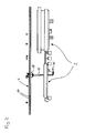
- Fig. 1 schematically shows the overall view of a food processing plant in the form of a bottler 2, on which the inventive Cleaning system is attached.
- the cleaning system according to the invention has a guideway 4, which is arranged above the filler 2 and this bypasses on its outer contour.
- the guideway 4 forms approximately an oval, wherein additionally in the middle of a central web 6 and on one side of a tangential branch 8 are provided.
- the Mitteilsteg is connected to the surrounding oval via a turntable 10.
- the tangential branch 8 is connected to the oval via a switch 12.
- the guideway 4 itself is formed from two superposed, parallel to each other extending tubes 14.
- a robot arm 16 is movable.
- the robot arm 16 is mounted on the guideway 4 with its base 18, which forms a moving unit.
- rollers 20 and 22 are arranged at the base of the robot arm 16.
- the drive roller 22 is driven by an electric motor 24.
- the rollers 20 and 22 lie open on one side of the base 18 and engage around the top and bottom of the pair of guide tubes 14 of the track 4.
- the lateral open arrangement has the advantage that the rollers 20, 22 are easy to clean.
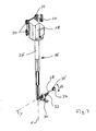
- a first leg 26 of the robot arm extends vertically downwards.
- the first leg 26 is formed in the example shown here three times telescopic. Extending the telescope is done by the weight. The retraction by a arranged in the interior of the leg 26 pull rope, which can be rolled up by an electric motor in the base 18.
- a second leg 28 is attached to this.
- the second leg 28 is pivotable about a pivot drive 30 in the direction of the arrow A, that is, it pivots about a pivot axis which extends normal to the longitudinal axis X of the first leg 28, wherein the longitudinal axis X and the longitudinal axis Y of the second leg 28 extend in a plane.
- a rotary drive 32 is also provided, via which the second leg 28 is rotatable about its longitudinal axis Y.
- the leg 26 is also rotatable about its longitudinal axis X via a rotary drive arranged in the base 18.
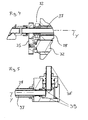
- the second leg 28 carries at its free end a tool holder 34, in which a nozzle 36 is received.
- the nozzle 36 extends in a direction perpendicular to the longitudinal axis Y of the second leg 28.
- the nozzle 36 is rotatable about a further rotary drive 32 about its own axis.
- a rotatable tube 37 is arranged in the interior of the second leg 28, which rotatably drives the nozzle assembly 36 at its front end via a bevel gear 39.
- the first leg 26 facing the end near the pivot drive 30 of the rotary drive 32 is arranged for this inner tube 37, which rotatably drives the tube 37 via a gear pair 35.
- This inner tube 37 serves at the same time the supply of detergent to the nozzle in the nozzle 36.
- the detergent is for this purpose at the rear, d. H. the first leg 26 facing end in the second leg 28 and the inner tube 37 is fed.
- the detergent is supplied via a spiral hose, not shown here. Alternatively, it would also be conceivable to move the cleaning agent into the interior of the first leg 26.
- the entire robot arm 16 is enveloped by a protective sheath, which is not shown here.
- This protective film of plastic film or fabric protects the robot arm from contamination and ensures that the robot arm 16 can be kept in a hygienically perfect condition.
- the robot arm 16 is moved along the guideway 4 so that it can bring the nozzle of the nozzle assembly 36 relative to the filling unit 2 by extending the telescope of the first leg 26 and moving the second leg 28 about the different axes in that the required areas or points of the installation 2, which require cleaning, can be accurately cleaned by spraying them with cleaning or disinfecting agent.
- the robot arm 16 can successively approach the points to be cleaned in the system 2 along the guide track 4.
- the supply of energy and cleaning agent to the robot arm 16 takes place via cables or lines from a central point in the interior of the guideway 4 spanned oval. These lines are not shown in the figures. Also, a data communication to the robot arm 16 can take place via corresponding lines, but also wirelessly.
- the robot arm 16 In order to drive on the central web, the robot arm 16 is moved onto the turntable 10. This is then rotated by 90 °, wherein a part of the guideway 4, on which the robot arm 16 is located at this moment, is also rotated by 90 ° so that it extends in the direction of the central web and the robot arm can then drive onto it ,
- the branch 8 leads to a maintenance and cleaning station for the robot arm 16 (not shown here).
- the robot arm 16 can be moved in order to clean it.
- the cleaning station permanently installed cleaning nozzles can be arranged, which spray or rinse the robot arm 16.
- the electrical power supply can also take place via the docking station 38.
- a battery may be provided in the base to provide power to the electric drive during the process. At the docking station, the battery can then be recharged.
- sensors can also be arranged on the robot arm 16.
- these sensors may be provided interchangeably with the nozzle 36, so that the tool holder 36 can be replaced by a sensor by a tool change.
- the sensor can z. B. be used to drive 16 with the help of the robot arm 16 specific points or points in the bottling plant 2 and there a bio-monitoring by reading or scanning make of indicator elements. In this way, the robot arm can be used even if it is not used for cleaning purposes. It can be provided without additional facilities, an automatic bio-monitoring.
Abstract
Description
Die Erfindung betrifft ein Reinigungssystem für eine Lebensmittel verarbeitende Anlage, beispielsweise eine Abfüll- oder Verpackungsanlage für Lebensmittel, sowie ein zugehöriges Reinigungsverfahren.The invention relates to a cleaning system for a food processing plant, such as a filling or packaging plant for food, and an associated cleaning process.
Anlagen in der Lebensmittelindustrie, sei es zur Verarbeitung von Lebensmitteln, sei es zur Abfüllung und Verpackung von Lebensmitteln müssen regelmäßig gereinigt bzw. desinfiziert werden. Dazu ist es heutzutage üblich, beispielsweise in Getränkeabfüllanlagen so genannte "cleaning in place"-Systeme zu installieren, welche die Anlagen automatisch reinigen können. Dazu ist es erforderlich, an allen zu reinigenden Anlagenteilen Sprühdüsen anzubringen, welche Reinigungs- und Desinfektionsmittel, sei es in flüssiger Form oder als Schaum oder Gel, auf die zu reinigenden Anlagenteile aufsprühen können. Diese über die gesamte Anlage verteilten Düsen erfordern eine umfangreiche Verrohrung. Bei Ausgestaltung der Anlagen ist man bestrebt, diese aus hygienischen Gründen gleich derart zu konstruieren, das möglichst wenig Stellen gegeben sind, an welchen sich Verunreinigungen anlagern können. Diesem zuwider läuft die umfangreiche Verrohrung, welche zu der Reinigungssystem selber erforderlich ist.Installations in the food industry, whether for the processing of food, whether for the filling and packaging of food, must be regularly cleaned or disinfected. For this purpose, it is customary today, for example, in beverage bottling plants to install so-called "cleaning in place" systems, which can clean the plants automatically. For this purpose, it is necessary to attach to all parts of the system to be cleaned spray nozzles, which cleaning and disinfecting agents, whether in liquid form or as a foam or gel, can spray on the system parts to be cleaned. These nozzles distributed throughout the plant require extensive piping. In the design of the plants, it is endeavored to construct them for hygienic reasons the same way, the least possible places are given, to which impurities can accumulate. This runs counter to the extensive piping, which is required for the cleaning system itself.
Im Hinblick auf diese Problematik ist es Aufgabe der Erfindung, ein verbessertes Reinigungssystem bzw. ein Reinigungsverfahren für Lebensmittel verarbeitende Anlagen bereitzustellen, welche sich einfacher und mit geringerer Beeinträchtigung des hygienischen Maschinendesigns in die Anlage integrieren lassen.In view of this problem, it is an object of the invention to provide an improved cleaning system or a cleaning method for food processing plants, which can be integrated into the plant easier and with less impairment of the hygienic machine design.
Diese Aufgabe wird gelöst durch ein Reinigungssystem mit den in Anspruch 1 angegebenen Merkmalen sowie durch ein Reinigungsverfahren mit den im Anspruch 21 angegebenen Merkmalen. Bevorzugte Ausführungsformen ergeben sich aus den zugehörigen Unteransprüchen, der nachfolgenden Beschreibung und den beigefügten Figuren.This object is achieved by a cleaning system having the features specified in claim 1 and by a cleaning method with the features specified in claim 21. Preferred embodiments will become apparent from the appended subclaims, the following description and the attached figures.
Die erfindungswesentliche Idee liegt darin, zur Reinigung der Anlage nicht mehr eine Vielzahl von fest installierten Düsen an allen zu reinigenden Stellen vorzusehen, sondern stattdessen eine geringer Anzahl von beweglichen Düsen einzusetzen, welche gezielt an die zu reinigenden Stellen der Anlage verfahren werden können. Dazu ist es vorgesehen, eine Führungsbahn anzuordnen, an welcher ein Roboterarm verfahrbar gelagert ist. Die Führungsbahn bildet somit eine Schiene, an der der Roboterarm entlang bewegt werden kann. Der Roboterarm selber trägt an seinem freien beweglichen Ende zumindest eine Düse zum Ausbringen eines Reinigungsmittels. Dieses kann ein Reinigungs- oder Desinfektionsmittel, sei es in flüssiger Form oder als Schaum, Gel, Wasser oder Dampf, oder ein sonstiges zur Reinigung der Anlage erforderliches Medium sein. Der Roboterarm selber ermöglicht eine Beweglichkeit der Düse relativ zu dem Anlenkungspunkt an der Führungsbahn, so dass der Roboter der Bewegung der Düse noch zusätzliche Freiheitsgrade über die Beweglichkeit entlang der Führungsbahn hinaus ermöglicht. Die Anzahl der Freiheitsgrade des Roboterarms und dessen genaue geometrische Gestaltung sowie die genaue Anordnung der Führungsbahn ist so gewählt, das durch Verfahren und Bewegen des Roboterarms die zumindest eine Düse an alle Stellen in der Anlage, welche zu reinigen sind, bewegt werden kann, um dort dann punktgenau das Reinigungsmittel auszubringen.The idea essential to the invention is to provide for cleaning the system no longer a variety of fixed nozzles at all points to be cleaned, but instead to use a smaller number of moving nozzles, which can be specifically moved to the points to be cleaned in the system. For this purpose, it is provided to arrange a guideway on which a robot arm is movably mounted. The guideway thus forms a rail on which the robot arm can be moved along. The robot arm itself carries at its free movable end at least one nozzle for dispensing a cleaning agent. This may be a cleaning or disinfecting agent, whether in liquid form or as a foam, gel, water or steam, or other medium required to clean the equipment. The robot arm itself allows for movement of the nozzle relative to the articulation point on the guideway, so that the robot allows the movement of the nozzle still additional degrees of freedom on the mobility along the guideway. The number of degrees of freedom of the robot arm and its exact geometric design as well as the exact arrangement of the guideway is chosen so that by moving and moving the robot arm the at least one nozzle can be moved to all points in the system which are to be cleaned then apply the cleaning agent with pinpoint accuracy.
Durch diese erfindungsgemäße Ausgestaltung wird die gesamte feste Verrohrung für ein Reinigungs- oder Desinfektionssystem an der Anlage überflüssig. Dies vereinfacht den Anlagenaufbau erheblich und verbessert das hygienische Design der Anlage, da durch das Reinigungssystem keine zusätzlichen Stellen, an denen sich Verunreinigungen anlagern könnten, geschaffen werden. Darüber hinaus ermöglicht das erfindungsgemäße System eine sehr flexible Anlagenreinigung, da durch einfache Änderung der Steuerung des Verfahr- und Bewegungssystems des Roboters der Reinigungsprozess verändert und unterschiedlichen Anforderungen angepasst werden kann. So können Sprühwinkel der Düse und ähnliches leicht verändert werden, um Reinigungsfunktionen optimal anpassen zu können, ohne Umbaumaßnahmen an der Anlage vornehmen zu müssen.By this embodiment of the invention, the entire solid piping for a cleaning or disinfection system on the system is unnecessary. This considerably simplifies and improves the system design The hygienic design of the system, as the cleaning system does not create any additional points where impurities may accumulate. In addition, the system according to the invention allows a very flexible system cleaning, since the cleaning process can be changed and adapted to different requirements by simply changing the control of the movement and movement system of the robot. Thus, spray angles of the nozzle and the like can be easily changed in order to optimally adapt cleaning functions without having to carry out conversions on the system.
Der Roboterarm weist bevorzugt zumindest zwei und weiter bevorzugt sechs Freiheitsgrade für die Bewegung der Düse auf. Es handelt sich dabei um Freiheitsgrade bezogen auf den Anlenkpunkt an der Führungsbahn. Die Beweglichkeit entlang der Führungsbahn bildet dann einen zusätzlichen Freiheitsgrad. Der Roboterarm kann als Knickarmroboter, ähnlich einem üblichen Industrieroboter ausgebildet sein. Allerdings können auch andere Roboterarme zum Einsatz kommen. Beispielsweise kann es sich auch um einen Pendelarm- oder Zylinderkoordinatenroboter handeln. Auch ein Portalsystem wäre denkbar. Die Zahl der erforderlichen Freiheitsgrade und das genaue Konstruktionsprinzip hängt maßgeblich vom Aufbau der zu reinigenden Anlage ab. Der Roboterarm und die Führungsbahn müssen so angeordnet sein, dass alle zu reinigende Punkte angefahren werden können. Die Düse ist vorzugsweise am freien äußeren Ende des Roboters angeordnet, so dass sie eine größtmögliche Beweglichkeit aufweist.The robot arm preferably has at least two and more preferably six degrees of freedom for the movement of the nozzle. These are degrees of freedom relative to the articulation point on the guideway. The mobility along the guideway then forms an additional degree of freedom. The robot arm can be designed as an articulated robot, similar to a conventional industrial robot. However, other robot arms can also be used. For example, it may also be a pendulum or cylindrical robot. Also a portal system would be conceivable. The number of required degrees of freedom and the precise design principle depends largely on the structure of the system to be cleaned. The robot arm and guideway must be arranged so that all points to be cleaned can be approached. The nozzle is preferably located at the free outer end of the robot so that it has the greatest possible mobility.
Zweckmäßigerweise ist die Führungsbahn oberhalb der zu reinigenden Anlage angebracht und der Roboter hängend an der Führungsbahn geführt. Dieser Aufbau beeinträchtigt die zu reinigende Anlage relativ wenig. Darüber hinaus wird die Zugängigkeit der Anlage von allen Seiten durch das Reinigungssystem nicht eingeschränkt. Auch können die Führungsbahn selber und der Roboterarm weniger verschmutzen. Allerdings wäre es grundsätzlich auch möglich, die Vorführungsbahn seitlich oder unterhalb der zu reinigenden Anlage anzuordnen und den Roboter gegebenenfalls entsprechend stehend oder seitlich hängend an der Führungsbahn zu führen. Auch ist es denkbar, dass die Führungsbahn in ihrem Verlauf ihre relative vertikale Position zu der Anlage ändert, d. h. in einigen Bereichen der Anlage seitlich oder unterhalb und in anderen Anlagenbereichen oberhalb der Anlage geführt ist.Conveniently, the guideway is mounted above the system to be cleaned and the robot guided hanging on the guideway. This structure affects the system to be cleaned relatively little. In addition, the accessibility of the system is not restricted by the cleaning system on all sides. Also, the The guideway itself and the robotic arm are less polluted. However, in principle it would also be possible to arrange the demonstration track laterally or below the installation to be cleaned and, if appropriate, to guide the robot to the guide track in a standing or laterally suspended manner. It is also conceivable that the guideway changes in its course their relative vertical position to the system, that is guided in some areas of the system laterally or below and in other areas above the system.
Die Führungsbahn verläuft bevorzugt zumindest entlang der Außenkontur der Anlage, insbesondere entlang der gesamten Außenkontur der Anlage, so dass der Roboterarm und die Düse von allen Seiten an die Anlage heranbewegt werden können.The guide track preferably runs at least along the outer contour of the installation, in particular along the entire outer contour of the installation, so that the robot arm and the nozzle can be moved up to the installation from all sides.
Das erfindungsgemäße System ist nicht auf die Reinigung einer einzelnen Anlage beschränkt, vielmehr ist es auch möglich, die Führungsbahn entlang mehrerer zu reinigenden Anlagen anzuordnen. Dies können miteinander im Zusammenhang stehenden Anlagen, aber auch voneinander unabhängige Anlagen sein, welche durch ein und denselben Reinigungsroboter gereinigt werden. So ist es beispielsweise möglich, in einem Abfüllbetrieb mit mehreren Abfüllstraßen, einen einzigen Reinigungsroboter vorzusehen, welcher die Straßen abwechselnd reinigt, während die anderen Abfüllanlagen im normalen Betrieb sind. Der Roboterarm wird dazu lediglich entlang der Führungsbahn zu der grade zu reinigenden Anlage verfahren. Das erfindungsgemäße Reinigungssystem ist dabei nicht auf die Reinigung von Anlagen beschränkt, vielmehr können auch weitere Gegenstände oder der Raum, in welchem sich das Reinigungssystem befindet, gereinigt werden. Die Führungsbahn muss lediglich entsprechend angeordnet werden, dass der Roboterarm alle zu reinigenden Bereiche erreichen kann. Auf diese Weise können die Investitionskosten verringert werden, da die Zahl der erforderlichen Roboterarme reduziert wird. Dabei ist zu verstehen, dass das erfindungsgemäße System nicht auf die Anordnung eines Roboterarmes beschränkt ist, es ist auch denkbar in dem System mehrere Roboterarme vorzusehen, um die Reinigung schneller durchführen zu können.The system according to the invention is not limited to the cleaning of a single plant, but rather it is also possible to arrange the guideway along several plants to be cleaned. These may be related systems, but also independent of each other plants, which are cleaned by one and the same cleaning robot. For example, in a bottling plant having multiple bottling lines, it is possible to provide a single cleaning robot that alternately cleans the streets while the other bottling plants are in normal operation. The robot arm is only moved along the guideway to the just to be cleaned plant. The cleaning system according to the invention is not limited to the cleaning of facilities, but also other objects or the room in which the cleaning system is located, be cleaned. The guideway only needs to be arranged appropriately so that the robotic arm can reach all the areas to be cleaned. In this way, the investment costs can be reduced because the number of required robot arms is reduced. It should be understood that the system according to the invention is not limited to the arrangement of a robot arm, it is also conceivable to provide a plurality of robot arms in the system in order to carry out the cleaning faster.
In komplexeren Systemen wird es erforderlich sein, die Führungsbahn mit Abzweigungen zu versehen. So kann in der Führungsbahn zumindest eine Verzweigung vorhanden sein, wobei am Abzweigpunkt eine Weiche oder ein Drehteller zu Richtungsänderung angeordnet ist. Bei dem Drehteller kann der Roboterarm auf der Stelle gedreht werden. So können sehr kleine Abbiegeradien erreicht werden. Auf dem Drehteller wird ein Stück der Führungsbahn mit dem an dieser Stelle positionierten Roboterarm auf der Stelle gedreht. Insgesamt kann die Führungsbahn modular aufgebaut sein. Das heißt, es können Standardabschnitte mit Geraden oder Radien vorgesehen sein, welche je nach Einsatzort entsprechend miteinander kombiniert werden können, um eine für die zugehörige Anlage passende Führungsbahn auszubilden. Alternativ können auch individuelle Teilstücke mit speziellen Formen oder Krümmungsradien gefertigt werden. Der modulare Aufbau hat jedoch den Vorteil, dass die Zahl der zu fertigenden Einzelteile für die Führungsbahn auf wenige Standardteile reduziert werden kann.In more complex systems, it will be necessary to provide the guideway with branches. Thus, at least one branch may be present in the guideway, wherein at the branch point a switch or a turntable is arranged to change direction. In the turntable, the robot arm can be rotated on the spot. So very small turning radii can be achieved. On the turntable a piece of the guideway is rotated with the robot arm positioned at this point on the spot. Overall, the guideway can be modular. This means that standard sections with straight lines or radii can be provided which, depending on the place of use, can be combined with one another in order to form a suitable guideway for the associated installation. Alternatively, individual sections with special shapes or radii of curvature can be made. However, the modular structure has the advantage that the number of items to be manufactured for the guideway can be reduced to a few standard parts.
Gemäß einer weiteren bevorzugten Ausführungsform ist in dem System eine Reinigungsstation vorgesehen, zu welcher die Führungsbahn führt und an welcher Reinigungsdüsen zur Außenreinigung des Roboterarmes angeordnet sind. Dies ermöglicht es, den Roboterarm entlang der Führungsbahn in die Reinigungsstation zu verfahren und dort mit den fest installierten Reinigungsdüsen mit geeigneten Reinigungs- und Desinfektionsmedien von außen zu reinigen. Der Roboterarm selber ist vorzugsweise mit einem Schutzmantel bzw. Schutzanzug, beispielsweise aus einer dichten Kunststofffolie versehen, so dass zum einen eine Verunreinigung der mechanischen Teile des Roboterarmes verhindert wird und zum anderen verhindert wird, dass vom Roboterarm Verunreinigungen in die Anlage gelangen können. Ein solcher Schutzanzug ist besonders günstig durch Absprühen zu reinigen.According to a further preferred embodiment, a cleaning station is provided in the system, to which the guideway leads and at which cleaning nozzles for external cleaning of the robot arm are arranged. This makes it possible to move the robot arm along the guideway into the cleaning station and clean it there with the fixed cleaning nozzles with suitable cleaning and disinfection media from the outside. The robot arm itself is preferably provided with a protective casing or protective suit, for example made of a dense plastic film, so that on the one hand contamination of the mechanical parts of the robot arm is prevented and on the other hand, it is prevented that impurities can enter the system from the robot arm. Such a protective suit is particularly favorable to clean by spraying.
Die Führungsbahn ist vorzugsweise aus zumindest einem Rundprofil, weiter bevorzugt aus zwei parallel zueinander verlaufenden Rundprofilen gebildet. Derartige Rundprofile, beispielsweise aus rostfreiem Stahl, sind als Standardteile wie Rohre oder Vollmaterial verfügbar. Darüber hinaus lassen sie sich leicht in gewünschte Radien biegen und weisen eine glatte gut zu reinigende Oberfläche auf, an welcher sich Verunreinigungen nur schlecht anlagern können. Bevorzugt ist die Schiene bzw. Führungsbahn aus zwei parallel zueinander angeordneten Rundprofilen bzw. Rohren gebildet. Eine solche Anordnung ermöglicht eine bessere Führung des Roboterarmes, da ein Pendeln oder Drehen um die Längsachse der Führungsbahn verhindert werden kann. Die beiden Rundprofile sind vorzugsweise über Querstege fest miteinander verbunden. Die Querstege sind weiter bevorzugt in regelmäßigen Abständen zueinander angeordnet, so dass sie gleichzeitig der Weg- bzw. Positionserfassung beim Verfahren des Roboters entlang der Führungsbahn dienen können, da durch ein geeignetes Erfassungssystem einfach die Zahl der passierten Stege gezählt werden kann, um so eine zurückgelegte Wegstrecke und damit die Position des Roboterarmes zu ermitteln. Zusätzlich oder alternativ kann die Positionserfassung auch über andere Wegmess- bzw. Aufnahmesysteme erfolgen, beispielsweise können auch die Umdrehungen eines auf der Führungsbahn abrollenden Antriebs- oder Führungsrades zur Wegerfassung gezählt werden.The guideway is preferably formed of at least one round profile, more preferably of two mutually parallel round profiles. Such round profiles, for example made of stainless steel, are available as standard parts such as pipes or solid material. In addition, they can be easily bent into desired radii and have a smooth surface to clean, on which impurities can accumulate only bad. Preferably, the rail or guide track is formed from two mutually parallel round profiles or tubes. Such an arrangement allows a better guidance of the robot arm, since a pendulum or rotation about the longitudinal axis of the guideway can be prevented. The two round profiles are preferably firmly connected to each other via transverse webs. The transverse webs are further preferably arranged at regular intervals to each other, so that they can simultaneously serve the position or position detection when moving the robot along the guideway, as can be counted by a suitable detection system simply the number of passages webs, so as a traversed Distance and thus determine the position of the robot arm. Additionally or alternatively, the position detection can also take place via other displacement measuring or recording systems, for example, the revolutions of a rolling on the guideway drive or guide wheel can be counted for path detection.
Weiter bevorzugt ist im Inneren der Führungsbahn eine Fluidleitung zur Zufuhr des Reinigungsmittels ausgebildet. Dies ist besonders günstig dann möglich, wenn die Führungsbahn zumindest ein rohrförmiges Profil aufweist, da dieses Rohr dann in seinem Inneren gleichzeitig das Reinigungsmedium führen kann. Auf diese Weise wird die Zahl der Einzelteile und der Materialaufwand reduziert.More preferably, a fluid conduit for supplying the cleaning agent is formed in the interior of the guideway. This is particularly favorable then possible if the guideway has at least one tubular profile, since this tube then in its interior at the same time the cleaning medium can lead. In this way, the number of items and the cost of materials is reduced.
In einer weiteren bevorzugten Ausführungsform erfolgt die Reinigungsmittelzufuhr zu dem Roboterarm über eine Schlauchleitung welche den Roboterarm mit einem zentralen Anschluss für die Zufuhr des Reinigungsmittels verbindet. So kann beispielsweise bei einer ringförmigen Kontur der Führungsbahn der zentrale Anschluss im Wesentlichen in der Mitte der Bahn angeordnet sein und der Schlauch erstreckt sich von dort in etwa radial zu dem Roboterarm an der Führungsbahn. Bei Bewegung des Roboterarmes dreht sich der Schlauch dann um den zentralen Anschluss. In diesem ist vorzugsweise ein drehender Anschluss bzw. Drehkupplung vorgesehen, so dass die Bewegung des Roboterarmes entlang der Führungsbahn durch diese Schlauchzufuhr nicht eingeschränkt wird. Auch die elektrische Energieversorgung eines Antriebes an dem Roboterarm kann über ein entsprechendes Kabel, welches sich ähnlich zu der Schlauchleitung erstreckt, erfolgen. Auch Daten bzw. Steuerleitungen können so verlegt sein. Daten- bzw. Steuersignale könnten jedoch auch drahtlos per Funk übertragen werden. Die elektrische Energieversorgung könnte darüber hinaus auch über Stromschienen entlang der Führungsbahn realisiert werden.In a further preferred embodiment, the supply of cleaning agent to the robot arm takes place via a hose line which connects the robot arm to a central connection for the supply of the cleaning agent. Thus, for example, in the case of an annular contour of the guide track, the central connection can be arranged essentially in the middle of the track and the tube extends from there approximately radially to the robot arm on the guide track. When moving the robot arm, the hose then rotates around the central port. In this, a rotating connection or rotary coupling is preferably provided, so that the movement of the robot arm along the guide path is not restricted by this hose supply. Also, the electrical power supply of a drive to the robot arm can via a corresponding cable, which extends similar to the hose, done. Also data or control lines can be so misplaced. However, data or control signals could also be transmitted wirelessly by radio. The electrical energy supply could also be realized via busbars along the guideway.
Gemäß einer weiteren bevorzugten Ausführungsform der Erfindung ist an der Führungsbahn eine Docking-Station angeordnet, welche Anschlusskupplungen für zumindest eine Fluidleitung und vorzugsweise zumindest einen elektrischen Anschluss aufweist, wobei der Roboterarm korrespondierende Anschlusskupplungen aufweist, welche bei Erreichen der Docking-Station mit den Anschlusskupplungen der Docking-Station in Eingriff treten können. Die korrespondieren Anschlusskupplungen des Roboterarmes sind vorzugsweise an oder in der Basis des Roboterarmes, welche verfahrbar an der Führungsbahn geführt ist, angeordnet. Die Docking-Station und die korrespondierenden Anschlusskupplungen ermöglichen es, wenn der Roboterarm die Position der Docking-Station an der Führungsbahn erreicht, dass der Roboterarm mit seinen Anschlusskupplungen an die Anschlusskupplungen der Docking-Station andocken kann, so dass dort eine Verbindung der Fluidleitung zwischen der Docking-Station und dem Roboterarm und gegebenenfalls auch elektrische Verbindungen hergestellt werden. Auf diese Weise kann die Zufuhr des Reinigungsmittels durch die Fluidleitung von der Docking-Station in den Roboterarm erfolgen. So kann auf die Zuführung mittels einer Schlauchleitung zu einem zentralen Punkt verzichtet werden. Stattdessen werden dann bevorzugt an allen Punkten der Führungsbahn, an welchen Reinigungsaufgaben durch den Roboterarm durchzuführen sind, entsprechende Docking-Stationen angeordnet, um die Zufuhr von Reinigungsmittel zu dem Roboterarm an diesen Stellen zu gewährleisten. Der Roboterarm fährt dann von Docking-Station zu Docking-Station, um dort dann jeweils anzudocken und einen Reinigungsvorgang an einem speziellen Punkt bzw. Bereich der Anlage durchzuführen. Die Stromversorgung des Roboterarmes kann ebenfalls über die Docking-Station oder, wie oben beschrieben, beispielsweise über Stromschienen entlang der Führungsbahn erfolgen. Wenn die Stromversorgung über die Docking-Station erfolgt, kann es zweckmäßig sein, den Roboterarm mit einem Energiespeicher, beispielsweise einem Akku zu versehen, der es dem Roboterarm ermöglicht, durch eigenen Antrieb von einer Docking-Station zur nächsten zu verfahren. Der Signalübertragung für Sensor- bzw. Steuersignalen erfolgt in diesem Fall vorzugsweise über Funk, könnte jedoch auch über elektrische Kontakte an der Docking-Station realisiert werden.According to a further preferred embodiment of the invention, a docking station is arranged on the guideway, which has connection couplings for at least one fluid line and preferably at least one electrical connection, wherein the robotic arm has corresponding connection couplings which upon reaching the docking station with the connection couplings of the docking Station can intervene. The corresponding connection couplings of the robot arm are preferably arranged on or in the base of the robot arm, which is movably guided on the guide track. The docking station and the corresponding connection couplings allow when the robotic arm reaches the position of the docking station on the guideway that the robotic arm can dock with its couplings to the docking terminals of the docking station, so there is a connection of the fluid line between the docking station and the robot arm and, where appropriate also electrical connections are made. In this way, the supply of the cleaning agent through the fluid line from the docking station in the robot arm can be done. So can be dispensed with the supply by means of a hose to a central point. Instead, corresponding docking stations are then preferably arranged at all points of the guideway on which cleaning tasks are to be performed by the robot arm in order to ensure the supply of cleaning agent to the robot arm at these locations. The robot arm then moves from docking station to docking station, where it then docked and perform a cleaning process at a specific point or area of the system. The power supply of the robot arm can also be done via the docking station or, as described above, for example, via busbars along the guideway. When power is supplied through the docking station, it may be convenient to provide the robotic arm with an energy storage, such as a rechargeable battery, that allows the robotic arm to travel from one docking station to the next by its own drive. The signal transmission for sensor or control signals is in this case preferably via radio, but could also be realized via electrical contacts on the docking station.
Auch ist es möglich, die Reinigungsmittelzufuhr und die elektrischen Anschlüsse des Roboterarmes in einer Kombination einer zentralen Zuführung und einer Art Docking-Station zu reduzieren. Wenn die Führungsbahn so ausgestaltet ist, das mit einem Roboterarm mehrere Anlagen beispielsweise in einer großen Halle gereinigt werden können, ist es denkbar, das im Bereich jeder Anlage eine Docking-Station vorgesehen ist, an welcher der Roboter dann ankoppelt, wobei diese Docking-Station gemeinsam mit dem Roboter über einen bestimmten Bereich der Führungsbahn bewegbar ist, in welchem dann die Reinigungsmittelzufuhr und gegebenenfalls die elektrische Energieversorgung über Schlauchleitungen bzw. Kabel von einem zentralen Punkt aus erfolgen. Wenn der Roboter dann zur nächsten Anlage weiter fährt, koppelt er von der Docking-Station ab, fährt zu der nächsten Anlage und koppelt dort dann wieder an eine entsprechende Docking-Station an. Auf diese Weise können auch sehr große Anlagen problemlos durch einen oder wenige Roboterarme in der vorangehend beschriebenen Ausgestaltung gereinigt werden. Die einzelnen Anlagen bzw. Anlagenteile müssen nur über entsprechende Führungsbahnen miteinander verbunden sein, so dass der Roboterarm zwischen den einzelnen Anlagen verfahren kann.It is also possible to reduce the detergent supply and the electrical connections of the robot arm in a combination of a central feeder and a kind of docking station. If the guideway is designed so that it can be cleaned with a robot arm several systems, for example in a large hall, it is It is conceivable that a docking station is provided in the area of each installation, to which the robot then attaches, wherein this docking station is movable together with the robot over a certain area of the guideway, in which then the detergent supply and optionally the electrical energy supply via Hose lines or cables are made from a central point. If the robot then continues to the next system, it disconnects from the docking station, drives to the next system and then reconnects there to a corresponding docking station. In this way even very large plants can be easily cleaned by one or a few robot arms in the embodiment described above. The individual plants or plant components must be connected to each other only via corresponding guideways, so that the robot arm can move between the individual plants.
Bevorzugt weist der Roboterarm eine Verfahreinheit auf, welche an der Führungsbahn geführt ist und einem Antrieb zum Verfahren des Roboterarmes entlang der Führungsbahn hat. Die Verfahreinheit bildet die Basis des Roboterarmes, welche den Roboterarm an der Führungsbahn hält. Die Verfahreinheit weist vorzugsweise mehrere Führungs- bzw. Antriebsrollen auf, wobei es ausreicht, eine Rolle anzutreiben. Bevorzugt rollt die Antriebsrolle reibschlüssig auf der Führungsbahn ab. Es ist jedoch auch denkbar, eine Verzahlung vorzusehen, über welche ein Antriebsritzel mit der Führungsbahn formschlüssig in Eingriff tritt. Vorzugsweise ist ein elektrischer Antriebsmotor in der Verfahreinheit angeordnet, welcher eine oder mehrere Antriebsrollen antreibt.Preferably, the robot arm has a moving unit, which is guided on the guide track and has a drive for moving the robot arm along the guide track. The trajectory forms the base of the robot arm, which holds the robot arm on the guideway. The track unit preferably has a plurality of guide or drive rollers, it being sufficient to drive a roller. Preferably, the drive roller rolls frictionally on the guideway. However, it is also conceivable to provide a payment, via which a drive pinion engages positively with the guide track. Preferably, an electric drive motor is arranged in the moving unit, which drives one or more drive rollers.
Der Roboterarm selber ist bevorzugt aus zwei Schenkeln gebildet, wobei sich ein erster Schenkel ausgehend von der Führungsbahn erstreckt und der zweite Schenkel an dem der Führungsbahn abgewandten Ende des ersten Schenkels vorzugsweise schwenkbar angelenkt ist. Der erste Schenkel erstreckt sich im Falle einer oben angeordneten Führungsbahn vorzugsweise senkrecht von der Führungsbahn nach unten und der zweite Schenkel erstreck sich quer zu dieser Richtung, wobei er vorzugsweise um 180° relativ zu der Längsachse des ersten Schenkels verschwenkbar ist. Das heißt, der Schenkel kann senkrecht nach oben klappen und über eine Ausrichtung von 90° zu dem ersten Schenkel bis in eine Lage, in welcher er im Wesentlichen nach unten weist, verschwenkt werden. Es muss jedoch kein Verschwenkbereich um wirklich 180° vorgesehen sein, es ist auch ein kleinerer Verschwenkbereich denkbar, wobei die Verschwenkbewegung vorzugsweise in einer Ebene erfolgt, welche sich parallel zur Längsachse des ersten Schenkels erstreckt.The robot arm itself is preferably formed from two legs, wherein a first leg extends from the guide track and the second leg is preferably pivotally connected to the end of the first leg remote from the guide track. Of the In the case of an overhead guide track, the first leg preferably extends vertically downwards from the guide track and the second leg extends transversely to this direction, wherein it preferably is pivotable by 180 ° relative to the longitudinal axis of the first leg. That is, the leg can fold upwards vertically and be pivoted about an orientation of 90 ° to the first leg to a position in which it points substantially downwards. However, there must be no pivoting range is provided by 180 °, it is also conceivable a smaller pivoting range, wherein the pivoting movement preferably takes place in a plane which extends parallel to the longitudinal axis of the first leg.
Der erste Schenkel, welcher sich bevorzugt in vertikaler Richtung erstreckt, ist weiter bevorzugt teleskopierbar ausgebildet, so dass der vertikale Abstand der Düse zu der Führungsbahn durch Ein- und Ausfahren des senkrechten Schenkels verändert werden kann. Auch der zweite Schenkel kann teleskopierbar ausgebildet sein.The first leg, which preferably extends in the vertical direction, is furthermore preferably telescopic, so that the vertical distance of the nozzle from the guide track can be changed by extending and retracting the vertical leg. Also, the second leg may be formed telescopic.
Weiter bevorzugt ist zumindest einer der Schenkel um seine Achse drehbar. Besonders bevorzugt sind beide Schenkel um ihre Achse drehbar.More preferably, at least one of the legs is rotatable about its axis. Particularly preferably, both legs are rotatable about their axis.
Der zweite Schenkel trägt an seinem freien, dem ersten Schenkel abgewandten Ende bevorzugt einen Düsenstock mit der Düse. Dabei ist der Düsenstock weiter bevorzugt drehbar angeordnet. Besonders bevorzugt erstreckt sich der Düsenstock am Ende des zweiten Schenkels senkrecht zu diesem und ist um seine Längsachse drehbar. Die eigentliche Düse ist dabei vorzugsweise in einer Richtung parallel zu dem zweiten Schenkel gerichtet, so dass die Abstrahlrichtung der Düse durch Drehen des Düsenstocks um 360° gedreht werden kann.The second leg preferably carries at its free, the first leg end remote from a nozzle with the nozzle. In this case, the nozzle assembly is further preferably rotatably arranged. Particularly preferably, the nozzle extends at the end of the second leg perpendicular to this and is rotatable about its longitudinal axis. The actual nozzle is preferably directed in a direction parallel to the second leg, so that the emission direction of the nozzle can be rotated by rotating the nozzle block by 360 °.
Die Reinigungsmittelzufuhr im Roboterarm erfolgt entweder durch eine außen am Roboter verlegte Schlauchleitung, wobei diese dann vorzugsweise innerhalb eines Schutzanzuges des Roboters, sofern dieser vorgesehen ist, angeordnet wird. Alternativ ist es auch möglich die Reinigungsmittelzufuhr durch das Innere des Roboterarmes verlaufen zu lassen. Auch Kombinationen beider Systeme sind möglich. So ist es besonders bevorzugt, das entlang des ersten teleskopierbaren Schenkels die Reinigungsmittelzufuhr durch einen Spiralschlauch erfolgt, wobei dieser Spiralschlauch dann in den zweiten Schenkel mündet. Diese Mündung ist vorzugsweise in einem Abschnitt des zweiten Schenkels, welcher dem ersten Schenkel zugewandt ist, angeordnet. Die weitere Reinigungsmittelzufuhr zu der Düse erfolgt dann durch das Innere des zweiten Schenkels, so dass dieser insgesamt relativ dünn und schlank ausgestaltet werden kann, so dass er auch in enge Freiräume in der Anlage zu deren Reinigung eindringen kann.The supply of detergent in the robot arm is carried out either by a hose line laid outside the robot, which is then preferably arranged inside a protective suit of the robot, if provided. Alternatively, it is also possible to run the detergent supply through the interior of the robot arm. Also combinations of both systems are possible. Thus, it is particularly preferred that along the first telescoping leg, the detergent is supplied through a spiral tube, said spiral tube then opens into the second leg. This mouth is preferably arranged in a portion of the second leg, which faces the first leg. The further supply of detergent to the nozzle then takes place through the interior of the second leg, so that this total can be made relatively thin and slim, so that it can penetrate into tight spaces in the system for their cleaning.
Besonders bevorzugt erfolgt die Reinigungsmittelzufuhr im zweiten Schenkel durch ein im Inneren des zweiten Schenkel gelegenen Rohr. Dieses Rohr kann dann gleichzeitig dazu dienen, eine Drehbewegung auf den Düsenstock zu übertragen. So kann insgesamt eine sehr schlanke Ausgestaltung des zweiten Schenkels durch zwei konzentrisch ineinander angeordnete Rohre erreicht werden. Dabei kann sich das äußere Rohr vorzugsweise um seine Längsachse drehen, so dass die Düse bzw. der Düsenstock um die Längsachse des zweiten Schenkels gedreht werden kann. In dem Fall, das der Düsenstock sich normal zu dieser Längsachse erstreckt, ist darüber hinaus durch Drehung des inneren Rohres über ein Kegelradgetriebe auch eine Drehung des Düsenstockes um seine sich quer zur Längsachse des zweiten Schenkels erstreckende Längsachse möglich.Particularly preferably, the supply of detergent in the second leg is effected by a tube located in the interior of the second leg. This tube can then serve simultaneously to transmit a rotary motion to the nozzle. Thus, on the whole, a very slim design of the second leg can be achieved by means of two concentrically arranged tubes. In this case, the outer tube can preferably rotate about its longitudinal axis, so that the nozzle or the nozzle can be rotated about the longitudinal axis of the second leg. In the event that the nozzle extends normal to this longitudinal axis, in addition, by rotation of the inner tube via a bevel gear and a rotation of the nozzle assembly about its transverse to the longitudinal axis of the second leg extending longitudinal axis is possible.
Bei einer weiteren bevorzugten Ausführungsform weist der Roboterarm eine Werkzeugaufnahme auf, welche vorzugsweise am freien Ende des Roboterarmes angeordnet ist und in welche ein Düsenstock mit der Düse austauschbar aufgenommen ist. Dies ermöglicht einen einfachen Düsenwechsel, da die Düse aus der Werkzeugaufnahme entnommen und durch eine andere Düse ersetzt werden kann. Ein solcher Wechsel des Düsenstockes kann bevorzugt automatisch erfolgen. Dazu kann in dem Reinigungssystem eine Wechselstation vorgesehen sein, an welcher die verschiedenen Düsenstöcke bereitgehalten werden und welche zum Düsenwechsel von dem Roboterarm angefahren wird, wobei der Roboterarm dann einen Düsenstock ablegt und einen anderen Düsenstock aufnimmt. Die Werkzeugaufnahme ist dazu vorzugsweise mit einer automatischen bzw. ferngesteuert betätigbaren Kupplungsvorrichtung zum Ergreifen und Lösen der Düsenstöcke versehen.In a further preferred embodiment, the robot arm has a tool holder, which preferably at the free end of Robot arm is arranged and in which a nozzle is received replaceable with the nozzle. This allows a simple nozzle change, since the nozzle can be removed from the tool holder and replaced by another nozzle. Such a change of the nozzle assembly can preferably be done automatically. For this purpose, a change station may be provided in the cleaning system, at which the various nozzle sticks are kept ready and which is approached for nozzle change by the robot arm, wherein the robot arm then deposits a nozzle and receives another nozzle. For this purpose, the tool holder is preferably provided with an automatic or remotely operable coupling device for gripping and releasing the nozzle rods.
Weiter bevorzugt weist der Roboterarm eine Werkzeugaufnahme auf, welche zur Aufnahme von Bearbeitungs- und Handhabungswerkzeugen und/oder Sensoren ausgebildet ist. Bevorzugt ist dies dieselbe Werkzeugaufnahme, welche auch zur Aufnahme der unterschiedlichen Düsenstöcke dient. Dies ermöglicht es, dass der Roboterarm auch andere Bearbeitungs- bzw. Handhabungsaufgaben ausführen kann, so dass eine universelle Verwendung des Roboterarmes in der Anlage möglich wird. So kann der Roboterarm in einer Verpackungsanlage beispielsweise außerhalb der Reinigungsvorgänge dazu dienen, Produkte in eine Verpackung einzulegen. Auf diese Weise werden Ruhezeiten des Roboterarmes, in denen dieser ungenutzt ist, vermieden. Es ist jedoch zu verstehen, das entsprechende Handhabungs- oder Bearbeitungseinrichtungen auch fest gleichzeitig zu einem Düsenstock an dem Roboterarm angeordnet sein können, so dass ein Austausch der einzelnen Werkzeuge bzw. Düsenstöcke nicht erforderlich ist, sondern diese ständige mit dem Roboterarm mitgeführt werden.More preferably, the robot arm on a tool holder, which is designed to hold processing and handling tools and / or sensors. This is preferably the same tool holder, which also serves to accommodate the different nozzle sticks. This makes it possible for the robot arm to also perform other processing or handling tasks, so that a universal use of the robot arm in the system becomes possible. Thus, the robot arm in a packaging system, for example, outside the cleaning operations serve to insert products in a package. In this way, rest periods of the robot arm, in which it is unused, avoided. However, it is to be understood that the corresponding handling or processing means can also be fixedly arranged simultaneously with a nozzle assembly on the robot arm, so that an exchange of the individual tools or nozzle nozzles is not required, but they are constantly carried along with the robot arm.
In den Zeiten, in den der Roboter nicht zu Reinigungsaufgaben verwendet wird, kann er, wie beschrieben zu Handhabungs- oder Bearbeitungsaufgaben eingesetzt werden.In times when the robot is not used for cleaning tasks, it can be used as described for handling or machining tasks.
-Darüber hinaus ist auch ein Einsatz von Bio- Monitoring möglich. Dazu trägt der Roboterarm dann zumindest einen Sensor, welcher geeignet ist, bestimmte Kontrollpunkte an der Anlage vorzugsweise optisch abzulesen. Dieser Sensor kann fest an dem Roboterarm angebracht sein oder beispielsweise auch als austauschbares Werkzeug ausgebildet sein, welches von dem Roboterarm nur dann aufgenommen wird, wenn der Roboterarm für das Bio-Monitoring eingesetzt wird.In addition, a use of bio-monitoring is possible. For this purpose, the robot arm then carries at least one sensor which is suitable for optically reading certain control points on the system. This sensor can be fixedly attached to the robot arm or, for example, also designed as an exchangeable tool, which is picked up by the robot arm only when the robot arm is used for bio-monitoring.
Die Erfindung betrifft ferner ein Reinigungsverfahren zur Reinigung einer Lebensmittel verarbeitenden Anlage. Bei dem Reinigungsverfahren wird bevorzugt ein Reinigungssystem gemäß der vorangehenden Beschreibung eingesetzt. Daher ist zu verstehen, dass Merkmale, welche oben anhand des Reinigungssystems beschrieben worden sind, ebenfalls bei dem nachfolgend beschriebenen Reinigungsverfahrens zur Anwendung kommen können.The invention further relates to a cleaning method for cleaning a food processing plant. In the cleaning method, a cleaning system according to the preceding description is preferably used. Therefore, it should be understood that features described above with reference to the cleaning system may also be used in the cleaning process described below.
Bei dem erfindungsgemäßen Reinigungsverfahren wird eine Düse zum Ausbringen eines Reinigungsmittels mittels eines an einer Führungsbahn verfahrbaren Roboterarmes zu den zu reinigenden Punkten der Anlage bewegt. Dort wird dann aus der Düse das Reinigungsmittel auf die Anlage ausgebracht. Dies ermöglicht es, durch Verfahren und entsprechende Platzierung der Düse Anlagenteile punktgenau zu reinigen. Das heißt, es muss nicht mehr die Anlage großflächig mit Reinigungsmittel eingesprüht werden, sondern es können gezielt die verschmutzungsanfälligen Bereiche gereinigt werden. Auch können einzelne Bereiche unterschiedlich intensiv oder auch in unterschiedlichen Zeitintervallen gereinigt werden. Das erfindungsgemäße Verfahren ermöglicht hier eine sehr flexible Ausführung des Reinigungsverfahrens. So kann die Menge des erforderlichen Reinigungsmittels reduziert werden. Darüber hinaus ist keine aufwändige Installation eines Reinigungssystems innerhalb der Anlage erforderlich.In the cleaning method according to the invention, a nozzle for dispensing a cleaning agent is moved by means of a robot arm movable on a guide track to the points of the installation to be cleaned. There, the cleaning agent is then discharged from the nozzle to the plant. This makes it possible to precisely clean system parts by means of procedures and corresponding placement of the nozzle. This means that it is no longer necessary to spray the system over a large area with cleaning agents, but instead it is possible to specifically clean the areas prone to contamination. Also, individual areas can be cleaned with different intensity or at different time intervals. The method according to the invention allows a very flexible embodiment of the cleaning method. So can the crowd of the required cleaning agent can be reduced. In addition, no complex installation of a cleaning system within the system is required.
Ferner ist es bevorzugt vorgesehen, dass der Roboterarm entlang der Führungsbahn in eine Reinigungsstation verfahren wird, in welcher durch feststehende Reinigungsdüsen von außen gereinigt wird. Dies erfolgt vorzugsweise nach den von dem Roboterarm durchgeführten Reinigungsaufgaben, so dass anschließend der Roboter selber gereinigt wird und dann sauber für den nächsten Einsatz zur Verfügung steht. Es ist jedoch auch denkbar, den Roboterarm direkt vor einem Reinigungsvorgang zu reinigen, um zu verhindern, dass bei der Reinigung die Anlage durch den Roboter selbst kontaminiert wird.Furthermore, it is preferably provided that the robot arm is moved along the guideway into a cleaning station in which cleaning is carried out from outside by fixed cleaning nozzles. This is preferably done according to the cleaning tasks performed by the robot arm, so that subsequently the robot itself is cleaned and then cleanly available for the next use. However, it is also conceivable to clean the robot arm directly before a cleaning process, in order to prevent that during cleaning the system is contaminated by the robot itself.
Besonders bevorzugt ist es, dass der Roboterarm in den Zeiten in denen er keine Reinigungsaufgaben ausführt, für Handhabungs-, Bearbeitungs- oder Überwachungsaufgaben oder sonstige Aufgaben in der Anlage eingesetzt wird. So wird eine universelle Nutzung des Roboterarmes erreicht, welche Stillstandzeiten vermeidet. Beispielsweise könnte der Roboterarm eingesetzt werden, um in einer Verpackungsanlage Waren bzw. Produkte in Verpackungen einzulegen. Ferner könnten befüllte Behältnisse von einem Förderband abgenommen und auf Paletten abgesetzt werden und ähnliches. Darüber hinaus könnte der Roboterarm auch Überwachungs- und Kontrollaufgaben aufnehmen, beispielsweise über geeignete an dem Roboterarm angebrachte Sensoren ein Bio-Monitoring innerhalb der Anlage durchführen, indem im Betrieb einzelne Punkte angefahren werden und dort angebrachte Bio-Indikatoren von einem an dem Roboterarm angebrachten Sensor, beispielsweise einer Kamera gescannt bzw. ausgelesen werden.It is particularly preferred that the robot arm is used for handling, processing or monitoring tasks or other tasks in the system during the periods in which it performs no cleaning tasks. Thus, a universal use of the robot arm is achieved, which avoids downtime. For example, the robot arm could be used to place goods or products in packaging in a packaging plant. Furthermore, filled containers could be removed from a conveyor belt and placed on pallets and the like. In addition, the robotic arm could also record monitoring and control tasks, for example by means of suitable sensors mounted on the robot arm to carry out a bio-monitoring within the system by operating individual points in the device and attached there biological indicators of a mounted on the robot arm sensor, For example, a camera to be scanned or read.
Das Reinigungssystem gemäß der vorangehenden Beschreibung weist vorzugsweise eine Steuereinrichtung auf, welche den gesamten Reinigungsvorgang steuert. Diese Steuereinrichtung kann mit der üblichen Anlagen- bzw. Maschinensteuerung der zu reinigenden Anlagen verknüpft sein, so dass die Reinigungsvorgänge automatisch zu bestimmten Zeitpunkten durchgeführt werden können. Darüber hinaus kann die Maschinensteuerung dann auch zu den Zeiten, in welchen der Roboterarm nicht zur Reinigung eingesetzt wird, diesen ansteuern, um die genannten anderen Aufgaben durchzuführen.The cleaning system according to the preceding description preferably has a control device which controls the entire cleaning process controls. This control device can be linked to the usual plant or machine control of the plants to be cleaned, so that the cleaning operations can be performed automatically at certain times. Moreover, even at times when the robotic arm is not used for cleaning, the machine controller may then drive it to perform the aforementioned other tasks.
Besonders bevorzugt wird das erfindungsgemäße Reinigungssystem und Reinigungsverfahren in einer Anlage zur Verarbeitung von Lebensmitteln bzw. in einer Anlage zum Verpacken oder Abfüllen von Lebensmitteln, beispielsweise in einer Flaschenabfüllanlage eingesetzt. Anlagen mit einem solchen Reinigungssystem ist ebenfalls Gegenstand der Erfindung.The cleaning system and cleaning method according to the invention are particularly preferably used in a plant for processing food or in a plant for packaging or filling food, for example in a bottling plant. Facilities with such a cleaning system is also an object of the invention.
Nachfolgend wird die Erfindung beispielhaft anhand der beigefügten Figuren beschrieben. In diesen zeigt:
- Fig. 1
- eine schematische perspektivische Gesamtansicht einer Abfüll- anlage mit dem erfindungsgemäßen Reinigungssystem,
- Fig. 2
- eine Seitenansicht der Anlage gemäß
Fig. 1 , - Fig. 3
- eine perspektivische Ansicht des Roboterarms;
- Fig. 4.
- eine Schnittansicht des hinteren, einem ersten Schenkel zuge- wandten Endes eines zweiten Schenkels des Roboterarms, und
- Fig. 5.
- eine Schnittansicht des vorderen freien Endes des zweiten Schen- kels.
- Fig. 1
- a schematic overall perspective view of a filling plant with the cleaning system according to the invention,
- Fig. 2
- a side view of the system according to
Fig. 1 . - Fig. 3
- a perspective view of the robot arm;
- Fig. 4.
- a sectional view of the rear, a first leg facing the end of a second leg of the robot arm, and
- Fig. 5.
- a sectional view of the front free end of the second leg.
An der Basis des Roboterarms 16 sind Führungsrollen 20 sowie eine Antriebsrolle 22 angeordnet. Die Antriebsrolle 22 ist über einen Elektromotor 24 angetrieben. Die Rollen 20 und 22 liegen offen an einer Seite der Basis 18 und umgreifen die Oberseite und die Unterseite des Paars von Führungsrohren 14 der Führungsbahn 4. Die seitliche offene Anordnung hat den Vorteil, dass die Rollen 20, 22 leicht zu reinigen sind.At the base of the
Ausgehend von der Basis 18 erstreckt sich ein erster Schenkel 26 des Roboterarmes senkrecht nach unten. Der erste Schenkel 26 ist im hier gezeigten Beispiel dreifach teleskopierbar ausgebildet. Das Ausfahren des Teleskops erfolgt durch die Gewichtskraft. Das Einfahren durch ein im Inneren des Schenkels 26 angeordnetes Zugseil, welches durch einen Elektromotor in der Basis 18 aufgerollt werden kann.Starting from the
An dem der Basis 18 abgewandten Längsende des ersten Schenkels 26 ist an diesem ein zweiter Schenkel 28 angebracht. Der zweite Schenkel 28 ist über einen Schwenkantrieb 30 in Richtung des Pfeils A verschwenkbar, d. h. er verschwenkt um eine Schwenkachse, welche sich normal zu der Längsachse X des ersten Schenkels 28 erstreckt, wobei die Längsachse X sowie die Längsachse Y des zweiten Schenkels 28 in einer Ebene verlaufen. In der Nähe des Schwenkantriebes 30 ist darüber hinaus ein Drehantrieb 32 vorgesehen, über welchen der zweite Schenkel 28 um seine Längsachse Y drehbar ist. Auch der Schenkel 26 ist um seine Längsachse X über einen in der Basis 18 angeordneten Drehantrieb drehbar.At the
Der zweite Schenkel 28 trägt an seinem freien Ende eine Werkzeugaufnahme 34, in welcher ein Düsenstock 36 aufgenommen ist. Dabei erstreckt sich der Düsenstock 36 in einer Richtung rechtwinklig zur Längsachse Y des zweiten Schenkels 28. Der Düsenstock 36 ist über einen weiteren Drehantrieb 32 um seine eigene Achse drehbar. Hierzu ist im Inneren des zweiten Schenkels 28 ein drehbares Rohr 37 angeordnet, welches an seinem vorderen Ende über ein Kegelradgetriebe 39 den Düsenstock 36 drehbar antreibt. An seinem hinteren, dem ersten Schenkel 26 zugewandten Ende nahe des Schwenkantriebes 30 ist der Drehantrieb 32 für dieses innere Rohr 37 angeordnet, welcher das Rohr 37 über eine Zahnradpaarung 35 drehend antreibt. Dieses innere Rohr 37 dient gleichzeitig der Reinigungsmittelzufuhr zu der Düse in dem Düsenstock 36. Das Reinigungsmittel wird hierzu am hinteren, d. h. dem ersten Schenkel 26 zugewandten Ende in den zweiten Schenkel 28 bzw. das innere Rohr 37 eingespeist. Entlang dem ersten Schenkel 26 erfolgt die Reinigungsmittelzufuhr über einen hier nicht gezeigten Spiralschlauch. Alternativ wäre es auch denkbar, die Reinigungsmittel in das Innere des ersten Schenkel 26 zu verlegen.The
Der ganze Roboterarm 16 wird von einem Schutzmantel umhüllt, welcher hier jedoch nicht gezeigt ist. Dieser Schutzmantel aus Kunststofffolie oder Gewebe schützt den Roboterarm vor Verunreinigungen und stellt sicher, dass der Roboterarm 16 in einem hygienisch einwandfreien Zustand gehalten werden kann.The
Zur Reinigung der Anlage 2 wird der Roboterarm 16 entlang der Führungsbahn 4 so verfahren, das er durch Ausfahren des Teleskops des ersten Schenkels 26 und Bewegen des zweiten Schenkels 28 um die verschiedenen Achsen die Düse des Düsenstockes 36 in solche Positionen relativ der Abfüllanlage 2 bringen kann, dass die erforderlichen Bereiche bzw. Stellen der Anlage 2, welche der Reinigung bedürfen, zielgenau gereinigt werden können, indem sie mit Reinigungs- oder Desinfektionsmittel eingesprüht werden. So kann der Roboterarm 16 entlang der Führungsbahn 4 nacheinander die zu reinigenden Stellen der Anlage 2 anfahren. Die Zufuhr von Energie- und Reinigungsmittel zu dem Roboterarm 16 erfolgt dabei über Kabel bzw. Leitungen von einem zentralen Punkt im Inneren von der Führungsbahn 4 aufgespannten Ovals. Diese Leitungen sind in den Figuren nicht gezeigt. Auch eine Datenkommunikation zu dem Roboterarm 16 kann über entsprechende Leitungen, jedoch auch drahtlos erfolgen.To clean the
Um den Mittelsteg befahren zu können, wird der Roboterarm 16 auf den Drehteller 10 gefahren. Dieser wird dann um 90° gedreht, wobei ein Teil der Führungsbahn 4, auf dem sich in diesem Moment der Roboterarm 16 befindet, ebenfalls um 90° gedreht wird, so dass er sich in Richtung des Mittelsteges erstreckt und der Roboterarm dann auf diesen auffahren kann.In order to drive on the central web, the
Der Abzweig 8 führt zu einer hier nicht gezeigten Wartungs- und Reinigungsstation für den Roboterarm 16. Hierhin kann der Roboterarm 16 bewegt werden, um ihn zu reinigen. An der Reinigungsstation können fest installierte Reinigungsdüsen angeordnet sein, welche den Roboterarm 16 abspritzen bzw. abspülen. Darüber hinaus kann z.B. dort auch eine Werkzeugwechselstation vorgesehen sein, an welcher der Roboterarm 16 selbsttätig den Düsenstock 36 gegen einen anderen Düsenstock 36, Handhabungs- oder Bearbeitungswerkzeuge oder Sensoren austauschen kann, mit welchen weitere Bearbeitungsaufgaben durchgeführt werden können.The branch 8 leads to a maintenance and cleaning station for the robot arm 16 (not shown here). Here, the
Anstatt die Reinigungsmittelzufuhr über eine zentrale Schlauchleitung zu dem Roboterarm 16 zu bewerkstelligen, können entlang der Führungsbahn auch mehrere Docking-Stationen 38, von den in der Figur nur eine gezeigt ist, angeordnet werden. Diese Docking-Stationen 38 weisen Anschlusskupplungen für eine Fluidleitung und gegebenenfalls elektrische Anschlüsse auf. Die Basis 18 des Roboterarmes ist dann mit entsprechend passenden Kupplungen, welche hier nicht gezeigt sind, versehen, welche mit der Docking-Station 38 in Eingriff treten können, wenn sich der Roboterarm 16 entlang der Führungsbahn 4 an der Position einer Docking-Station 38 befindet. Dann kann an dieser Stelle über die Docking-Station 38 eine Fluidverbindung zu dem Roboterarm 16 hergestellt werden, durch welche das Reinigungsmittel zugeführt werden kann. Diese Docking-Stationen 38 werden an all den Punkten entlang der Führungsbahn 4 angeordnet, an welchen der Roboterarm 16 anhalten muss, um Reinigungsaufgaben auszuführen. Auch die elektrische Energieversorgung kann über die Docking-Station 38 erfolgen. Um ein Verfahren des Roboterarms 16 von Docking-Station 38 zu Docking-Station 38 zu ermöglichen, kann in der Basis ein Akku vorgesehen sein, um den elektrischen Antrieb während des Verfahrens mit Energie zu versorgen. An der Docking-Station kann der Akku dann wieder geladen werden.Instead of accomplishing the supply of detergent via a central hose line to the
Zusätzlich zu dem Düsenstock 36 können an dem Roboterarm 16 auch noch Sensoren angeordnet werden. Alternativ können diese Sensoren austauschbar zu dem Düsenstock 36 vorgesehen sein, so dass durch einen Werkzeugwechsel der Düsenstock 36 durch einen Sensor ersetzt werden kann. Der Sensor kann z. B. dazu verwendet werden, mit Hilfe des Roboterarms 16 bestimmte Stellen bzw. Punkte in der Abfüllanlage 2 anzufahren und dort ein Bio-Monitoring durch Ablesen bzw. Einscannen von Indikatorelementen vorzunehmen. Auf diese Weise kann der Roboterarm auch dann, wenn er nicht zu Reinigungszwecken eingesetzt wird, genutzt werden. Es kann ohne zusätzliche Einrichtungen ein automatisches Bio-Monitoring bereitgestellt werden.In addition to the
- 22
- - Abfüllanlage- Filling plant
- 44
- - Führungsbahn- Guideway
- 66
- - Mittelsteg- central pier
- 88th
- - Abzweig- branch
- 1010
- - Drehteller- Turntable
- 1212
- - Weiche- Soft
- 1414
- - Rohre- pipes
- 1616
- - Roboterarm- Robot arm
- 1818
- - Basis- Base
- 2020
- - Führungsrollen- Guide rollers
- 2222
- - Antriebsrolle- Drive roller
- 2424
- - Elektromotor- electric motor
- 2626
- - 1 . Schenkel- 1 . leg
- 2828
- - 2. Schenkel- 2nd leg
- 3030
- - Schwenkantrieb- Rotary actuator
- 3232
- - Drehantrieb- rotary drive
- 3434
- - Werkzeugaufnahme- Tool holder
- 3535
- - Zahnradpaarung- gear pairing
- 3636
- - Düsenstock- Nozzle
- 3737
- - inneres Rohr- inner tube
- 3838
- - Docking-Station- Docking station
- 3939
- - Kegelradgetriebe- Bevel gear
- AA
- - Schwenkrichtung- Swing direction
- XX
- - Längsachse des ersten Schenkels 26- Longitudinal axis of the first leg 26th
- YY
- - Längsachse des zweiten Schenkels 28- Longitudinal axis of the second leg 28th
Claims (19)
Applications Claiming Priority (1)
| Application Number | Priority Date | Filing Date | Title |
|---|---|---|---|
| DE102009009244A DE102009009244A1 (en) | 2009-02-17 | 2009-02-17 | Cleaning system and cleaning process |
Publications (3)
| Publication Number | Publication Date |
|---|---|
| EP2218521A2 true EP2218521A2 (en) | 2010-08-18 |
| EP2218521A3 EP2218521A3 (en) | 2010-10-27 |
| EP2218521B1 EP2218521B1 (en) | 2016-07-20 |
Family
ID=42167515
Family Applications (1)
| Application Number | Title | Priority Date | Filing Date |
|---|---|---|---|
| EP10001608.8A Not-in-force EP2218521B1 (en) | 2009-02-17 | 2010-02-17 | Cleaning assembly |
Country Status (5)
| Country | Link |
|---|---|
| US (2) | US8528576B2 (en) |
| EP (1) | EP2218521B1 (en) |
| DE (1) | DE102009009244A1 (en) |
| DK (1) | DK2218521T3 (en) |
| ES (1) | ES2593358T3 (en) |
Cited By (8)
| Publication number | Priority date | Publication date | Assignee | Title |
|---|---|---|---|---|
| EP2543448A1 (en) * | 2011-07-07 | 2013-01-09 | Rondo Schio S.R.L. | Processing line for food products |
| EP2616384A1 (en) * | 2010-09-14 | 2013-07-24 | KHS GmbH | Washing and cleaning system for container treatment machines |
| EP2616383B1 (en) * | 2010-09-14 | 2015-02-18 | KHS GmbH | Container handling device with multi-functional cleaning robot |
| WO2016057421A1 (en) * | 2014-10-06 | 2016-04-14 | Ecoserv Technologies, Llc | Apparatuses, systems, and methods for cleaning |
| IT201600078037A1 (en) * | 2016-07-26 | 2018-01-26 | I M A Industria Macch Automatiche S P A In Sigla Ima S P A | MACHINE FOR FILLING BOTTLES, CARTRIDGES, SYRINGES AND THE LIKE |
| DE102011077600B4 (en) * | 2011-06-16 | 2020-11-26 | Lechler Gmbh | Nozzle arrangement |
| CN112823082A (en) * | 2018-10-12 | 2021-05-18 | 克朗斯股份公司 | Method for using a robot system and robot system for a container handling facility |
| US20230150764A1 (en) * | 2020-04-01 | 2023-05-18 | Kuka Deutschland Gmbh | Logistics system |
Families Citing this family (14)
| Publication number | Priority date | Publication date | Assignee | Title |
|---|---|---|---|---|
| CN102821878A (en) * | 2010-03-30 | 2012-12-12 | 喷雾系统公司 | Tank wash system |
| DE102010052077B4 (en) * | 2010-11-18 | 2015-03-19 | Deutsches Forschungszentrum für künstliche Intelligenz GmbH | Double bottomed ballast water tank and rail guided robot and system for automated inspection and / or maintenance and / or preservation thereof |
| DE102011008878A1 (en) * | 2011-01-18 | 2012-07-19 | Khs Gmbh | Filling element for container treatment machines in the form of filling machines, container treatment machine and method for cleaning machine elements on container treatment machines |
| US10019995B1 (en) | 2011-03-01 | 2018-07-10 | Alice J. Stiebel | Methods and systems for language learning based on a series of pitch patterns |
| US11062615B1 (en) | 2011-03-01 | 2021-07-13 | Intelligibility Training LLC | Methods and systems for remote language learning in a pandemic-aware world |
| DE102011054890A1 (en) * | 2011-10-28 | 2013-05-02 | Krones Aktiengesellschaft | Container treatment plant and handling device |
| JP5582213B1 (en) | 2013-03-28 | 2014-09-03 | 大日本印刷株式会社 | Filler purification method and apparatus |
| DE102014208550A1 (en) * | 2014-05-07 | 2015-11-12 | Mediseal Gmbh | Cleaning a blister packaging machine |
| BR102015026049B1 (en) * | 2015-10-14 | 2021-09-08 | Petróleo Brasileiro S.A. - Petrobras | ROBOTIC INSPECTION EQUIPMENT |
| EP3597491B1 (en) * | 2018-07-20 | 2021-05-05 | Fico Transpar, S.A. | A washing arrangement for washing a surface of a target device and method for washing a surface of a target device using said washing arrangement |
| DE102019129891A1 (en) * | 2019-11-06 | 2021-05-06 | Khs Gmbh | Device for filling containers with a liquid product |
| DE102020133898A1 (en) | 2020-12-17 | 2021-12-16 | Syntegon Technology Gmbh | Barrier system for pharmaceuticals |
| DE102020134146A1 (en) | 2020-12-18 | 2022-06-23 | Dürr Systems Ag | Device for applying an application agent and with a cleaning arrangement for dispensing a cleaning fluid |
| DE102021114914B4 (en) * | 2021-06-09 | 2024-01-25 | Maik Hermanns | Robot system with a movable robot |
Family Cites Families (16)
| Publication number | Priority date | Publication date | Assignee | Title |
|---|---|---|---|---|
| DE3141516C2 (en) * | 1981-10-20 | 1984-09-27 | Richard Buchen GmbH, 5000 Köln | High-pressure cleaning device for water pressures of around 300 to 500 bar and above |
| FR2570314B1 (en) * | 1984-09-20 | 1987-03-06 | Commissariat Energie Atomique | TOOL HOLDER ROBOT FOR PERFORMING INTERVENTIONS WITHIN AN ENCLOSURE HAVING AN ACCESS OPENING |
| DE3623350A1 (en) * | 1986-07-11 | 1988-04-07 | Fraunhofer Ges Forschung | Method and apparatus for the automatic handling of objects in three-dimensional space |
| FR2655945B1 (en) * | 1989-12-19 | 1992-04-03 | Thibault Jacques | PROCESS AND DEVICE FOR PACKAGING VARIOUS PRODUCTS. |
| NL1007727C2 (en) * | 1997-12-08 | 1999-06-09 | Maasland Nv | Rinsing liquid cleaning device for cleaning at least part of a milking machine. |
| US5941290A (en) * | 1998-02-19 | 1999-08-24 | Diversey Lever, Inc. | Cleaning system for industrial uses |
| US6374748B1 (en) * | 1999-10-28 | 2002-04-23 | Murata Kikai Kabushiki Kaisha | Tracking cart system |
| DE20019305U1 (en) * | 2000-11-14 | 2001-06-21 | Krones Ag | Device for external cleaning of container handling machines |
| DE10102758A1 (en) * | 2001-01-23 | 2002-07-25 | Volkswagen Ag | Device for finishing car body components through robots has further guide for returning robot to starting position to allow continuous movement of component |
| DE10110373C2 (en) * | 2001-03-03 | 2003-03-06 | Wolfgang Daum | Method and device for cleaning the interior of automobiles |
| DE10121931A1 (en) | 2001-05-05 | 2002-11-07 | Linde Ag | Device for cleaning systems |
| DE10123598A1 (en) * | 2001-05-15 | 2002-11-21 | Franz Gaertner | System for transporting objects on conveyor tracks using a conveyor roller-driven conveyor roller |
| US20050092354A1 (en) * | 2003-11-05 | 2005-05-05 | Jeong Woo T. | Automated lance system for lancing along the annuals of a steam generator |
| US7261109B2 (en) | 2004-09-14 | 2007-08-28 | Baker Hughes Incorporated | Remotely operated cleaning device, especially suitable for storage tanks on vessels |
| PL2091670T3 (en) | 2006-11-22 | 2012-08-31 | Humboldt Bv | An apparatus and a method for cleaning a storage system |
| DE102007005029B4 (en) | 2007-02-01 | 2010-09-02 | Christian Beer | Robot on a self-propelled workpiece carrier |
-
2009
- 2009-02-17 DE DE102009009244A patent/DE102009009244A1/en not_active Withdrawn
-
2010
- 2010-02-17 DK DK10001608.8T patent/DK2218521T3/en active
- 2010-02-17 US US12/706,854 patent/US8528576B2/en not_active Expired - Fee Related
- 2010-02-17 ES ES10001608.8T patent/ES2593358T3/en active Active
- 2010-02-17 EP EP10001608.8A patent/EP2218521B1/en not_active Not-in-force
-
2013
- 2013-07-11 US US13/939,472 patent/US20130291897A1/en not_active Abandoned
Non-Patent Citations (1)
| Title |
|---|
| None |
Cited By (10)
| Publication number | Priority date | Publication date | Assignee | Title |
|---|---|---|---|---|
| EP2616384A1 (en) * | 2010-09-14 | 2013-07-24 | KHS GmbH | Washing and cleaning system for container treatment machines |
| EP2616383B1 (en) * | 2010-09-14 | 2015-02-18 | KHS GmbH | Container handling device with multi-functional cleaning robot |
| DE102011077600B4 (en) * | 2011-06-16 | 2020-11-26 | Lechler Gmbh | Nozzle arrangement |
| EP2543448A1 (en) * | 2011-07-07 | 2013-01-09 | Rondo Schio S.R.L. | Processing line for food products |
| WO2016057421A1 (en) * | 2014-10-06 | 2016-04-14 | Ecoserv Technologies, Llc | Apparatuses, systems, and methods for cleaning |
| IT201600078037A1 (en) * | 2016-07-26 | 2018-01-26 | I M A Industria Macch Automatiche S P A In Sigla Ima S P A | MACHINE FOR FILLING BOTTLES, CARTRIDGES, SYRINGES AND THE LIKE |
| WO2018019775A1 (en) * | 2016-07-26 | 2018-02-01 | I.M.A. Industria Macchine Automatiche S.P.A. | Machine for filling bottles and the like comprising handling device for washing and sanitising |
| EP3490732B1 (en) | 2016-07-26 | 2022-08-31 | I.M.A. Industria Macchine Automatiche S.p.A. | Machine for filling bottles and the like comprising handling device for washing and sanitising |
| CN112823082A (en) * | 2018-10-12 | 2021-05-18 | 克朗斯股份公司 | Method for using a robot system and robot system for a container handling facility |
| US20230150764A1 (en) * | 2020-04-01 | 2023-05-18 | Kuka Deutschland Gmbh | Logistics system |
Also Published As
| Publication number | Publication date |
|---|---|
| US8528576B2 (en) | 2013-09-10 |
| US20100269864A1 (en) | 2010-10-28 |
| DK2218521T3 (en) | 2016-11-07 |
| DE102009009244A1 (en) | 2010-08-26 |
| EP2218521A3 (en) | 2010-10-27 |
| ES2593358T3 (en) | 2016-12-07 |
| EP2218521B1 (en) | 2016-07-20 |
| US20130291897A1 (en) | 2013-11-07 |
Similar Documents
| Publication | Publication Date | Title |
|---|---|---|
| EP2218521B1 (en) | Cleaning assembly | |
| EP0583282B1 (en) | Processing station for workpieces, especially vehicle bodies on a transfer line | |
| EP3123096B1 (en) | Method and device for cleaning tube bundles | |
| EP3329203B1 (en) | Method and device for cleaning tube bundles | |
| EP0659270B1 (en) | Process and device for inspecting just as servicing and repairing subsidiary canals branching off from a main drain | |
| EP2387487B1 (en) | Robot system for laying a rail track | |
| WO2006087088A2 (en) | Transport system for container handling machines | |
| WO2009000410A1 (en) | Workpiece-machining installation | |
| EP0552144B1 (en) | Device for supplying and exchanging a plurality of cables | |
| CH675620A5 (en) | ||
| DE3611125A1 (en) | Apparatus for monitoring conveyor belt installations | |
| DE102011011423B4 (en) | Handling module for handling motor vehicle wheels | |
| EP2473292B1 (en) | Wash- and cleaning system for vessel treatment machines of the food industry and method | |
| DE3817117A1 (en) | Apparatus for handling, in particular transporting, workpieces between two neighbouring working stations | |
| EP2888078B1 (en) | Device for providing retaining and/or processing apparatuses and system | |
| EP0856118B1 (en) | Inner manipulator for testing or processing the inner surface of a pipe | |
| EP2616383A1 (en) | Multi-functional cleaning robot | |
| EP2616384A1 (en) | Washing and cleaning system for container treatment machines | |
| DE2924050C2 (en) | Process and device for cleaning and disinfecting transport containers | |
| EP3395507A1 (en) | Tube reversing device in a tube filling machine and method for controlling the same | |
| DE102017117547A1 (en) | Device for cleaning workpieces, in particular bundles connected pipes | |
| DE3227038A1 (en) | TRANSPORT DEVICE FOR TRANSPORTING FITTINGS OR OTHER WORKPIECES | |
| DE3001396A1 (en) | Machine tool with indexing tool head - has transfer unit between head and endless conveyor for tool carriers in tool magazine carriage | |
| WO1997014910A2 (en) | Inner manipulator for testing or processing the inner surface of a pipe | |
| DD232867B3 (en) | MANIPULATOR FOR INTERNAL TESTING OF A CONTAINER |
Legal Events
| Date | Code | Title | Description |
|---|---|---|---|
| PUAI | Public reference made under article 153(3) epc to a published international application that has entered the european phase |
Free format text: ORIGINAL CODE: 0009012 |
|
| AK | Designated contracting states |
Kind code of ref document: A2 Designated state(s): AT BE BG CH CY CZ DE DK EE ES FI FR GB GR HR HU IE IS IT LI LT LU LV MC MK MT NL NO PL PT RO SE SI SK SM TR |
|
| AX | Request for extension of the european patent |
Extension state: AL BA RS |
|
| PUAL | Search report despatched |
Free format text: ORIGINAL CODE: 0009013 |
|
| AK | Designated contracting states |
Kind code of ref document: A3 Designated state(s): AT BE BG CH CY CZ DE DK EE ES FI FR GB GR HR HU IE IS IT LI LT LU LV MC MK MT NL NO PL PT RO SE SI SK SM TR |
|
| AX | Request for extension of the european patent |
Extension state: AL BA RS |
|
| 17P | Request for examination filed |
Effective date: 20110421 |
|
| 17Q | First examination report despatched |
Effective date: 20121019 |
|
| GRAP | Despatch of communication of intention to grant a patent |
Free format text: ORIGINAL CODE: EPIDOSNIGR1 |
|
| RIC1 | Information provided on ipc code assigned before grant |
Ipc: B25J 18/02 20060101ALI20151209BHEP Ipc: B67C 3/00 20060101ALI20151209BHEP Ipc: B05B 13/04 20060101ALI20151209BHEP Ipc: B08B 3/02 20060101AFI20151209BHEP Ipc: B25J 5/02 20060101ALI20151209BHEP |
|
| INTG | Intention to grant announced |
Effective date: 20160108 |
|
| GRAR | Information related to intention to grant a patent recorded |
Free format text: ORIGINAL CODE: EPIDOSNIGR71 |
|
| GRAS | Grant fee paid |
Free format text: ORIGINAL CODE: EPIDOSNIGR3 |
|
| GRAA | (expected) grant |
Free format text: ORIGINAL CODE: 0009210 |
|
| INTG | Intention to grant announced |
Effective date: 20160531 |
|
| AK | Designated contracting states |
Kind code of ref document: B1 Designated state(s): AT BE BG CH CY CZ DE DK EE ES FI FR GB GR HR HU IE IS IT LI LT LU LV MC MK MT NL NO PL PT RO SE SI SK SM TR |
|
| REG | Reference to a national code |
Ref country code: GB Ref legal event code: FG4D Free format text: NOT ENGLISH |
|
| REG | Reference to a national code |
Ref country code: CH Ref legal event code: EP |
|
| REG | Reference to a national code |
Ref country code: IE Ref legal event code: FG4D Free format text: LANGUAGE OF EP DOCUMENT: GERMAN |
|
| REG | Reference to a national code |
Ref country code: AT Ref legal event code: REF Ref document number: 813604 Country of ref document: AT Kind code of ref document: T Effective date: 20160815 Ref country code: CH Ref legal event code: NV Representative=s name: ISLER AND PEDRAZZINI AG, CH |
|
| REG | Reference to a national code |
Ref country code: DE Ref legal event code: R096 Ref document number: 502010012031 Country of ref document: DE |
|
| REG | Reference to a national code |
Ref country code: NL Ref legal event code: FP |
|
| REG | Reference to a national code |
Ref country code: DK Ref legal event code: T3 Effective date: 20161104 |
|
| REG | Reference to a national code |
Ref country code: LT Ref legal event code: MG4D |
|
| REG | Reference to a national code |
Ref country code: NO Ref legal event code: T2 Effective date: 20160720 |
|
| REG | Reference to a national code |
Ref country code: ES Ref legal event code: FG2A Ref document number: 2593358 Country of ref document: ES Kind code of ref document: T3 Effective date: 20161207 |
|
| REG | Reference to a national code |
Ref country code: FR Ref legal event code: PLFP Year of fee payment: 8 |
|
| PG25 | Lapsed in a contracting state [announced via postgrant information from national office to epo] |
Ref country code: LT Free format text: LAPSE BECAUSE OF FAILURE TO SUBMIT A TRANSLATION OF THE DESCRIPTION OR TO PAY THE FEE WITHIN THE PRESCRIBED TIME-LIMIT Effective date: 20160720 Ref country code: FI Free format text: LAPSE BECAUSE OF FAILURE TO SUBMIT A TRANSLATION OF THE DESCRIPTION OR TO PAY THE FEE WITHIN THE PRESCRIBED TIME-LIMIT Effective date: 20160720 Ref country code: HR Free format text: LAPSE BECAUSE OF FAILURE TO SUBMIT A TRANSLATION OF THE DESCRIPTION OR TO PAY THE FEE WITHIN THE PRESCRIBED TIME-LIMIT Effective date: 20160720 Ref country code: IS Free format text: LAPSE BECAUSE OF FAILURE TO SUBMIT A TRANSLATION OF THE DESCRIPTION OR TO PAY THE FEE WITHIN THE PRESCRIBED TIME-LIMIT Effective date: 20161120 |
|
| PG25 | Lapsed in a contracting state [announced via postgrant information from national office to epo] |
Ref country code: PT Free format text: LAPSE BECAUSE OF FAILURE TO SUBMIT A TRANSLATION OF THE DESCRIPTION OR TO PAY THE FEE WITHIN THE PRESCRIBED TIME-LIMIT Effective date: 20161121 Ref country code: SE Free format text: LAPSE BECAUSE OF FAILURE TO SUBMIT A TRANSLATION OF THE DESCRIPTION OR TO PAY THE FEE WITHIN THE PRESCRIBED TIME-LIMIT Effective date: 20160720 Ref country code: PL Free format text: LAPSE BECAUSE OF FAILURE TO SUBMIT A TRANSLATION OF THE DESCRIPTION OR TO PAY THE FEE WITHIN THE PRESCRIBED TIME-LIMIT Effective date: 20160720 Ref country code: GR Free format text: LAPSE BECAUSE OF FAILURE TO SUBMIT A TRANSLATION OF THE DESCRIPTION OR TO PAY THE FEE WITHIN THE PRESCRIBED TIME-LIMIT Effective date: 20161021 Ref country code: LV Free format text: LAPSE BECAUSE OF FAILURE TO SUBMIT A TRANSLATION OF THE DESCRIPTION OR TO PAY THE FEE WITHIN THE PRESCRIBED TIME-LIMIT Effective date: 20160720 |
|
| REG | Reference to a national code |
Ref country code: DE Ref legal event code: R097 Ref document number: 502010012031 Country of ref document: DE |
|
| PG25 | Lapsed in a contracting state [announced via postgrant information from national office to epo] |
Ref country code: RO Free format text: LAPSE BECAUSE OF FAILURE TO SUBMIT A TRANSLATION OF THE DESCRIPTION OR TO PAY THE FEE WITHIN THE PRESCRIBED TIME-LIMIT Effective date: 20160720 Ref country code: EE Free format text: LAPSE BECAUSE OF FAILURE TO SUBMIT A TRANSLATION OF THE DESCRIPTION OR TO PAY THE FEE WITHIN THE PRESCRIBED TIME-LIMIT Effective date: 20160720 |
|
| PGFP | Annual fee paid to national office [announced via postgrant information from national office to epo] |
Ref country code: FR Payment date: 20170103 Year of fee payment: 8 Ref country code: CH Payment date: 20170213 Year of fee payment: 8 |
|
| PLBE | No opposition filed within time limit |
Free format text: ORIGINAL CODE: 0009261 |
|
| STAA | Information on the status of an ep patent application or granted ep patent |
Free format text: STATUS: NO OPPOSITION FILED WITHIN TIME LIMIT |
|
| PG25 | Lapsed in a contracting state [announced via postgrant information from national office to epo] |
Ref country code: BE Free format text: LAPSE BECAUSE OF NON-PAYMENT OF DUE FEES Effective date: 20170228 Ref country code: BG Free format text: LAPSE BECAUSE OF FAILURE TO SUBMIT A TRANSLATION OF THE DESCRIPTION OR TO PAY THE FEE WITHIN THE PRESCRIBED TIME-LIMIT Effective date: 20161020 Ref country code: CZ Free format text: LAPSE BECAUSE OF FAILURE TO SUBMIT A TRANSLATION OF THE DESCRIPTION OR TO PAY THE FEE WITHIN THE PRESCRIBED TIME-LIMIT Effective date: 20160720 Ref country code: SM Free format text: LAPSE BECAUSE OF FAILURE TO SUBMIT A TRANSLATION OF THE DESCRIPTION OR TO PAY THE FEE WITHIN THE PRESCRIBED TIME-LIMIT Effective date: 20160720 Ref country code: SK Free format text: LAPSE BECAUSE OF FAILURE TO SUBMIT A TRANSLATION OF THE DESCRIPTION OR TO PAY THE FEE WITHIN THE PRESCRIBED TIME-LIMIT Effective date: 20160720 |
|
| PGFP | Annual fee paid to national office [announced via postgrant information from national office to epo] |
Ref country code: GB Payment date: 20170227 Year of fee payment: 8 Ref country code: NL Payment date: 20170131 Year of fee payment: 8 |
|
| 26N | No opposition filed |
Effective date: 20170421 |
|
| PG25 | Lapsed in a contracting state [announced via postgrant information from national office to epo] |
Ref country code: SI Free format text: LAPSE BECAUSE OF FAILURE TO SUBMIT A TRANSLATION OF THE DESCRIPTION OR TO PAY THE FEE WITHIN THE PRESCRIBED TIME-LIMIT Effective date: 20160720 |
|
| PG25 | Lapsed in a contracting state [announced via postgrant information from national office to epo] |
Ref country code: MC Free format text: LAPSE BECAUSE OF FAILURE TO SUBMIT A TRANSLATION OF THE DESCRIPTION OR TO PAY THE FEE WITHIN THE PRESCRIBED TIME-LIMIT Effective date: 20160720 |
|
| REG | Reference to a national code |
Ref country code: IE Ref legal event code: MM4A |
|
| REG | Reference to a national code |
Ref country code: BE Ref legal event code: MM Effective date: 20170228 |
|
| PG25 | Lapsed in a contracting state [announced via postgrant information from national office to epo] |
Ref country code: IE Free format text: LAPSE BECAUSE OF NON-PAYMENT OF DUE FEES Effective date: 20170217 |
|
| REG | Reference to a national code |
Ref country code: AT Ref legal event code: MM01 Ref document number: 813604 Country of ref document: AT Kind code of ref document: T Effective date: 20170217 |
|
| PG25 | Lapsed in a contracting state [announced via postgrant information from national office to epo] |
Ref country code: AT Free format text: LAPSE BECAUSE OF NON-PAYMENT OF DUE FEES Effective date: 20170217 |
|
| REG | Reference to a national code |
Ref country code: ES Ref legal event code: FD2A Effective date: 20180704 |
|
| PG25 | Lapsed in a contracting state [announced via postgrant information from national office to epo] |
Ref country code: ES Free format text: LAPSE BECAUSE OF NON-PAYMENT OF DUE FEES Effective date: 20170218 |
|
| REG | Reference to a national code |
Ref country code: CH Ref legal event code: PL |
|
| PG25 | Lapsed in a contracting state [announced via postgrant information from national office to epo] |
Ref country code: MT Free format text: LAPSE BECAUSE OF FAILURE TO SUBMIT A TRANSLATION OF THE DESCRIPTION OR TO PAY THE FEE WITHIN THE PRESCRIBED TIME-LIMIT Effective date: 20160720 |
|
| REG | Reference to a national code |
Ref country code: NL Ref legal event code: MM Effective date: 20180301 |
|
| GBPC | Gb: european patent ceased through non-payment of renewal fee |
Effective date: 20180217 |
|
| PG25 | Lapsed in a contracting state [announced via postgrant information from national office to epo] |
Ref country code: CH Free format text: LAPSE BECAUSE OF NON-PAYMENT OF DUE FEES Effective date: 20180228 Ref country code: LI Free format text: LAPSE BECAUSE OF NON-PAYMENT OF DUE FEES Effective date: 20180228 |
|
| REG | Reference to a national code |
Ref country code: FR Ref legal event code: ST Effective date: 20181031 |
|
| PG25 | Lapsed in a contracting state [announced via postgrant information from national office to epo] |
Ref country code: NL Free format text: LAPSE BECAUSE OF NON-PAYMENT OF DUE FEES Effective date: 20180301 |
|
| PG25 | Lapsed in a contracting state [announced via postgrant information from national office to epo] |
Ref country code: FR Free format text: LAPSE BECAUSE OF NON-PAYMENT OF DUE FEES Effective date: 20180228 Ref country code: GB Free format text: LAPSE BECAUSE OF NON-PAYMENT OF DUE FEES Effective date: 20180217 |
|
| PGFP | Annual fee paid to national office [announced via postgrant information from national office to epo] |
Ref country code: IT Payment date: 20190222 Year of fee payment: 10 |
|
| PGFP | Annual fee paid to national office [announced via postgrant information from national office to epo] |
Ref country code: DK Payment date: 20190226 Year of fee payment: 10 |
|
| PG25 | Lapsed in a contracting state [announced via postgrant information from national office to epo] |
Ref country code: HU Free format text: LAPSE BECAUSE OF FAILURE TO SUBMIT A TRANSLATION OF THE DESCRIPTION OR TO PAY THE FEE WITHIN THE PRESCRIBED TIME-LIMIT; INVALID AB INITIO Effective date: 20100217 |
|
| PG25 | Lapsed in a contracting state [announced via postgrant information from national office to epo] |
Ref country code: LU Free format text: LAPSE BECAUSE OF NON-PAYMENT OF DUE FEES Effective date: 20170217 Ref country code: CY Free format text: LAPSE BECAUSE OF NON-PAYMENT OF DUE FEES Effective date: 20160720 |
|
| PG25 | Lapsed in a contracting state [announced via postgrant information from national office to epo] |
Ref country code: MK Free format text: LAPSE BECAUSE OF FAILURE TO SUBMIT A TRANSLATION OF THE DESCRIPTION OR TO PAY THE FEE WITHIN THE PRESCRIBED TIME-LIMIT Effective date: 20160720 |
|
| PG25 | Lapsed in a contracting state [announced via postgrant information from national office to epo] |
Ref country code: TR Free format text: LAPSE BECAUSE OF FAILURE TO SUBMIT A TRANSLATION OF THE DESCRIPTION OR TO PAY THE FEE WITHIN THE PRESCRIBED TIME-LIMIT Effective date: 20160720 |
|
| PGFP | Annual fee paid to national office [announced via postgrant information from national office to epo] |
Ref country code: NO Payment date: 20200220 Year of fee payment: 11 |
|
| REG | Reference to a national code |
Ref country code: DK Ref legal event code: EBP Effective date: 20200229 |
|
| PG25 | Lapsed in a contracting state [announced via postgrant information from national office to epo] |
Ref country code: DK Free format text: LAPSE BECAUSE OF NON-PAYMENT OF DUE FEES Effective date: 20200229 |
|
| REG | Reference to a national code |
Ref country code: NO Ref legal event code: MMEP |
|
| PG25 | Lapsed in a contracting state [announced via postgrant information from national office to epo] |
Ref country code: IT Free format text: LAPSE BECAUSE OF NON-PAYMENT OF DUE FEES Effective date: 20200217 |
|
| PG25 | Lapsed in a contracting state [announced via postgrant information from national office to epo] |
Ref country code: NO Free format text: LAPSE BECAUSE OF NON-PAYMENT OF DUE FEES Effective date: 20210228 |
|
| PGFP | Annual fee paid to national office [announced via postgrant information from national office to epo] |
Ref country code: DE Payment date: 20220221 Year of fee payment: 13 |
|
| REG | Reference to a national code |
Ref country code: DE Ref legal event code: R119 Ref document number: 502010012031 Country of ref document: DE |
|
| PG25 | Lapsed in a contracting state [announced via postgrant information from national office to epo] |
Ref country code: DE Free format text: LAPSE BECAUSE OF NON-PAYMENT OF DUE FEES Effective date: 20230901 |