EP2217009A2 - Hörvorrichtung mit Tragehakenerkennung - Google Patents
Hörvorrichtung mit Tragehakenerkennung Download PDFInfo
- Publication number
- EP2217009A2 EP2217009A2 EP09180880A EP09180880A EP2217009A2 EP 2217009 A2 EP2217009 A2 EP 2217009A2 EP 09180880 A EP09180880 A EP 09180880A EP 09180880 A EP09180880 A EP 09180880A EP 2217009 A2 EP2217009 A2 EP 2217009A2
- Authority
- EP
- European Patent Office
- Prior art keywords
- sensor
- carrying hook
- hearing
- sound
- hook
- Prior art date
- Legal status (The legal status is an assumption and is not a legal conclusion. Google has not performed a legal analysis and makes no representation as to the accuracy of the status listed.)
- Granted
Links
Images
Classifications
-
- H—ELECTRICITY
- H04—ELECTRIC COMMUNICATION TECHNIQUE
- H04R—LOUDSPEAKERS, MICROPHONES, GRAMOPHONE PICK-UPS OR LIKE ACOUSTIC ELECTROMECHANICAL TRANSDUCERS; ELECTRIC HEARING AIDS; PUBLIC ADDRESS SYSTEMS
- H04R25/00—Electric hearing aids
- H04R25/65—Housing parts, e.g. shells, tips or moulds, or their manufacture
-
- H—ELECTRICITY
- H04—ELECTRIC COMMUNICATION TECHNIQUE
- H04R—LOUDSPEAKERS, MICROPHONES, GRAMOPHONE PICK-UPS OR LIKE ACOUSTIC ELECTROMECHANICAL TRANSDUCERS; ELECTRIC HEARING AIDS; PUBLIC ADDRESS SYSTEMS
- H04R25/00—Electric hearing aids
- H04R25/30—Monitoring or testing of hearing aids, e.g. functioning, settings, battery power
- H04R25/305—Self-monitoring or self-testing
-
- H—ELECTRICITY
- H04—ELECTRIC COMMUNICATION TECHNIQUE
- H04R—LOUDSPEAKERS, MICROPHONES, GRAMOPHONE PICK-UPS OR LIKE ACOUSTIC ELECTROMECHANICAL TRANSDUCERS; ELECTRIC HEARING AIDS; PUBLIC ADDRESS SYSTEMS
- H04R25/00—Electric hearing aids
- H04R25/60—Mounting or interconnection of hearing aid parts, e.g. inside tips, housings or to ossicles
- H04R25/603—Mounting or interconnection of hearing aid parts, e.g. inside tips, housings or to ossicles of mechanical or electronic switches or control elements
-
- H—ELECTRICITY
- H04—ELECTRIC COMMUNICATION TECHNIQUE
- H04R—LOUDSPEAKERS, MICROPHONES, GRAMOPHONE PICK-UPS OR LIKE ACOUSTIC ELECTROMECHANICAL TRANSDUCERS; ELECTRIC HEARING AIDS; PUBLIC ADDRESS SYSTEMS
- H04R25/00—Electric hearing aids
- H04R25/60—Mounting or interconnection of hearing aid parts, e.g. inside tips, housings or to ossicles
- H04R25/607—Mounting or interconnection of hearing aid parts, e.g. inside tips, housings or to ossicles of earhooks
-
- H—ELECTRICITY
- H04—ELECTRIC COMMUNICATION TECHNIQUE
- H04R—LOUDSPEAKERS, MICROPHONES, GRAMOPHONE PICK-UPS OR LIKE ACOUSTIC ELECTROMECHANICAL TRANSDUCERS; ELECTRIC HEARING AIDS; PUBLIC ADDRESS SYSTEMS
- H04R2225/00—Details of deaf aids covered by H04R25/00, not provided for in any of its subgroups
- H04R2225/021—Behind the ear [BTE] hearing aids
- H04R2225/0213—Constructional details of earhooks, e.g. shape, material
Definitions
- the present invention relates to a hearing device with a housing, which includes a signal processing device and having a sound outlet, wherein at the sound outlet of the housing, a carrying hook for attaching the hearing device to an ear or head is fastened such that emerging from the sound outlet sound through the support hook is directed.
- a hearing device is understood to mean any sound-emitting device which can be worn in or on the ear or on the head, in particular a hearing aid, a headset, headphones and the like.
- Hearing aids are portable hearing aids that are used to care for the hearing impaired.
- different types of hearing aids such as behind-the-ear hearing aids (BTE), hearing aid with external receiver (RIC: receiver in the canal) and in-the-ear hearing aids (IDO), e.g. Concha hearing aids or canal hearing aids (ITE, CIC).
- BTE behind-the-ear hearing aids
- RIC hearing aid with external receiver
- IDO in-the-ear hearing aids
- ITE canal hearing aids
- the hearing aids listed by way of example are worn on the outer ear or in the ear canal.
- bone conduction hearing aids, implantable or vibrotactile hearing aids are also available on the market. The stimulation of the damaged hearing takes place either mechanically or electrically.
- Hearing aids have in principle as essential components an input transducer, an amplifier and an output transducer.
- the input transducer is usually a sound receiver, z. As a microphone, and / or an electromagnetic receiver, for. B. an induction coil.
- the output transducer is usually used as an electroacoustic transducer, z. As miniature speaker, or as an electromechanical transducer, z. B. bone conduction, realized.
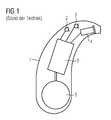
- the amplifier is usually integrated in a signal processing unit. This basic structure is in FIG. 1 using the example of a behind-the-ear hearing aid shown. In a hearing aid housing 1 for carrying behind the ear, one or more microphones 2 for receiving the sound from the environment are installed.
- a signal processing unit 3 which is also integrated in the hearing aid housing 1, processes the microphone signals and amplifies them.
- the output signal of the signal processing unit 3 is transmitted to a loudspeaker or earpiece 4, which outputs an acoustic signal.
- the sound is optionally transmitted via a sound tube, which is fixed with an earmold in the ear canal, to the eardrum of the device carrier.
- the power supply of the hearing device and in particular the signal processing unit 3 is effected by a likewise integrated into the hearing aid housing 1 battery. 5
- a carrying hook is usually attached to the hearing aid housing, which serves to hang the hearing aid on an auricle. Through the carrying hook sound, which is produced in the hearing aid housing, passed through to a sound tube, which leads the amplified sound to the ear canal.
- the sound tube In a hearing aid type, the sound tube is placed on the carrying hook at the free end of the carrying hook. The sound tube therefore has a correspondingly large diameter.
- a very thin sound tube is used, which can hardly be put on a carrying hook, and therefore are firmly installed in a small carrying hook. Such small carrying hooks and thin sound tubes are optically less conspicuous, which is why they are preferred by many users.
- the transmission of sound from the hearing aid housing or loudspeaker to the auditory canal depends essentially on the sound tube and wearing hook used. Therefore, when adjusting the hearing aid to adjust the sound gain depending on the used sound tube or carrying hook. Consequently, before using the hearing aid, the hearing aid wearer must definitely indicate to the acoustician which type of wearing hook or sound tube he will use. A later change of the carrying hook or sound tube makes a completely new adaptation necessary.
- a microphone arrangement for hearing aids which can be switched into a directional and in an omnidirectional mode.
- the microphone assembly has a front and rear sound inlet for this purpose.
- the microphone assembly has a switch which is movable for directional operation between a first position in which the rear sound inlet is closed for omnidirectional operation and a second position in which the rear sound inlet is unlocked.
- a circuit detects the position of the switch and selects a microphone output based on the detected position.
- the object of the present invention is to simplify the fitting of a hearing aid, in particular with regard to the choice of the type of a carrying hook.
- a hearing device with a housing which contains a signal processing device and which has a sound outlet, wherein a carrying hook for attaching the hearing device to an ear or head can be fastened to the sound outlet of the housing such that sound emerging from the sound outlet the carrying hook is guided, and wherein a sensor for detecting the type of the carrying hook is arranged in or on the housing, and the sensor controls the signal processing device in dependence on the detected type of the carrying hook.
- the hearing device automatically detects the type of carrying hook or a carrying hook sound tube combination and configures the signal processing accordingly.
- the hearing with a certain Carrying hook is fitted, once adjusted individually, because it automatically adjusts to the new wearing hook type or sound tube after replacing the carrying hook acoustically.
- the senor may be a distance sensor to detect a distance between a support hook and the housing. If the type of the carrying hook is thus coded by the distance between the housing and the carrying hook, the type of carrying hook can be determined via the distance sensor.
- the senor may be a pressure sensor to detect a pressure exerted by a support hook on a surface of the pressure sensor. This makes it possible to differentiate types of wearing hooks, for example, in that they have pressure surfaces whose distance from the housing varies in a manner similar to that of the aforementioned distance sensor. At a smaller distance is then generated for example by a spring more pressure than at a greater distance.
- the senor may be a magnetic sensor which responds to a magnetic or magnetizable element in a carrying hook.
- a magnetic sensor usually proves to be very robust and durable.
- a gain of the signal processing device is controllable with the sensor.
- the output signal of the hearing device can be acoustically adjusted exactly to the carrying hook or the sound tube attached thereto.
- the hearing device can be designed as a BTE hearing aid.
- a hearing aid wearer even after adjusting easily the ability to change its carrying hook, and the hearing aid automatically detects the new type of carrying hook and adjusts the signal processing accordingly.
- a hearing system with a hearing device as described above as well as a first carrying hook of a first type and a second carrying hook of a second type can be provided on the whole.
- the first carrying hook cooperates with the sensor, while the second carrying hook does not.
- the sensor merely has to decide binary, whether a first or second type of carrying hook is attached to the hearing device.
- the first carrying hook is a carrying hook onto which a sound tube can be plugged
- the second carrying hook is a carrying hook into which a sound tube is firmly inserted, wherein the sound tube of the second carrying hook is significantly smaller in diameter than that of the first wearing hook. This allows the hearing aid to automatically separate carrier hooks with sonic tubes of different diameters.
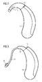
- FIG. 2 BTE hearing aid shown has a housing 10 to which a carrying hook 11 is attached.
- the sound which is generated by the signal processing device within the hearing aid housing 10, forwarded to the outside.
- a sound tube would beberichtstecken on the conical end of the carrying hook. This sound tube must have a correspondingly large inner diameter, so that the pointed end of the carrying hook can be inserted into the sound tube.
- the support hook 11 is typically attached to a fitting (in FIG. 2 not visible), which conducts the sound from the hearing aid housing 10 and thus serves as a sound outlet of the housing.
- a sensor 13 On the front side of the housing 10, to which the carrying hook 11 is fastened, there is a sensor 13. In the present case, this is a pressure sensor with a push button. An outer surface of the carrying hook 11, which is directed in the mounted on the housing 10 state of the carrying hook 11 to the front side of the housing 10, presses against this push button or piston of the pressure sensor 13. The pressure sensor registers the pressing of the piston.
- This sensor information is interpreted for the signal processing of the hearing device to the effect that a conventional support hook 11 is applied with attachable sound tube to the hearing aid housing 10.
- the signal processing device thereby switches into a first processing profile, with which the A-kustik of the concrete carrying hook and sound tube is taken into account.
- the gain is optionally adapted to the specific channel of the hearing aid (wearing hook with sound tube).
- FIG. 3 In FIG. 3 is to the hearing aid housing 10 against the carrying hook 11 very small carrying hook 14 infected with a thin sound tube 15. At the free end of the sound tube 15 is an adapter 16 for connecting an ear piece, which is intended to fix the sound tube in the ear canal.
- the ear piece itself is in FIG. 3 not shown.
- the sound tube 15 has a relatively small outside diameter (smaller than the tip of the carrying hook 11 from FIG. 2 ) and is here firmly inserted into the small carrying hook 14, glued or poured. Because of its small inner diameter, it can not be plugged onto the large carrying hook 11.
- This small carrying hook / tube combination 14, 15 is preferred by many hearing aid users because of the optically low conspicuousness.
- FIG. 3 It can be seen that the small carrying hook 14 does not touch the pressure sensor and in particular its push button or piston. There is thus no pressure exerted on the pressure sensor 13, so that a corresponding sensor signal is used by the signal processing device that a matched for the support hook-hose combination 14, 15 gain (second processing profile) is performed in the hearing aid. Based on the sensor signal, the hearing aid signal processing can thus automatically distinguish which sound output signal is to be generated in order to achieve optimum acoustic matching.
- the various wearing hooks must be coded accordingly.
- the distance of the pressure surface of the support hook to the end face of the hearing aid housing can be used for the coding.
- a third type of wearing hook could be characterized in that the pressure surface of the carrying hook directly touches the front side of the hearing aid housing 10 when the carrying hook is attached to the hearing aid housing. The piston or push button of the pressure sensor 13 would then be completely depressed. The pressure sensor would then have to be able to distinguish the fully depressed state from the half depressed state and the uninjected state.
- the sensor for detecting the carrying hook or the carrying hook-hose combination can also be based on other physical principles than on the pressure. For example, a magnetic, an electrical, an optical or other type of sensor can be used. The coding of the Tragehakentyps can then be done in a corresponding manner. Also, these sensors may be designed to distinguish more than two types of tethers.
- the hearing aid manufacturer thus obtains the advantage that he can pre-set a hearing aid without knowing which wearing hook type the hearing aid wearer will use.
- the hearing aid wearer can subsequently also select, for example, between a conventional carrying hook and a carrying hook with reduced size and the hearing aid then automatically changes the signal processing depending on the attached carrying hook. Not only can the gain be changed automatically, but also, for example, feedback reduction algorithms and other functions.
Landscapes
- Otolaryngology (AREA)
- Engineering & Computer Science (AREA)
- Health & Medical Sciences (AREA)
- General Health & Medical Sciences (AREA)
- Physics & Mathematics (AREA)
- Neurosurgery (AREA)
- Acoustics & Sound (AREA)
- Signal Processing (AREA)
- Manufacturing & Machinery (AREA)
- Headphones And Earphones (AREA)
- Details Of Connecting Devices For Male And Female Coupling (AREA)
- Helmets And Other Head Coverings (AREA)
- Measurement Of The Respiration, Hearing Ability, Form, And Blood Characteristics Of Living Organisms (AREA)
- Supports Or Holders For Household Use (AREA)
Abstract
Description
- Die vorliegende Erfindung betrifft eine Hörvorrichtung mit einem Gehäuse, das eine Signalverarbeitungseinrichtung beinhaltet und das einen Schallauslass besitzt, wobei an dem Schallauslass des Gehäuses ein Tragehaken zum Anbringen der Hörvorrichtung an einem Ohr oder Kopf derart befestigbar ist, dass aus dem Schallauslass austretender Schall durch den Tragehaken geleitet wird. Unter einer Hörvorrichtung wird hier jedes in oder am Ohr bzw. am Kopf tragbare schallausgebende Gerät verstanden, insbesondere ein Hörgerät, ein Headset, Kopfhörer und dergleichen.
- Hörgeräte sind tragbare Hörvorrichtungen, die zur Versorgung von Schwerhörenden dienen. Um den zahlreichen individuellen Bedürfnissen entgegenzukommen, werden unterschiedliche Bauformen von Hörgeräten wie Hinter-dem-Ohr-Hörgeräte (HdO), Hörgerät mit externem Hörer (RIC: receiver in the canal) und In-dem-Ohr-Hörgeräte (IdO), z.B. auch Concha-Hörgeräte oder Kanal-Hörgeräte (ITE, CIC), bereitgestellt. Die beispielhaft aufgeführten Hörgeräte werden am Außenohr oder im Gehörgang getragen. Darüber hinaus stehen auf dem Markt aber auch Knochenleitungshörhilfen, implantierbare oder vibrotaktile Hörhilfen zur Verfügung. Dabei erfolgt die Stimulation des geschädigten Gehörs entweder mechanisch oder elektrisch.
- Hörgeräte besitzen prinzipiell als wesentliche Komponenten einen Eingangswandler, einen Verstärker und einen Ausgangswandler. Der Eingangswandler ist in der Regel ein Schallempfänger, z. B. ein Mikrofon, und/oder ein elektromagnetischer Empfänger, z. B. eine Induktionsspule. Der Ausgangswandler ist meist als elektroakustischer Wandler, z. B. Miniaturlautsprecher, oder als elektromechanischer Wandler, z. B. Knochenleitungshörer, realisiert. Der Verstärker ist üblicherweise in eine Signalverarbeitungseinheit integriert. Dieser prinzipielle Aufbau ist in
FIG 1 am Beispiel eines Hinter-dem-Ohr-Hörgeräts dargestellt. In ein Hörgerätegehäuse 1 zum Tragen hinter dem Ohr sind ein oder mehrere Mikrofone 2 zur Aufnahme des Schalls aus der Umgebung eingebaut. Eine Signalverarbeitungseinheit 3, die ebenfalls in das Hörgerätegehäuse 1 integriert ist, verarbeitet die Mikrofonsignale und verstärkt sie. Das Ausgangssignal der Signalverarbeitungseinheit 3 wird an einen Lautsprecher bzw. Hörer 4 übertragen, der ein akustisches Signal ausgibt. Der Schall wird gegebenenfalls über einen Schallschlauch, der mit einer Otoplastik im Gehörgang fixiert ist, zum Trommelfell des Geräteträgers übertragen. Die Energieversorgung des Hörgeräts und insbesondere die der Signalverarbeitungseinheit 3 erfolgt durch eine ebenfalls ins Hörgerätegehäuse 1 integrierte Batterie 5. - Bei HdO-Hörgeräten wird üblicherweise ein Tragehaken an das Hörgerätegehäuse angebracht, der dazu dient, das Hörgerät an eine Ohrmuschel zu hängen. Über den Tragehaken wird Schall, der in dem Hörgerätegehäuse produziert wird, hindurch zu einem Schallschlauch geleitet, welcher den verstärkten Schall zum Gehörgang führt.
- Bei einem Hörgerätetyp wird der Schallschlauch am freien Ende des Tragehakens auf den Tragehaken gesteckt. Der Schallschlauch weist daher einen entsprechend großen Durchmesser auf. Bei einem anderen Hörgerätetyp, wird ein sehr dünner Schallschlauch eingesetzt, der sich kaum mehr auf einen Tragehaken aufstecken lassen, und der deshalb in einen kleinen Tragehaken fest eingebaut sind. Derartig kleine Tragehaken und dünne Schallschläuche sind optisch weniger auffällig, weswegen sie von zahlreichen Nutzern bevorzugt werden.
- Die Übertragung des Schalls vom Hörgerätegehäuse bzw. Lautsprecher zum Gehörgang hängt wesentlich von dem eingesetzten Schallschlauch und Tragehaken ab. Daher ist bei der Anpassung des Hörgeräts die Schallverstärkung in Abhängigkeit von dem eingesetzten Schallschlauch bzw. Tragehaken einzustellen. Folglich muss der Hörgeräteträger dem Akustiker vor der Benutzung des Hörgeräts definitiv angeben, welchen Typ von Tragehaken bzw. Schallschlauch er verwenden wird. Ein späterer Wechsel des Tragehakens bzw. Schallschlauchs macht eine vollständig neue Anpassung notwendig.
- Aus der Patentschrift
US 7,245,728 B2 ist eine Mikrofonanordnung für Hörgeräte bekannt, welche sich in einen direktionalen und in einen omnidirektionalen Modus schalten lässt. Die Mikrofonanordnung besitzt hierzu einen Vorderseiten- und Rückseiten-Schalleinlass. Darüber hinaus besitzt die Mikrofonanordnung einen Schalter, der zwischen einer ersten Position, in welcher der rückseitige Schalleinlass verschlossen ist, für den Omnidirektionalbetrieb und einer zweiten Position, in welcher der rückseitige Schalleinlass unverschlossen ist, für den Direktionalbetrieb bewegbar ist. Eine Schaltung detektiert die Position des Schalters und wählt ein Mikrofonausgangssignal auf der Basis der detektierten Position. - Die Aufgabe der vorliegenden Erfindung besteht darin, das Anpassen eines Hörgeräts zu vereinfachen insbesondere im Hinblick auf die Wahl des Typs eines Tragehakens.
- Erfindungsgemäß wird diese Aufgabe gelöst durch eine Hörvorrichtung mit einem Gehäuse, das eine Signalverarbeitungseinrichtung beinhaltet und das einen Schallauslass besitzt, wobei an dem Schallauslass des Gehäuses ein Tragehaken zum Anbringen der Hörvorrichtung an einem Ohr oder Kopf derart befestigbar ist, dass aus dem Schallauslass austretender Schall durch den Tragehaken geleitet wird, und wobei ein Sensor zum Erfassen des Typs des Tragehakens in oder an dem Gehäuse angeordnet ist, und der Sensor die Signalverarbeitungseinrichtung in Abhängigkeit von dem erfassten Typ des Tragehakens steuert.
- In vorteilhafter Weise ist es somit möglich, dass die Hörvorrichtung automatisch den Typ des Tragehakens bzw. einer Tragehaken-Schallschlauch-Kombination erkennt und die Signalverarbeitung entsprechend konfiguriert. Damit genügt es im günstigsten Fall, dass die Hörvorrichtung, die mit einem bestimmten Tragehaken ausgestattet ist, einmal individuell angepasst wird, denn sie stellt sich nach Austausch des Tragehakens automatisch auf den neuen Tragehakentyp bzw. Schallschlauch akustisch um.
- In einer speziellen Ausführungsform kann der Sensor ein Abstandssensor sein, um einen Abstand zwischen einem Tragehaken und dem Gehäuse zu erfassen. Wenn der Typ des Tragehakens somit über den Abstand zwischen Gehäuse und Tragehaken kodiert ist, lässt sich so der Typ des Tragehakens über den Abstandssensor feststellen.
- Alternativ kann der Sensor ein Drucksensor sein, um einen Druck zu erfassen, den ein Tragehaken auf eine Fläche des Drucksensors ausübt. Damit können Typen von Tragehaken beispielsweise dadurch unterschieden werden, dass sie Druckflächen besitzen, deren Abstand zu dem Gehäuse ähnlich wie bei dem genannten Abstandssensor variiert. Bei geringerem Abstand wird dann beispielsweise durch eine Feder mehr Druck erzeugt als bei einem größeren Abstand.
- Weiterhin kann der Sensor ein Magnetsensor sein, der auf ein magnetisches oder magnetisierbares Element in einem Tragehaken reagiert. Ein derartiger Magnetsensor erweist sich in der Regel als sehr robust und langlebig.
- Gemäß einer weiteren Ausführungsform ist eine Verstärkung der Signalverarbeitungseinrichtung mit dem Sensor steuerbar. Damit kann das Ausgangssignal der Hörvorrichtung akustisch exakt an den Tragehaken bzw. den daran befestigten Schallschlauch angepasst werden.
- Wie bereits angedeutet wurde, kann die Hörvorrichtung als HdO-Hörgerät ausgebildet sein. Damit hat ein Hörgeräteträger auch nach dem Anpassen ohne weiteres die Möglichkeit, seinen Tragehaken zu wechseln, und das Hörgerät erkennt automatisch den neuen Typ von Tragehaken und stellt die Signalverarbeitung entsprechend ein.
- Somit kann insgesamt ein Hörsystem mit einer oben beschriebenen Hörvorrichtung sowie einem ersten Tragehaken eines ersten Typs und einem zweiten Tragehaken eines zweiten Typs bereitgestellt werden. Gemäß einer speziellen Ausführungsform wirkt der erste Tragehaken mit dem Sensor zusammen, während der zweite Tragehaken dies nicht tut. Demnach muss der Sensor lediglich binär entscheiden, ob ein erster oder zweiter Typ von Tragehaken an der Hörvorrichtung angebracht ist.
- Vorzugsweise handelt es sich bei dem ersten Tragehaken um einen Tragehaken, auf den ein Schallschlauch aufsteckbar ist, während der zweite Tragehaken ein Tragehaken ist, in den ein Schallschlauch fest eingesetzt ist, wobei der Schallschlauch des zweiten Tragehakens im Durchmesser deutlich kleiner ist als der des ersten Tragehakens. Damit kann das Hörsystem Tragehaken mit Schallschläuchen unterschiedlichen Durchmessers automatisch voneinander unterscheiden.
- Die vorliegende Erfindung ist anhand der beigefügten Zeichnungen näher erläutert, in denen zeigen:
- FIG 1
- den prinzipiellen Aufbau eines Hörgeräts gemäß dem Stand der Technik;
- FIG 2
- ein HdO-Hörgerät mit einem Tragehaken eines ersten Typs und
- FIG 3
- ein HdO-Hörgerät mit einem Tragehaken eines zweiten Typs.
- Die nachfolgend näher geschilderten Ausführungsbeispiele stellen bevorzugte Ausführungsformen der vorliegenden Erfindung dar.
- Das in
FIG 2 dargestellte HdO-Hörgerät besitzt ein Gehäuse 10, an dem ein Tragehaken 11 befestigt ist. In dem Tragehaken 11 ist der Schallkanal 12 angedeutet, der den Schall, welcher von der Signalverarbeitungseinrichtung innerhalb des Hörgerätegehäuses 10 erzeugt wird, nach außen weiterleitet. Am freien Ende des Tragehakens 11 wäre ein Schallschlauch auf das konisch gebildete Ende des Tragehakens aufzustecken. Dieser Schallschlauch muss einen entsprechend großen Innendurchmesser aufweisen, so dass das spitze Ende des Tragehakens in den Schallschlauch einsteckbar ist. - Der Tragehaken 11 ist typischerweise an einem Anschlussstück befestigt (in
FIG 2 nicht sichtbar), das den Schall aus dem Hörgerätegehäuse 10 leitet und so als Schallauslass des Gehäuses dient. An der Stirnseite des Gehäuses 10, an der auch der Tragehaken 11 befestigt ist, befindet sich ein Sensor 13. Im vorliegenden Fall handelt es sich um einen Drucksensor mit einem Druckknopf. Eine Außenfläche des Tragehakens 11, die im auf das Gehäuse 10 aufgesetzten Zustand des Tragehakens 11 zu der Stirnseite des Gehäuses 10 gerichtet ist, drückt gegen diesen Druckknopf bzw. Kolben des Drucksensors 13. Der Drucksensor registriert das Eindrücken des Kolbens. Diese Sensorinformation wird für die Signalverarbeitung des Hörgeräts dahingehend interpretiert, dass ein üblicher Tragehaken 11 mit aufsteckbarem Schallschlauch auf das Hörgerätegehäuse 10 aufgebracht ist. Die Signalverarbeitungseinrichtung schaltet hierdurch in ein erstes Verarbeitungsprofil, mit dem die A-kustik des konkreten Tragehakens und Schallschlauchs berücksichtigt wird. Insbesondere wird die Verstärkung ggf. kanalspezifisch an den Hörgeräteausgang (Tragehaken mit Schallschlauch) angepasst. - In
FIG 3 ist an das Hörgerätegehäuse 10 ein gegenüber dem Tragehaken 11 sehr kleiner Tragehaken 14 mit einem dünnen Schallschlauch 15 angesteckt. Am freien Ende des Schallschlauchs 15 befindet sich ein Adapter 16 zum Anstecken eines Ohrstücks, welches den Schallschlauch im Gehörgang fixieren soll. Das Ohrstück selbst ist inFIG 3 nicht dargestellt. - Der Schallschlauch 15 besitzt einen verhältnismäßig kleinen Außendurchmesser (kleiner als die Spitze des Tragehakens 11 von
FIG 2 ) und ist hier fest in den kleinen Tragehaken 14 eingesteckt, eingeklebt oder eingegossen. Wegen seines kleinen Innendurchmessers kann er nicht auf den großen Tragehaken 11 aufgesteckt werden. Diese kleine Tragehaken-Schlauch-Kombination 14, 15 wird von vielen Hörgerätenutzern wegen der optisch geringen Auffälligkeit bevorzugt. - Aus
FIG 3 ist zu erkennen, dass der kleine Tragehaken 14 den Drucksensor und insbesondere seinen Druckknopf bzw. Kolben nicht berührt. Es wird somit auf den Drucksensor 13 kein Druck ausgeübt, sodass ein korrespondierendes Sensorsignal von der Signalverarbeitungseinrichtung dafür genutzt wird, dass eine für die Tragehaken-Schlauch-Kombination 14, 15 angepasste Verstärkung (zweites Verarbeitungsprofil) im Hörgerät durchgeführt wird. Anhand des Sensorsignals kann somit die Hörgerätesignalverarbeitung automatisch unterscheiden, welches Schallausgangssignal zu erzeugen ist, um eine optimale akustische Anpassung zu erzielen. - In dem Beispiel der
FIG 2 und 3 findet lediglich eine nähere Unterscheidung zwischen zwei Tragehakentypen statt. Dabei wird die Tatsache ausgenutzt, dass der Tragehaken einmal mit dem Sensor in Wechselwirkung tritt und im anderen Fall nicht. - Sollen mehr als zwei unterschiedliche Tragehakentypen (im vorliegenden Dokument synonym mit Typen von Tragehaken-Schallschlauch-Kombinationen) durch die Hörgerätesignalverarbeitung automatisch erkannt werden, so müssen die verschiedenen Tragehaken entsprechend kodiert werden. In dem Beispiel eines Drucksensors kann für das Kodieren beispielsweise der Abstand der Druckfläche des Tragehakens zu der Stirnfläche des Hörgerätegehäuses verwendet werden. In dem konkreten Beispiel analog zu den
FIG 2 und 3 könnte ein dritter Tragehakentyp dadurch gekennzeichnet werden, dass die Druckfläche des Tragehakens direkt mit der Stirnseite des Hörgerätegehäuses 10 in Berührung gerät, wenn der Tragehaken auf das Hörgerätegehäuse aufgesteckt ist. Der Kolben bzw. Druckknopf des Drucksensors 13 wäre dann vollständig eingedrückt. Der Drucksensor müsste dann den vollständig eingedrückten Zustand von dem halbeingedrückten Zustand und dem nicht eingedrückten Zustand unterscheiden können. - Der Sensor zum Erkennen des Tragehakens bzw. der Tragehaken-Schlauch-Kombination kann auch auf anderen physikalischen Prinzipien als auf dem Druck beruhen. Beispielsweise kann auch ein magnetischer, ein elektrischer, ein optischer oder andersartiger Sensor eingesetzt werden. Die Kodierung des Tragehakentyps kann dann auf entsprechende Weise erfolgen. Auch können diese Sensoren dazu ausgelegt sein, mehr als zwei Tragehakentypen zu unterscheiden.
- Der Hörgerätehersteller erhält somit den Vorteil, dass er ein Hörgerät vorab einstellen kann, ohne zu wissen, welchen Tragehakentyp der Hörgeräteträger verwenden wird. Darüber hinaus ergeben sich auch Vorteile für Serienfertigungskonzepte, da der Hörgeräteträger auch nachträglich beispielsweise zwischen einem üblichen Tragehaken und einem Tragehaken mit reduzierter Größe wählen kann und das Hörgerät dann je nach angebrachtem Tragehaken die Signalverarbeitung automatisch ändert. Dabei kann nicht nur die Verstärkung automatisch geändert werden, sondern beispielsweise auch Rückkopplungsreduktionsalgorithmen und andere Funktionen.
Claims (10)
- Hörvorrichtung mit- einem Gehäuse (10), das eine Signalverarbeitungseinrichtung beinhaltet und das einen Schallauslass besitzt, wobei- an dem Schallauslass des Gehäuses (10) ein Tragehaken (11, 14) zum Anbringen der Hörvorrichtung an einem Ohr oder Kopf derart befestigbar ist, dass aus dem Schallauslass austretender Schall durch den Tragehaken (11, 14) geleitet wird,dadurch gekennzeichnet, dass- ein Sensor (13) zum Erfassen des Typs des Tragehakens (11, 14) in oder an dem Gehäuse (10) angeordnet ist, und- der Sensor (13) die Signalverarbeitungseinrichtung in Abhängigkeit von dem erfassten Typ des Tragehakens (11, 14) steuert.
- Hörvorrichtung nach Anspruch 1, wobei der Sensor (13) ein Abstandssensor ist, um einen Abstand zwischen einem Tragehaken (11, 14) und dem Gehäuse (10) zu erfassen.
- Hörvorrichtung nach Anspruch 1, wobei der Sensor (13) ein Drucksensor ist, um einen Druck zu erfassen, den ein Tragehaken (11, 14) auf eine Fläche des Drucksensors ausübt.
- Hörvorrichtung nach Anspruch 1, wobei der Sensor (13) ein Magnetsensor ist, der auf ein magnetisches oder magnetisierbares Element in einem Tragehaken (11, 14) reagiert.
- Hörvorrichtung nach einem der vorhergehenden Ansprüche, wobei mit dem Sensor (13) eine Verstärkung der Signalverarbeitungseinrichtung steuerbar ist.
- Hörvorrichtung nach einem der vorhergehenden Ansprüche, die als hinter-dem-Ohr-Hörgerät ausgebildet ist.
- Hörsystem mit einer Hörvorrichtung nach einem der Ansprüche 1 bis 5 und einem ersten Tragehaken (11) eines ersten Typs und einem zweiten Tragehaken (14) eines zweiten Typs.
- Hörsystem nach Anspruch 7, wobei der erste Tragehaken (11) mit dem Sensor (13) zusammenwirkt und der zweite Tragehaken (14) mit dem Sensor nicht zusammenwirkt.
- Hörsystem nach Anspruch 7 oder 8, wobei auf den ersten Tragehaken (11) ein Schallschlauch aufsteckbar ist.
- Hörvorrichtung nach einem der Ansprüche 7 bis 9, wobei in den zweiten Tragehaken (14) ein Schallschlauch (15) fest eingesetzt ist.
Applications Claiming Priority (1)
| Application Number | Priority Date | Filing Date | Title |
|---|---|---|---|
| DE102009008045A DE102009008045B3 (de) | 2009-02-09 | 2009-02-09 | Hörvorrichtung mit Tragehakenerkennung |
Publications (3)
| Publication Number | Publication Date |
|---|---|
| EP2217009A2 true EP2217009A2 (de) | 2010-08-11 |
| EP2217009A3 EP2217009A3 (de) | 2010-10-27 |
| EP2217009B1 EP2217009B1 (de) | 2011-06-15 |
Family
ID=42238767
Family Applications (1)
| Application Number | Title | Priority Date | Filing Date |
|---|---|---|---|
| EP09180880A Revoked EP2217009B1 (de) | 2009-02-09 | 2009-12-29 | Hörvorrichtung mit Tragehakenerkennung |
Country Status (5)
| Country | Link |
|---|---|
| US (1) | US8477971B2 (de) |
| EP (1) | EP2217009B1 (de) |
| AT (1) | ATE513428T1 (de) |
| DE (1) | DE102009008045B3 (de) |
| DK (1) | DK2217009T3 (de) |
Cited By (1)
| Publication number | Priority date | Publication date | Assignee | Title |
|---|---|---|---|---|
| CN108810693A (zh) * | 2018-05-28 | 2018-11-13 | Oppo广东移动通信有限公司 | 设备控制方法及相关产品 |
Families Citing this family (1)
| Publication number | Priority date | Publication date | Assignee | Title |
|---|---|---|---|---|
| EP3226582A1 (de) * | 2016-03-29 | 2017-10-04 | Oticon Medical A/S | Hörgerät mit modularem verbindungsmittel |
Citations (1)
| Publication number | Priority date | Publication date | Assignee | Title |
|---|---|---|---|---|
| US7245728B2 (en) | 1999-07-12 | 2007-07-17 | Etymotic Research, Inc. | Microphone for hearing aid and communications applications having switchable polar and frequency response characteristics |
Family Cites Families (6)
| Publication number | Priority date | Publication date | Assignee | Title |
|---|---|---|---|---|
| DK0548379T3 (da) | 1991-12-17 | 1994-11-28 | Siemens Audiologische Technik | Høreapparat |
| US5824022A (en) | 1996-03-07 | 1998-10-20 | Advanced Bionics Corporation | Cochlear stimulation system employing behind-the-ear speech processor with remote control |
| US6594707B1 (en) * | 1999-09-15 | 2003-07-15 | 3Com Corporation | Smart communication agent |
| US6748094B1 (en) * | 2000-03-03 | 2004-06-08 | Advanced Bionics Corporation | Connector system for BTE hearing devices |
| DE10333293A1 (de) * | 2003-07-22 | 2005-03-03 | Siemens Audiologische Technik Gmbh | Anschlussstück für Hörgerätetragehaken |
| CN101263738B (zh) * | 2005-10-17 | 2012-07-18 | 唯听助听器公司 | 助听器的可互换式声学系统以及助听器 |
-
2009
- 2009-02-09 DE DE102009008045A patent/DE102009008045B3/de not_active Expired - Fee Related
- 2009-12-29 EP EP09180880A patent/EP2217009B1/de not_active Revoked
- 2009-12-29 AT AT09180880T patent/ATE513428T1/de active
- 2009-12-29 DK DK09180880.8T patent/DK2217009T3/da active
-
2010
- 2010-02-09 US US12/702,468 patent/US8477971B2/en not_active Expired - Fee Related
Patent Citations (1)
| Publication number | Priority date | Publication date | Assignee | Title |
|---|---|---|---|---|
| US7245728B2 (en) | 1999-07-12 | 2007-07-17 | Etymotic Research, Inc. | Microphone for hearing aid and communications applications having switchable polar and frequency response characteristics |
Cited By (1)
| Publication number | Priority date | Publication date | Assignee | Title |
|---|---|---|---|---|
| CN108810693A (zh) * | 2018-05-28 | 2018-11-13 | Oppo广东移动通信有限公司 | 设备控制方法及相关产品 |
Also Published As
| Publication number | Publication date |
|---|---|
| DE102009008045B3 (de) | 2010-09-02 |
| US20100202646A1 (en) | 2010-08-12 |
| US8477971B2 (en) | 2013-07-02 |
| EP2217009B1 (de) | 2011-06-15 |
| DK2217009T3 (da) | 2011-09-26 |
| ATE513428T1 (de) | 2011-07-15 |
| EP2217009A3 (de) | 2010-10-27 |
Similar Documents
| Publication | Publication Date | Title |
|---|---|---|
| EP1993324B1 (de) | Ohrpassstück mit Adapterdichtung | |
| EP1909536B1 (de) | Hinter-dem-Ohr-Hörgerät mit externem, optischem Mikrofon | |
| DE102008017194B4 (de) | Hörvorrichtung zum Tragen in der Ohrmuschel mit individuellem Formteil und Verfahren zum Herstellen einer Hörvorrichtung | |
| EP2026605A1 (de) | Hörereinrichtung mit elastisch gelagertem Hörer | |
| EP2389015A2 (de) | Hörvorrichtung mit passiver, tief im Gehörgang sitzender Einheit | |
| EP2180724A1 (de) | Ohrstück mit Stegen | |
| EP1962555A2 (de) | Hinter-dem-Ohr-Hörgerät mit magnetisch befestigtem Ohrhaken | |
| EP2373064B1 (de) | Verfahren und Anordnung zur Sprachsteuerung von binaurales Hörgeräten | |
| EP2007172B1 (de) | Schallausgangsröhrchen mit 2-Komponenten-Aufbau | |
| EP2023665A1 (de) | Hörereinrichtung mit beeinflussbarer Schallaustrittsrichtung | |
| EP2043387A1 (de) | Schallschlauch für eine Hörvorrichtung | |
| DE102010043496B3 (de) | Hörgerät und Verfahren zum Betrieb eines Hörgeräts mit einem Feuchtigkeitssensor | |
| EP2217009B1 (de) | Hörvorrichtung mit Tragehakenerkennung | |
| EP2393310B1 (de) | Tief-Ohrkanal-Hörinstrument | |
| EP2180725B1 (de) | Hörereinrichtung mit schwingungsentkoppeltem Hörer | |
| DE102008031581B4 (de) | Hörhilfesystem mit Mikrofonmodul | |
| EP1909533A2 (de) | Schallleiter und Hörvorrichtung | |
| EP2180723B1 (de) | Hörereinrichtung mit beweglichem Hörer | |
| US20090028363A1 (en) | Method for setting a hearing system with a perceptive model for binaural hearing and corresponding hearing system | |
| EP1998593A1 (de) | Ohrstück für eine Hörvorrichtung mit Sicherungsring | |
| EP2552129B1 (de) | Hörvorrichtung mit speziellem Schallkanal | |
| EP2619997B1 (de) | Kommunikationssystem mit Telefon und Hörvorrichtung sowie Übertragungsverfahren | |
| EP2604046A1 (de) | Verfahren zum betreiben eines hörgeräts und entsprechendes hörgerät | |
| DE102011075739A1 (de) | Kommunikationssystem mit Hörvorrichtung und Telefon sowie Betriebsverfahren | |
| EP2001264B1 (de) | Tragehaken mit Metallabschnitt für ein Hörgerät |
Legal Events
| Date | Code | Title | Description |
|---|---|---|---|
| PUAI | Public reference made under article 153(3) epc to a published international application that has entered the european phase |
Free format text: ORIGINAL CODE: 0009012 |
|
| AK | Designated contracting states |
Kind code of ref document: A2 Designated state(s): AT BE BG CH CY CZ DE DK EE ES FI FR GB GR HR HU IE IS IT LI LT LU LV MC MK MT NL NO PL PT RO SE SI SK SM TR |
|
| AX | Request for extension of the european patent |
Extension state: AL BA RS |
|
| PUAL | Search report despatched |
Free format text: ORIGINAL CODE: 0009013 |
|
| AK | Designated contracting states |
Kind code of ref document: A3 Designated state(s): AT BE BG CH CY CZ DE DK EE ES FI FR GB GR HR HU IE IS IT LI LT LU LV MC MK MT NL NO PL PT RO SE SI SK SM TR |
|
| AX | Request for extension of the european patent |
Extension state: AL BA RS |
|
| GRAP | Despatch of communication of intention to grant a patent |
Free format text: ORIGINAL CODE: EPIDOSNIGR1 |
|
| 17P | Request for examination filed |
Effective date: 20101122 |
|
| RIC1 | Information provided on ipc code assigned before grant |
Ipc: H04R 25/00 20060101AFI20101208BHEP |
|
| GRAS | Grant fee paid |
Free format text: ORIGINAL CODE: EPIDOSNIGR3 |
|
| GRAA | (expected) grant |
Free format text: ORIGINAL CODE: 0009210 |
|
| AK | Designated contracting states |
Kind code of ref document: B1 Designated state(s): AT BE BG CH CY CZ DE DK EE ES FI FR GB GR HR HU IE IS IT LI LT LU LV MC MK MT NL NO PL PT RO SE SI SK SM TR |
|
| REG | Reference to a national code |
Ref country code: CH Ref legal event code: EP Ref country code: CH Ref legal event code: NV Representative=s name: SIEMENS SCHWEIZ AG Ref country code: GB Ref legal event code: FG4D Free format text: NOT ENGLISH |
|
| REG | Reference to a national code |
Ref country code: IE Ref legal event code: FG4D Free format text: LANGUAGE OF EP DOCUMENT: GERMAN |
|
| REG | Reference to a national code |
Ref country code: DE Ref legal event code: R096 Ref document number: 502009000795 Country of ref document: DE Effective date: 20110721 |
|
| REG | Reference to a national code |
Ref country code: DK Ref legal event code: T3 |
|
| REG | Reference to a national code |
Ref country code: NL Ref legal event code: VDEP Effective date: 20110615 |
|
| PG25 | Lapsed in a contracting state [announced via postgrant information from national office to epo] |
Ref country code: HR Free format text: LAPSE BECAUSE OF FAILURE TO SUBMIT A TRANSLATION OF THE DESCRIPTION OR TO PAY THE FEE WITHIN THE PRESCRIBED TIME-LIMIT Effective date: 20110615 Ref country code: LT Free format text: LAPSE BECAUSE OF FAILURE TO SUBMIT A TRANSLATION OF THE DESCRIPTION OR TO PAY THE FEE WITHIN THE PRESCRIBED TIME-LIMIT Effective date: 20110615 Ref country code: SE Free format text: LAPSE BECAUSE OF FAILURE TO SUBMIT A TRANSLATION OF THE DESCRIPTION OR TO PAY THE FEE WITHIN THE PRESCRIBED TIME-LIMIT Effective date: 20110615 Ref country code: NO Free format text: LAPSE BECAUSE OF FAILURE TO SUBMIT A TRANSLATION OF THE DESCRIPTION OR TO PAY THE FEE WITHIN THE PRESCRIBED TIME-LIMIT Effective date: 20110915 |
|
| PG25 | Lapsed in a contracting state [announced via postgrant information from national office to epo] |
Ref country code: GR Free format text: LAPSE BECAUSE OF FAILURE TO SUBMIT A TRANSLATION OF THE DESCRIPTION OR TO PAY THE FEE WITHIN THE PRESCRIBED TIME-LIMIT Effective date: 20110916 Ref country code: LV Free format text: LAPSE BECAUSE OF FAILURE TO SUBMIT A TRANSLATION OF THE DESCRIPTION OR TO PAY THE FEE WITHIN THE PRESCRIBED TIME-LIMIT Effective date: 20110615 Ref country code: SI Free format text: LAPSE BECAUSE OF FAILURE TO SUBMIT A TRANSLATION OF THE DESCRIPTION OR TO PAY THE FEE WITHIN THE PRESCRIBED TIME-LIMIT Effective date: 20110615 Ref country code: FI Free format text: LAPSE BECAUSE OF FAILURE TO SUBMIT A TRANSLATION OF THE DESCRIPTION OR TO PAY THE FEE WITHIN THE PRESCRIBED TIME-LIMIT Effective date: 20110615 Ref country code: CY Free format text: LAPSE BECAUSE OF FAILURE TO SUBMIT A TRANSLATION OF THE DESCRIPTION OR TO PAY THE FEE WITHIN THE PRESCRIBED TIME-LIMIT Effective date: 20110615 |
|
| PG25 | Lapsed in a contracting state [announced via postgrant information from national office to epo] |
Ref country code: NL Free format text: LAPSE BECAUSE OF FAILURE TO SUBMIT A TRANSLATION OF THE DESCRIPTION OR TO PAY THE FEE WITHIN THE PRESCRIBED TIME-LIMIT Effective date: 20110615 |
|
| REG | Reference to a national code |
Ref country code: IE Ref legal event code: FD4D |
|
| PG25 | Lapsed in a contracting state [announced via postgrant information from national office to epo] |
Ref country code: IS Free format text: LAPSE BECAUSE OF FAILURE TO SUBMIT A TRANSLATION OF THE DESCRIPTION OR TO PAY THE FEE WITHIN THE PRESCRIBED TIME-LIMIT Effective date: 20111015 Ref country code: CZ Free format text: LAPSE BECAUSE OF FAILURE TO SUBMIT A TRANSLATION OF THE DESCRIPTION OR TO PAY THE FEE WITHIN THE PRESCRIBED TIME-LIMIT Effective date: 20110615 Ref country code: PT Free format text: LAPSE BECAUSE OF FAILURE TO SUBMIT A TRANSLATION OF THE DESCRIPTION OR TO PAY THE FEE WITHIN THE PRESCRIBED TIME-LIMIT Effective date: 20111017 Ref country code: IE Free format text: LAPSE BECAUSE OF FAILURE TO SUBMIT A TRANSLATION OF THE DESCRIPTION OR TO PAY THE FEE WITHIN THE PRESCRIBED TIME-LIMIT Effective date: 20110615 Ref country code: EE Free format text: LAPSE BECAUSE OF FAILURE TO SUBMIT A TRANSLATION OF THE DESCRIPTION OR TO PAY THE FEE WITHIN THE PRESCRIBED TIME-LIMIT Effective date: 20110615 |
|
| PG25 | Lapsed in a contracting state [announced via postgrant information from national office to epo] |
Ref country code: PL Free format text: LAPSE BECAUSE OF FAILURE TO SUBMIT A TRANSLATION OF THE DESCRIPTION OR TO PAY THE FEE WITHIN THE PRESCRIBED TIME-LIMIT Effective date: 20110615 Ref country code: SK Free format text: LAPSE BECAUSE OF FAILURE TO SUBMIT A TRANSLATION OF THE DESCRIPTION OR TO PAY THE FEE WITHIN THE PRESCRIBED TIME-LIMIT Effective date: 20110615 |
|
| PLBI | Opposition filed |
Free format text: ORIGINAL CODE: 0009260 |
|
| 26 | Opposition filed |
Opponent name: WIDEX A/S/GN RESOUND A/S OTICON A/S/PHONAK AG Effective date: 20120314 |
|
| PLAX | Notice of opposition and request to file observation + time limit sent |
Free format text: ORIGINAL CODE: EPIDOSNOBS2 |
|
| PG25 | Lapsed in a contracting state [announced via postgrant information from national office to epo] |
Ref country code: IT Free format text: LAPSE BECAUSE OF FAILURE TO SUBMIT A TRANSLATION OF THE DESCRIPTION OR TO PAY THE FEE WITHIN THE PRESCRIBED TIME-LIMIT Effective date: 20110615 |
|
| REG | Reference to a national code |
Ref country code: DE Ref legal event code: R026 Ref document number: 502009000795 Country of ref document: DE Effective date: 20120314 |
|
| BERE | Be: lapsed |
Owner name: SIEMENS MEDICAL INSTRUMENTS PTE. LTD. Effective date: 20111231 |
|
| PG25 | Lapsed in a contracting state [announced via postgrant information from national office to epo] |
Ref country code: MC Free format text: LAPSE BECAUSE OF NON-PAYMENT OF DUE FEES Effective date: 20111231 |
|
| PLBB | Reply of patent proprietor to notice(s) of opposition received |
Free format text: ORIGINAL CODE: EPIDOSNOBS3 |
|
| PG25 | Lapsed in a contracting state [announced via postgrant information from national office to epo] |
Ref country code: BE Free format text: LAPSE BECAUSE OF NON-PAYMENT OF DUE FEES Effective date: 20111231 |
|
| PG25 | Lapsed in a contracting state [announced via postgrant information from national office to epo] |
Ref country code: MK Free format text: LAPSE BECAUSE OF FAILURE TO SUBMIT A TRANSLATION OF THE DESCRIPTION OR TO PAY THE FEE WITHIN THE PRESCRIBED TIME-LIMIT Effective date: 20110615 Ref country code: MT Free format text: LAPSE BECAUSE OF FAILURE TO SUBMIT A TRANSLATION OF THE DESCRIPTION OR TO PAY THE FEE WITHIN THE PRESCRIBED TIME-LIMIT Effective date: 20110615 |
|
| PG25 | Lapsed in a contracting state [announced via postgrant information from national office to epo] |
Ref country code: ES Free format text: LAPSE BECAUSE OF FAILURE TO SUBMIT A TRANSLATION OF THE DESCRIPTION OR TO PAY THE FEE WITHIN THE PRESCRIBED TIME-LIMIT Effective date: 20110926 Ref country code: SM Free format text: LAPSE BECAUSE OF FAILURE TO SUBMIT A TRANSLATION OF THE DESCRIPTION OR TO PAY THE FEE WITHIN THE PRESCRIBED TIME-LIMIT Effective date: 20110615 |
|
| PG25 | Lapsed in a contracting state [announced via postgrant information from national office to epo] |
Ref country code: LU Free format text: LAPSE BECAUSE OF NON-PAYMENT OF DUE FEES Effective date: 20111229 |
|
| PG25 | Lapsed in a contracting state [announced via postgrant information from national office to epo] |
Ref country code: BG Free format text: LAPSE BECAUSE OF FAILURE TO SUBMIT A TRANSLATION OF THE DESCRIPTION OR TO PAY THE FEE WITHIN THE PRESCRIBED TIME-LIMIT Effective date: 20110915 |
|
| PG25 | Lapsed in a contracting state [announced via postgrant information from national office to epo] |
Ref country code: TR Free format text: LAPSE BECAUSE OF FAILURE TO SUBMIT A TRANSLATION OF THE DESCRIPTION OR TO PAY THE FEE WITHIN THE PRESCRIBED TIME-LIMIT Effective date: 20110615 |
|
| PG25 | Lapsed in a contracting state [announced via postgrant information from national office to epo] |
Ref country code: HU Free format text: LAPSE BECAUSE OF FAILURE TO SUBMIT A TRANSLATION OF THE DESCRIPTION OR TO PAY THE FEE WITHIN THE PRESCRIBED TIME-LIMIT Effective date: 20110615 |
|
| APBM | Appeal reference recorded |
Free format text: ORIGINAL CODE: EPIDOSNREFNO |
|
| APBP | Date of receipt of notice of appeal recorded |
Free format text: ORIGINAL CODE: EPIDOSNNOA2O |
|
| APAH | Appeal reference modified |
Free format text: ORIGINAL CODE: EPIDOSCREFNO |
|
| APBM | Appeal reference recorded |
Free format text: ORIGINAL CODE: EPIDOSNREFNO |
|
| APBP | Date of receipt of notice of appeal recorded |
Free format text: ORIGINAL CODE: EPIDOSNNOA2O |
|
| APBQ | Date of receipt of statement of grounds of appeal recorded |
Free format text: ORIGINAL CODE: EPIDOSNNOA3O |
|
| REG | Reference to a national code |
Ref country code: DE Ref legal event code: R082 Ref document number: 502009000795 Country of ref document: DE Representative=s name: FDST PATENTANWAELTE FREIER DOERR STAMMLER TSCH, DE |
|
| REG | Reference to a national code |
Ref country code: DE Ref legal event code: R082 Ref document number: 502009000795 Country of ref document: DE Representative=s name: FDST PATENTANWAELTE FREIER DOERR STAMMLER TSCH, DE |
|
| REG | Reference to a national code |
Ref country code: DE Ref legal event code: R082 Ref document number: 502009000795 Country of ref document: DE Representative=s name: FDST PATENTANWAELTE FREIER DOERR STAMMLER TSCH, DE Ref country code: DE Ref legal event code: R081 Ref document number: 502009000795 Country of ref document: DE Owner name: SIVANTOS PTE. LTD., SG Free format text: FORMER OWNER: SIEMENS MEDICAL INSTRUMENTS PTE. LTD., SINGAPORE, SG |
|
| RAP2 | Party data changed (patent owner data changed or rights of a patent transferred) |
Owner name: SIVANTOS PTE. LTD. |
|
| REG | Reference to a national code |
Ref country code: FR Ref legal event code: PLFP Year of fee payment: 7 |
|
| REG | Reference to a national code |
Ref country code: AT Ref legal event code: MM01 Ref document number: 513428 Country of ref document: AT Kind code of ref document: T Effective date: 20141229 |
|
| PG25 | Lapsed in a contracting state [announced via postgrant information from national office to epo] |
Ref country code: AT Free format text: LAPSE BECAUSE OF NON-PAYMENT OF DUE FEES Effective date: 20141229 |
|
| REG | Reference to a national code |
Ref country code: FR Ref legal event code: PLFP Year of fee payment: 8 |
|
| REG | Reference to a national code |
Ref country code: FR Ref legal event code: PLFP Year of fee payment: 9 |
|
| PGFP | Annual fee paid to national office [announced via postgrant information from national office to epo] |
Ref country code: FR Payment date: 20171219 Year of fee payment: 9 Ref country code: DK Payment date: 20171221 Year of fee payment: 9 |
|
| RAP2 | Party data changed (patent owner data changed or rights of a patent transferred) |
Owner name: SIVANTOS PTE. LTD. |
|
| PGFP | Annual fee paid to national office [announced via postgrant information from national office to epo] |
Ref country code: GB Payment date: 20171221 Year of fee payment: 9 Ref country code: CH Payment date: 20171221 Year of fee payment: 9 |
|
| REG | Reference to a national code |
Ref country code: DE Ref legal event code: R064 Ref document number: 502009000795 Country of ref document: DE Ref country code: DE Ref legal event code: R103 Ref document number: 502009000795 Country of ref document: DE |
|
| APBU | Appeal procedure closed |
Free format text: ORIGINAL CODE: EPIDOSNNOA9O |
|
| APBQ | Date of receipt of statement of grounds of appeal recorded |
Free format text: ORIGINAL CODE: EPIDOSNNOA3O |
|
| RDAF | Communication despatched that patent is revoked |
Free format text: ORIGINAL CODE: EPIDOSNREV1 |
|
| STAA | Information on the status of an ep patent application or granted ep patent |
Free format text: STATUS: PATENT REVOKED |
|
| RDAG | Patent revoked |
Free format text: ORIGINAL CODE: 0009271 |
|
| PGFP | Annual fee paid to national office [announced via postgrant information from national office to epo] |
Ref country code: DE Payment date: 20171219 Year of fee payment: 9 |
|
| REG | Reference to a national code |
Ref country code: CH Ref legal event code: PLX |
|
| 27W | Patent revoked |
Effective date: 20180316 |
|
| GBPR | Gb: patent revoked under art. 102 of the ep convention designating the uk as contracting state |
Effective date: 20180316 |
|
| PG25 | Lapsed in a contracting state [announced via postgrant information from national office to epo] |
Ref country code: LI Free format text: LAPSE BECAUSE OF THE APPLICANT RENOUNCES Effective date: 20110615 Ref country code: CH Free format text: LAPSE BECAUSE OF THE APPLICANT RENOUNCES Effective date: 20110615 |
|
| REG | Reference to a national code |
Ref country code: AT Ref legal event code: MA03 Ref document number: 513428 Country of ref document: AT Kind code of ref document: T Effective date: 20180316 |