EP2216644A2 - Procédé et dispositif destinés au contrôle de la qualité - Google Patents
Procédé et dispositif destinés au contrôle de la qualité Download PDFInfo
- Publication number
- EP2216644A2 EP2216644A2 EP09170161A EP09170161A EP2216644A2 EP 2216644 A2 EP2216644 A2 EP 2216644A2 EP 09170161 A EP09170161 A EP 09170161A EP 09170161 A EP09170161 A EP 09170161A EP 2216644 A2 EP2216644 A2 EP 2216644A2
- Authority
- EP
- European Patent Office
- Prior art keywords
- sensor
- receiver
- measuring
- workpiece
- crack
- Prior art date
- Legal status (The legal status is an assumption and is not a legal conclusion. Google has not performed a legal analysis and makes no representation as to the accuracy of the status listed.)
- Withdrawn
Links
Images

Classifications
-
- G—PHYSICS
- G01—MEASURING; TESTING
- G01B—MEASURING LENGTH, THICKNESS OR SIMILAR LINEAR DIMENSIONS; MEASURING ANGLES; MEASURING AREAS; MEASURING IRREGULARITIES OF SURFACES OR CONTOURS
- G01B11/00—Measuring arrangements characterised by the use of optical techniques
- G01B11/24—Measuring arrangements characterised by the use of optical techniques for measuring contours or curvatures
-
- G—PHYSICS
- G01—MEASURING; TESTING
- G01N—INVESTIGATING OR ANALYSING MATERIALS BY DETERMINING THEIR CHEMICAL OR PHYSICAL PROPERTIES
- G01N21/00—Investigating or analysing materials by the use of optical means, i.e. using sub-millimetre waves, infrared, visible or ultraviolet light
- G01N21/84—Systems specially adapted for particular applications
- G01N21/88—Investigating the presence of flaws or contamination
- G01N21/95—Investigating the presence of flaws or contamination characterised by the material or shape of the object to be examined
- G01N21/9515—Objects of complex shape, e.g. examined with use of a surface follower device
-
- G—PHYSICS
- G06—COMPUTING; CALCULATING OR COUNTING
- G06Q—INFORMATION AND COMMUNICATION TECHNOLOGY [ICT] SPECIALLY ADAPTED FOR ADMINISTRATIVE, COMMERCIAL, FINANCIAL, MANAGERIAL OR SUPERVISORY PURPOSES; SYSTEMS OR METHODS SPECIALLY ADAPTED FOR ADMINISTRATIVE, COMMERCIAL, FINANCIAL, MANAGERIAL OR SUPERVISORY PURPOSES, NOT OTHERWISE PROVIDED FOR
- G06Q10/00—Administration; Management
-
- G—PHYSICS
- G01—MEASURING; TESTING
- G01N—INVESTIGATING OR ANALYSING MATERIALS BY DETERMINING THEIR CHEMICAL OR PHYSICAL PROPERTIES
- G01N21/00—Investigating or analysing materials by the use of optical means, i.e. using sub-millimetre waves, infrared, visible or ultraviolet light
- G01N21/84—Systems specially adapted for particular applications
- G01N21/88—Investigating the presence of flaws or contamination
- G01N21/95—Investigating the presence of flaws or contamination characterised by the material or shape of the object to be examined
- G01N21/952—Inspecting the exterior surface of cylindrical bodies or wires
Definitions
- the present invention relates to a method and a device for quality inspection of a surface of a workpiece, in particular for detecting cracks in a workpiece.
- a method and apparatus for detecting cracks or holes in a bent pipe are not needed DE 196 00 176 A1 known.
- a sensor of this known device comprises a laser which emits a light beam. The light beam is reflected on the surface of the tube to be examined, and reflected light is received by the sensor again. When the jet encounters cracks or holes in the tube, it is scattered strongly, so that the intensity of the light beam received by the sensor is substantially reduced.
- a triangulation probe or sensor conventionally comprises a beam source, such as a laser, and a row of receiver elements onto which a spot illuminated by the laser is imaged through a lens becomes. From the location of the line to which the dot is mapped, information about the distance to the point can be derived. The intensity of the light reflected back to the triangulation sensor has no influence on the measured distance.
- a problem with the conventional device is that the intensity of the reflected beam is not only responsive to cracks or holes in the surface of the workpiece, but to any change in surface quality, such as rough or dull surface areas, stains, etc., which are of use value of the pipe are much less relevant than a crack. The probability of detection errors is therefore high.
- the object of the invention is to provide a method and an apparatus which enable a quality inspection of a surface of a workpiece in a short time, with a high degree of certainty and a low processing overhead.
- the output signal may be representative of the beam intensity received by the receiver. Since the preferred direction of the cracks is in the measurement plane, the probability is high that the receiver can "look" into a crack. The presence of a tear expresses Therefore, not as in the prior art by reducing the received beam intensity (for which there may be various other causes), but because the measuring beam illuminates the insides of the crack, the receiver gets to see a large illuminated area and provides a correspondingly intense Signal.
- the output signal of the receiver is representative of the distance between the sensor and the surface.
- the presence of a crack is indicated by a brief increase in the detected distance.
- the detection reliability can be increased by high-pass filtering the output signal of the receiver.
- the preferred direction is expediently chosen transversely to a tensile stress acting in the workpiece, since this is the direction in which cracks caused by the tensile stress will essentially arise.
- the method is particularly useful applicable to a pressed onto a shaft workpiece.
- the direction of the tension is the circumferential direction of the workpiece.
- the preferred direction of cracks in the workpiece is always axial and radial.
- Surfaces of the workpiece may conveniently be scanned by rotating the workpiece and sensor relative to each other about an axis of the shaft.
- This axis is expediently in the measurement plane of the sensor.
- the first sensor is a triangulation sensor whose receiver comprises a row of receiver elements extending in the measuring plane.
- the triangulation sensor can be used to simultaneously check the dimensional accuracy of the workpiece with the crack detection.
- the drive means preferably comprise a rotary drive with an axis of rotation extending in the direction of measurement in order to rotate the workpiece and the first sensor with respect to one another.
- a linear drive with a feed direction that is parallel to the axis of rotation can serve to place different surface sections, which are distributed along the axis of rotation, of the workpiece to be checked in succession in front of the sensor for examination.
- a second sensor is provided with a measurement plane that crosses the measurement plane of the first sensor.
- Such a sensor when it examines the same surface as the first sensor, is less sensitive to cracks extending in the preferential direction than the first sensor, so that the reliability of the crack detection can be increased by comparing the measurement signals of the two sensors.
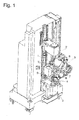
- Fig. 1 shows a perspective view of a device for the quality inspection of camshafts.
- a camshaft 1 to be tested is clamped vertically in the device between two jaws 2 and rotatable about its longitudinal axis by a motor in a jaw 2.
- the camshaft 1 is of any conventional type.
- the camshaft 1 shown by way of example has a solid shaft with a total of eight pressed-on cams 3 and one Sprocket 4, which serves as a reference for the angular orientation of the cam 3.
- a carriage 5 vertically slidable on a rack of the apparatus carries four triangulation sensors 6, 7, 8, 9.
- Each of these triangulation sensors comprises a laser as a source of a light beam and a line of photosensitive elements such as a CCD line facing one to be inspected Surface of the camshaft 1 receives reflected radiation of the laser.
- the beam direction of the laser and the orientation of the CCD line define a measuring plane in each triangulation sensor which, in the case of the sensors 6 and 8, crosses the axis of the camshaft at an angle of 45 °, the sensor 7 is perpendicular to the axis of the camshaft 1 and Sensor 9 is aligned parallel to the axis.
- the sensor 9 is horizontally and transversely displaceable to its measuring plane, so that it can extend both along the axis of the camshaft 1 and laterally offset against this.
- a staggered arrangement of the sensor 9 is useful if it is to be examined with this strongly inclined surfaces, such as the flanks of teeth of a gear on the camshaft 1. In the context of the crack test on the cam 3, however, only that positioning of the sensor 9 is of interest, in which the axis of the camshaft 1 extends in the measuring plane.
- the lasers of the sensors 7 and 9 emit in the horizontal direction and are located on the same Height so that they scan in the course of rotation of the camshaft 1 about its axis a same track on the circumference of one of the cams 3.
- the cams 3 are by pressing on the shaft under tension in the circumferential direction. If this stress leads to cracking in a cam 3, then a crack on a peripheral surface of the cam extends substantially in the axial direction.
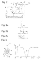
- Fig. 2 shows a schematic representation of the sensor 9, the peripheral surface of a cam 3 opposite.
- the cam 3 is shown partially in section along the measurement plane of the sensor 9; in the sectional plane, the cam 3 has a superficial crack 10.
- a laser 11 of the triangulation sensor 9 radiates perpendicularly to the cam 3.
- a lens 13 images a surface region of the cam 3 illuminated by the beam 12 of the laser 11 onto a CCD line 14 with elements 14-1, 14-2,..., 14-n.
- An arranged in the beam path of the reflected light narrow-band color filter 15 is tuned to the wavelength of the laser 11 in order to make the CCD line 14 insensitive to other colored scattered light from the environment.
- the laser 11 would illuminate only a point 16 on the surface of the cam 3, that of the lens 13 on a small number of elements at location 16 'of the CCD line 14 would be pictured.
- a typical detection result in such a case would be the in Fig. 2a intensity distribution shown: the bars drawn over the CCD line 14 each represent the light intensity received from a single element of the line. A single element 14-i of the CCD line 14 receives a majority of the reflected light, the intensity at adjacent elements is significantly lower.
- the image 16 'of the point 16 is exactly centered on the illuminated strongest member 14 i.
- the distance detectable by means of the triangulation sensor 9 increases; since the crack 10 extends in the direction of the CCD line 14, a region 18 illuminated by the beam 12 is imaged onto the CCD line 14 at an edge of the crack 10 at 18 '.
- the intensity distribution on the CCD line 14 can then be described by way of example in FIG Fig. 2c a portion of the beam 12 which strikes adjacent to the crack 10 provides, albeit at a reduced level, the same intensity distribution as in FIG Fig. 2a , with a maximum at element 14 i .
- a second maximum of the intensity at an element 14 k corresponds to the image of the region 18.
- a conversion of the intensity distributions obtained in the CCD line 14 into distance values can take place in an evaluation electronics of the sensor 9 itself, or a digital data processor can be connected directly to the CCD line in order to read out the intensity values of each individual element and to carry out their evaluation. In both cases, a conversion of the obtained intensities into a distance measured value can take place by calculating a center of gravity of the intensity distribution.
- FIGS. 2a, 2b shown distributions is the focus on the element 14 i or between the elements 14 j and 14 j + 1 and gives the distance between the sensor and cam 3 exactly.
- 2c is the focus between the elements 14 i and 14 k , and as a distance measurement, a value is obtained which lies between the distance from the sensor to the cam surface and the distance from the sensor to the bottom of the crack 10.
- this is not critical since it only depends on the detection of the presence of the crack 10, but not on the knowledge of its depth.
- Fig. 3 shows by way of example the course of the measured distance d as a function of the angle of rotation ⁇ between sensor 9 and cam 3 in the case of the cam 3 shown in the left part of the figure by way of example in a plan view with crack 10.
- the measurement signal is substantially constant; when the tip 19 passes the sensor 9, the distance measurement has a wide minimum 20.
- a crack 10 on the base circle of the cam provides an isolated peak 21 in the distance trace.
- the signal processor performs various quality assessments. On the one hand, it compares the global profile of the distance measurement curve with a specification in order to determine whether the orientation and radius of the tip 19 and, if applicable, the course of flanks 22 of the cam 3 on both sides of the tip 19 correspond to a specification. If this is not the case, the relevant camshaft must be discarded and reworked if necessary.
- a second assessment concerns the search for cracks.
- it is expedient to provide high-pass filtering of the distance measurement values of the signal Fig. 3 which substantially suppresses the minimum 20 due to the tip 19 and allows the peak 21 to pass. If the amount of the high-pass filtered distance measurement signal exceeds a suitably set limit, it can be concluded that there is a crack.
- a particularly easy to implement in a digital signal processor high-pass filtering is a numerical differentiation according to the rotation angle ⁇ .
- An alternative strategy for crack detection additionally uses the triangulation sensor 7 whose measuring plane is perpendicular to that of the sensor 9.
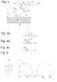
- Fig. 4 shows one too Fig. 2 Analogous representation of the triangulation sensor 7.
- the measuring plane of the sensor 7, which is also the cutting plane of the figure, crosses the crack 10 in the surface of the cam to be examined 3.
- the measurement results of the sensors 9 and 7 do not differ.
- the beam from the laser 11 of the sensor 7 hits the crack 10
- no reflected light reaches the CCD line 14.
- a portion of the beam 12 incident on the surface of the cam 3 adjacent the crack 10 provides an intensity distribution as in FIG Fig. 4a shown with an intensity maximum at element 14 i .
- the distribution differs from the distribution obtained at the intact surface Fig. 2a only by their intensity, but not by their position or form.
- the focus of the intensity distribution according to Fig. 4a is thus the same as according to Fig. 2a ie, the sensor 7 does not "see" the crack 10.
- the measurement signal delivered by the sensor 7 in the course of one revolution of the camshaft 1, shown in the graph of FIG Fig. 5 differs from the one of the Fig. 3 only by the absence of the peak 21. If the two sensors 7, 9 are used with mutually orthogonal measurement planes to scan a same track on the circumference of a cam 3, then the presence of a crack can also be detected by the signal processor, the difference between the Distance measurement values of the two sensors 7, 9 forms. This difference is significantly different from zero only at one crack. Therefore, it is decided that there is a crack when the difference in any selected range of the scanned track exceeds a suitably selected limit.
- Yet another strategy for detecting a piss is to form, for each scanned point on the surface of the cam 3, the difference in the intensity distributions obtained at the individual elements of the CCD array 14 of the sensors 7, 9.
- the signal processor is the difference between the intensity distribution of the Fig. 4a and the distribution obtained at the same point on the cam surface Fig. 2c (for the sake of clarity as Fig. 4b shown again), the distribution of the Fig. 4c receive. This is based exclusively on that reflected light which the sensor 9 receives from the crack 10. From the fact that even a difference distribution with significantly positive intensities is obtained, the signal processor can already infer the presence of a crack. The position of the illuminated area 18 'on the CCD line 14 of the sensor 9 allows even a conclusion on the dimensions of the crack.
- the two triangulation sensors 7, 9 can be replaced for the purposes of the method according to the invention by a single combined sensor, in which, as in Fig. 6 light reflected from a single laser 11 and reflected at the surface to be inspected is captured by two CCD lines 14 which extend in directions perpendicular to each other and to the beam direction of the laser 11. Of the two CCD lines 14 only the parallel to the crack 10 of the cam 3 is capable of to see the crack. For the measurement of the shape of the cam 3, the intensity distribution of any of the two CCD lines 14 or the sum of both from an adder circuit 23 can be used; For crack detection, a differential circuit 24 may be provided accordingly.
- triangulation sensors considered so far each provide a laser beam perpendicular to the axis of rotation of the camshaft 1 and are therefore essentially suitable for detecting cracks in circumferentially oriented surfaces.
- cracks can also be detected on other surfaces, such as the faces of cams, gears or the like.
- Fig. 7 shows a schematic section through a portion of a camshaft with two triangulation sensors 25 for detecting radial cracks on opposite end faces 26 of the cam 3.
- the laser beams 12 of the sensors 25 at an acute angle to the axis of the camshaft 1 to.
- the axis of the camshaft 1 extends in the sectional plane of the figure, which is the same measurement plane of the two triangulation sensors 25.
Landscapes
- General Physics & Mathematics (AREA)
- Physics & Mathematics (AREA)
- Business, Economics & Management (AREA)
- Engineering & Computer Science (AREA)
- Operations Research (AREA)
- Life Sciences & Earth Sciences (AREA)
- Human Resources & Organizations (AREA)
- Quality & Reliability (AREA)
- Strategic Management (AREA)
- Tourism & Hospitality (AREA)
- Entrepreneurship & Innovation (AREA)
- General Business, Economics & Management (AREA)
- Economics (AREA)
- Theoretical Computer Science (AREA)
- Health & Medical Sciences (AREA)
- Marketing (AREA)
- Chemical & Material Sciences (AREA)
- Analytical Chemistry (AREA)
- Biochemistry (AREA)
- General Health & Medical Sciences (AREA)
- Immunology (AREA)
- Pathology (AREA)
- Length Measuring Devices By Optical Means (AREA)
- Investigating Materials By The Use Of Optical Means Adapted For Particular Applications (AREA)
- Investigating Or Analyzing Materials By The Use Of Ultrasonic Waves (AREA)
Applications Claiming Priority (1)
| Application Number | Priority Date | Filing Date | Title |
|---|---|---|---|
| DE102009007570.4A DE102009007570B4 (de) | 2009-02-04 | 2009-02-04 | Verfahren und Vorrichtung zur Qualitätsprüfung |
Publications (2)
| Publication Number | Publication Date |
|---|---|
| EP2216644A2 true EP2216644A2 (fr) | 2010-08-11 |
| EP2216644A3 EP2216644A3 (fr) | 2016-06-01 |
Family
ID=41396095
Family Applications (1)
| Application Number | Title | Priority Date | Filing Date |
|---|---|---|---|
| EP09170161.5A Withdrawn EP2216644A3 (fr) | 2009-02-04 | 2009-09-14 | Procédé et dispositif destinés au contrôle de la qualité |
Country Status (2)
| Country | Link |
|---|---|
| EP (1) | EP2216644A3 (fr) |
| DE (1) | DE102009007570B4 (fr) |
Cited By (3)
| Publication number | Priority date | Publication date | Assignee | Title |
|---|---|---|---|---|
| EP2623952A1 (fr) * | 2012-02-03 | 2013-08-07 | Hartmut Pabst | Procédé et dispositif de détection de fissures en surface |
| CN103852472A (zh) * | 2013-08-12 | 2014-06-11 | 中国科学院合肥物质科学研究院 | 一种发动机凸轮轴圆周面检测装置 |
| CN110907467A (zh) * | 2019-12-02 | 2020-03-24 | 葛攀 | 一种电梯配件生产用裂纹检测设备 |
Citations (1)
| Publication number | Priority date | Publication date | Assignee | Title |
|---|---|---|---|---|
| DE3033260A1 (de) * | 1979-09-07 | 1981-03-26 | Diffracto Ltd., Windsor, Ontario | Vorrichtung und verfahren zum kontrollieren von werkstuecken |
Family Cites Families (8)
| Publication number | Priority date | Publication date | Assignee | Title |
|---|---|---|---|---|
| DE3307591C2 (de) * | 1983-03-03 | 1986-06-05 | Kraftwerk Union AG, 4330 Mülheim | Verfahren zur optischen Kontrolle der Oberfläche eines Prüfgutes |
| JPH01277743A (ja) * | 1988-04-28 | 1989-11-08 | Yasunaga:Kk | カムシヤフトの表面検査装置 |
| JPH06190479A (ja) * | 1992-12-22 | 1994-07-12 | Mazda Motor Corp | 組立式カムシャフトの製造方法 |
| DE19600176B4 (de) | 1996-01-04 | 2007-08-16 | Schwarze-Robitec Gmbh & Co. Kg | Verfahren zum Betrieb einer Rohrbiegemaschine |
| US20050174567A1 (en) * | 2004-02-09 | 2005-08-11 | Mectron Engineering Company | Crack detection system |
| DE102006013584B4 (de) * | 2006-03-22 | 2014-07-10 | Benteler Automobiltechnik Gmbh | Vorrichtung zum Vermessen von Bauteilen |
| DE202006017076U1 (de) * | 2006-11-08 | 2007-01-04 | Fraunhofer-Gesellschaft zur Förderung der angewandten Forschung e.V. | Vorrichtung zur Inspektion einer Rohrleitung |
| DE102007026900A1 (de) * | 2007-06-11 | 2008-12-18 | Siemens Ag | Auswerten der Oberflächenstruktur von Bauelementen unter Verwendung von unterschiedlichen Präsentationswinkeln |
-
2009
- 2009-02-04 DE DE102009007570.4A patent/DE102009007570B4/de active Active
- 2009-09-14 EP EP09170161.5A patent/EP2216644A3/fr not_active Withdrawn
Patent Citations (1)
| Publication number | Priority date | Publication date | Assignee | Title |
|---|---|---|---|---|
| DE3033260A1 (de) * | 1979-09-07 | 1981-03-26 | Diffracto Ltd., Windsor, Ontario | Vorrichtung und verfahren zum kontrollieren von werkstuecken |
Non-Patent Citations (1)
| Title |
|---|
| PROF J ZHANG: "Vorlesung: Angewandte Sensorik", 16 July 2019 (2019-07-16), XP055605913, Retrieved from the Internet <URL:https://tams.informatik.uni-hamburg.de/lehre/2003ws/vorlesung/angewandte_sensorik/vorlesung_06.pdf> [retrieved on 20190716] * |
Cited By (4)
| Publication number | Priority date | Publication date | Assignee | Title |
|---|---|---|---|---|
| EP2623952A1 (fr) * | 2012-02-03 | 2013-08-07 | Hartmut Pabst | Procédé et dispositif de détection de fissures en surface |
| CN103852472A (zh) * | 2013-08-12 | 2014-06-11 | 中国科学院合肥物质科学研究院 | 一种发动机凸轮轴圆周面检测装置 |
| CN103852472B (zh) * | 2013-08-12 | 2016-08-10 | 中国科学院合肥物质科学研究院 | 一种发动机凸轮轴圆周面检测装置 |
| CN110907467A (zh) * | 2019-12-02 | 2020-03-24 | 葛攀 | 一种电梯配件生产用裂纹检测设备 |
Also Published As
| Publication number | Publication date |
|---|---|
| DE102009007570B4 (de) | 2017-08-17 |
| DE102009007570A1 (de) | 2010-08-05 |
| EP2216644A3 (fr) | 2016-06-01 |
Similar Documents
| Publication | Publication Date | Title |
|---|---|---|
| DE10062254C2 (de) | Verfahren und Vorrichtung zum Charakterisieren einer Oberfläche und Verfahren und Vorrichtung zur Ermittlung einer Formanomalie einer Oberfläche | |
| EP1057727B1 (fr) | Procede et appareil pour controler des bouts de cigarettes | |
| DE2602001C3 (de) | Vorrichtung zur Überprüfung einer bearbeiteten Oberfläche eines Werkstucks | |
| EP3321628A1 (fr) | Dispositif de mesure de coordonnées doté d'un capteur optique et procédé correspondant | |
| CH666547A5 (de) | Optisch-elektronisches messverfahren, eine dafuer erforderliche einrichtung und deren verwendung. | |
| DE102010007396B4 (de) | Verfahren und Vorrichtung zum optischen Inspizieren eines Prüflings mit einer zumindest teilweise reflektierenden Oberfläche | |
| WO2012159870A1 (fr) | Procédé et dispositif permettant de déterminer l'épaisseur d'un produit laminé | |
| WO2020221818A1 (fr) | Procédé et dispositif de contrôle de roues dentées | |
| DE102012112121B4 (de) | Verfahren und Vorrichtung zur zerstörungsfreien Prüfung eines rotationssymmetrischen Werkstücks, welches Abschnitte verschiedener Durchmesser aufweist | |
| EP2762832A1 (fr) | Mesure optique des points individuels | |
| DD283682A5 (de) | Verfahren und vorrichtung zur optischen erfassung des rauheitsprofils einer materialoberflaeche | |
| DE102009007570B4 (de) | Verfahren und Vorrichtung zur Qualitätsprüfung | |
| EP0984244B1 (fr) | Procédé et dispositif de mesure | |
| DE19914962C2 (de) | Optoelektronische Vorrichtung | |
| DE10006663B4 (de) | Verfahren zur Vermessung von langwelligen Oberflächenstrukturen | |
| EP3023737B1 (fr) | Procédé de mesure de surface sans contact avec correction de mesure | |
| EP2957858A1 (fr) | Procédé et dispositif de mesure destinés à vérifier un alésage cylindrique | |
| EP2623952B1 (fr) | Procédé et dispositif de détection de fissures en surface | |
| EP2572186A1 (fr) | Procédé et dispositif pour caractériser des structures de surface pyramidales sur un substrat | |
| DE102004011404A1 (de) | Messgerät zur Bestimmung der Geradheit von Wellen oder Wellentunneln | |
| DE10151332B4 (de) | Vorrichtung zur optischen Messung von Oberflächeneigenschaften | |
| EP1682884A1 (fr) | Procede de determination quantitative de la longueur d'une region de zone molle d'une piece partiellement durcie | |
| EP2578991B1 (fr) | Capteur optique | |
| DE3703504C2 (fr) | ||
| DE4037934C2 (de) | Verfahren und Vorrichtung zur Messung von Verformungen an Prüfkörpern in Prüfmaschinen |
Legal Events
| Date | Code | Title | Description |
|---|---|---|---|
| PUAI | Public reference made under article 153(3) epc to a published international application that has entered the european phase |
Free format text: ORIGINAL CODE: 0009012 |
|
| AK | Designated contracting states |
Kind code of ref document: A2 Designated state(s): AT BE BG CH CY CZ DE DK EE ES FI FR GB GR HR HU IE IS IT LI LT LU LV MC MK MT NL NO PL PT RO SE SI SK SM TR |
|
| AX | Request for extension of the european patent |
Extension state: AL BA RS |
|
| RAP1 | Party data changed (applicant data changed or rights of an application transferred) |
Owner name: MBB FERTIGUNGSTECHNIK GMBH |
|
| PUAL | Search report despatched |
Free format text: ORIGINAL CODE: 0009013 |
|
| AK | Designated contracting states |
Kind code of ref document: A3 Designated state(s): AT BE BG CH CY CZ DE DK EE ES FI FR GB GR HR HU IE IS IT LI LT LU LV MC MK MT NL NO PL PT RO SE SI SK SM TR |
|
| AX | Request for extension of the european patent |
Extension state: AL BA RS |
|
| RIC1 | Information provided on ipc code assigned before grant |
Ipc: G01N 21/952 20060101ALI20160428BHEP Ipc: G01N 21/95 20060101AFI20160428BHEP |
|
| 17P | Request for examination filed |
Effective date: 20161019 |
|
| RBV | Designated contracting states (corrected) |
Designated state(s): AT BE BG CH CY CZ DE DK EE ES FI FR GB GR HR HU IE IS IT LI LT LU LV MC MK MT NL NO PL PT RO SE SI SK SM TR |
|
| RAP1 | Party data changed (applicant data changed or rights of an application transferred) |
Owner name: AUMANN BEELEN GMBH |
|
| STAA | Information on the status of an ep patent application or granted ep patent |
Free format text: STATUS: EXAMINATION IS IN PROGRESS |
|
| 17Q | First examination report despatched |
Effective date: 20190723 |
|
| STAA | Information on the status of an ep patent application or granted ep patent |
Free format text: STATUS: EXAMINATION IS IN PROGRESS |
|
| STAA | Information on the status of an ep patent application or granted ep patent |
Free format text: STATUS: THE APPLICATION HAS BEEN WITHDRAWN |
|
| 18W | Application withdrawn |
Effective date: 20211206 |