EP2216508A2 - Turbinenleitstufe, Übergangskanal und Turbinentriebwerk aus Keramik-Matrix-Verbund - Google Patents
Turbinenleitstufe, Übergangskanal und Turbinentriebwerk aus Keramik-Matrix-Verbund Download PDFInfo
- Publication number
- EP2216508A2 EP2216508A2 EP20100152251 EP10152251A EP2216508A2 EP 2216508 A2 EP2216508 A2 EP 2216508A2 EP 20100152251 EP20100152251 EP 20100152251 EP 10152251 A EP10152251 A EP 10152251A EP 2216508 A2 EP2216508 A2 EP 2216508A2
- Authority
- EP
- European Patent Office
- Prior art keywords
- turbine
- ceramic matrix
- pressure turbine
- airfoil
- matrix composite
- Prior art date
- Legal status (The legal status is an assumption and is not a legal conclusion. Google has not performed a legal analysis and makes no representation as to the accuracy of the status listed.)
- Withdrawn
Links
Images


Classifications
-
- F—MECHANICAL ENGINEERING; LIGHTING; HEATING; WEAPONS; BLASTING
- F01—MACHINES OR ENGINES IN GENERAL; ENGINE PLANTS IN GENERAL; STEAM ENGINES
- F01D—NON-POSITIVE DISPLACEMENT MACHINES OR ENGINES, e.g. STEAM TURBINES
- F01D5/00—Blades; Blade-carrying members; Heating, heat-insulating, cooling or antivibration means on the blades or the members
- F01D5/12—Blades
- F01D5/14—Form or construction
- F01D5/18—Hollow blades, i.e. blades with cooling or heating channels or cavities; Heating, heat-insulating or cooling means on blades
- F01D5/187—Convection cooling
-
- F—MECHANICAL ENGINEERING; LIGHTING; HEATING; WEAPONS; BLASTING
- F01—MACHINES OR ENGINES IN GENERAL; ENGINE PLANTS IN GENERAL; STEAM ENGINES
- F01D—NON-POSITIVE DISPLACEMENT MACHINES OR ENGINES, e.g. STEAM TURBINES
- F01D17/00—Regulating or controlling by varying flow
- F01D17/10—Final actuators
- F01D17/12—Final actuators arranged in stator parts
- F01D17/14—Final actuators arranged in stator parts varying effective cross-sectional area of nozzles or guide conduits
- F01D17/16—Final actuators arranged in stator parts varying effective cross-sectional area of nozzles or guide conduits by means of nozzle vanes
- F01D17/162—Final actuators arranged in stator parts varying effective cross-sectional area of nozzles or guide conduits by means of nozzle vanes for axial flow, i.e. the vanes turning around axes which are essentially perpendicular to the rotor centre line
-
- F—MECHANICAL ENGINEERING; LIGHTING; HEATING; WEAPONS; BLASTING
- F01—MACHINES OR ENGINES IN GENERAL; ENGINE PLANTS IN GENERAL; STEAM ENGINES
- F01D—NON-POSITIVE DISPLACEMENT MACHINES OR ENGINES, e.g. STEAM TURBINES
- F01D5/00—Blades; Blade-carrying members; Heating, heat-insulating, cooling or antivibration means on the blades or the members
- F01D5/12—Blades
- F01D5/28—Selecting particular materials; Particular measures relating thereto; Measures against erosion or corrosion
- F01D5/282—Selecting composite materials, e.g. blades with reinforcing filaments
-
- F—MECHANICAL ENGINEERING; LIGHTING; HEATING; WEAPONS; BLASTING
- F01—MACHINES OR ENGINES IN GENERAL; ENGINE PLANTS IN GENERAL; STEAM ENGINES
- F01D—NON-POSITIVE DISPLACEMENT MACHINES OR ENGINES, e.g. STEAM TURBINES
- F01D5/00—Blades; Blade-carrying members; Heating, heat-insulating, cooling or antivibration means on the blades or the members
- F01D5/12—Blades
- F01D5/28—Selecting particular materials; Particular measures relating thereto; Measures against erosion or corrosion
- F01D5/284—Selection of ceramic materials
-
- F—MECHANICAL ENGINEERING; LIGHTING; HEATING; WEAPONS; BLASTING
- F01—MACHINES OR ENGINES IN GENERAL; ENGINE PLANTS IN GENERAL; STEAM ENGINES
- F01D—NON-POSITIVE DISPLACEMENT MACHINES OR ENGINES, e.g. STEAM TURBINES
- F01D9/00—Stators
- F01D9/02—Nozzles; Nozzle boxes; Stator blades; Guide conduits, e.g. individual nozzles
- F01D9/04—Nozzles; Nozzle boxes; Stator blades; Guide conduits, e.g. individual nozzles forming ring or sector
- F01D9/041—Nozzles; Nozzle boxes; Stator blades; Guide conduits, e.g. individual nozzles forming ring or sector using blades
-
- F—MECHANICAL ENGINEERING; LIGHTING; HEATING; WEAPONS; BLASTING
- F02—COMBUSTION ENGINES; HOT-GAS OR COMBUSTION-PRODUCT ENGINE PLANTS
- F02C—GAS-TURBINE PLANTS; AIR INTAKES FOR JET-PROPULSION PLANTS; CONTROLLING FUEL SUPPLY IN AIR-BREATHING JET-PROPULSION PLANTS
- F02C6/00—Plural gas-turbine plants; Combinations of gas-turbine plants with other apparatus; Adaptations of gas-turbine plants for special use
- F02C6/04—Gas-turbine plants providing heated or pressurised working fluid for other apparatus, e.g. without mechanical power output
- F02C6/06—Gas-turbine plants providing heated or pressurised working fluid for other apparatus, e.g. without mechanical power output providing compressed gas
- F02C6/08—Gas-turbine plants providing heated or pressurised working fluid for other apparatus, e.g. without mechanical power output providing compressed gas the gas being bled from the gas-turbine compressor
-
- F—MECHANICAL ENGINEERING; LIGHTING; HEATING; WEAPONS; BLASTING
- F04—POSITIVE - DISPLACEMENT MACHINES FOR LIQUIDS; PUMPS FOR LIQUIDS OR ELASTIC FLUIDS
- F04D—NON-POSITIVE-DISPLACEMENT PUMPS
- F04D27/00—Control, e.g. regulation, of pumps, pumping installations or pumping systems specially adapted for elastic fluids
- F04D27/02—Surge control
- F04D27/0207—Surge control by bleeding, bypassing or recycling fluids
-
- F—MECHANICAL ENGINEERING; LIGHTING; HEATING; WEAPONS; BLASTING
- F05—INDEXING SCHEMES RELATING TO ENGINES OR PUMPS IN VARIOUS SUBCLASSES OF CLASSES F01-F04
- F05D—INDEXING SCHEME FOR ASPECTS RELATING TO NON-POSITIVE-DISPLACEMENT MACHINES OR ENGINES, GAS-TURBINES OR JET-PROPULSION PLANTS
- F05D2300/00—Materials; Properties thereof
- F05D2300/60—Properties or characteristics given to material by treatment or manufacturing
- F05D2300/603—Composites; e.g. fibre-reinforced
- F05D2300/6033—Ceramic matrix composites [CMC]
-
- Y—GENERAL TAGGING OF NEW TECHNOLOGICAL DEVELOPMENTS; GENERAL TAGGING OF CROSS-SECTIONAL TECHNOLOGIES SPANNING OVER SEVERAL SECTIONS OF THE IPC; TECHNICAL SUBJECTS COVERED BY FORMER USPC CROSS-REFERENCE ART COLLECTIONS [XRACs] AND DIGESTS
- Y02—TECHNOLOGIES OR APPLICATIONS FOR MITIGATION OR ADAPTATION AGAINST CLIMATE CHANGE
- Y02T—CLIMATE CHANGE MITIGATION TECHNOLOGIES RELATED TO TRANSPORTATION
- Y02T50/00—Aeronautics or air transport
- Y02T50/60—Efficient propulsion technologies, e.g. for aircraft
Definitions
- the subject matter disclosed herein relates to gas turbines, and more specifically, to variable-area turbine nozzles and transition ducts within gas turbines.
- gas turbines combust a mixture of compressed air and fuel to produce hot combustion gases.
- the combustion gases may flow through one or more turbine components to generate power for a load and/or a compressor.
- Dual-shaft gas turbines may include a high-pressure turbine that drives a compressor and a low-pressure turbine that drives a load, such as a fan or a generator.
- the combustion gases may flow from the high-pressure turbine to the variable-area turbine nozzle of the low-pressure turbine through a transition duct. Due to the high temperature of the combustion gases, the transition duct and turbine nozzles may need to be designed to withstand high temperatures.
- the first-stage low-pressure turbine nozzle may need to be designed to provide a flow area that is variable as a function of aerodynamic load.
- a turbine engine in one embodiment, includes a high-pressure turbine, a low-pressure turbine, and a transition section configured to direct fluids from the high-pressure turbine to the low-pressure turbine. At least one component of the transition section is constructed of a ceramic matrix composite.
- a variable area turbine nozzle assembly includes at least one variable airfoil constructed of a ceramic matrix composite and at least one trunion configured to rotatably mount the at least one variable airfoil in a gas turbine engine.
- a transition duct includes a ceramic matrix composite housing that fluidly connects a high-pressure turbine to a low-pressure turbine.
- a gas turbine engine in yet another embodiment, includes a high-pressure turbine, a low-pressure turbine, a variable area turbine nozzle configured to direct combustion gases into the high-pressure turbine or the low-pressure turbine, and a transition duct configured to fluidly connect the high-pressure turbine and the low-pressure turbine.
- the transition duct, the variable area turbine nozzle, or a combination thereof is constructed of a ceramic matrix composite.
- gas turbines may include a high-pressure turbine and a low-pressure turbine fluidly connected by a transition duct that directs combustion gases from the high-pressure turbine to the low-pressure turbine.
- the combustion gases may pass through variable area turbine nozzles (VATNs) for optimizing the partial-load performance of the turbines.
- VATNs variable area turbine nozzles
- the VATNs may be adjusted to vary the flow velocity and angle of combustion gases within the gas turbine engine as a function of low-pressure turbine load.
- the transition duct and VATNs may be designed to withstand high temperatures.
- the transition duct and VATNs particularly those constructed of metallic superalloys, may be cooled using a portion of compressed air bled from the compressor.
- air bled from the compressor is necessarily not used for producing power, which correspondingly decreases the overall efficiency and output of the gas turbine engine.
- the transition duct and/or VATNs may have intricate geometries and sealing requirements, which in turn may increase the cost of the cooling designs.
- the need for variable area provides the opportunity for additional parasitic leakages of compressor airflow.
- the present disclosure describes gas turbines that include VATNs and transition ducts constructed of CMCs that may reduce or eliminate cooling requirements within the gas turbine engine. Reduced cooling requirements may allow more of the compressed air to be used for producing power, thus increasing the operating efficiency and output of the gas turbine. Further, the reduced cooling requirements may enable simplified cooling designs and seals, which may in turn reduce costs and facilitate manufacturing. Moreover, VATNs constructed of CMCs may provide reduced inadvertent parasitic leakage losses.
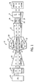
- FIG. 1 is a schematic flow diagram of an exemplary gas turbine engine 10 that includes a high-pressure turbine 12 and a low-pressure turbine 14.
- the gas turbine engine 10 may be employed within an aircraft, a watercraft, a locomotive, a power generation system, a mechanical drive, an oil-producing platform, a pipeline compressor, or combinations thereof.
- one or more components of the gas turbine engine 10 may comprise or may be constructed of CMCs that may provide higher temperature capability, thereby reducing cooling requirements of the gas turbine engine 10.
- the phrases "constructed of CMCs" and “comprised of CMCs” shall mean components substantially constructed of CMCs. More specifically, the CMC components shall include more CMC material than just a layer or coating of CMC materials.
- the components constructed of CMCs may be comprised or constructed substantially or entirely of CMC materials, including greater than about 50, 60, 70, 80, 90, or 100 percent CMC material.
- Combustion gases from the high-pressure turbine 12 may flow through a transition section 16 and continue to expand in the low-pressure turbine 14.
- the turbines 12 and 14 may be axially displaced and may be in fluid-dynamic communication, but mechanically disconnected to allow rotation at different speeds via concentric shafts.
- the high-pressure turbine 12 may rotate a shaft 18 to drive a compressor 20.
- the low-pressure turbine 14 may rotate a shaft 22 to drive a load 24.
- the load 24 may include a generator, a propeller, a transmission, a drive system, such as a load compressor, or combinations thereof.
- the load 24 may include a fan, such as a shrouded propeller, that directs air around the gas turbine engine 10 to increase the overall engine thrust.
- air may enter the gas turbine engine 10 through an intake section 26 and flow into the compressor 20, which compresses the air prior to entry into the combustor section 28.
- the combustor section 28 includes a combustor housing 30 disposed concentrically around the shafts 18 and 22 and located between the compressor 20 and the high-pressure turbine 12.
- the compressed air from the compressor 20 enters combustors 32 where the compressed air may mix and combust with fuel within the combustors 32 to drive the turbines 12 and 14.
- the hot combustion gases flow through the high-pressure turbine 12, driving the compressor 20 via the shaft 18.
- the hot combustion gases may then flow through the transition section 16 and into the low-pressure turbine 14, driving the load 24 via the shaft 22.
- the high-pressure turbine 12 and the low-pressure turbine 14 may rotate independently of each other.
- the transition section 16 may include a transition duct 33 for housing the combustion gases and a VATN assembly 34 for synchronizing the high-pressure turbine 12 and the low-pressure turbine 14.
- the VATN assembly 34 includes a plurality of VATNs disposed at multiple radial positions in an annular configuration about the shaft 22. Each VATN may be adjustable along its longitudinal axis to vary the angle of attack of the combustion gases entering the low-pressure turbine 14.
- each VATN may be rotated to modulate the flow of the combustion gases.
- the VATN assembly 34 may include variable area turbine nozzles or combinations of fixed and variable area turbine nozzles. After flowing through the VATN assembly 34 and the low-pressure turbine 14, the hot combustion gases may exit the gas turbine engine 10 through an exhaust section 36.
- the transition duct 33 and the VATN assembly 34 may be exposed to hot combustion gases flowing from the high-pressure turbine 12 to the low-pressure turbine 14.
- internal temperatures may reach 650 °C or higher which may make the components susceptible to creep, corrosion and/or high-cycle or low-cycle fatigue.
- certain components, such as the transition duct 33 and the VATN assembly 34 may be completely or partially constructed of CMCs to provide higher temperature capabilities.
- the higher temperature capabilities may allow for simplified cooling designs that may reduce manufacturing costs and sealing design requirements and/or allow for reduced cooling airflow, which may in turn increase the efficiency and output of the gas turbine engine 10.
- the higher temperature capabilities also may allow for reduced emissions of nitric oxide and nitrogen dioxide (collectively known as NOx) and carbon dioxide.
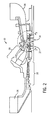
- FIG. 2 is a side view of an embodiment of the gas turbine engine 10 of FIG. 1 taken along the longitudinal axis.
- the gas turbine engine 10 includes the high-pressure turbine 12 and the low-pressure turbine 14. Air may enter through the air intake section 26 and be compressed by the compressor 20. The compressed air from the compressor 20 may then be directed into the combustor section 28 where the compressed air may be mixed with fuel gas or distillate, liquid fuel. The mixture of compressed air and fuel is generally burned within the combustor section 28 to generate a high-temperature, high-pressure combustion gas, which may be used to generate torque within the turbines 12 and 14. After flowing through the turbines 12 and 14, the combustion gas may exit the gas turbine engine 10 as exhaust gas through the exhaust section 36. As described above with respect to FIG. 1 , the shafts for the turbines 12 and 14 may not be mechanically connected to allow the turbines 12 and 14 to rotate at different speeds.
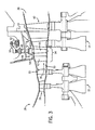
- FIG. 3 is a detailed sectional view of the transition section 16 and the turbines 12 and 14 shown in FIG. 2 .
- the high-pressure turbine 12 includes a bucket section 38 that may receive hot combustion gases from the combustor section 28. The hot combustion gases may flow through the bucket section 38 into the transition duct 33. Within the transition duct 33, the combustion gases may flow through the VATN assembly 34 and enter a bucket section 40 of the low-pressure turbine 14. The hot combustion gases may then exit through the exhaust section 36.
- the transition duct 33 may generally include a housing structure that fluid-dynamically couples the high-pressure turbine 12 to the low-pressure turbine 14 and provides a duct for combustion gases to flow between the turbines 12 and 14.
- the transition duct 33 may be constructed of a CMC, high temperature metallic alloy, or other suitable material.
- the VATN assembly 34 includes stationary airfoils 42 and variable airfoils 44.
- the airfoils 42 and 44 may each represent a plurality airfoils disposed radially within the transition duct 16 to direct the combustion gases from the transition duct into the bucket section 40 of the low-pressure turbine 14.
- the stationary airfoils 42 may remain in fixed positions, while the variable airfoils 44 may rotate along their longitudinal axes.
- Trunions 46 and 48 may be coupled to the airfoils 42 and 44, respectively, to support the airfoils 42 and 44.
- the trunions 48 also may be coupled to a drive lever 50 that may be actuated to rotate the airfoils 44 along their longitudinal axes to change the angle of attack of the combustion gases flowing through the transition duct 33 into the bucket section 40.
- the lever 50 also may be coupled to a synchronization ring 52 that may synchronize the movements of the variable airfoils 44.
- the airfoils 42 and 44 may include interior passageways for receiving a cooling fluid, such as air or steam.
- a cooling fluid such as air or steam.
- the airfoils 42 and 44 may receive a portion of compressed air bled from the compressor 20 ( FIG. 2 ).
- the cooling fluid may enter the airfoils 42 and 44 through flow passages 54 within the trunions 46.
- the flow passages 54 within the trunions 46 may be fluidly coupled to a manifold that supplies air bled from the compressor.
- the cooling fluid may flow through the flow passages 54 and into cooling passages within the individual airfoils 42 and/or 44.
- the flow passages 54 also may supply air to the transition duct 33.
- FIG. 4 is a perspective view of the VATN assembly 34.
- the fixed airfoils 42 are disposed between surfaces 56 and 58, and the variable airfoils 44 are disposed between surfaces 60 and 62. Together, the surfaces 56, 58, 60, and 62 may form the transition duct 33 ( FIG. 3 ). However, in other embodiments, additional structures may be disposed along the surfaces 56, 58, 60, and 62 to form the transition duct 33.
- the cooling air from the compressor may enter the fixed airfoils 42 through flow passages 54.
- ducts or manifolds may be provided to direct air from the flow passages 54 to cooling passages within the trunions 48 of the variable airfoils 44.
- the trunions 48 may include passageways for providing cooling fluid to the variable airfoils 44.
- seals may be provided around the flow passages 54. Seals also may be provided around the cooling passages and ducts configured to provide cooling fluid to the airfoils 44 as well as around the surfaces 60 and 62 that support the airfoils 44. For example, labyrinth and/or floating seals may be disposed around the surfaces 60 and 62 to impede entrainment of cooling fluid into the hot combustion gases flowing past the airfoils 42 and 44. The seals may be designed to impede the flow of cooling fluid into the transition duct 33 as the airfoils 44 rotate along their longitudinal axes between the surfaces 60 and 62.
- the airfoils 42 and 44 may be constructed of CMCs, which may provide greater thermal capabilities.
- Components of the transition duct 33 ( FIG. 3 ) also may be constructed of CMCs.
- the CMC materials for the transition duct 33 and the airfoils 42 and 44 may include any suitable type of fiber reinforced ceramic material.
- the CMC material may include fiber reinforced non-oxide ceramics, such as silicon carbide, silicon nitride, boron carbide, and aluminum nitride.
- the CMC material also may include fiber reinforced oxide matrix ceramics, such as alumina, silica, mullite, barium aluminosilicate, lithium aluminosilicate, or calcium aluminosilicate.
- the CMC materials may include combinations of oxide and non-oxide ceramics, as well as other suitable CMC materials.
- oxide ceramics may be used for certain components while non-oxide ceramics are used for other components.
- the CMC materials may include any suitable type of oxide or non-oxide reinforcing fibers, such as silicon carbide, carbon, glass, mullite, and alumina.
- the CMC material may provide higher thermal capabilities, thereby increasing the efficiency of the gas turbine engine.
- a silicon carbide-silicon carbide CMC component may be capable of withstanding temperatures from approximately 1204 °C to approximately 1316 °C.
- a carbon fiber -silicon carbide matrix CMC component may be capable of withstanding temperatures from approximately 1538 °C to approximately 2482 °C.
- the use of CMCs may facilitate reduced flow of cooling fluid within the airfoils.
- the CMCs also may simplify the design of seals used within the VATN assembly 34, and may simplify the geometry of the cooling passageways.
- other components of the airfoils such as trunions, synchronization rings, and levers also may be constructed of the CMCs to provide additional thermal cooling benefits.
- FIG. 5 is a perspective view of one of the variable airfoils 44 shown in FIG. 4 .
- the airfoil 44 includes a serpentine cooling passage 64.
- the VATN assembly 34 may receive a cooling fluid (arrow 66), such as air bled from the compressor, through an inlet port 68 disposed on the trunion 48 of the airfoil 44.
- the cooling fluid 66 may flow through the trunion flow passage 54 and enter the serpentine cooling passage 64 where the cooling fluid may flow through the interior of the airfoil 44 to cool the airfoil.
- the cooling fluid may exit the airfoil 44 through an outlet port 70.
- the cooling passage 64 is shown by way of example only and is not intended to limiting.
- the number of outlet ports may vary and the airfoils may include multiple separate cooling passages and/or angled passages.
- the airfoils may include cooling passages for convection cooling the inside of the airfoil, as well as internal impingement holes for impingement cooling inner surfaces of the airfoils.
- film-cooling holes may extend through the airfoil sidewalls to provide film cooling of external airfoil surfaces.
- the airfoil 44 may be constructed of a CMC material to reduce cooing flow within the cooling passage 64.
- the CMC material also may facilitate the use of simplified seals for impeding the flow of cooling fluid into the transition duct 33 ( FIG. 3 ).
- seals may be provided between the surfaces 60 and 72 to impede entrainment of cooling fluid during rotation of the airfoil 44. Seals also may be provided along the bottom surface 70 of the airfoil 44.
- the CMC material of the airfoil 44 may simplify the geometries of labyrinth seals and/or floating seals as well as other suitable seal types.
- FIG. 6 is an alternate embodiment of an airfoil 76 showing a simplified cooling passage 78 that may be provided for an airfoil 76 constructed of a CMC material.
- the CMC material may provide increased thermal capacity, thereby allowing simplified cooling passages to be used in addition to, or instead of, reduced flow of the cooling fluid 66.
- the cooling passage 78 includes a relatively straight-line geometry that may simplify manufacturing of the airfoil 76.
- the cooling fluid 66 may enter the airfoil 76 through the inlet 68, flow through the trunion flow passage 54, and cool the airfoil by flowing through the cooling passage 78.
- the cooling fluid 66 may exit through an outlet port 70.
- the use of the CMC material may reduce the number of outlet ports by 10-100 percent, and all subranges therebetween. More specifically, the number of outlet ports may be reduced by greater than 10, 20, 30, 40, 50, 60 70, 80, or 90 percent. Even more specifically, the use of the CMC material may reduce the number of outlet ports by 80-90 percent. Further, in certain embodiments, the CMC material may allow a reduction in the volume of cooling passages by 10-100 percent, and all subranges therebetween. For example, the CMC may allow a reduction in the volume of cooling passages by greater than 10, 20, 30, 40, 50, 60 70, 80, or 90 percent. More specifically, the volume of cooling passages may be reduced by 50-90 percent, or even more specifically by 80-90 percent.
- FIG. 7 illustrates another embodiment of a VATN airfoil 79 constructed of CMC material where no cooling passages are included.
- the use of the CMC material may eliminate the need for cooling passages due to the increased thermal capability of the CMC airfoil 79.
- the elimination of cooling passages also may eliminate the need for seals around the airfoil 79 and may eliminate the need for cooling fluid to be provided from the compressor, which in turn may increase the efficiency of the gas turbine engine.
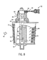
- FIG. 8 is a cut away sectional view of another embodiment of a VATN airfoil 80.
- Combustion gases (arrow 82) may flow past the airfoil 80.
- the gases may heat the airfoil.
- the airfoil 80 may be cooled by a cooling fluid 66 that may flow through the trunion flow passage 54 into cooling flow passages 84, 86, and 88 disposed within the interior volume of the airfoil 80.
- the flow passages are shown in a generally serpentine configuration that includes a flow passage 84 for providing cooling fluid to the section of the airfoil with a generally thicker cross-section.
- the flow passage 86 may cool the center section of the airfoil, and the flow passage 88 may provide cooling to the section of the airfoil with a generally thinner cross-section.
- the flow passages 84, 86, and 88 are provided by way of example and are not intended to be limiting.
- the number and geometry of cooling passages within the airfoil may vary.
- Several outlet ports 70 may allow the cooling fluid 66 to exit through outer surfaces of the airfoil 80 to provide film cooling for external airfoil surfaces.
- the airfoil 80 may be constructed of a CMC material allowing reduced flow of the cooling fluid 66.
- the CMC material may facilitate a reduction in the number of outlet ports 70.
- FIG. 8 depicts an alternate embodiment of a VATN airfoil 90 that includes approximately 80 percent fewer outlet ports 70 than shown in FIG. 8 .
- the reduction in the number of outlet ports may be possible due to the use of a CMC material to construct the airfoil.
- the use of a CMC material to construct the airfoil may facilitate other percentage reductions in outlet ports.
- the use of a CMC material may facilitate an approximately 10-100 percent reduction in outlet ports, and all subranges therebetween.
- CMC material may facilitate a reduction in outlet ports by greater than 10, 20, 30, 40, 50, 60, 70, 80, or 90 percent.
- other components of the airfoils such as trunions, synchronization rings, and levers also may be construction of the CMC material to provide additional cooling benefits.
- the CMC VATNs and transition ducts may find application in a variety of types of gas turbine engines.
- the CMC materials are particularly well-suited to gas turbine engines employing increased inlet combustion gas temperatures in order to increase operating efficiencies.
- the CMC materials also may be well-suited to gas turbine engines employing complex airfoil and/or transition duct geometries that may make incorporation of cooling passages difficult.
- the CMC materials may be used to construct airfoils used in various types of VATN assemblies.
- the VATN assemblies may include dual segment airfoils that have a stationary component and a variable component.
- the VATN assemblies also may include fixed airfoils, variable airfoils, or combinations thereof.
Landscapes
- Engineering & Computer Science (AREA)
- Mechanical Engineering (AREA)
- General Engineering & Computer Science (AREA)
- Chemical & Material Sciences (AREA)
- Materials Engineering (AREA)
- Combustion & Propulsion (AREA)
- Composite Materials (AREA)
- Ceramic Engineering (AREA)
- Turbine Rotor Nozzle Sealing (AREA)
- Control Of Turbines (AREA)
Applications Claiming Priority (1)
| Application Number | Priority Date | Filing Date | Title |
|---|---|---|---|
| US12/367,277 US8262345B2 (en) | 2009-02-06 | 2009-02-06 | Ceramic matrix composite turbine engine |
Publications (2)
| Publication Number | Publication Date |
|---|---|
| EP2216508A2 true EP2216508A2 (de) | 2010-08-11 |
| EP2216508A3 EP2216508A3 (de) | 2016-04-20 |
Family
ID=42102531
Family Applications (1)
| Application Number | Title | Priority Date | Filing Date |
|---|---|---|---|
| EP10152251.4A Withdrawn EP2216508A3 (de) | 2009-02-06 | 2010-02-01 | Turbinenleitstufe, Übergangskanal und Turbinentriebwerk aus Keramik-Matrix-Verbund |
Country Status (4)
| Country | Link |
|---|---|
| US (1) | US8262345B2 (de) |
| EP (1) | EP2216508A3 (de) |
| JP (1) | JP2010180878A (de) |
| CN (1) | CN101839152B (de) |
Cited By (5)
| Publication number | Priority date | Publication date | Assignee | Title |
|---|---|---|---|---|
| EP2787182A1 (de) * | 2013-04-02 | 2014-10-08 | MTU Aero Engines GmbH | Leitschaufel für eine Strömungsmaschine, Leitschaufelgitter und Verfahren zur Herstellung einer Leitschaufel oder eines Leitschaufelgitters |
| EP2578808A3 (de) * | 2011-10-05 | 2018-03-21 | General Electric Company | Turbinensystem mit einem Übergangskanal |
| EP2657460A3 (de) * | 2012-04-24 | 2018-04-25 | General Electric Company | Gasturbineneinlasssystem und Verfahren |
| EP3561237A1 (de) * | 2018-04-27 | 2019-10-30 | United Technologies Corporation | Verstellscahufelsystem mit kühlströmungsmodulation |
| EP3608506A1 (de) * | 2018-08-06 | 2020-02-12 | United Technologies Corporation | Gasturbinenleitschaufel welche einen zapfen mit kühlkanälen beinhaltet |
Families Citing this family (31)
| Publication number | Priority date | Publication date | Assignee | Title |
|---|---|---|---|---|
| US8702377B2 (en) * | 2010-06-23 | 2014-04-22 | Honeywell International Inc. | Gas turbine engine rotor tip clearance and shaft dynamics system and method |
| US8632297B2 (en) * | 2010-09-29 | 2014-01-21 | General Electric Company | Turbine airfoil and method for cooling a turbine airfoil |
| US20120301269A1 (en) * | 2011-05-26 | 2012-11-29 | Ioannis Alvanos | Clearance control with ceramic matrix composite rotor assembly for a gas turbine engine |
| US9938900B2 (en) | 2011-05-26 | 2018-04-10 | United Technologies Corporation | Ceramic matrix composite turbine exhaust case for a gas turbine engine |
| US8770931B2 (en) * | 2011-05-26 | 2014-07-08 | United Technologies Corporation | Hybrid Ceramic Matrix Composite vane structures for a gas turbine engine |
| US9039364B2 (en) * | 2011-06-29 | 2015-05-26 | United Technologies Corporation | Integrated case and stator |
| US20130089431A1 (en) * | 2011-10-07 | 2013-04-11 | General Electric Company | Airfoil for turbine system |
| US9273566B2 (en) * | 2012-06-22 | 2016-03-01 | United Technologies Corporation | Turbine engine variable area vane |
| US9587514B2 (en) * | 2012-07-13 | 2017-03-07 | United Technologies Corporation | Vane insertable tie rods with keyed connections |
| CA2879336A1 (en) | 2012-07-31 | 2014-04-17 | General Electric Company | Ceramic centerbody for an aircraft gas turbine engine and method of making |
| EP2946081B1 (de) | 2013-01-21 | 2017-06-07 | United Technologies Corporation | Schaufelanordnung mit variablem bereich für einen turbinenmotor |
| US10047629B2 (en) * | 2013-01-28 | 2018-08-14 | United Technologies Corporation | Multi-segment adjustable stator vane for a variable area vane arrangement |
| WO2014200831A1 (en) * | 2013-06-14 | 2014-12-18 | United Technologies Corporation | Variable area gas turbine engine component having movable spar and shell |
| WO2015069334A2 (en) * | 2013-08-07 | 2015-05-14 | United Technologies Corporation | Variable area turbine arrangement for a gas turbine engine |
| EP3907374B1 (de) * | 2013-08-21 | 2025-05-28 | RTX Corporation | Turbinenanordnung mit variabler fläche und sekundärströmungsmodulation |
| WO2015073242A1 (en) * | 2013-11-14 | 2015-05-21 | United Technologies Corporation | Airfoil contour for low-loss on-boarding of cooling air through an articulating spindle |
| US9644158B2 (en) | 2014-01-13 | 2017-05-09 | General Electric Company | Feed injector for a gasification system |
| US11448123B2 (en) * | 2014-06-13 | 2022-09-20 | Raytheon Technologies Corporation | Geared turbofan architecture |
| DE102014223975A1 (de) * | 2014-11-25 | 2016-05-25 | MTU Aero Engines AG | Leitschaufelkranz und Strömungsmaschine |
| US10767863B2 (en) | 2015-07-22 | 2020-09-08 | Rolls-Royce North American Technologies, Inc. | Combustor tile with monolithic inserts |
| US11230935B2 (en) | 2015-09-18 | 2022-01-25 | General Electric Company | Stator component cooling |
| US10590776B2 (en) * | 2016-06-06 | 2020-03-17 | General Electric Company | Turbine component and methods of making and cooling a turbine component |
| US20180016922A1 (en) * | 2016-07-12 | 2018-01-18 | Siemens Energy, Inc. | Transition Duct Support Arrangement for a Gas Turbine Engine |
| IT201700003996A1 (it) * | 2017-01-16 | 2018-07-16 | Nuovo Pignone Tecnologie Srl | Struttura galleggiante e metodo di funzionamento di una struttura galleggiante |
| US11118481B2 (en) | 2017-02-06 | 2021-09-14 | Raytheon Technologies Corporation | Ceramic matrix composite turbine exhaust assembly for a gas turbine engine |
| GB201813086D0 (en) | 2018-08-10 | 2018-09-26 | Rolls Royce Plc | Efficient gas turbine engine |
| GB201813082D0 (en) | 2018-08-10 | 2018-09-26 | Rolls Royce Plc | Efficient gas turbine engine |
| GB201813081D0 (en) | 2018-08-10 | 2018-09-26 | Rolls Royce Plc | Efficient gas turbine engine |
| US11326470B2 (en) * | 2019-12-20 | 2022-05-10 | General Electric Company | Ceramic matrix composite component including counterflow channels and method of producing |
| JP7431640B2 (ja) * | 2020-03-31 | 2024-02-15 | 川崎重工業株式会社 | ガスタービンエンジンのユニゾンリング |
| US20240426225A1 (en) * | 2023-06-26 | 2024-12-26 | Hamilton Sundstrand Corporation | Electrical actuation of variable stator vanes |
Family Cites Families (218)
| Publication number | Priority date | Publication date | Assignee | Title |
|---|---|---|---|---|
| US3604210A (en) | 1968-08-30 | 1971-09-14 | Rolls Royce | Gas turbine engine |
| GB1175037A (en) | 1968-09-11 | 1969-12-23 | Rolls Royce | Gas turbine jet propulsion engine |
| DE1931044A1 (de) | 1969-06-19 | 1971-03-11 | Motoren Turbinen Union | Leitgitter fuer Turbomaschinen mit verstellbaren Leitschaufeln |
| US3588269A (en) | 1969-06-25 | 1971-06-28 | Gen Motors Corp | Variable vane cascades |
| US3563669A (en) | 1969-07-10 | 1971-02-16 | Gen Motors Corp | Variable area nozzle |
| US3680309A (en) | 1969-09-25 | 1972-08-01 | Garrett Corp | Two-spool auxiliary power unit and control means |
| US3639076A (en) | 1970-05-28 | 1972-02-01 | Gen Electric | Constant power control system for gas turbine |
| US3638422A (en) | 1970-06-26 | 1972-02-01 | Gen Electric | Two-shaft gas turbine control system |
| US3674337A (en) | 1970-12-07 | 1972-07-04 | Bell Telephone Labor Inc | Beam coupling to and from thin film waveguide |
| US3719041A (en) | 1971-02-05 | 1973-03-06 | Secr Defence | Temperature-responsive control for gas turbine engines |
| US3719427A (en) | 1971-03-22 | 1973-03-06 | Caterpillar Tractor Co | Variable area nozzle for turbines or compressors |
| GB1381503A (en) | 1971-06-11 | 1975-01-22 | Rolls Royce | Variable area nozzle for a gas turbine engine |
| US3790298A (en) | 1972-05-01 | 1974-02-05 | Gen Electric | Flexible contour turbine nozzle for tight closure |
| US4169692A (en) | 1974-12-13 | 1979-10-02 | General Electric Company | Variable area turbine nozzle and means for sealing same |
| US4005572A (en) | 1975-04-18 | 1977-02-01 | Giffhorn William A | Gas turbine engine control system |
| US4025227A (en) | 1975-06-30 | 1977-05-24 | United Technologies Corporation | Variable area turbine |
| US3966352A (en) | 1975-06-30 | 1976-06-29 | United Technologies Corporation | Variable area turbine |
| US4003675A (en) | 1975-09-02 | 1977-01-18 | Caterpillar Tractor Co. | Actuating mechanism for gas turbine engine nozzles |
| US4053256A (en) | 1975-09-29 | 1977-10-11 | United Technologies Corporation | Variable camber vane for a gas turbine engine |
| JPS5277910A (en) * | 1975-12-23 | 1977-06-30 | Westinghouse Electric Corp | Blade equipment connecting 22shaft gas turbine compressor turbine and single stage power turbine |
| CA1040535A (en) | 1976-02-09 | 1978-10-17 | Westinghouse Electric Corporation | Variable vane and flowpath support assembly for a gas turbine |
| US4067661A (en) | 1976-10-01 | 1978-01-10 | Caterpillar Tractor Co. | Thermally compensated variable turbine nozzle position indicator |
| US4145875A (en) | 1976-10-15 | 1979-03-27 | General Motors Corporation | Variable flow capacity gas turbine engine for improved part load fuel economy |
| US4150915A (en) * | 1976-12-23 | 1979-04-24 | Caterpillar Tractor Co. | Variable geometry turbine nozzle |
| US4222235A (en) | 1977-07-25 | 1980-09-16 | General Electric Company | Variable cycle engine |
| US4193738A (en) | 1977-09-19 | 1980-03-18 | General Electric Company | Floating seal for a variable area turbine nozzle |
| US4214850A (en) | 1977-10-12 | 1980-07-29 | Ishikawajima-Harima Jukogyo Kabushiki Kaisha | Variable-capacity radial turbine |
| US4163629A (en) | 1977-12-23 | 1979-08-07 | The United States Of America As Represented By The Secretary Of The Air Force | Turbine vane construction |
| US4187054A (en) | 1978-04-20 | 1980-02-05 | General Electric Company | Turbine band cooling system |
| US4214851A (en) | 1978-04-20 | 1980-07-29 | General Electric Company | Structural cooling air manifold for a gas turbine engine |
| US4214852A (en) | 1978-04-20 | 1980-07-29 | General Electric Company | Variable turbine vane assembly |
| US4270344A (en) | 1978-05-19 | 1981-06-02 | General Motors Corporation | Hybrid dual shaft gas turbine with accumulator |
| US4173121A (en) | 1978-05-19 | 1979-11-06 | American Standard, Inc. | Hybrid dual shaft gas turbine with accumulator |
| US4264270A (en) | 1979-08-20 | 1981-04-28 | Carrier Corporation | Actuator for adjustable vane means of a turbomachine |
| US4406117A (en) | 1979-10-26 | 1983-09-27 | General Electric Company | Cyclic load duty control for gas turbine |
| GB2265668B (en) | 1981-02-28 | 1994-03-09 | Rolls Royce | Variable area nozzle for turbomachines |
| JPS5875902U (ja) * | 1981-11-16 | 1983-05-23 | 日産自動車株式会社 | ガスタ−ビン用可変ノズル |
| FR2529257A1 (fr) | 1982-06-28 | 1983-12-30 | Snecma | Volet de tuyere a structure composite carbone et acier |
| US5269139A (en) | 1991-06-28 | 1993-12-14 | The Boeing Company | Jet engine with noise suppressing mixing and exhaust sections |
| US5683225A (en) | 1991-10-28 | 1997-11-04 | General Electric Company | Jet engine variable area turbine nozzle |
| US5806052A (en) | 1992-07-06 | 1998-09-08 | General Electric Company | Fuzzy hierarchical controller for a turboshaft engine |
| US5355668A (en) * | 1993-01-29 | 1994-10-18 | General Electric Company | Catalyst-bearing component of gas turbine engine |
| US5517817A (en) | 1993-10-28 | 1996-05-21 | General Electric Company | Variable area turbine nozzle for turbine engines |
| GB2301868B (en) | 1995-06-05 | 1999-08-11 | Rolls Royce Plc | Improved actuator mechanism for variable angle vane arrays |
| GB9511269D0 (en) | 1995-06-05 | 1995-08-02 | Rolls Royce Plc | Variable angle vane arrays |
| US5879640A (en) * | 1995-08-16 | 1999-03-09 | Northrop Grumman Corporation | Ceramic catalytic converter |
| US5768884A (en) | 1995-11-22 | 1998-06-23 | General Electric Company | Gas turbine engine having flat rated horsepower |
| US5775092A (en) * | 1995-11-22 | 1998-07-07 | General Electric Company | Variable size gas turbine engine |
| JP2000502039A (ja) | 1995-12-15 | 2000-02-22 | ウエスチングハウス・エレクトリック・コーポレイション | 高温環境用の酸化物系セラミック複合材料、装置、方法及び構成材料 |
| JP2000517397A (ja) | 1996-09-04 | 2000-12-26 | シーメンス アクチエンゲゼルシヤフト | 高温ガス流に曝されるタービン翼 |
| US6930066B2 (en) | 2001-12-06 | 2005-08-16 | Siemens Westinghouse Power Corporation | Highly defective oxides as sinter resistant thermal barrier coating |
| US6258467B1 (en) | 2000-08-17 | 2001-07-10 | Siemens Westinghouse Power Corporation | Thermal barrier coating having high phase stability |
| US5911679A (en) * | 1996-12-31 | 1999-06-15 | General Electric Company | Variable pitch rotor assembly for a gas turbine engine inlet |
| US5931636A (en) * | 1997-08-28 | 1999-08-03 | General Electric Company | Variable area turbine nozzle |
| US5941537A (en) | 1997-09-05 | 1999-08-24 | General Eletric Company | Pressure actuated static seal |
| US6517959B1 (en) | 1997-11-03 | 2003-02-11 | Siemens Aktiengesellschaft | Product designed to be subjected to the effects of hot gas and method for producing a coating for this product |
| US6111599A (en) | 1998-01-14 | 2000-08-29 | Westinghouse Savannah River Company | Apparatus for observing a hostile environment |
| US7179524B2 (en) * | 1998-03-27 | 2007-02-20 | Siemens Power Generation, Inc. | Insulated ceramic matrix composite and method of manufacturing |
| US6676783B1 (en) | 1998-03-27 | 2004-01-13 | Siemens Westinghouse Power Corporation | High temperature insulation for ceramic matrix composites |
| US7563504B2 (en) | 1998-03-27 | 2009-07-21 | Siemens Energy, Inc. | Utilization of discontinuous fibers for improving properties of high temperature insulation of ceramic matrix composites |
| US6641907B1 (en) | 1999-12-20 | 2003-11-04 | Siemens Westinghouse Power Corporation | High temperature erosion resistant coating and material containing compacted hollow geometric shapes |
| US6977060B1 (en) | 2000-03-28 | 2005-12-20 | Siemens Westinghouse Power Corporation | Method for making a high temperature erosion resistant coating and material containing compacted hollow geometric shapes |
| US6197424B1 (en) * | 1998-03-27 | 2001-03-06 | Siemens Westinghouse Power Corporation | Use of high temperature insulation for ceramic matrix composites in gas turbines |
| US6733907B2 (en) | 1998-03-27 | 2004-05-11 | Siemens Westinghouse Power Corporation | Hybrid ceramic material composed of insulating and structural ceramic layers |
| US6013592A (en) | 1998-03-27 | 2000-01-11 | Siemens Westinghouse Power Corporation | High temperature insulation for ceramic matrix composites |
| US7067181B2 (en) | 2003-08-05 | 2006-06-27 | Siemens Power Generation, Inc. | Insulating ceramic based on partially filled shapes |
| US6092361A (en) | 1998-05-29 | 2000-07-25 | Pratt & Whitney Canada Corp. | Recuperator for gas turbine engine |
| US6190133B1 (en) | 1998-08-14 | 2001-02-20 | Allison Engine Company | High stiffness airoil and method of manufacture |
| DE59907046D1 (de) | 1998-10-22 | 2003-10-23 | Siemens Ag | Erzeugnis mit wärmedämmschicht sowie verfahren zur herstellung einer wärmedämmschicht |
| US6099252A (en) | 1998-11-16 | 2000-08-08 | General Electric Company | Axial serpentine cooled airfoil |
| US6274078B1 (en) * | 1999-01-27 | 2001-08-14 | General Electric Company | Method of removing cores from ceramic matrix composite articles |
| JP2000247745A (ja) * | 1999-02-26 | 2000-09-12 | Toshiba Corp | セラミックス基繊維複合材料、その製造方法およびガスタービン部品 |
| US6235370B1 (en) | 1999-03-03 | 2001-05-22 | Siemens Westinghouse Power Corporation | High temperature erosion resistant, abradable thermal barrier composite coating |
| GB9911867D0 (en) | 1999-05-22 | 1999-07-21 | Rolls Royce Plc | A combustion chamber assembly and a method of operating a combustion chamber assembly |
| GB9911871D0 (en) | 1999-05-22 | 1999-07-21 | Rolls Royce Plc | A gas turbine engine and a method of controlling a gas turbine engine |
| US6305156B1 (en) | 1999-09-03 | 2001-10-23 | Alliedsignal Inc. | Integrated bleed air and engine starting system |
| US20080101683A1 (en) | 1999-12-22 | 2008-05-01 | Siemens Power Generation, Inc. | System and method of evaluating uncoated turbine engine components |
| EP1126221A1 (de) | 2000-02-17 | 2001-08-22 | Siemens Aktiengesellschaft | Gepolsterter Hitzeschildstein zur Auskleidung einer Gasturbinenbrennkammerwand |
| US6325593B1 (en) * | 2000-02-18 | 2001-12-04 | General Electric Company | Ceramic turbine airfoils with cooled trailing edge blocks |
| US6441341B1 (en) * | 2000-06-16 | 2002-08-27 | General Electric Company | Method of forming cooling holes in a ceramic matrix composite turbine components |
| US6528190B1 (en) * | 2000-08-02 | 2003-03-04 | Siemens Westinghouse Power Corporation | Fiber coating compounds for reinforced ceramic matrix composites |
| US6670046B1 (en) | 2000-08-31 | 2003-12-30 | Siemens Westinghouse Power Corporation | Thermal barrier coating system for turbine components |
| US6514046B1 (en) | 2000-09-29 | 2003-02-04 | Siemens Westinghouse Power Corporation | Ceramic composite vane with metallic substructure |
| US6512379B2 (en) | 2001-02-05 | 2003-01-28 | Siemens Westinghouse Power Corporation | Condition monitoring of turbine blades and vanes in service |
| US6939603B2 (en) | 2001-03-22 | 2005-09-06 | Siemens Westinghouse Power Corporation | Thermal barrier coating having subsurface inclusions for improved thermal shock resistance |
| GB0108398D0 (en) | 2001-04-04 | 2001-05-23 | Siemens Ag | Seal element for sealing a gap and combustion turbine having a seal element |
| SE520272C2 (sv) * | 2001-04-06 | 2003-06-17 | Volvo Aero Corp | Motorbromssystem för en gasturbin samt förfarande för motorbromsning av en gasturbin |
| US6751940B1 (en) | 2001-05-08 | 2004-06-22 | Marius Paul | High efficiency gas turbine power generator |
| US6617013B2 (en) | 2001-05-10 | 2003-09-09 | Siemens Westinghouse Power Corporation | Ceramic matrix composite having improved interlaminar strength |
| US6516603B1 (en) | 2001-06-06 | 2003-02-11 | The United States Of America As Represented By The Secretary Of The Navy | Gas turbine engine system with water injection |
| ITTO20010704A1 (it) | 2001-07-18 | 2003-01-18 | Fiatavio Spa | Paletta a doppia parete per una turbina, particolarmente per applicazioni aeronautiche. |
| US6703137B2 (en) | 2001-08-02 | 2004-03-09 | Siemens Westinghouse Power Corporation | Segmented thermal barrier coating and method of manufacturing the same |
| US6602053B2 (en) | 2001-08-02 | 2003-08-05 | Siemens Westinghouse Power Corporation | Cooling structure and method of manufacturing the same |
| US7080513B2 (en) | 2001-08-04 | 2006-07-25 | Siemens Aktiengesellschaft | Seal element for sealing a gap and combustion turbine having a seal element |
| US7001679B2 (en) | 2001-08-09 | 2006-02-21 | Siemens Westinghouse Power Corporation | Protective overlayer for ceramics |
| US6554563B2 (en) * | 2001-08-13 | 2003-04-29 | General Electric Company | Tangential flow baffle |
| US6746755B2 (en) * | 2001-09-24 | 2004-06-08 | Siemens Westinghouse Power Corporation | Ceramic matrix composite structure having integral cooling passages and method of manufacture |
| US7541005B2 (en) | 2001-09-26 | 2009-06-02 | Siemens Energy Inc. | Catalytic thermal barrier coatings |
| US7017415B2 (en) | 2001-09-27 | 2006-03-28 | Siemens Westinghouse Power Corporation | Apparatus for sensing pressure fluctuations in a hostile environment |
| US6884384B2 (en) | 2001-09-27 | 2005-04-26 | Siemens Westinghouse Power Corporation | Method for making a high temperature erosion resistant material containing compacted hollow geometric shapes |
| JP4166977B2 (ja) * | 2001-12-17 | 2008-10-15 | 三菱重工業株式会社 | 耐高温腐食合金材、遮熱コーティング材、タービン部材、及びガスタービン |
| DE60105830T2 (de) | 2001-12-21 | 2006-03-09 | Siemens Ag | Verfahren zum Entfernen einer Metallschicht eines Schichtsystems |
| EP1329592A1 (de) | 2002-01-18 | 2003-07-23 | Siemens Aktiengesellschaft | Turbine mit mindestens vier Stufen und Verwendung einer Turbinenschaufel mit verringerter Masse |
| US6677064B1 (en) | 2002-05-29 | 2004-01-13 | Siemens Westinghouse Power Corporation | In-situ formation of multiphase deposited thermal barrier coatings |
| US6709230B2 (en) * | 2002-05-31 | 2004-03-23 | Siemens Westinghouse Power Corporation | Ceramic matrix composite gas turbine vane |
| US6648597B1 (en) | 2002-05-31 | 2003-11-18 | Siemens Westinghouse Power Corporation | Ceramic matrix composite turbine vane |
| ITTO20020699A1 (it) | 2002-08-06 | 2004-02-07 | Fiatavio Spa | Paletta per lo statore di una turbina a geometria variabile, |
| US6929852B2 (en) | 2002-08-08 | 2005-08-16 | Siemens Westinghouse Power Corporation | Protective overlayer for ceramics |
| JP4392349B2 (ja) | 2002-08-28 | 2009-12-24 | ウェイン・ステイト・ユニバーシティ | 音波赤外線画像化における多重モード可撓性励起及び音響カオスのためのシステム及び方法 |
| US7291407B2 (en) | 2002-09-06 | 2007-11-06 | Siemens Power Generation, Inc. | Ceramic material having ceramic matrix composite backing and method of manufacturing |
| US6758653B2 (en) | 2002-09-09 | 2004-07-06 | Siemens Westinghouse Power Corporation | Ceramic matrix composite component for a gas turbine engine |
| US7093359B2 (en) | 2002-09-17 | 2006-08-22 | Siemens Westinghouse Power Corporation | Composite structure formed by CMC-on-insulation process |
| US9068464B2 (en) | 2002-09-17 | 2015-06-30 | Siemens Energy, Inc. | Method of joining ceramic parts and articles so formed |
| US7582359B2 (en) | 2002-09-23 | 2009-09-01 | Siemens Energy, Inc. | Apparatus and method of monitoring operating parameters of a gas turbine |
| US6838157B2 (en) | 2002-09-23 | 2005-01-04 | Siemens Westinghouse Power Corporation | Method and apparatus for instrumenting a gas turbine component having a barrier coating |
| US7618712B2 (en) | 2002-09-23 | 2009-11-17 | Siemens Energy, Inc. | Apparatus and method of detecting wear in an abradable coating system |
| US7572524B2 (en) | 2002-09-23 | 2009-08-11 | Siemens Energy, Inc. | Method of instrumenting a component |
| US20050198967A1 (en) | 2002-09-23 | 2005-09-15 | Siemens Westinghouse Power Corp. | Smart component for use in an operating environment |
| US7270890B2 (en) | 2002-09-23 | 2007-09-18 | Siemens Power Generation, Inc. | Wear monitoring system with embedded conductors |
| US6767659B1 (en) | 2003-02-27 | 2004-07-27 | Siemens Westinghouse Power Corporation | Backside radiative cooled ceramic matrix composite component |
| EP1464723B1 (de) | 2003-04-04 | 2018-02-21 | Siemens Energy, Inc. | Wärmedämmschicht mit nanometrischen Eigenschaften |
| US7311790B2 (en) | 2003-04-25 | 2007-12-25 | Siemens Power Generation, Inc. | Hybrid structure using ceramic tiles and method of manufacture |
| US7198860B2 (en) | 2003-04-25 | 2007-04-03 | Siemens Power Generation, Inc. | Ceramic tile insulation for gas turbine component |
| US6984277B2 (en) | 2003-07-31 | 2006-01-10 | Siemens Westinghouse Power Corporation | Bond enhancement for thermally insulated ceramic matrix composite materials |
| US7108925B2 (en) | 2003-09-22 | 2006-09-19 | Siemens Power Generation, Inc. | High temperature insulation utilizing zirconia-hafnia |
| US6938404B2 (en) | 2003-09-23 | 2005-09-06 | Rrc-Sgte Technologies, Llc | Supercharged open cycle gas turbine engine |
| DE50306521D1 (de) | 2003-10-02 | 2007-03-29 | Siemens Ag | Schichtsystem und Verfahren zur Herstellung eines Schichtsystems |
| US6929445B2 (en) * | 2003-10-22 | 2005-08-16 | General Electric Company | Split flow turbine nozzle |
| EP1528343A1 (de) | 2003-10-27 | 2005-05-04 | Siemens Aktiengesellschaft | Keramischer Hitzeschildstein mit eingebetteten Verstärkungselementen zur Auskleidung einer Gasturbinenbrennkammerwand |
| US6942203B2 (en) | 2003-11-04 | 2005-09-13 | General Electric Company | Spring mass damper system for turbine shrouds |
| EP1533113A1 (de) | 2003-11-14 | 2005-05-25 | Siemens Aktiengesellschaft | Hochtemperatur-Schichtsystem zur Wärmeableitung und Verfahren zu dessen Herstellung |
| US6981841B2 (en) | 2003-11-20 | 2006-01-03 | General Electric Company | Triple circuit turbine cooling |
| US7044709B2 (en) | 2004-01-15 | 2006-05-16 | General Electric Company | Methods and apparatus for coupling ceramic matrix composite turbine components |
| US20050158171A1 (en) | 2004-01-15 | 2005-07-21 | General Electric Company | Hybrid ceramic matrix composite turbine blades for improved processibility and performance |
| US7351364B2 (en) | 2004-01-29 | 2008-04-01 | Siemens Power Generation, Inc. | Method of manufacturing a hybrid structure |
| US7687016B1 (en) * | 2004-02-13 | 2010-03-30 | The United States Of America As Represented By The Administrator Of National Aeronautics And Space Administration | Methods for producing silicon carbide architectural preforms |
| US7306826B2 (en) | 2004-02-23 | 2007-12-11 | General Electric Company | Use of biased fabric to improve properties of SiC/SiC ceramic composites for turbine engine components |
| US7509735B2 (en) | 2004-04-22 | 2009-03-31 | Siemens Energy, Inc. | In-frame repairing system of gas turbine components |
| US7066717B2 (en) | 2004-04-22 | 2006-06-27 | Siemens Power Generation, Inc. | Ceramic matrix composite airfoil trailing edge arrangement |
| US7334330B2 (en) | 2004-04-28 | 2008-02-26 | Siemens Power Generation, Inc. | Thermally insulating layer incorporating a distinguishing agent and method for inspecting the same |
| US7197879B2 (en) | 2004-04-29 | 2007-04-03 | Honeywell International, Inc. | Multiple electric fuel metering systems for gas turbine applications |
| US7353647B2 (en) * | 2004-05-13 | 2008-04-08 | General Electric Company | Methods and apparatus for assembling gas turbine engines |
| EP1645653A1 (de) | 2004-10-07 | 2006-04-12 | Siemens Aktiengesellschaft | Schichtsystem |
| JP4020905B2 (ja) * | 2004-10-27 | 2007-12-12 | 川崎重工業株式会社 | タービンノズルの両持型支持構造 |
| ES2360960T3 (es) | 2004-11-04 | 2011-06-10 | Feyecon B.V. | Método de coloración de un sustrato con una sustancia de coloración reactiva en dióxido de carbono supercrítico o casi supercrítico. |
| US7237389B2 (en) | 2004-11-18 | 2007-07-03 | Siemens Power Generation, Inc. | Attachment system for ceramic combustor liner |
| EP1739356A1 (de) | 2005-07-01 | 2007-01-03 | Siemens Aktiengesellschaft | Formmasse zum Herstellen einer feuerfesten Auskleidung |
| US7153096B2 (en) | 2004-12-02 | 2006-12-26 | Siemens Power Generation, Inc. | Stacked laminate CMC turbine vane |
| US7255535B2 (en) | 2004-12-02 | 2007-08-14 | Albrecht Harry A | Cooling systems for stacked laminate CMC vane |
| US7402347B2 (en) | 2004-12-02 | 2008-07-22 | Siemens Power Generation, Inc. | In-situ formed thermal barrier coating for a ceramic component |
| US7247002B2 (en) | 2004-12-02 | 2007-07-24 | Siemens Power Generation, Inc. | Lamellate CMC structure with interlock to metallic support structure |
| US7247003B2 (en) | 2004-12-02 | 2007-07-24 | Siemens Power Generation, Inc. | Stacked lamellate assembly |
| US7198458B2 (en) | 2004-12-02 | 2007-04-03 | Siemens Power Generation, Inc. | Fail safe cooling system for turbine vanes |
| US7123031B2 (en) | 2004-12-20 | 2006-10-17 | Siemens Power Generation, Inc. | System for on-line assessment of the condition of thermal coating on a turbine vane |
| US7223465B2 (en) | 2004-12-29 | 2007-05-29 | General Electric Company | SiC/SiC composites incorporating uncoated fibers to improve interlaminar strength |
| US7435058B2 (en) * | 2005-01-18 | 2008-10-14 | Siemens Power Generation, Inc. | Ceramic matrix composite vane with chordwise stiffener |
| US7258530B2 (en) | 2005-01-21 | 2007-08-21 | Siemens Power Generation, Inc. | CMC component and method of fabrication |
| US7217088B2 (en) | 2005-02-02 | 2007-05-15 | Siemens Power Generation, Inc. | Cooling fluid preheating system for an airfoil in a turbine engine |
| US7341428B2 (en) | 2005-02-02 | 2008-03-11 | Siemens Power Generation, Inc. | Turbine blade for monitoring torsional blade vibration |
| US7326030B2 (en) * | 2005-02-02 | 2008-02-05 | Siemens Power Generation, Inc. | Support system for a composite airfoil in a turbine engine |
| US7387758B2 (en) | 2005-02-16 | 2008-06-17 | Siemens Power Generation, Inc. | Tabbed ceramic article for improved interlaminar strength |
| US7176681B2 (en) | 2005-03-08 | 2007-02-13 | Siemens Power Generation, Inc. | Inspection of composite components using magnetic resonance imaging |
| US7300621B2 (en) | 2005-03-16 | 2007-11-27 | Siemens Power Generation, Inc. | Method of making a ceramic matrix composite utilizing partially stabilized fibers |
| US7230205B2 (en) | 2005-03-29 | 2007-06-12 | Siemens Power Generation, Inc. | Compressor airfoil surface wetting and icing detection system |
| US20060225432A1 (en) | 2005-03-29 | 2006-10-12 | Awdalla Essam T | Supercharged open cycle gas turbine engine |
| US7452182B2 (en) * | 2005-04-07 | 2008-11-18 | Siemens Energy, Inc. | Multi-piece turbine vane assembly |
| US7316539B2 (en) | 2005-04-07 | 2008-01-08 | Siemens Power Generation, Inc. | Vane assembly with metal trailing edge segment |
| FR2885114B1 (fr) | 2005-04-28 | 2007-06-08 | Airbus France Sas | Aeronef a faible bruit, notamment lors des decollages et des atterrissages |
| US7442444B2 (en) * | 2005-06-13 | 2008-10-28 | General Electric Company | Bond coat for silicon-containing substrate for EBC and processes for preparing same |
| US7393183B2 (en) | 2005-06-17 | 2008-07-01 | Siemens Power Generation, Inc. | Trailing edge attachment for composite airfoil |
| US7754126B2 (en) | 2005-06-17 | 2010-07-13 | General Electric Company | Interlaminar tensile reinforcement of SiC/SiC CMC's using fugitive fibers |
| US7549840B2 (en) | 2005-06-17 | 2009-06-23 | General Electric Company | Through thickness reinforcement of SiC/SiC CMC's through in-situ matrix plugs manufactured using fugitive fibers |
| US7494317B2 (en) | 2005-06-23 | 2009-02-24 | Siemens Energy, Inc. | Ring seal attachment system |
| US7721547B2 (en) * | 2005-06-27 | 2010-05-25 | Siemens Energy, Inc. | Combustion transition duct providing stage 1 tangential turning for turbine engines |
| US7375543B2 (en) | 2005-07-21 | 2008-05-20 | Lsi Corporation | Electrostatic discharge testing |
| CA2616475C (en) * | 2005-07-25 | 2011-03-29 | Siemens Power Generation, Inc. | Method of forming cmc component |
| US7563071B2 (en) | 2005-08-04 | 2009-07-21 | Siemens Energy, Inc. | Pin-loaded mounting apparatus for a refractory component in a combustion turbine engine |
| US7785076B2 (en) | 2005-08-30 | 2010-08-31 | Siemens Energy, Inc. | Refractory component with ceramic matrix composite skeleton |
| US7329087B2 (en) | 2005-09-19 | 2008-02-12 | General Electric Company | Seal-less CMC vane to platform interfaces |
| US20070075455A1 (en) | 2005-10-04 | 2007-04-05 | Siemens Power Generation, Inc. | Method of sealing a free edge of a composite material |
| US7278820B2 (en) | 2005-10-04 | 2007-10-09 | Siemens Power Generation, Inc. | Ring seal system with reduced cooling requirements |
| US7546743B2 (en) | 2005-10-12 | 2009-06-16 | General Electric Company | Bolting configuration for joining ceramic combustor liner to metal mounting attachments |
| US20070096371A1 (en) | 2005-10-27 | 2007-05-03 | General Electric Company | Process of producing ceramic matrix composites |
| US7238002B2 (en) | 2005-11-03 | 2007-07-03 | General Electric Company | Damper seal system and method |
| ATE469110T1 (de) | 2005-11-21 | 2010-06-15 | Siemens Ag | Verfahren zum herstellen eines gebrannten formteils einer feuerfesten auskleidung |
| US20070128447A1 (en) | 2005-12-02 | 2007-06-07 | General Electric Company | Corrosion inhibiting ceramic coating and method of application |
| US7510777B2 (en) | 2005-12-16 | 2009-03-31 | General Electric Company | Composite thermal barrier coating with improved impact and erosion resistance |
| US7754342B2 (en) | 2005-12-19 | 2010-07-13 | General Electric Company | Strain tolerant corrosion protecting coating and spray method of application |
| US7481621B2 (en) | 2005-12-22 | 2009-01-27 | Siemens Energy, Inc. | Airfoil with heating source |
| US7371043B2 (en) | 2006-01-12 | 2008-05-13 | Siemens Power Generation, Inc. | CMC turbine shroud ring segment and fabrication method |
| US7513738B2 (en) * | 2006-02-15 | 2009-04-07 | General Electric Company | Methods and apparatus for cooling gas turbine rotor blades |
| US7507466B2 (en) | 2006-02-22 | 2009-03-24 | General Electric Company | Manufacture of CMC articles having small complex features |
| US7836677B2 (en) * | 2006-04-07 | 2010-11-23 | Siemens Energy, Inc. | At least one combustion apparatus and duct structure for a gas turbine engine |
| US7604456B2 (en) | 2006-04-11 | 2009-10-20 | Siemens Energy, Inc. | Vane shroud through-flow platform cover |
| US7534086B2 (en) | 2006-05-05 | 2009-05-19 | Siemens Energy, Inc. | Multi-layer ring seal |
| US20100257733A1 (en) * | 2006-07-20 | 2010-10-14 | Honeywell International, Inc. | High pressure single crystal turbine blade tip repair with laser cladding |
| US20080025838A1 (en) | 2006-07-25 | 2008-01-31 | Siemens Power Generation, Inc. | Ring seal for a turbine engine |
| US7600978B2 (en) | 2006-07-27 | 2009-10-13 | Siemens Energy, Inc. | Hollow CMC airfoil with internal stitch |
| US7488157B2 (en) | 2006-07-27 | 2009-02-10 | Siemens Energy, Inc. | Turbine vane with removable platform inserts |
| US7631499B2 (en) | 2006-08-03 | 2009-12-15 | Siemens Energy, Inc. | Axially staged combustion system for a gas turbine engine |
| EP1903184B1 (de) | 2006-09-21 | 2019-05-01 | Siemens Energy, Inc. | Subsystem einer Verbrennungsturbine mit verwundenem Übergangskanal |
| US7950234B2 (en) | 2006-10-13 | 2011-05-31 | Siemens Energy, Inc. | Ceramic matrix composite turbine engine components with unitary stiffening frame |
| US7686577B2 (en) | 2006-11-02 | 2010-03-30 | Siemens Energy, Inc. | Stacked laminate fiber wrapped segment |
| US7600979B2 (en) | 2006-11-28 | 2009-10-13 | General Electric Company | CMC articles having small complex features |
| US20080199661A1 (en) | 2007-02-15 | 2008-08-21 | Siemens Power Generation, Inc. | Thermally insulated CMC structure with internal cooling |
| US7798769B2 (en) | 2007-02-15 | 2010-09-21 | Siemens Energy, Inc. | Flexible, high-temperature ceramic seal element |
| US20080207075A1 (en) | 2007-02-22 | 2008-08-28 | Siemens Power Generation, Inc. | Optimized fabric lay-up for improved ceramic matrix composites |
| US20080206542A1 (en) | 2007-02-22 | 2008-08-28 | Siemens Power Generation, Inc. | Ceramic matrix composite abradable via reduction of surface area |
| US7887300B2 (en) | 2007-02-27 | 2011-02-15 | Siemens Energy, Inc. | CMC airfoil with thin trailing edge |
| US20090211260A1 (en) * | 2007-05-03 | 2009-08-27 | Brayton Energy, Llc | Multi-Spool Intercooled Recuperated Gas Turbine |
| US20090067978A1 (en) * | 2007-05-24 | 2009-03-12 | Suljak Jr George T | Variable area turbine vane arrangement |
| JP2009013837A (ja) * | 2007-07-03 | 2009-01-22 | Hitachi Ltd | ガスタービン設備 |
| US7963745B1 (en) * | 2007-07-10 | 2011-06-21 | Florida Turbine Technologies, Inc. | Composite turbine blade |
| US8202043B2 (en) * | 2007-10-15 | 2012-06-19 | United Technologies Corp. | Gas turbine engines and related systems involving variable vanes |
| US8105019B2 (en) * | 2007-12-10 | 2012-01-31 | United Technologies Corporation | 3D contoured vane endwall for variable area turbine vane arrangement |
| US8408874B2 (en) * | 2008-04-11 | 2013-04-02 | United Technologies Corporation | Platformless turbine blade |
| US8096758B2 (en) * | 2008-09-03 | 2012-01-17 | Siemens Energy, Inc. | Circumferential shroud inserts for a gas turbine vane platform |
| US8251652B2 (en) * | 2008-09-18 | 2012-08-28 | Siemens Energy, Inc. | Gas turbine vane platform element |
-
2009
- 2009-02-06 US US12/367,277 patent/US8262345B2/en not_active Expired - Fee Related
-
2010
- 2010-02-01 EP EP10152251.4A patent/EP2216508A3/de not_active Withdrawn
- 2010-02-02 JP JP2010020799A patent/JP2010180878A/ja active Pending
- 2010-02-03 CN CN201010119102.7A patent/CN101839152B/zh not_active Expired - Fee Related
Non-Patent Citations (1)
| Title |
|---|
| None |
Cited By (8)
| Publication number | Priority date | Publication date | Assignee | Title |
|---|---|---|---|---|
| EP2578808A3 (de) * | 2011-10-05 | 2018-03-21 | General Electric Company | Turbinensystem mit einem Übergangskanal |
| EP2657460A3 (de) * | 2012-04-24 | 2018-04-25 | General Electric Company | Gasturbineneinlasssystem und Verfahren |
| EP2787182A1 (de) * | 2013-04-02 | 2014-10-08 | MTU Aero Engines GmbH | Leitschaufel für eine Strömungsmaschine, Leitschaufelgitter und Verfahren zur Herstellung einer Leitschaufel oder eines Leitschaufelgitters |
| US10060439B2 (en) | 2013-04-02 | 2018-08-28 | MTU Aero Engines AG | Guide vane for a turbomachine, guide vane cascade, and method for manufacturing a guide vane or a guide vane cascade |
| EP3561237A1 (de) * | 2018-04-27 | 2019-10-30 | United Technologies Corporation | Verstellscahufelsystem mit kühlströmungsmodulation |
| US10619509B2 (en) | 2018-04-27 | 2020-04-14 | United Technologies Corporation | Gas turbine engine flow modulation in a rotating vane |
| EP3608506A1 (de) * | 2018-08-06 | 2020-02-12 | United Technologies Corporation | Gasturbinenleitschaufel welche einen zapfen mit kühlkanälen beinhaltet |
| US11668202B2 (en) | 2018-08-06 | 2023-06-06 | Raytheon Technologies Corporation | Airfoil core inlets in a rotating vane |
Also Published As
| Publication number | Publication date |
|---|---|
| CN101839152B (zh) | 2016-05-18 |
| CN101839152A (zh) | 2010-09-22 |
| US20100202873A1 (en) | 2010-08-12 |
| US8262345B2 (en) | 2012-09-11 |
| EP2216508A3 (de) | 2016-04-20 |
| JP2010180878A (ja) | 2010-08-19 |
Similar Documents
| Publication | Publication Date | Title |
|---|---|---|
| US8262345B2 (en) | Ceramic matrix composite turbine engine | |
| US11143106B2 (en) | Combustion section heat transfer system for a propulsion system | |
| US11781448B1 (en) | Shroud pin for gas turbine engine shroud | |
| CN106014493B (zh) | 用于冷却涡轮发动机的系统 | |
| US8382436B2 (en) | Non-integral turbine blade platforms and systems | |
| US20180216575A1 (en) | Cool core gas turbine engine | |
| US12078107B2 (en) | Gas turbine engine | |
| US12535037B2 (en) | Gas turbine engine | |
| US20250369395A1 (en) | Gas turbine engine | |
| US20250198290A1 (en) | Gas turbine engine | |
| US20170260873A1 (en) | System and method for cooling trailing edge and/or leading edge of hot gas flow path component | |
| CN107035436A (zh) | 用于冷却涡轮护罩的系统和方法 | |
| US11067277B2 (en) | Component assembly for a gas turbine engine | |
| US11674403B2 (en) | Annular shroud assembly | |
| US11220921B2 (en) | Vane assembly | |
| US12428992B2 (en) | Gas turbine engine | |
| US20250257686A1 (en) | Gas turbine engine | |
| US12428962B1 (en) | Gas turbine engine with acoustic spacing of the fan blades and outlet guide vanes | |
| US20250257687A1 (en) | Gas turbine engine | |
| EP4365428A1 (de) | Gasturbinentriebwerk | |
| US12168960B2 (en) | Gas turbine engine | |
| US20250243812A1 (en) | Gas turbine engine | |
| US20260015974A1 (en) | Gas turbine engine |
Legal Events
| Date | Code | Title | Description |
|---|---|---|---|
| PUAI | Public reference made under article 153(3) epc to a published international application that has entered the european phase |
Free format text: ORIGINAL CODE: 0009012 |
|
| AK | Designated contracting states |
Kind code of ref document: A2 Designated state(s): AT BE BG CH CY CZ DE DK EE ES FI FR GB GR HR HU IE IS IT LI LT LU LV MC MK MT NL NO PL PT RO SE SI SK SM TR |
|
| PUAL | Search report despatched |
Free format text: ORIGINAL CODE: 0009013 |
|
| AK | Designated contracting states |
Kind code of ref document: A3 Designated state(s): AT BE BG CH CY CZ DE DK EE ES FI FR GB GR HR HU IE IS IT LI LT LU LV MC MK MT NL NO PL PT RO SE SI SK SM TR |
|
| RIC1 | Information provided on ipc code assigned before grant |
Ipc: F01D 5/18 20060101AFI20160316BHEP Ipc: F04D 27/02 20060101ALI20160316BHEP Ipc: F01D 5/28 20060101ALI20160316BHEP Ipc: F01D 17/16 20060101ALI20160316BHEP Ipc: F04D 29/56 20060101ALI20160316BHEP Ipc: F01D 9/04 20060101ALI20160316BHEP Ipc: F04D 27/00 20060101ALI20160316BHEP |
|
| 17P | Request for examination filed |
Effective date: 20161020 |
|
| RBV | Designated contracting states (corrected) |
Designated state(s): AT BE BG CH CY CZ DE DK EE ES FI FR GB GR HR HU IE IS IT LI LT LU LV MC MK MT NL NO PL PT RO SE SI SK SM TR |
|
| STAA | Information on the status of an ep patent application or granted ep patent |
Free format text: STATUS: EXAMINATION IS IN PROGRESS |
|
| 17Q | First examination report despatched |
Effective date: 20190717 |
|
| RIC1 | Information provided on ipc code assigned before grant |
Ipc: F01D 25/00 20060101ALN20190903BHEP Ipc: F01D 17/16 20060101AFI20190903BHEP |
|
| STAA | Information on the status of an ep patent application or granted ep patent |
Free format text: STATUS: THE APPLICATION IS DEEMED TO BE WITHDRAWN |
|
| 18D | Application deemed to be withdrawn |
Effective date: 20220901 |