EP2211590A1 - Heat exchanger - Google Patents
Heat exchanger Download PDFInfo
- Publication number
- EP2211590A1 EP2211590A1 EP10150054A EP10150054A EP2211590A1 EP 2211590 A1 EP2211590 A1 EP 2211590A1 EP 10150054 A EP10150054 A EP 10150054A EP 10150054 A EP10150054 A EP 10150054A EP 2211590 A1 EP2211590 A1 EP 2211590A1
- Authority
- EP
- European Patent Office
- Prior art keywords
- cavity
- conductors
- electrical resistance
- resistance heating
- heat
- Prior art date
- Legal status (The legal status is an assumption and is not a legal conclusion. Google has not performed a legal analysis and makes no representation as to the accuracy of the status listed.)
- Granted
Links
Images


Classifications
-
- H—ELECTRICITY
- H05—ELECTRIC TECHNIQUES NOT OTHERWISE PROVIDED FOR
- H05B—ELECTRIC HEATING; ELECTRIC LIGHT SOURCES NOT OTHERWISE PROVIDED FOR; CIRCUIT ARRANGEMENTS FOR ELECTRIC LIGHT SOURCES, IN GENERAL
- H05B3/00—Ohmic-resistance heating
- H05B3/40—Heating elements having the shape of rods or tubes
- H05B3/42—Heating elements having the shape of rods or tubes non-flexible
- H05B3/48—Heating elements having the shape of rods or tubes non-flexible heating conductor embedded in insulating material
- H05B3/50—Heating elements having the shape of rods or tubes non-flexible heating conductor embedded in insulating material heating conductor arranged in metal tubes, the radiating surface having heat-conducting fins
-
- B—PERFORMING OPERATIONS; TRANSPORTING
- B60—VEHICLES IN GENERAL
- B60H—ARRANGEMENTS OF HEATING, COOLING, VENTILATING OR OTHER AIR-TREATING DEVICES SPECIALLY ADAPTED FOR PASSENGER OR GOODS SPACES OF VEHICLES
- B60H1/00—Heating, cooling or ventilating [HVAC] devices
- B60H1/22—Heating, cooling or ventilating [HVAC] devices the heat being derived otherwise than from the propulsion plant
- B60H1/2215—Heating, cooling or ventilating [HVAC] devices the heat being derived otherwise than from the propulsion plant the heat being derived from electric heaters
- B60H1/2225—Heating, cooling or ventilating [HVAC] devices the heat being derived otherwise than from the propulsion plant the heat being derived from electric heaters arrangements of electric heaters for heating air
-
- F—MECHANICAL ENGINEERING; LIGHTING; HEATING; WEAPONS; BLASTING
- F24—HEATING; RANGES; VENTILATING
- F24H—FLUID HEATERS, e.g. WATER OR AIR HEATERS, HAVING HEAT-GENERATING MEANS, e.g. HEAT PUMPS, IN GENERAL
- F24H3/00—Air heaters
- F24H3/02—Air heaters with forced circulation
- F24H3/04—Air heaters with forced circulation the air being in direct contact with the heating medium, e.g. electric heating element
- F24H3/0405—Air heaters with forced circulation the air being in direct contact with the heating medium, e.g. electric heating element using electric energy supply, e.g. the heating medium being a resistive element; Heating by direct contact, i.e. with resistive elements, electrodes and fins being bonded together without additional element in-between
- F24H3/0429—For vehicles
- F24H3/0435—Structures comprising heat spreading elements in the form of fins
-
- F—MECHANICAL ENGINEERING; LIGHTING; HEATING; WEAPONS; BLASTING
- F24—HEATING; RANGES; VENTILATING
- F24H—FLUID HEATERS, e.g. WATER OR AIR HEATERS, HAVING HEAT-GENERATING MEANS, e.g. HEAT PUMPS, IN GENERAL
- F24H3/00—Air heaters
- F24H3/02—Air heaters with forced circulation
- F24H3/04—Air heaters with forced circulation the air being in direct contact with the heating medium, e.g. electric heating element
- F24H3/0405—Air heaters with forced circulation the air being in direct contact with the heating medium, e.g. electric heating element using electric energy supply, e.g. the heating medium being a resistive element; Heating by direct contact, i.e. with resistive elements, electrodes and fins being bonded together without additional element in-between
- F24H3/0429—For vehicles
- F24H3/0452—Frame constructions
-
- F—MECHANICAL ENGINEERING; LIGHTING; HEATING; WEAPONS; BLASTING
- F24—HEATING; RANGES; VENTILATING
- F24H—FLUID HEATERS, e.g. WATER OR AIR HEATERS, HAVING HEAT-GENERATING MEANS, e.g. HEAT PUMPS, IN GENERAL
- F24H3/00—Air heaters
- F24H3/02—Air heaters with forced circulation
- F24H3/06—Air heaters with forced circulation the air being kept separate from the heating medium, e.g. using forced circulation of air over radiators
- F24H3/08—Air heaters with forced circulation the air being kept separate from the heating medium, e.g. using forced circulation of air over radiators by tubes
- F24H3/081—Air heaters with forced circulation the air being kept separate from the heating medium, e.g. using forced circulation of air over radiators by tubes using electric energy supply
- F24H3/082—The tubes being an electrical isolator containing the heater
-
- F—MECHANICAL ENGINEERING; LIGHTING; HEATING; WEAPONS; BLASTING
- F24—HEATING; RANGES; VENTILATING
- F24H—FLUID HEATERS, e.g. WATER OR AIR HEATERS, HAVING HEAT-GENERATING MEANS, e.g. HEAT PUMPS, IN GENERAL
- F24H9/00—Details
- F24H9/18—Arrangement or mounting of grates or heating means
- F24H9/1854—Arrangement or mounting of grates or heating means for air heaters
- F24H9/1863—Arrangement or mounting of electric heating means
- F24H9/1872—PTC
-
- H—ELECTRICITY
- H05—ELECTRIC TECHNIQUES NOT OTHERWISE PROVIDED FOR
- H05B—ELECTRIC HEATING; ELECTRIC LIGHT SOURCES NOT OTHERWISE PROVIDED FOR; CIRCUIT ARRANGEMENTS FOR ELECTRIC LIGHT SOURCES, IN GENERAL
- H05B2203/00—Aspects relating to Ohmic resistive heating covered by group H05B3/00
- H05B2203/02—Heaters using heating elements having a positive temperature coefficient
-
- H—ELECTRICITY
- H05—ELECTRIC TECHNIQUES NOT OTHERWISE PROVIDED FOR
- H05B—ELECTRIC HEATING; ELECTRIC LIGHT SOURCES NOT OTHERWISE PROVIDED FOR; CIRCUIT ARRANGEMENTS FOR ELECTRIC LIGHT SOURCES, IN GENERAL
- H05B2203/00—Aspects relating to Ohmic resistive heating covered by group H05B3/00
- H05B2203/022—Heaters specially adapted for heating gaseous material
- H05B2203/023—Heaters of the type used for electrically heating the air blown in a vehicle compartment by the vehicle heating system
Definitions
- the invention relates to a heat exchanger according to the preamble of claim 1, an automotive air conditioning system and a method for producing a heat exchanger or an automotive air conditioning system according to the preamble of claim 11.
- Automotive air conditioning systems serve to heat and / or to cool the air to be supplied to the interior of a motor vehicle.
- heat exchangers are used as electrical heaters to heat the air supplied to the interior.
- the electric heater includes PTC elements.
- Positive Temperature Coefficient (PTC) elements are current-carrying materials that have electrical resistance and conduct electricity better at lower temperatures than at higher temperatures. Their electrical resistance thus increases with increasing temperature.
- the PTC element is generally made of ceramic and is a PTC thermistor. Thereby arises regardless of the boundary conditions - such. B. applied voltage, nominal resistance or air flow to the PTC element - a very uniform surface temperature at the PTC element. Overheating can be prevented as it z. B. could occur with a normal heat-emitting heating wire, since regardless of the boundary conditions always about the same resistance and thus a substantially identical electrical heating power is applied.
- the heat exchanger comprises PTC elements, at least two electrical conductors by means of which electrical current is conducted through the PTC element and heat conducting elements, in particular fins or corrugated fins, by means of which the surface for heating the air is increased.
- PTC elements at least two electrical conductors by means of which electrical current is conducted through the PTC element and heat conducting elements, in particular fins or corrugated fins, by means of which the surface for heating the air is increased.
- motor vehicles are produced which have an exclusive electric drive or a hybrid drive. Automotive air conditioning systems for these motor vehicles generally no longer have a heat exchanger for heating the air through which cooling fluid flows. The entire heating power of the motor vehicle air conditioning system must therefore be applied by the electric heater or the PTC elements. For this reason, it is necessary, the PTC elements with high voltage, z. B. in the range of 50 to 600 volts instead of low voltage with 12 volts to operate.
- High voltage in an automotive air conditioning system is a security problem because, for example, by a human touch of high voltage parts
- the US 4,327,282 shows a heat exchanger with a PTC heating element.
- Current is passed through the PTC heating element by means of contact plates and an insulating layer is arranged on the contact plates.
- the components are held together by means of a U-shaped clip.
- a heat generating element of a heater for air heating comprising at least one PTC element and voltage applied to opposite side surfaces of the PTC element electrical conductor tracks, wherein the two electrical conductors are surrounded on the outside by a non-electrically conductive insulating layer.
- the object of the present invention is therefore to provide a heat exchanger and an automotive air conditioning system and a method for producing a heat exchanger and an automotive air conditioning system, in which a with electric current under high voltage, for. B. more than 50 V, operated heat exchanger without endangering the environment, especially people, can be operated.
- the heat exchanger and the vehicle air conditioning should be inexpensive to manufacture reliable in operation.
- a heat exchanger comprising at least one electrical resistance heating element, in particular PTC element, at least two conductors electrically connected to the at least one electrical resistance heating element, in particular printed circuit boards, to conduct electrical current through the at least one electrical resistance heating element and thereby the electrical Heat resistive heating element, at least one heat conducting element for transmitting heat from the at least one electrical resistance heating element to a fluid to be heated, at least one electrical insulating element which electrically isolates the at least two conductors and / or the at least one electrical resistance heating element, preferably of the at least one heat conducting element wherein the at least two conductors and / or the at least one electrical resistance heating element angeord in at least one of at least one cavity wall limited cavity are net and the at least one electrical insulating element is a potting compound which at least partially fills the cavity such that the at least two conductors and / or the at least one electrical resistance heating element are electrically, preferably at least partially isolated from the at least one cavity wall.
- the at least one cavity wall is, for example, a tube that is, for example, circular or rectangular or oval in cross section, a lower end of the tube being closed by a bottom cavity wall, so that a liquid can be filled into the cavity as a potting compound from the upper open end of the cavity Pipe, without the liquid can flow out of the cavity enclosed by the cavity wall cavity.
- the cavity is thus open at the top. After the introduction of the potting compound and a Schueinhheit in the cavity, the opening can also be closed.
- the potting compound is in direct contact with the cavity wall and the at least two conductors and preferably also in contact with the at least one electrical resistance heating element, so that the at least two conductors and preferably the at least one electrical resistance heating element are electrically isolated from the cavity wall.
- the at least one electrical resistance heating element and / or the at least two conductors are not in direct contact with the at least one cavity wall.
- the at least one cavity wall forms an upwardly open, liquid-tight vessel.
- the potting compound is a liquid, for. As a gel or paste, or a hardenable or a hardened liquid or an oil, in particular silicone oil, or a liquid organic compound or a Solid, e.g. As a powder or granules or a hardenable liquid plastic.
- the potting compound comprises heat-transferring or thermally conductive particles, for.
- heat-transferring or thermally conductive particles for.
- silicon carbide and / or boron nitride Preferably, the volume fraction of the heat-transferring or thermally conductive particles in the potting compound is 30 to 90% of the volume of the potting compound.
- the wall which is in contact with the potting compound, provided with a rough boron nitride surface.
- the boron nitride is in this case baked into the surface of the wall, which preferably consists of aluminum, so that the thermal interface transition to the metal surface can be further optimized.
- the flux in particular based on potassium aluminum, a certain amount of boron nitride added, preferably between 2 and 20%.
- the flux melts during the soldering process and forms the basis for the boron nitride particles. Since the flux dissolves the oxide layer, in particular aluminum oxide layer, of the surface of the cavity wall in the molten state, the thermally conductive boron nitride particles are incorporated into the aluminum surface as the melt cools.
- a mixed phase of boron nitride, aluminum oxide and potassium aluminum fluoride is formed.
- the flux crystallizes with the boron nitride particles the surface and thus forms a rough, well-conductive boron nitride surface.
- the at least one heat-conducting element comprises at least one cavity wall and / or the at least one heat-conducting element comprises corrugated ribs, which are preferably arranged on the outside of the at least one cavity wall, in particular by means of soldering, and / or the at least two conductors have no direct contact the at least one cavity wall.
- the cavity wall thus constitutes a heat conducting element which conducts the heat from the at least one electrical resistance heating element to the fluid to be heated.
- the corrugated fins are also heat-conducting elements and serve to increase the surface area, with which the heat can be transferred to the fluid to be heated.
- the at least one cavity is liquid-tight, so that the potting compound can be filled in the at least one cavity, without potting compound can escape from the cavity.
- a liquid-tight cavity has the advantage that the potting compound does not escape from the cavity even in a liquid state and thus on the one hand when filling the cavity generally no areas or spaces without the potting compound occur, so that the electrical insulation is reliable and safe, z. B. at higher temperatures in the potting a flashover from the ladder to the cavity wall is generally not possible because no spaces occur without potting compound.
- the at least one electrical resistance heating element and the at least two conductors are connected to at least one heating unit, which is or are arranged in the at least one cavity.
- the heating element can thus outside the pipe or of the cavity are first mounted and then introduced into the cavity.
- the at least one heating unit is arranged at least 50% in the at least one cavity. In particular, only one heating unit is arranged in each cavity.
- the at least one heating unit has at least one, preferably strip-like, spacer, which causes the geometric orientation of the at least one heating unit in the at least one cavity, so that a partial cavity, for. B. a gap formed between the at least two conductors and the at least one cavity wall, which is at least partially filled with the potting compound. Due to the partial cavity between the at least two conductors and the at least one cavity wall, there is no direct contact between the at least two conductors and the at least one cavity wall and the potting compound disposed in the partial cavity electrically isolates the at least two conductors from the at least one cavity wall Cavity wall has no electrical potential.
- the spacer is made of plastic.
- the adhesive has the task to connect the at least two conductors and the at least one electrical resistance element cohesively with each other to the heating unit.
- the adhesive has the function that flows between the two conductors only by the at least one electrical resistance heating element current. Sparking or creepage currents, which could occur in particular due to the high voltage difference between the two conductors, should be prevented.
- the at least one spacer is electrically insulating and / or the at least one spacer is in direct contact with the at least one cavity wall and / or the corrugated ribs are soldered on the outside as heat-conducting elements to the at least one cavity wall.
- Automobile air conditioning system according to the invention, wherein the motor vehicle air conditioning system comprises at least one heat exchanger described in this application.
- Method according to the invention for producing a heat exchanger or an automotive air conditioning system, in particular one or a heat exchanger or motor vehicle air conditioning system described in this application comprising the steps: providing at least one electrical resistance heating element, in particular PTC element, making available at least two electrical conductors, in particular printed circuit boards for passing electrical current through the at least one electrical resistance heating element, providing at least one heat conducting element for transmitting heat from the at least one electrical resistance heating element to a fluid to be heated, providing at least one electrical insulating element for electrically insulating the at least one heat conducting element the at least two conductors, preferably mechanical, connecting the at least two conductors to the at least one electrical resistance thermally connecting the at least one heat-conducting element to the at least one conductor and / or to the at least one electrical resistance heating element, electrically insulating the at least two conductors and / or the at least one electrical resistance heating element, preferably from the at least one heat-conducting element, by means of the at least one electrical Insulating element, wherein the at least
- the at least two conductors are connected to the at least one electrical resistance heating element to at least one heating unit, and then the at least one heating unit is introduced into the at least one cavity.
- the bonding is carried out by means of an adhesive, in particular silicone adhesive.
- At least one, preferably strip-like, spacer is connected to the at least two conductors and the at least one electrical resistance heating element to the at least one heating unit and the at least one spacer geometrically directs the heating unit after the heating unit has been introduced into the at least one cavity the at least one cavity wall, so that a partial cavity, for. B. a gap between which forms at least one cavity wall and the at least two conductors, which is at least partially filled with the potting compound.
- the potting compound disposed in the part cavity thus electrically isolates the at least two conductors from the at least one cavity wall.
- the potting compound is a hardenable liquid which hardens after introduction into the at least one cavity, for. B. to a solid and / or to the at least one cavity wall corrugated fins are soldered as heat-conducting.
- the at least one heat-conducting element and / or the potting compound and / or the adhesive and / or the spacers has a thermal conductivity of at least 1 W / mK, in particular at least 15 W / mK.
- the potting compound and / or the adhesive and / or the spacer has an electrical insulation of at least 1 kV / mm, in particular at least 25 kV / mm.
- the potting compound and / or the adhesive and / or the spacer preferably in cross section, a dielectric strength of at least 1 kV.
- the potting compound and / or the adhesive and / or the spacer has a thermal conductivity of at least 1 W / mK, in particular at least 15 W / mK.
- the potting compound and / or the adhesive and / or the spacer can thus be readily electrically insulated and, on the other hand, can conduct the heat from the electrical resistance heating element to the heat-conducting element or the heat-conducting elements sufficiently well.
- Fig. 1 shows an automotive air conditioning 24.
- an air conditioning housing 26 having a bottom wall 27 and an outlet portion 29, a fan 25, a filter 30, a refrigerant evaporator 31 and a heat exchanger 1 is arranged as an electric heater.
- the air conditioning housing 26 thus forms a channel 35 for passing the air.
- Walls 28 of the air conditioning housing 26 have on the inside a surface 36 which define the channel 35.
- the air for the interior of a motor vehicle is conducted by means of the blower 25 through the filter 30, the refrigerant evaporator 31 and the heat exchanger 1.
- the automotive air conditioning system 24 is thus not provided with a heat exchanger through which coolant flows for heating the air conducted through the motor vehicle installation 24.
- the air conducted by the motor vehicle air conditioning system 24 is electrically heated exclusively by means of the heat exchanger 1.
- the motor vehicle air conditioning system 24 is preferably used in a motor vehicle with exclusively electric drive or with a hybrid drive (not shown).
- the heat exchanger with high voltage, eg. B. with more than 50 volts, for example with 60 V or 600 V, in order not to get too high currents and thus too thick power lines (not shown).
- Fig. 2 shows the heat exchanger 1.
- the heat exchanger 1 consists of a bathleitmodul 13 (FIG. Fig. 3 ) and a plurality of heating units 10 ( Fig. 4 . 5 and 6 ).
- the nickelleitmodul 13 is at least partially made of metal, in particular aluminum or steel.
- Theticianleitmodul 13 includes a plurality of rectangular cross-section tubes 18, which according to the top Fig. 3 are open and at the bottom of a bottom wall (not shown) are liquid-tightly closed.
- the tubes 18 thus close or define a cavity 19, so that the cavity 19 is bounded by cavity walls 17, which constitute the walls of the tube 18 and the bottom wall of the tube 18.
- Between the tubes 18 corrugated fins 12 are arranged as bathleitmaschine 11.
- corrugated fins 12 The purpose of the corrugated fins 12 is to increase the surface area available for heating a fluid to be heated.
- a cover frame 14 and a bottom frame 15 is arranged on the upper side. Furthermore, each side is a side wall 16, which also represents a Wärmleitelement 11.
- the corrugated fins 12, the tubes 18 and the side walls 16 are held together by the cover frame 14 and the bottom frame 15.
- the connection is preferably by means of soldering.
- the components 12, 14, 15, 16, 18 are introduced into a soldering furnace and thereby the components 12, 14, 15, 16, 18 soldered together.
- other connection methods or means are used, for example, the components 12, 14, 15, 16, 18 of the bathleitmodules 13 welded or joined together.
- the heating units 10 comprise two conductors 4 designed as first printed circuit board 6 and second printed circuit board 7, electrical resistance heating elements 2 formed as PTC elements 3 and a plastic U-shaped spacer 8.
- the conductors 4 consist at least partially of metal, for. As aluminum or steel.
- an electrical contact plate 5 is arranged in each case. The two electrical contact plates 5 serve to attach to these contact plates 5 an electrical line (not shown) in order to obtain an electrical potential difference between the two circuit boards 6, 7 and thus to be able to conduct electrical current through the PTC elements 3.
- the two circuit boards 6, 7, the PTC elements 3 and the spacer 8 are materially connected with an adhesive 9, in particular silicone adhesive, interconnected ( Fig. 6 ).
- the adhesive 9 is present only in the trapped by the two circuit boards 6, 7 and the spacer 8 voids, but not between the PTC elements 3 and the two circuit boards 6, 7.
- the two circuit boards 6, 7 are in direct contact
- the adhesive 9 has in addition to the task of cohesive connection also has the function that the two circuit boards 6, 7 are electrically isolated from each other, due to the existing large voltage difference between the two circuit boards 6, 7 z. B. to avoid voltage flashovers or leakage currents.
- the electric current which is conducted from the first to the second printed circuit board 6, 7 is thus to be conducted exclusively through the PTC elements 3.
- the preassembled heating units 10 are inserted into the tubes 18 of the banks 13 of the banks 13.
- the heat-conducting module 13 is shown with the heating units 10, which are located in the cavity 19 enclosed by the cavity wall 17 or the tube 18.
- the width of the right-angled tubes 18 is in the range of 2 to 15 mm.
- the height of the corrugated fins 12 is about 2 to 20 mm, that is, the distance between the tubes 18 in the Vietnameseleitmodul 13 is also in the range of 2 to 20 mm.
- a potting compound 23 is filled as an electrical insulating element 22 in the tubes 18.
- the potting compound 23 is an oil which on the one hand has a high thermal thermal conductivity and on the other hand also has a large electrical insulation. Due to the geometry of the spacer 18, no direct contact between the two circuit boards 6, 7 and the cavity wall 17 occurs ( Fig. 6 ). Between the two circuit boards 6, 7 and the cavity wall 17 and the tube 18 occurs as a gap 21 formed part cavity 20. In the partial cavity 20, the potting compound 23 is arranged.
- the potting compound 23 can spread completely advantageously without voids in the sub-cavity 20, so that a particularly secure and reliable electrical insulation of the cavity wall 17 of the two circuit boards 6, 7 and the PTC elements 3 ensures is.
- the thickness of the partial cavity 20, ie the gap 21, is for example in the range of 0.2 to 3 mm.
- the thickness of the two circuit boards 6, 7 is for example 0.1 to 2 mm and the thickness of the heating units 10 is for example in the range of 0.6 to 4 mm.
- the complete filling of the partial cavity 20 also advantageously causes a good and high heat conduction between the PTC elements 3 and the two circuit boards 6, 7 and the cavity wall 17 occurs.
- the heat released in the PTC elements 3 due to the electrical resistance of the PTC elements 3 is thus in particular of the PTC elements 3 on the two circuit boards 6, 7, then on the potting compound 23 and then in the cavity wall 17 and in the Corrugated ribs 12 passed. To a lesser extent, heat may also be conducted through the spacers 8.
- the potting compound 23 formed as oil further comprises heat-conductive particles (not shown), for. As silicon carbide and / or boron nitride, in order to additionally increase the thermal conductivity of the potting compound 23.
- the inside of the cavity wall 17 is roughened to increase the heat transfer surface on the inside of the cavity walls 17, so that the thermal conductivity is increased.
- This can be done, for example, with a mechanical roughening or with a coating.
- the coating is, for example, a rough boron nitride surface.
- the in Fig. 2 shown heat exchanger 1 is used for heating a fluid, ie a liquid or a gas.
- Air is heated by the heat exchanger 1.
- the heat exchanger 1 for heating a liquid by means of the heat exchanger 1, the heat exchanger 1 in a housing 32 (FIG. Fig. 7 ) arranged.
- the housing 32 is provided with an inlet 33 for introducing a fluid, e.g. As water, and provided with an outlet opening 34 for discharging the fluid.
- potting compound 23 is preferably used for a heat exchanger 1 for heating a liquid, a potting compound 23, which is a hardenable liquid.
- the liquid potting compound 23 is introduced, so that, as shown in FIG Fig. 6 the two circuit boards 6, 7 are electrically insulated from the cavity wall 17.
- the potting compound 23, for example, a liquid organic compound hardens after a certain time after filling into the cavity 19, so that the potting compound 23 is a solid.
- the heat conduction module 13 with the heating units 10, that is, the heat exchanger 1 introduced into the housing 23. Due to the formation of the potting compound 23 as hardened liquid, ie as not solvable by the fluid to be heated solid, the potting compound 23 can not be solved by the fluid to be heated, which is passed through the inlet and outlet ports 33, 34.
- FIG. 7 An in Fig. 7 Not shown cap closes the housing 32 to the effect that the electrical contact plates 5 of the circuit boards 6, 7 do not come into contact with the liquid to be heated. From the cap, only the electrical contact plates 5 are out, the cover caps the housing 32 and the contact plates 5 liquid-tight. Since the potting compound 23 is first introduced as a liquid in the cavity 19 of the tube 18, no voids occur in the potting compound 23 and advantageously, the circuit boards 6, 7 are sealed liquid-tight against the liquid to be heated. As a result, no current can be conducted to the liquid to be heated and the housing 23 from the two circuit boards 6, 7.
- the housing 32 and the cap (not shown) made of plastic and can thereby additionally act as an electrical insulator and is also therefore inexpensive to manufacture.
- a second embodiment of the heating unit 10 and the heat exchanger 1 is shown.
- the PTC elements 3 as electrical resistance heating elements 2 are arranged between two conductors 4, ie the first printed circuit board 6 and the second printed circuit board 7 made of aluminum.
- On the two circuit boards 6, 7 each have a U-shaped spacer 8 is applied and by means of an adhesive 9 (not shown) attached to the circuit boards 6, 7.
- the spacers 8 may have projections, edges or webs (not shown), which improve the joining with the printed circuit boards 6, 7 and the seal between the spacers 8 and the printed circuit boards 6, 7. Furthermore, the spacers 8 can project beyond the printed circuit boards 6, 7 laterally and downwardly.
- an unillustrated adhesive 9 is introduced, which connects the two circuit boards 6, 7 cohesively with each other.
- the adhesive 9 is not present between the PTC elements 3 and the two circuit boards 6, 7, so that the PTC elements 3 are directly in communication with the two circuit boards 6, 7, so that the electric current through the PTC elements 3 means the two printed circuit boards 6, 7 can be passed.
- the electrical connection of the printed circuit boards 6, 7 takes place with the electrical contact plates 5 on the printed circuit boards 6, 7. After the material connection of the spacers 8, the PTC elements 3 and the printed circuit boards 6, 7, these interconnected components 3, 6, 7 , 8 is inserted into the tube 18 8 ( Fig. 9 ).
- the tube 18 may on the outside corrugated fins 12 (not shown).
- a plurality of juxtaposed tubes 18 forms the slaughterleitmodul 13, which may have the same or a different structure as in Fig. 3 illustrated detoxleitmodul 13.
- the spacers 8 isolate the circuit boards 6, 7 of the tube 18 and may be connected to the tube 18 with a sealing bond.
- a liquid plastic is introduced as potting compound 23, for example, poured or injected.
- the liquid plastic is a silicone-based elastomer which may be mixed with ceramic particles to increase the thermal conductivity of the Kunststofffes as potting compound 23.
- the plastic as potting compound 23 does not get between the printed circuit boards 6, 7.
- the plastic is cured after introduction into the partial cavity 20, for example by means of heat treatment in a furnace (not shown). Notwithstanding this, the liquid plastic may be provided with a curing agent, so that the liquid plastic cures after a certain time without heat treatment.
- the liquid plastic has a high thermal conductivity so that the heat from PTC elements 3 can be conducted to the tube 18 and also electrically isolates the circuit boards 6, 7 from the tube 18.
- FIGS. 11 and 12 Further embodiments of the spacers 8 are shown.
- the two spacers 8 for a heating unit 10 are interconnected by means of webs 37.
- the webs 37 can predetermined breaking points 38 ( Fig. 12 ) in order to be able to more easily detach the spacers 8 from the webs 37.
- FIGS. 13 and 14 a third embodiment of the heating unit 10 and the heat exchanger 1 (heating unit 10 and pipe 18) is shown.
- spacer bars 39 are used as spacers 8, as shown in FIG. 3, to use U-shaped spacers 8 which remain in the heat exchanger 1.
- the spacer rods 39 made for example of ceramic, metal or plastic, are pulled out of the tube 18 after the introduction and curing of the liquid plastic in the part cavity 20 between the circuit boards 6, 7 and the tube 18 again.
- the spacer bars 39 may have a non-stick coating to reduce adhesion of the liquid adhesive as potting compound 23 to the spacer bars 39.
- a stop 40 at the lower end of the downwardly open tube 18 prevents the liquid plastic from the tube 18 flows out.
- the stopper 40 can be removed from the pipe 18 again.
- the two spacer rods 39 can also be connected to each other by means of a spacer connecting web 41 ( Fig. 15 ).
- the PTC element 3 and the two printed circuit boards 6, 7 are essentially completely electrically isolated from the environment, so that no danger to the environment can arise from the high voltage.
Abstract
Description
Die Erfindung betrifft einen Wärmeübertrager gemäß dem Oberbegriff des Anspruches 1, eine Kraftfahrzeugklimaanlage und ein Verfahren zur Herstellung eines Wärmeübertragers oder einer Kraftfahrzeugklimaanlage gemäß dem Oberbegriff des Anspruches 11.The invention relates to a heat exchanger according to the preamble of
Kraftfahrzeugklimaanlagen dienen dazu, die dem Innenraum eines Kraftfahrzeuges zuzuführende Luft zu erwärmen und/oder zu kühlen. In Kraftfahrzeugklimaanlagen werden Wärmeübertrager als elektrische Heizeinrichtungen eingesetzt, um die Luft zu erwärmen, welche dem Innenraum zugeführt wird. Die elektrische Heizeinrichtung umfasst PTC-Elemente. PTC-Elemente (PTC: Positive Temperature Coefficient) sind Strom leitende Materialien, die einen elektrischen Widerstand aufweisen und bei tieferen Temperaturen den Strom besser leiten können als bei höheren Temperaturen. Ihr elektrischer Widerstand vergrößert sich somit bei steigender Temperatur. Das PTC-Element besteht im Allgemeinen aus Keramik und ist ein Kaltleiter. Dadurch stellt sich unabhängig von den Randbedingungen - wie z. B. angelegte Spannung, Nominalwiderstand oder Luftmenge an dem PTC-Element - eine sehr gleichmäßige Oberflächentemperatur am PTC-Element ein. Eine Überhitzung kann verhindert werden wie sie z. B. mit einem normalen Wärme abgebenden Heizdraht auftreten könnte, da hier unabhängig von den Randbedingungen immer ungefähr der gleiche Widerstand und dadurch eine im Wesentlichen identische elektrische Heizleistung aufgebracht wird.Automotive air conditioning systems serve to heat and / or to cool the air to be supplied to the interior of a motor vehicle. In automotive air conditioning systems, heat exchangers are used as electrical heaters to heat the air supplied to the interior. The electric heater includes PTC elements. Positive Temperature Coefficient (PTC) elements are current-carrying materials that have electrical resistance and conduct electricity better at lower temperatures than at higher temperatures. Their electrical resistance thus increases with increasing temperature. The PTC element is generally made of ceramic and is a PTC thermistor. Thereby arises regardless of the boundary conditions - such. B. applied voltage, nominal resistance or air flow to the PTC element - a very uniform surface temperature at the PTC element. Overheating can be prevented as it z. B. could occur with a normal heat-emitting heating wire, since regardless of the boundary conditions always about the same resistance and thus a substantially identical electrical heating power is applied.
Der Wärmeübertrager umfasst PTC-Elemente, wenigstens zwei elektrische Leiter mittels denen elektrischer Strom durch das PTC-Element geleitet wird und Wärmeleitelemente, insbesondere Lamellen bzw. Wellrippen, mittels denen die Oberfläche zum Erwärmen der Luft vergrößert wird. In zunehmenden Maße werden Kraftfahrzeuge hergestellt, welche über einen ausschließlichen elektrischen Antrieb oder über einen Hybridantrieb verfügen. Kraftfahrzeugklimaanlagen für diese Kraftfahrzeuge verfügen im Allgemeinen nicht mehr über einen Wärmeaustauscher zum Erwärmen der Luft, der von Kühlflüssigkeit durchströmt wird. Die gesamte Heizleistung der Kraftfahrzeugklimaanlage muss deshalb von der elektrischen Heizeinrichtung bzw. den PTC-Elementen aufgebracht werden. Aus diesem Grund ist es erforderlich, die PTC-Elemente auch mit Hochspannung, z. B. im Bereich von 50 bis 600 Volt anstelle von Niederspannung mit 12 Volt, zu betreiben. Hochspannung in einer Kraftfahrzeugklimaanlage stellt jedoch ein Sicherheitsproblem dar, weil beispielsweise durch eine menschliche Berührung von unter Hochspannung stehenden Teilen dem Menschen von der Hochspannung gesundheitlicher Schaden zugefügt werden kann.The heat exchanger comprises PTC elements, at least two electrical conductors by means of which electrical current is conducted through the PTC element and heat conducting elements, in particular fins or corrugated fins, by means of which the surface for heating the air is increased. Increasingly, motor vehicles are produced which have an exclusive electric drive or a hybrid drive. Automotive air conditioning systems for these motor vehicles generally no longer have a heat exchanger for heating the air through which cooling fluid flows. The entire heating power of the motor vehicle air conditioning system must therefore be applied by the electric heater or the PTC elements. For this reason, it is necessary, the PTC elements with high voltage, z. B. in the range of 50 to 600 volts instead of low voltage with 12 volts to operate. High voltage in an automotive air conditioning system, however, is a security problem because, for example, by a human touch of high voltage parts of the person from the high voltage health damage can be added.
Die
Aus der
Die Aufgabe der vorliegenden Erfindung besteht deshalb darin, einen Wärmeübertrager und eine Kraftfahrzeugklimaanlage sowie ein Verfahren zur Herstellung eines Wärmeübertragers und einer Kraftfahrzeugklimaanlage zur Verfügung zu stellen, bei dem ein mit elektrischen Strom unter Hochspannung, z. B. mehr als 50 V, betriebener Wärmeübertrager ohne Gefährdung für die Umwelt, insbesondere Menschen, betrieben werden kann. Der Wärmeübertrager und die Kraftfahrzeugklimaanlage sollen in der Herstellung preiswert sein zuverlässig im Betrieb arbeiten.The object of the present invention is therefore to provide a heat exchanger and an automotive air conditioning system and a method for producing a heat exchanger and an automotive air conditioning system, in which a with electric current under high voltage, for. B. more than 50 V, operated heat exchanger without endangering the environment, especially people, can be operated. The heat exchanger and the vehicle air conditioning should be inexpensive to manufacture reliable in operation.
Diese Aufgabe wird gelöst mit einem Wärmeübertrager, umfassend wenigstens ein elektrisches Widerstandsheizelement, insbesondere PTC-Element, wenigstens zwei mit dem wenigstens einen elektrischen Widerstandsheizelement elektrisch leitend verbundene Leiter, insbesondere Leiterplatten, um elektrischen Strom durch das wenigstens eine elektrische Widerstandsheizelement zu leiten und dadurch das elektrische Widerstandsheizelement zu erwärmen, wenigstens ein Wärmeleitelement zur Übertragung von Wärme von dem wenigstens einen elektrischen Widerstandsheizelement auf ein zu erwärmendes Fluid, wenigstens ein elektrisches Isolierelement, welches die wenigstens zwei Leiter und/oder das wenigstens eine elektrische Widerstandsheizelement elektrisch isoliert, vorzugsweise von dem wenigstens einen Wärmeleitelement, wobei die wenigstens zwei Leiter und/oder das wenigstens eine elektrische Widerstandsheizelement in wenigstens einem von wenigstens einer Hohlraumwandung begrenzten Hohlraum angeordnet sind und das wenigstens eine elektrische Isolierelement eine Vergussmasse ist, welche den Hohlraum dahingehend wenigstens teilweise ausfüllt, dass die wenigstens zwei Leiter und/oder das wenigstens eine elektrische Widerstandsheizelement elektrisch, vorzugsweise von der wenigstens einen Hohlraumwandung, wenigstens teilweise isoliert sind.This object is achieved with a heat exchanger, comprising at least one electrical resistance heating element, in particular PTC element, at least two conductors electrically connected to the at least one electrical resistance heating element, in particular printed circuit boards, to conduct electrical current through the at least one electrical resistance heating element and thereby the electrical Heat resistive heating element, at least one heat conducting element for transmitting heat from the at least one electrical resistance heating element to a fluid to be heated, at least one electrical insulating element which electrically isolates the at least two conductors and / or the at least one electrical resistance heating element, preferably of the at least one heat conducting element wherein the at least two conductors and / or the at least one electrical resistance heating element angeord in at least one of at least one cavity wall limited cavity are net and the at least one electrical insulating element is a potting compound which at least partially fills the cavity such that the at least two conductors and / or the at least one electrical resistance heating element are electrically, preferably at least partially isolated from the at least one cavity wall.
Die wenigstens eine Hohlraumwandung ist beispielsweise ein Rohr, das im Querschnitt beispielsweise kreis- oder rechteckförmig oder oval ist, wobei ein unteres Ende des Rohres von einer Bodenhohlraumwandung verschlossen ist, so dass in den Hohlraum eine Flüssigkeit als Vergussmasse eingefüllt werden kann vom oberen offenen Ende des Rohres, ohne dass die Flüssigkeit aus dem von der Hohlraumwandung eingeschlossenen Hohlraum ausfließen kann. Der Hohlraum ist somit nach oben offen. Nach dem Einbringen der Vergussmasse und einer Heizeinhheit in den Hohlraum kann die Öffnung auch verschlossen werden.The at least one cavity wall is, for example, a tube that is, for example, circular or rectangular or oval in cross section, a lower end of the tube being closed by a bottom cavity wall, so that a liquid can be filled into the cavity as a potting compound from the upper open end of the cavity Pipe, without the liquid can flow out of the cavity enclosed by the cavity wall cavity. The cavity is thus open at the top. After the introduction of the potting compound and a Heizeinhheit in the cavity, the opening can also be closed.
In einer weiteren Ausgestaltung steht die Vergussmasse in unmittelbarem Kontakt zu der Hohlraumwandung und den wenigstens zwei Leitern sowie vorzugsweise auch in Kontakt mit dem wenigstens einen elektrischen Widerstandsheizelement, so dass die wenigstens zwei Leiter und vorzugsweise das wenigstens eine elektrische Widerstandsheizelement elektrisch von der Hohlraumwandung isoliert sind. Vorzugsweise stehen das wenigstens eine elektrische Widerstandsheizelement und/oder die wenigstens zwei Leiter nicht in unmittelbarem Kontakt zu der wenigstens einen Hohlraumwandung. Insbesondere bildet die wenigstens eine Hohlraumwandung ein nach oben offenes flüssigkeitsdichtes Gefäß.In a further embodiment, the potting compound is in direct contact with the cavity wall and the at least two conductors and preferably also in contact with the at least one electrical resistance heating element, so that the at least two conductors and preferably the at least one electrical resistance heating element are electrically isolated from the cavity wall. Preferably, the at least one electrical resistance heating element and / or the at least two conductors are not in direct contact with the at least one cavity wall. In particular, the at least one cavity wall forms an upwardly open, liquid-tight vessel.
Insbesondere ist die Vergussmasse eine Flüssigkeit, z. B. ein Gel oder eine Paste, oder eine erhärtbare oder eine erhärtete Flüssigkeit oder ein Öl, insbesondere Silikonöl, oder eine flüssige organische Verbindung oder ein Feststoff, z. B. ein Pulver oder ein Granulat oder ein erhärtbarer flüssiger Kunststoff.In particular, the potting compound is a liquid, for. As a gel or paste, or a hardenable or a hardened liquid or an oil, in particular silicone oil, or a liquid organic compound or a Solid, e.g. As a powder or granules or a hardenable liquid plastic.
In einer weiteren Ausgestaltung umfasst die Vergussmasse wärmeübertragende oder wärmeleitende Partikel, z. B. Siliziumkarbid und/oder Bornitrid. Vorzugsweise beträgt der Volumenanteil der wärmeübertragenden oder wärmeleitenden Partikel an der Vergussmasse 30 bis 90 % des Volumens der Vergussmasse.In a further embodiment, the potting compound comprises heat-transferring or thermally conductive particles, for. As silicon carbide and / or boron nitride. Preferably, the volume fraction of the heat-transferring or thermally conductive particles in the potting compound is 30 to 90% of the volume of the potting compound.
Um den Wärmeübergang zwischen Vergussmasse und Hohlraumwandung noch weiter zu erhöhen, wird die Wandung, die mit der Vergussmasse in Kontakt steht, mit einer rauen Bornitridoberfläche versehen. Das Bornitrid wird hierbei in die Oberfläche der Wandung, die bevorzugt aus Aluminium besteht, eingebrannt, so dass der thermische Grenzflächenübergang zur Metalloberfläche weiter optimiert dargestellt werden kann.In order to further increase the heat transfer between potting compound and cavity wall, the wall, which is in contact with the potting compound, provided with a rough boron nitride surface. The boron nitride is in this case baked into the surface of the wall, which preferably consists of aluminum, so that the thermal interface transition to the metal surface can be further optimized.
Diese spezielle Beschichtung der Oberfläche wird während des Lötprozesses erzeugt. Hierzu wird dem Flussmittel, insbesondere auf Basis von Kalium-Aluminium, eine gewisse Menge an Bornitridpartikel zugesetzt, bevorzugt zwischen 2 und 20%.This special surface coating is created during the soldering process. For this purpose, the flux, in particular based on potassium aluminum, a certain amount of boron nitride added, preferably between 2 and 20%.
Das Flussmittel schmilzt im Lötprozess auf und bildet die Basis für die Bornitridpartikel. Da das Flussmittel die Oxidschicht, insbesondere Aluminiumoxidschicht, der Oberfläche der Hohlraumwandung im schmelzflüssigen Zustand löst, werden die wärmeleitenden Bornitridpartikel beim Erkalten der Schmelze in die Aluminiumoberfläche eingebaut.The flux melts during the soldering process and forms the basis for the boron nitride particles. Since the flux dissolves the oxide layer, in particular aluminum oxide layer, of the surface of the cavity wall in the molten state, the thermally conductive boron nitride particles are incorporated into the aluminum surface as the melt cools.
Es entsteht somit, anstelle des schlecht wärmeleitenden Aluminiumoxids, eine Mischphase aus Bornitrid, Aluminiumoxid und Kalium-AluminiumFluorid. Gleichzeitig kristallisiert das Flussmittel mit den Bornitridpartikeln auf der Oberfläche aus und bildet somit eine raue, gut wärmeleitende Bornitridoberfläche aus.Thus, instead of the poorly thermally conductive aluminum oxide, a mixed phase of boron nitride, aluminum oxide and potassium aluminum fluoride is formed. At the same time, the flux crystallizes with the boron nitride particles the surface and thus forms a rough, well-conductive boron nitride surface.
In einer ergänzenden Ausführungsform umfasst das wenigstens eine Wärmeleitelement die wenigstens eine Hohlraumwandung und/oder das wenigstens eine Wärmeleitelement umfasst Wellrippen, welche vorzugsweise außenseitig an der wenigstens einen Hohlraumwandung, insbesondere mittels Löten, angeordnet sind und/oder die wenigstens zwei Leiter weisen keinen unmittelbaren Kontakt zu der wenigstens einen Hohlraumwandung auf. Die Hohlraumwandung stellt somit ein Wärmeleitelement dar, das die Wärme von dem wenigstens einen elektrischen Widerstandsheizelement zu dem zu erwärmenden Fluid leitet. Die Wellrippen sind ebenfalls Wärmeleitelemente und dienen zur Vergrößerung der Oberfläche, mit der die Wärme auf das zu erwärmende Fluid übertragen werden kann.In a supplementary embodiment, the at least one heat-conducting element comprises at least one cavity wall and / or the at least one heat-conducting element comprises corrugated ribs, which are preferably arranged on the outside of the at least one cavity wall, in particular by means of soldering, and / or the at least two conductors have no direct contact the at least one cavity wall. The cavity wall thus constitutes a heat conducting element which conducts the heat from the at least one electrical resistance heating element to the fluid to be heated. The corrugated fins are also heat-conducting elements and serve to increase the surface area, with which the heat can be transferred to the fluid to be heated.
Vorzugsweise ist der wenigstens eine Hohlraum flüssigkeitsdicht, so dass die Vergussmasse in den wenigstens einen Hohlraum einfüllbar ist, ohne dass Vergussmasse aus dem Hohlraum austreten kann. Ein flüssigkeitsdichter Hohlraum hat den Vorteil, dass die Vergussmasse auch in einem flüssigen Aggregatzustand nicht aus dem Hohlraum austritt und dadurch einerseits beim Auffüllen des Hohlraumes im Allgemeinen keine Bereiche oder Räume ohne der Vergussmasse auftreten, sodass die elektrische Isolierung zuverlässig und sicher ist, z. B. auch bei höheren Temperaturen in der Vergussmasse ein Funkenüberschlag von den Leitern zu der Hohlraumwandung im Allgemeinen nicht möglich ist, weil keine Räume ohne Vergussmasse auftreten.Preferably, the at least one cavity is liquid-tight, so that the potting compound can be filled in the at least one cavity, without potting compound can escape from the cavity. A liquid-tight cavity has the advantage that the potting compound does not escape from the cavity even in a liquid state and thus on the one hand when filling the cavity generally no areas or spaces without the potting compound occur, so that the electrical insulation is reliable and safe, z. B. at higher temperatures in the potting a flashover from the ladder to the cavity wall is generally not possible because no spaces occur without potting compound.
In einer Variante sind das wenigstens eine elektrische Widerstandsheizelement und die wenigstens zwei Leiter zu wenigstens einer Heizeinheit verbunden, welches oder welche in dem wenigstens einen Hohlraum angeordnet ist oder sind. Das Heizelement kann somit außerhalb des Rohres bzw. des Hohlraumes zunächst montiert werden und erst anschließend in den Hohlraum eingebracht werden. Vorzugsweise ist die wenigstens eine Heizeinheit zu wenigstens 50% in dem wenigstens einen Hohlraum angeordnet. Insbesondere ist in je einem Hohlraum nur eine Heizeinheit angeordnet.In a variant, the at least one electrical resistance heating element and the at least two conductors are connected to at least one heating unit, which is or are arranged in the at least one cavity. The heating element can thus outside the pipe or of the cavity are first mounted and then introduced into the cavity. Preferably, the at least one heating unit is arranged at least 50% in the at least one cavity. In particular, only one heating unit is arranged in each cavity.
Zweckmäßig weist die wenigstens eine Heizeinheit wenigstens einen, vorzugsweise leistenartigen, Abstandshalter auf, welcher die geometrische Ausrichtung der wenigstens einen Heizeinheit in dem wenigstens einen Hohlraum bedingt, so dass sich ein Teilhohlraum, z. B. ein Spalt, zwischen den wenigstens zwei Leitern und der wenigstens einen Hohlraumwandung ausbildet, welcher wenigstens teilweise mit der Vergussmasse ausgefüllt ist. Aufgrund des Teilhohlraumes zwischen den wenigstens zwei Leitern und der wenigstens einen Hohlraumwandung tritt kein unmittelbarer Kontakt zwischen den wenigstens zwei Leitern und der wenigstens einen Hohlraumwandung auf und die in dem Teilhohlraum angeordnete Vergussmasse isoliert die wenigstens zwei Leiter elektrisch von der wenigstens einen Hohlraumwandung, so dass die Hohlraumwandung kein elektrisches Potential aufweist. Vorzugsweise ist der Abstandshalter aus Kunststoff.Suitably, the at least one heating unit has at least one, preferably strip-like, spacer, which causes the geometric orientation of the at least one heating unit in the at least one cavity, so that a partial cavity, for. B. a gap formed between the at least two conductors and the at least one cavity wall, which is at least partially filled with the potting compound. Due to the partial cavity between the at least two conductors and the at least one cavity wall, there is no direct contact between the at least two conductors and the at least one cavity wall and the potting compound disposed in the partial cavity electrically isolates the at least two conductors from the at least one cavity wall Cavity wall has no electrical potential. Preferably, the spacer is made of plastic.
In einer weiteren Ausführungsform sind das wenigstens eine elektrische Widerstandsheizelement und die wenigstens zwei Leiter stoff- und/oder kraft-und/oder formschlüssig, z. B. mittels eines Klebers, insbesondere Silikonklebers, und/oder mittels einer Klammer, miteinander verbunden. Der Kleber hat die Aufgabe, die wenigstens zwei Leiter und das wenigstens eine elektrische Widerstandselement stoffschlüssig miteinander zu der Heizeinheit zu verbinden. Ferner hat der Kleber die Funktion, dass zwischen den beiden Leitern nur durch das wenigstens eine elektrische Widerstandsheizelement Strom fließt. Funkenüberschläge oder Kriechströme, die insbesondere aufgrund der hohen Spannungsdifferenz zwischen den beiden Leitern auftreten könnten, sollen dadurch verhindert werden.In a further embodiment, the at least one electrical resistance heating element and the at least two conductors material and / or force and / or positive fit, z. B. by means of an adhesive, in particular silicone adhesive, and / or by means of a clamp, connected to each other. The adhesive has the task to connect the at least two conductors and the at least one electrical resistance element cohesively with each other to the heating unit. Furthermore, the adhesive has the function that flows between the two conductors only by the at least one electrical resistance heating element current. Sparking or creepage currents, which could occur in particular due to the high voltage difference between the two conductors, should be prevented.
Insbesondere ist der wenigstens eine Abstandshalter elektrisch isolierend und/oder der wenigstens eine Abstandshalter steht in unmittelbaren Kontakt zu der wenigstens einen Hohlraumwandung und/oder an die wenigstens eine Hohlraumwandung sind außenseitig Wellrippen als Wärmeleitelemente angelötet.In particular, the at least one spacer is electrically insulating and / or the at least one spacer is in direct contact with the at least one cavity wall and / or the corrugated ribs are soldered on the outside as heat-conducting elements to the at least one cavity wall.
Erfindungsgemäße Kraftfahrzeugklimaanlage, wobei die Kraftfahrzeugklimaanlage wenigstens einen in dieser Anmeldung beschriebenen Wärmeübertrager umfasst.Automobile air conditioning system according to the invention, wherein the motor vehicle air conditioning system comprises at least one heat exchanger described in this application.
Erfindungsgemäßes Verfahren zur Herstellung eines Wärmeübertragers oder einer Kraftfahrzeugklimaanlage, insbesondere eines oder einer in dieser Anmeldung beschriebenen Wärmeübertragers oder Kraftfahrzeugklimaanlage, mit den Schritten: zur Verfügung stellen wenigstens eines elektrischen Widerstandsheizelementes, insbesondere PTC-Elements, zur Verfügung stellen von wenigstens zwei elektrischen Leitern, insbesondere Leiterplatten, zum Durchleiten von elektrischen Strom durch das wenigstens eine elektrische Widerstandsheizelement, zur Verfügung stellen wenigstens eines Wärmeleitelements zur Übertragung von Wärme von dem wenigstens einen elektrischen Widerstandsheizelement auf ein zu erwärmende Fluid, zur Verfügung stellen wenigstens eines elektrischen Isolierelementes zum elektrischen Isolieren des wenigstens eine Wärmeleitelements von den wenigstens zwei Leitern, vorzugsweise mechanisches, Verbinden der wenigstens zwei Leiter mit dem wenigstens einen elektrischen Widerstandsheizelement, thermisches Verbinden des wenigstens einen Wärmeleitelementes mit dem wenigstens einen Leiter und/oder mit dem wenigstens einen elektrischen Widerstandsheizelement, elektrisches Isolieren der wenigstens zwei Leiter und/oder des wenigstens einen elektrischen Widerstandsheizelementes, vorzugsweise von dem wenigstens einen Wärmeleitelement, mittels des wenigstens einen elektrischen Isolierelementes, wobei das wenigstens eine Wärmeleitelement wenigstens eine Hohlraumwandung umfasst, welche oder welches wenigstens einen Hohlraum einschließt und in den wenigstens einen Hohlraum die wenigstens zwei Leiter und/oder das wenigstens eine elektrische Widerstandsheizelement angeordnet werden und das wenigstens eine elektrisches Isolierelement eine Vergussmasse ist, welche in den wenigstens einen Hohlraum eingebracht wird, so dass die wenigstens zwei Leiter und/oder das wenigstens eine elektrische Widerstandsheizelement elektrisch, vorzugsweise von der wenigstens einen Hohlraumwandung, isoliert sind.Method according to the invention for producing a heat exchanger or an automotive air conditioning system, in particular one or a heat exchanger or motor vehicle air conditioning system described in this application, comprising the steps: providing at least one electrical resistance heating element, in particular PTC element, making available at least two electrical conductors, in particular printed circuit boards for passing electrical current through the at least one electrical resistance heating element, providing at least one heat conducting element for transmitting heat from the at least one electrical resistance heating element to a fluid to be heated, providing at least one electrical insulating element for electrically insulating the at least one heat conducting element the at least two conductors, preferably mechanical, connecting the at least two conductors to the at least one electrical resistance thermally connecting the at least one heat-conducting element to the at least one conductor and / or to the at least one electrical resistance heating element, electrically insulating the at least two conductors and / or the at least one electrical resistance heating element, preferably from the at least one heat-conducting element, by means of the at least one electrical Insulating element, wherein the at least one heat-conducting element comprises at least one cavity wall, which or which includes at least one cavity and in the at least one cavity the at least two conductors and / or the at least one electrical resistance heating element are arranged and the at least one electrical insulating element is a potting compound, which is introduced into the at least one cavity, so that the at least two conductors and / or the at least one electrical resistance heating element is electrically insulated, preferably from the at least one cavity wall.
In einer ergänzenden Variante werden die wenigstens zwei Leiter mit dem wenigstens einen elektrischen Widerstandsheizelement zu wenigstens einer Heizeinheit verbunden und anschließend wird die wenigstens eine Heizeinheit in den wenigstens einen Hohlraum eingebracht. Vorzugsweise wird das Verbinden mittels eines Klebers, insbesondere Silikonklebers, ausgeführt.In a supplementary variant, the at least two conductors are connected to the at least one electrical resistance heating element to at least one heating unit, and then the at least one heating unit is introduced into the at least one cavity. Preferably, the bonding is carried out by means of an adhesive, in particular silicone adhesive.
In einer weiteren Variante werden zusätzlich wenigstens ein, vorzugsweise leistenartiger, Abstandshalter mit den wenigstens zwei Leitern und dem wenigstens einen elektrischen Widerstandsheizelemenfi zu der wenigstens einen Heizeinheit verbunden und der wenigstens eine Abstandshalter richtet nach dem Einbringen der Heizeinheit in den wenigstens einen Hohlraum die Heizeinheit geometrisch zu der wenigstens einen Hohlraumwandung aus, so dass sich ein Teilhohlraum, z. B. ein Spalt, zwischen der wenigstens einen Hohlraumwandung und den wenigstens zwei Leitern ausbildet, welcher mit der Vergussmasse wenigstens teilweise ausgefüllt wird. Die in dem Teilhohlraum angeordnete Vergussmasse isoliert somit die wenigstens zwei Leiter elektrisch von der wenigstens einen Hohlraumwandung.In a further variant, additionally at least one, preferably strip-like, spacer is connected to the at least two conductors and the at least one electrical resistance heating element to the at least one heating unit and the at least one spacer geometrically directs the heating unit after the heating unit has been introduced into the at least one cavity the at least one cavity wall, so that a partial cavity, for. B. a gap between which forms at least one cavity wall and the at least two conductors, which is at least partially filled with the potting compound. The potting compound disposed in the part cavity thus electrically isolates the at least two conductors from the at least one cavity wall.
In einer weiteren Ausgestaltung werden die wenigstens zwei Leiter mit dem wenigstens einen elektrischen Widerstandsheizelement und vorzugsweise mit dem wenigstens einen Abstandshalter stoff- und/oder form- und/oder kraftschlüssig zu wenigstens der wenigstens einen Heizeinheit verbunden, z. B mittels Kleben und/oder Umklammern.In a further embodiment, the at least two conductors with the at least one electrical resistance heating element and preferably with the at least one spacer material and / or shape and / or positively connected to at least the at least one heating unit, z. B by means of gluing and / or clasping.
Insbesondere ist die Vergussmasse eine erhärtbare Flüssigkeit, welche nach dem Einbringen in den wenigstens einen Hohlraum erhärtet, z. B. zu einem Feststoff und/oder an die wenigstens eine Hohlraumwandung werden Wellrippen als Wärmeleitelemente angelötet.In particular, the potting compound is a hardenable liquid which hardens after introduction into the at least one cavity, for. B. to a solid and / or to the at least one cavity wall corrugated fins are soldered as heat-conducting.
In einer weiteren Ausgestaltung weist das wenigstens eine Wärmeleitelement und/oder die Vergussmasse und/oder der Kleber und/oder der Abstandshalter eine Wärmeleitfähigkeit von wenigstens 1 W/mK, insbesondere wenigstens 15 W/mK auf.In a further embodiment, the at least one heat-conducting element and / or the potting compound and / or the adhesive and / or the spacers has a thermal conductivity of at least 1 W / mK, in particular at least 15 W / mK.
In einer weiteren Ausführungsform weist die Vergussmasse und/oder der Kleber und/oder der Abstandshalter eine elektrische Isolation von wenigstens 1 kV/mm, insbesondere wenigstens 25 kV/mm auf.In a further embodiment, the potting compound and / or the adhesive and / or the spacer has an electrical insulation of at least 1 kV / mm, in particular at least 25 kV / mm.
In einer Variante weist die Vergussmasse und/oder der Kleber und/oder der Abstandshalter, vorzugsweiese im Querschnitt, eine Durchschlagfestigkeit von wenigstens 1 kV auf.In a variant, the potting compound and / or the adhesive and / or the spacer, preferably in cross section, a dielectric strength of at least 1 kV.
In einer weiteren Ausgestaltung weist die Vergussmasse und/oder der Kleber und/oder der Abstandshalter eine Wärmeleitfähigkeit von wenigstens 1 W/mK, insbesondere wenigstens 15 W/mK auf. Die Vergussmasse und/oder der Kleber und/oder der Abstandshalter kann damit einerseits gut elektrisch isolieren und kann andererseits ausreichend gut die Wärme von dem elektrischen Widerstandsheizelement zu dem Wärmeleitelement oder den Wärmeleitelementen leiten.In a further embodiment, the potting compound and / or the adhesive and / or the spacer has a thermal conductivity of at least 1 W / mK, in particular at least 15 W / mK. On the one hand, the potting compound and / or the adhesive and / or the spacer can thus be readily electrically insulated and, on the other hand, can conduct the heat from the electrical resistance heating element to the heat-conducting element or the heat-conducting elements sufficiently well.
Im Nachfolgenden wird ein Ausführungsbeispiel der Erfindung unter Bezugnahme auf die beigefügten Zeichnungen näher beschrieben. Es zeigt:
- Fig. 1
- einen Querschnitt einer Kraftfahrzeugklimaanlage,
- Fig. 2
- eine perspektivische Ansicht eines Wärmeübertragers,
- Fig. 3
- eine perspektivische Ansicht eines Wärmeleitmodules des Wärmeübertragers gemäß
Fig. 2 , - Fig. 4
- eine perspektivische Ansicht einer Heizeinheit des Wärmeübertragers gemäß
Fig. 2 in einem ersten Ausführungsbeispiel, - Fig. 5
- eine Explosionsdarstellung der Heizeinheit gemäß
Fig. 4 , - Fig. 6
- einen Querschnitt der Heizeinheit gemäß
Fig. 4 in einem Rohr des Wärmeleitmodules gemäßFig. 3 , - Fig. 7
- eine perspektivische Ansicht des Wärmeübertragers gemäß
Fig. 2 in einem Gehäuse, - Fig. 8
- eine Explosionsdarstellung der Heizeinheit in einem zweiten Ausführungsbeispiel,
- Fig. 9
- eine perspektivische Ansicht der Heizeinheit gemäß
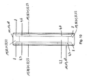
Fig. 8 und eines Rohres, - Fig. 10
- einen Querschnitt der Heizeinheit gemäß
Fig. 8 und des Rohres, - Fig. 11
- eine perspektivische Ansicht eines U-förmigen Abstandshalters in einem zweiten Ausführungsbeispiel für die Heizeinheit gemäß
Fig. 8 , - Fig. 12
- eine vergrößerte Teilansicht des Abstandshalters gemäß
Fig. 11 , - Fig. 13
- eine vergrößerte Teilansicht des Abstandshalters in einem dritten Ausführungsbeispiel,
- Fig. 14
- eine Explosionsdarstellung des Rohres, des Abstandshalters gemäß
Fig. 13 und eines Anschlages und - Fig. 15
- eine perspektivische Ansicht des Abstandshalters in einem vierten Ausführungsbeispiel.
- Fig. 1
- a cross section of an automotive air conditioning system,
- Fig. 2
- a perspective view of a heat exchanger,
- Fig. 3
- a perspective view of a Wärmeleitmodules the heat exchanger according to
Fig. 2 . - Fig. 4
- a perspective view of a heating unit of the heat exchanger according to
Fig. 2 in a first embodiment, - Fig. 5
- an exploded view of the heating unit according to
Fig. 4 . - Fig. 6
- a cross section of the heating unit according to
Fig. 4 in a tube of Wärmeleitmodules according toFig. 3 . - Fig. 7
- a perspective view of the heat exchanger according to
Fig. 2 in a housing, - Fig. 8
- an exploded view of the heating unit in a second embodiment,
- Fig. 9
- a perspective view of the heating unit according to
Fig. 8 and a pipe, - Fig. 10
- a cross section of the heating unit according to
Fig. 8 and the pipe, - Fig. 11
- a perspective view of a U-shaped spacer in a second embodiment of the heating unit according to
Fig. 8 . - Fig. 12
- an enlarged partial view of the spacer according to
Fig. 11 . - Fig. 13
- an enlarged partial view of the spacer in a third embodiment,
- Fig. 14
- an exploded view of the tube, the spacer according to
Fig. 13 and a stop and - Fig. 15
- a perspective view of the spacer in a fourth embodiment.
Die Kraftfahrzeugklimaanlage 24 ist somit nicht mit einem von Kühlmittel durchströmten Wärmeaustauscher versehen zum Erwärmen der durch die Kraftfahrzeuganlage 24 geleiteten Luft. Die durch die Kraftfahrzeugklimaanlage 24 geleitete Luft wird ausschließlich mittels des Wärmeübertrager 1 elektrisch erwärmt. Die Kraftfahrzeugklimaanlage 24 wird vorzugsweise in einem Kraftfahrzeug mit ausschließlich elektrischem Antrieb oder mit einem Hybridantrieb eingesetzt (nicht dargestellt). Um mittels des Wärmeübertragers 1 die notwendige elektrische Heizleistung zu erreichen, muss der Wärmeübertrager mit Hochspannung, z. B. mit mehr als 50 Volt, beispielsweise mit 60 V oder 600 V, betrieben werden, um keine zu großen Stromstärken und damit zu dicke Stromleitungen (nicht dargestellt) zu erhalten.The automotive
Die Wellrippen 12, die Rohre 18 und die Seitenwandungen 16 werden von dem Deckrahmen 14 und dem Bodenrahmen 15 zusammengehalten. Die Verbindung erfolgt vorzugsweise mittels Löten. Hierzu werden die Komponenten 12, 14, 15, 16, 18 in einen Lötofen eingebracht und dadurch die Komponenten 12, 14, 15, 16, 18 miteinander verlötet. Abweichend hiervon ist es auch möglich, dass andere Verbindungsverfahren oder -mittel eingesetzt werden, beispielsweise die Komponenten 12, 14, 15, 16, 18 des Wärmeleitmodules 13 miteinander verschweißt oder gefügt werden. Beim Verbinden mittels Löten treten große Kontaktbereiche zwischen den Wellrippen 12 und den Rohren 18 auf, so dass in vorteilhafter Weise ein hohes thermisches Leitvermögen zwischen den Rohren 18 und den Wellrippen 12 besteht. Die Breite des Wärmeleitmoduls 13 liegt beispielsweise im Bereich von 40 bis 400 mm und die Höhe des Wärmeleitmodules 13 liegt ebenfalls beispielsweise im Bereich von 40 bis 400 mm.The corrugated fins 12, the
In dem von dem Rohr 18 bzw. den Hohlraumwandungen 17 eingeschlossenen Hohlraum 19 ist eine Heizeinheit 10 (
Die beiden Leiterplatten 6, 7, die PTC-Elemente 3 und der Abstandshalter 8 sind stoffschlüssig mit einem Kleber 9, insbesondere Silikonkleber, miteinander verbunden (
Der leere Raum zwischen den beiden Leiterplatten 6, 7 wird von dem Kleber 9 vollständig ausgefüllt.The empty space between the two circuit boards 6, 7 is completely filled by the adhesive 9.
Nach der Herstellung der Wärmeleitmodule 13, d. h. der Montage und dem Löten im Lötofen, werden die vormontierten Heizeinheiten 10 in die Rohre 18 des Wärmeleitmodules 13 eingeschoben. In
Vor oder nach dem Einbringen der Heizeinheiten 10 in die flüssigkeitsdichten und nach unten geschlossenen Rohre 18 wird eine Vergussmasse 23 als elektrisches Isolierelement 22 in die Rohre 18 eingefüllt. Die Vergussmasse 23 ist ein Öl, das einerseits eine hohe thermische Wärmeleitfähigkeit aufweist und andererseits auch über eine große elektrische Isolation verfügt. Aufgrund der Geometrie des Abstandshalters 18 tritt kein unmittelbarer Kontakt zwischen den beiden Leiterplatten 6, 7 und der Hohlraumwandung 17 auf (
Bevorzugt ist die Innenseite der Hohlraumwandung 17 aufgeraut, um die Wärmeübertragungsoberfläche an der Innenseite der Hohlraumwandungen 17 zu erhöhen, so dass die Wärmeleitfähigkeit erhöht wird. Dies kann beispielsweise mit einer mechanischen Aufrauung erfolgen oder auch mit einer Beschichtung. Die Beschichtung ist beispielsweise eine raue Bornitridoberfläche. Das Bornitrid wird vor dem Einbringen des Wärmeleitmodules 13 in den Lötofen auf die aus Aluminium bestehenden Rohre 18 innseitig aufgebracht und im Lötöfen wird das Bornitrid in das Aluminium der Rohre 18 eingebrannt.Preferably, the inside of the cavity wall 17 is roughened to increase the heat transfer surface on the inside of the cavity walls 17, so that the thermal conductivity is increased. This can be done, for example, with a mechanical roughening or with a coating. The coating is, for example, a rough boron nitride surface. The boron nitride is applied before the introduction of the
Der in
Als Vergussmasse 23 wird für einen Wärmeübertrager 1 zum Erwärmen einer Flüssigkeit bevorzugt eine Vergussmasse 23 eingesetzt, die eine erhärtbare Flüssigkeit ist. Nach dem Einbringen der Heizeinheiten 10 in die Rohre 18 wird die flüssige Vergussmasse 23 eingebracht, so dass gemäß der Darstellung in
Eine in
In den
In
In den
Nach dem Aushärten des flüssigen Kunststoffes kann der Anschlag 40 wieder von dem Rohr 18 entfernt werden. Die beiden Abstandshalterstäbe 39 können auch mittels eines Abstandshalterverbindungssteges 41 miteinander verbunden sein (
Insgesamt betrachtet sind mit dem erfindungsgemäßen Wärmeübertrager 1 und der erfindungsgemäßen Kraffifahrzeugklimaanlage 24 wesentliche Vorteile verbunden. Das PTC-Element 3 und die beiden Leiterplatten 6, 7 sind im Wesentlichen vollständig elektrisch gegenüber der Umgebung isoliert, so dass von der Hochspannung keine Gefahr für die Umgebung ausgehen kann.Overall, significant advantages are associated with the
- 11
- WärmeübertragerHeat exchanger
- 22
- Elektrisches WiderstandsheizelementElectric resistance heating element
- 33
- PTC-ElementPTC element
- 44
- Leiterladder
- 55
- Elektrische KontaktplatteElectric contact plate
- 66
- Erste LeiterplatteFirst circuit board
- 77
- Zweite LeiterplatteSecond circuit board
- 88th
- Abstandshalterspacer
- 99
- KleberGlue
- 1010
- Heizeinheitheating unit
- 1111
- Wärmeleitelementthermally conductive element
- 1212
- Wellrippencorrugated fins
- 1313
- Wärmeleitmodulthermal conduction module
- 1414
- Deckrahmencover frame
- 1515
- Bodenrahmenbottom frame
- 1616
- Seitenwandungsidewall
- 1717
- Hohlraumwandungcavity wall
- 1818
- Rohrpipe
- 1919
- Hohlraumcavity
- 2020
- Teilhohlraumpartial cavity
- 2121
- Spaltgap
- 2222
- Elektrisches IsolierelementElectrical insulating element
- 2323
- Vergussmassepotting compound
- 2424
- KraftfahrzeugklimaanlageAutomotive air conditioning system
- 2525
- Gebläsefan
- 2626
- KlimaanlagengehäuseAir conditioning case
- 2727
- Bodenwandungbottom wall
- 2828
- Wandungwall
- 2929
- Austrittsabschnittexit section
- 3030
- Filterfilter
- 3131
- KältemittelverdampferRefrigerant evaporator
- 3232
- Gehäusecasing
- 3333
- EinrittsöffnungEinrittsöffnung
- 3434
- Austrittsöffnungoutlet opening
- 3535
- Kanalchannel
- 3636
- Oberflächesurface
- 3737
- Stegweb
- 3838
- SollbruchstelleBreaking point
- 3939
- AbstandshalterstabSpacer bar
- 4040
- Anschlagattack
- 4141
- AbstandshalterverbindungsstegSpacer connecting web
Claims (15)
dadurch gekennzeichnet, dass
die wenigstens zwei Leiter (4) und/oder das wenigstens eine elektrische Widerstandsheizelement (2) in wenigstens einem von wenigstens einer Hohlraumwandung (17) begrenzten Hohlraum (19) angeordnet sind und das wenigstens eine elektrische Isolierelement (22) eine Vergussmasse (23) ist, welche den Hohlraum (19) dahingehend wenigstens teilweise ausfüllt, dass die wenigstens zwei Leiter (4) und/oder das wenigstens eine elektrische Widerstandsheizelement (2) elektrisch, vorzugsweise von der wenigstens einen Hohlraumwandung (17), wenigstens teilweise isoliert sind.
characterized in that
the at least two conductors (4) and / or the at least one electrical resistance heating element (2) are arranged in at least one cavity (19) delimited by at least one cavity wall (17) and the at least one electrical insulation element (22) is a potting compound (23) which at least partially fills the cavity (19) such that the at least two conductors (4) and / or the at least one electrical resistance heating element (2) is electrically, preferably at least partially insulated, from the at least one cavity wall (17).
dadurch gekennzeichnet, dass
das wenigstens eine Wärmeleitelement (11) wenigstens eine Hohlraumwandung (17) umfasst, welche oder welches wenigstens einen Hohlraum (19) einschließt und in den wenigstens einen Hohlraum (19) die wenigstens zwei Leiter (4) und/oder das wenigstens eine elektrische Widerstandsheizelement (2) angeordnet werden und das wenigstens eine elektrisches Isolierelement (22) eine Vergussmasse (23) ist, welche in den wenigstens einen Hohlraum (19) eingebracht wird, so dass die wenigstens zwei Leiter (4) und/oder das wenigstens eine elektrische Widerstandsheizelement (2) elektrisch, vorzugsweise von der wenigstens einen Hohlraumwandung (17), isoliert sind.
characterized in that
the at least one heat-conducting element (11) comprises at least one cavity wall (17), which encloses at least one cavity (19) and in the at least one cavity (19) the at least two conductors (4) and / or the at least one electrical resistance heating element (17). 2) and the at least one electrical insulating element (22) is a potting compound (23) which is introduced into the at least one cavity (19) so that the at least two conductors (4) and / or the at least one electrical resistance heating element ( 2) are electrically, preferably from the at least one cavity wall (17) isolated.
Priority Applications (1)
| Application Number | Priority Date | Filing Date | Title |
|---|---|---|---|
| EP10150054A EP2211590B1 (en) | 2009-01-23 | 2010-01-04 | Heat exchanger |
Applications Claiming Priority (2)
| Application Number | Priority Date | Filing Date | Title |
|---|---|---|---|
| EP09290047A EP2211589A1 (en) | 2009-01-23 | 2009-01-23 | Heat exchanger |
| EP10150054A EP2211590B1 (en) | 2009-01-23 | 2010-01-04 | Heat exchanger |
Publications (2)
| Publication Number | Publication Date |
|---|---|
| EP2211590A1 true EP2211590A1 (en) | 2010-07-28 |
| EP2211590B1 EP2211590B1 (en) | 2011-10-05 |
Family
ID=40651411
Family Applications (2)
| Application Number | Title | Priority Date | Filing Date |
|---|---|---|---|
| EP09290047A Withdrawn EP2211589A1 (en) | 2009-01-23 | 2009-01-23 | Heat exchanger |
| EP10150054A Active EP2211590B1 (en) | 2009-01-23 | 2010-01-04 | Heat exchanger |
Family Applications Before (1)
| Application Number | Title | Priority Date | Filing Date |
|---|---|---|---|
| EP09290047A Withdrawn EP2211589A1 (en) | 2009-01-23 | 2009-01-23 | Heat exchanger |
Country Status (3)
| Country | Link |
|---|---|
| EP (2) | EP2211589A1 (en) |
| CN (1) | CN101949584B (en) |
| AT (1) | ATE527855T1 (en) |
Cited By (4)
| Publication number | Priority date | Publication date | Assignee | Title |
|---|---|---|---|---|
| EP3101365A1 (en) * | 2015-06-02 | 2016-12-07 | Eberspächer catem GmbH & Co. KG | Method for producing an electrical heating device |
| DE102016203939A1 (en) * | 2016-03-10 | 2017-09-14 | Mahle International Gmbh | Device for heating fluids |
| WO2018172084A1 (en) * | 2017-03-21 | 2018-09-27 | BSH Hausgeräte GmbH | Heat exchanger, and refrigeration appliance equipped therewith |
| US10524310B2 (en) | 2015-06-02 | 2019-12-31 | Eberspächer Catem Gmbh & Co. Kg | PTC heating element and electric heating device for an automotive vehicle comprising such a PTC heating element |
Families Citing this family (14)
| Publication number | Priority date | Publication date | Assignee | Title |
|---|---|---|---|---|
| EP2395296B1 (en) * | 2010-06-11 | 2016-04-27 | MAHLE Behr GmbH & Co. KG | Heat exchanger |
| EP2602567B1 (en) * | 2011-12-05 | 2016-05-11 | Mahle Behr France Rouffach S.A.S | Electric heating device |
| EP2608633B1 (en) | 2011-12-22 | 2020-08-26 | Eberspächer catem GmbH & Co. KG | Element which produces heat |
| FR2991636B1 (en) * | 2012-06-08 | 2014-06-13 | Valeo Systemes Thermiques | INSTALLATION OF THERMAL CONDITIONING OF A HABITACLE OF A VEHICLE, IN PARTICULAR AN ELECTRIC VEHICLE. |
| WO2016095804A1 (en) * | 2014-12-16 | 2016-06-23 | 宋正贤 | Electrical heat-generating device |
| EP3073801A1 (en) * | 2015-03-26 | 2016-09-28 | Betacera Inc. | Integrally formed heater |
| EP3101998B1 (en) * | 2015-06-02 | 2020-12-16 | Eberspächer catem GmbH & Co. KG | Ptc heating element and electric heating device containing such a ptc heating element and method for manufacturing an electric heating device |
| CN105934000A (en) * | 2016-06-24 | 2016-09-07 | 无锡市豫达换热器有限公司 | Novel PTC heating heat exchanger |
| DE102017001461A1 (en) * | 2017-02-08 | 2018-08-09 | Gebr. Krallmann Gmbh | Heating and / or cooling device for a solid or a fluid stream |
| DE102017223779A1 (en) * | 2017-12-22 | 2019-06-27 | Eberspächer Catem Gmbh & Co. Kg | Electric heating device and a method for producing the same |
| FR3077460B1 (en) * | 2018-01-31 | 2020-05-22 | Valeo Systemes Thermiques | HEATING UNIT, HEATING RADIATOR AND AIR CONDITIONING UNIT, ESPECIALLY A MOTOR VEHICLE |
| DE102018218667A1 (en) * | 2018-10-31 | 2020-04-30 | Mahle International Gmbh | PTC heating module and a method for manufacturing the PTC heating module |
| EP3789692A1 (en) * | 2019-09-04 | 2021-03-10 | Mahle International GmbH | Heating element, heating assembly and motor vehicle |
| DE102021103480A1 (en) * | 2021-02-15 | 2022-08-18 | Tdk Electronics Ag | PTC heating element, electric heating device and use of a PTC heating element |
Citations (6)
| Publication number | Priority date | Publication date | Assignee | Title |
|---|---|---|---|---|
| US4327282A (en) | 1978-10-21 | 1982-04-27 | Firma Fritz Eichenauer | Electrical resistance heating element |
| EP0350528A1 (en) * | 1988-07-15 | 1990-01-17 | David & Baader DBK Spezialfabrik elektrischer Apparate und Heizwiderstände GmbH | Radiator |
| EP0575649A1 (en) * | 1992-06-23 | 1993-12-29 | David & Baader DBK Spezialfabrik elektrischer Apparate und Heizwiderstände GmbH | Radiator |
| GB2402876A (en) * | 2003-09-08 | 2004-12-22 | Conair | Hair styling appliance |
| EP1768458A1 (en) | 2005-09-23 | 2007-03-28 | Catem GmbH & Co.KG | Heat generating element of a heating device |
| EP1799015A1 (en) * | 2005-12-14 | 2007-06-20 | DBK David + Baader GmbH | Heating device for a personal care apparatus and method of manufacturing the same |
Family Cites Families (3)
| Publication number | Priority date | Publication date | Assignee | Title |
|---|---|---|---|---|
| US6925826B2 (en) * | 2003-05-05 | 2005-08-09 | Carrier Corporation | Modular bus air conditioning system |
| JP2005001447A (en) * | 2003-06-10 | 2005-01-06 | Denso Corp | Electric heater, heat exchanger for heating and vehicular air conditioner |
| ATE336152T1 (en) * | 2003-12-12 | 2006-09-15 | Behr France Rouffach Sas | ELECTRIC HEATING DEVICE FOR A MOTOR VEHICLE |
-
2009
- 2009-01-23 EP EP09290047A patent/EP2211589A1/en not_active Withdrawn
-
2010
- 2010-01-04 EP EP10150054A patent/EP2211590B1/en active Active
- 2010-01-04 AT AT10150054T patent/ATE527855T1/en active
- 2010-01-22 CN CN201010119153.XA patent/CN101949584B/en active Active
Patent Citations (6)
| Publication number | Priority date | Publication date | Assignee | Title |
|---|---|---|---|---|
| US4327282A (en) | 1978-10-21 | 1982-04-27 | Firma Fritz Eichenauer | Electrical resistance heating element |
| EP0350528A1 (en) * | 1988-07-15 | 1990-01-17 | David & Baader DBK Spezialfabrik elektrischer Apparate und Heizwiderstände GmbH | Radiator |
| EP0575649A1 (en) * | 1992-06-23 | 1993-12-29 | David & Baader DBK Spezialfabrik elektrischer Apparate und Heizwiderstände GmbH | Radiator |
| GB2402876A (en) * | 2003-09-08 | 2004-12-22 | Conair | Hair styling appliance |
| EP1768458A1 (en) | 2005-09-23 | 2007-03-28 | Catem GmbH & Co.KG | Heat generating element of a heating device |
| EP1799015A1 (en) * | 2005-12-14 | 2007-06-20 | DBK David + Baader GmbH | Heating device for a personal care apparatus and method of manufacturing the same |
Cited By (4)
| Publication number | Priority date | Publication date | Assignee | Title |
|---|---|---|---|---|
| EP3101365A1 (en) * | 2015-06-02 | 2016-12-07 | Eberspächer catem GmbH & Co. KG | Method for producing an electrical heating device |
| US10524310B2 (en) | 2015-06-02 | 2019-12-31 | Eberspächer Catem Gmbh & Co. Kg | PTC heating element and electric heating device for an automotive vehicle comprising such a PTC heating element |
| DE102016203939A1 (en) * | 2016-03-10 | 2017-09-14 | Mahle International Gmbh | Device for heating fluids |
| WO2018172084A1 (en) * | 2017-03-21 | 2018-09-27 | BSH Hausgeräte GmbH | Heat exchanger, and refrigeration appliance equipped therewith |
Also Published As
| Publication number | Publication date |
|---|---|
| CN101949584B (en) | 2014-12-10 |
| ATE527855T1 (en) | 2011-10-15 |
| EP2211589A1 (en) | 2010-07-28 |
| EP2211590B1 (en) | 2011-10-05 |
| CN101949584A (en) | 2011-01-19 |
Similar Documents
| Publication | Publication Date | Title |
|---|---|---|
| EP2211590B1 (en) | Heat exchanger | |
| EP2724086B1 (en) | Heat exchanger | |
| EP2428746B1 (en) | Heat exchanger | |
| EP2428747B1 (en) | Heat exchanger | |
| EP2190256B1 (en) | Heat exchanger | |
| EP2395295B1 (en) | Heat exchanger | |
| EP2397788A1 (en) | Heat exchanger and method for manufacturing a heat exchanger | |
| EP2792211B1 (en) | Electrically operable heating device | |
| EP3101364B1 (en) | Electric heating device | |
| EP2608632B1 (en) | Electrical heating device and frame for same | |
| DE202011110647U1 (en) | Electric vehicle heater | |
| EP1768458A1 (en) | Heat generating element of a heating device | |
| EP2346304B1 (en) | Heat exchanger | |
| WO2004080738A1 (en) | Electrical heating device, especially for motor vehicles | |
| EP2395296B1 (en) | Heat exchanger | |
| EP2276321B1 (en) | Heat exchanger | |
| WO2009083107A1 (en) | Heating device | |
| WO2021155997A1 (en) | Electric heating device, and method for producing a heating device | |
| EP2296432B1 (en) | Heat exchanger | |
| EP2474793B1 (en) | Heat exchanger | |
| EP2190257A1 (en) | Heat exchanger | |
| EP2293648A1 (en) | Heat exchanger | |
| EP2469213B1 (en) | Thermo-electric heat exchange | |
| EP3353475B1 (en) | Heat exchanger and vehicle comprising such a heat exchanger | |
| DE102018214484A1 (en) | Electric heater and manufacturing method |
Legal Events
| Date | Code | Title | Description |
|---|---|---|---|
| PUAI | Public reference made under article 153(3) epc to a published international application that has entered the european phase |
Free format text: ORIGINAL CODE: 0009012 |
|
| AK | Designated contracting states |
Kind code of ref document: A1 Designated state(s): AT BE BG CH CY CZ DE DK EE ES FI FR GB GR HR HU IE IS IT LI LT LU LV MC MK MT NL NO PL PT RO SE SI SK SM TR |
|
| AX | Request for extension of the european patent |
Extension state: AL BA RS |
|
| 17P | Request for examination filed |
Effective date: 20110128 |
|
| GRAP | Despatch of communication of intention to grant a patent |
Free format text: ORIGINAL CODE: EPIDOSNIGR1 |
|
| RIC1 | Information provided on ipc code assigned before grant |
Ipc: F24H 3/04 20060101ALI20110407BHEP Ipc: H05B 3/50 20060101AFI20110407BHEP |
|
| GRAS | Grant fee paid |
Free format text: ORIGINAL CODE: EPIDOSNIGR3 |
|
| GRAA | (expected) grant |
Free format text: ORIGINAL CODE: 0009210 |
|
| AK | Designated contracting states |
Kind code of ref document: B1 Designated state(s): AT BE BG CH CY CZ DE DK EE ES FI FR GB GR HR HU IE IS IT LI LT LU LV MC MK MT NL NO PL PT RO SE SI SK SM TR |
|
| REG | Reference to a national code |
Ref country code: GB Ref legal event code: FG4D Free format text: NOT ENGLISH |
|
| REG | Reference to a national code |
Ref country code: CH Ref legal event code: EP |
|
| REG | Reference to a national code |
Ref country code: IE Ref legal event code: FG4D |
|
| REG | Reference to a national code |
Ref country code: DE Ref legal event code: R096 Ref document number: 502010000138 Country of ref document: DE Effective date: 20111201 |
|
| REG | Reference to a national code |
Ref country code: NL Ref legal event code: VDEP Effective date: 20111005 |
|
| PG25 | Lapsed in a contracting state [announced via postgrant information from national office to epo] |
Ref country code: SI Free format text: LAPSE BECAUSE OF FAILURE TO SUBMIT A TRANSLATION OF THE DESCRIPTION OR TO PAY THE FEE WITHIN THE PRESCRIBED TIME-LIMIT Effective date: 20111005 |
|
| LTIE | Lt: invalidation of european patent or patent extension |
Effective date: 20111005 |
|
| PG25 | Lapsed in a contracting state [announced via postgrant information from national office to epo] |
Ref country code: LT Free format text: LAPSE BECAUSE OF FAILURE TO SUBMIT A TRANSLATION OF THE DESCRIPTION OR TO PAY THE FEE WITHIN THE PRESCRIBED TIME-LIMIT Effective date: 20111005 Ref country code: IS Free format text: LAPSE BECAUSE OF FAILURE TO SUBMIT A TRANSLATION OF THE DESCRIPTION OR TO PAY THE FEE WITHIN THE PRESCRIBED TIME-LIMIT Effective date: 20120205 Ref country code: NO Free format text: LAPSE BECAUSE OF FAILURE TO SUBMIT A TRANSLATION OF THE DESCRIPTION OR TO PAY THE FEE WITHIN THE PRESCRIBED TIME-LIMIT Effective date: 20120105 |
|
| REG | Reference to a national code |
Ref country code: IE Ref legal event code: FD4D |
|
| PG25 | Lapsed in a contracting state [announced via postgrant information from national office to epo] |
Ref country code: NL Free format text: LAPSE BECAUSE OF FAILURE TO SUBMIT A TRANSLATION OF THE DESCRIPTION OR TO PAY THE FEE WITHIN THE PRESCRIBED TIME-LIMIT Effective date: 20111005 Ref country code: PT Free format text: LAPSE BECAUSE OF FAILURE TO SUBMIT A TRANSLATION OF THE DESCRIPTION OR TO PAY THE FEE WITHIN THE PRESCRIBED TIME-LIMIT Effective date: 20120206 Ref country code: HR Free format text: LAPSE BECAUSE OF FAILURE TO SUBMIT A TRANSLATION OF THE DESCRIPTION OR TO PAY THE FEE WITHIN THE PRESCRIBED TIME-LIMIT Effective date: 20111005 Ref country code: GR Free format text: LAPSE BECAUSE OF FAILURE TO SUBMIT A TRANSLATION OF THE DESCRIPTION OR TO PAY THE FEE WITHIN THE PRESCRIBED TIME-LIMIT Effective date: 20120106 Ref country code: LV Free format text: LAPSE BECAUSE OF FAILURE TO SUBMIT A TRANSLATION OF THE DESCRIPTION OR TO PAY THE FEE WITHIN THE PRESCRIBED TIME-LIMIT Effective date: 20111005 Ref country code: SE Free format text: LAPSE BECAUSE OF FAILURE TO SUBMIT A TRANSLATION OF THE DESCRIPTION OR TO PAY THE FEE WITHIN THE PRESCRIBED TIME-LIMIT Effective date: 20111005 |
|
| PG25 | Lapsed in a contracting state [announced via postgrant information from national office to epo] |
Ref country code: CY Free format text: LAPSE BECAUSE OF FAILURE TO SUBMIT A TRANSLATION OF THE DESCRIPTION OR TO PAY THE FEE WITHIN THE PRESCRIBED TIME-LIMIT Effective date: 20111005 |
|
| BERE | Be: lapsed |
Owner name: BEHR G.M.B.H. & CO. KG Effective date: 20120131 Owner name: BEHR FRANCE ROUFFACH SAS Effective date: 20120131 |
|
| PG25 | Lapsed in a contracting state [announced via postgrant information from national office to epo] |
Ref country code: IE Free format text: LAPSE BECAUSE OF FAILURE TO SUBMIT A TRANSLATION OF THE DESCRIPTION OR TO PAY THE FEE WITHIN THE PRESCRIBED TIME-LIMIT Effective date: 20111005 Ref country code: DK Free format text: LAPSE BECAUSE OF FAILURE TO SUBMIT A TRANSLATION OF THE DESCRIPTION OR TO PAY THE FEE WITHIN THE PRESCRIBED TIME-LIMIT Effective date: 20111005 Ref country code: EE Free format text: LAPSE BECAUSE OF FAILURE TO SUBMIT A TRANSLATION OF THE DESCRIPTION OR TO PAY THE FEE WITHIN THE PRESCRIBED TIME-LIMIT Effective date: 20111005 Ref country code: SK Free format text: LAPSE BECAUSE OF FAILURE TO SUBMIT A TRANSLATION OF THE DESCRIPTION OR TO PAY THE FEE WITHIN THE PRESCRIBED TIME-LIMIT Effective date: 20111005 Ref country code: BG Free format text: LAPSE BECAUSE OF FAILURE TO SUBMIT A TRANSLATION OF THE DESCRIPTION OR TO PAY THE FEE WITHIN THE PRESCRIBED TIME-LIMIT Effective date: 20120105 |
|
| PLBE | No opposition filed within time limit |
Free format text: ORIGINAL CODE: 0009261 |
|
| STAA | Information on the status of an ep patent application or granted ep patent |
Free format text: STATUS: NO OPPOSITION FILED WITHIN TIME LIMIT |
|
| PG25 | Lapsed in a contracting state [announced via postgrant information from national office to epo] |
Ref country code: IT Free format text: LAPSE BECAUSE OF FAILURE TO SUBMIT A TRANSLATION OF THE DESCRIPTION OR TO PAY THE FEE WITHIN THE PRESCRIBED TIME-LIMIT Effective date: 20111005 Ref country code: MC Free format text: LAPSE BECAUSE OF NON-PAYMENT OF DUE FEES Effective date: 20120131 Ref country code: RO Free format text: LAPSE BECAUSE OF FAILURE TO SUBMIT A TRANSLATION OF THE DESCRIPTION OR TO PAY THE FEE WITHIN THE PRESCRIBED TIME-LIMIT Effective date: 20111005 Ref country code: PL Free format text: LAPSE BECAUSE OF FAILURE TO SUBMIT A TRANSLATION OF THE DESCRIPTION OR TO PAY THE FEE WITHIN THE PRESCRIBED TIME-LIMIT Effective date: 20111005 |
|
| 26N | No opposition filed |
Effective date: 20120706 |
|
| REG | Reference to a national code |
Ref country code: DE Ref legal event code: R097 Ref document number: 502010000138 Country of ref document: DE Effective date: 20120706 |
|
| PG25 | Lapsed in a contracting state [announced via postgrant information from national office to epo] |
Ref country code: BE Free format text: LAPSE BECAUSE OF NON-PAYMENT OF DUE FEES Effective date: 20120131 |
|
| PG25 | Lapsed in a contracting state [announced via postgrant information from national office to epo] |
Ref country code: MK Free format text: LAPSE BECAUSE OF FAILURE TO SUBMIT A TRANSLATION OF THE DESCRIPTION OR TO PAY THE FEE WITHIN THE PRESCRIBED TIME-LIMIT Effective date: 20111005 |
|
| PG25 | Lapsed in a contracting state [announced via postgrant information from national office to epo] |
Ref country code: ES Free format text: LAPSE BECAUSE OF FAILURE TO SUBMIT A TRANSLATION OF THE DESCRIPTION OR TO PAY THE FEE WITHIN THE PRESCRIBED TIME-LIMIT Effective date: 20120116 |
|
| PG25 | Lapsed in a contracting state [announced via postgrant information from national office to epo] |
Ref country code: FI Free format text: LAPSE BECAUSE OF FAILURE TO SUBMIT A TRANSLATION OF THE DESCRIPTION OR TO PAY THE FEE WITHIN THE PRESCRIBED TIME-LIMIT Effective date: 20111005 |
|
| PG25 | Lapsed in a contracting state [announced via postgrant information from national office to epo] |
Ref country code: MT Free format text: LAPSE BECAUSE OF FAILURE TO SUBMIT A TRANSLATION OF THE DESCRIPTION OR TO PAY THE FEE WITHIN THE PRESCRIBED TIME-LIMIT Effective date: 20111005 |
|
| PG25 | Lapsed in a contracting state [announced via postgrant information from national office to epo] |
Ref country code: TR Free format text: LAPSE BECAUSE OF FAILURE TO SUBMIT A TRANSLATION OF THE DESCRIPTION OR TO PAY THE FEE WITHIN THE PRESCRIBED TIME-LIMIT Effective date: 20111005 |
|
| PG25 | Lapsed in a contracting state [announced via postgrant information from national office to epo] |
Ref country code: LU Free format text: LAPSE BECAUSE OF NON-PAYMENT OF DUE FEES Effective date: 20120104 Ref country code: SM Free format text: LAPSE BECAUSE OF FAILURE TO SUBMIT A TRANSLATION OF THE DESCRIPTION OR TO PAY THE FEE WITHIN THE PRESCRIBED TIME-LIMIT Effective date: 20111005 |
|
| PG25 | Lapsed in a contracting state [announced via postgrant information from national office to epo] |
Ref country code: HU Free format text: LAPSE BECAUSE OF FAILURE TO SUBMIT A TRANSLATION OF THE DESCRIPTION OR TO PAY THE FEE WITHIN THE PRESCRIBED TIME-LIMIT Effective date: 20100104 |
|
| REG | Reference to a national code |
Ref country code: CH Ref legal event code: PL |
|
| GBPC | Gb: european patent ceased through non-payment of renewal fee |
Effective date: 20140104 |
|
| PG25 | Lapsed in a contracting state [announced via postgrant information from national office to epo] |
Ref country code: CH Free format text: LAPSE BECAUSE OF NON-PAYMENT OF DUE FEES Effective date: 20140131 Ref country code: LI Free format text: LAPSE BECAUSE OF NON-PAYMENT OF DUE FEES Effective date: 20140131 |
|
| PG25 | Lapsed in a contracting state [announced via postgrant information from national office to epo] |
Ref country code: GB Free format text: LAPSE BECAUSE OF NON-PAYMENT OF DUE FEES Effective date: 20140104 |
|
| REG | Reference to a national code |
Ref country code: DE Ref legal event code: R082 Ref document number: 502010000138 Country of ref document: DE Representative=s name: GRAUEL, ANDREAS, DIPL.-PHYS. DR. RER. NAT., DE Ref country code: DE Ref legal event code: R081 Ref document number: 502010000138 Country of ref document: DE Owner name: MAHLE INTERNATIONAL GMBH, DE Free format text: FORMER OWNERS: BEHR FRANCE ROUFFACH SAS, ROUFFACH, FR; BEHR GMBH & CO. KG, 70469 STUTTGART, DE |
|
| REG | Reference to a national code |
Ref country code: FR Ref legal event code: PLFP Year of fee payment: 7 |
|
| REG | Reference to a national code |
Ref country code: AT Ref legal event code: MM01 Ref document number: 527855 Country of ref document: AT Kind code of ref document: T Effective date: 20150104 |
|
| PG25 | Lapsed in a contracting state [announced via postgrant information from national office to epo] |
Ref country code: AT Free format text: LAPSE BECAUSE OF NON-PAYMENT OF DUE FEES Effective date: 20150104 |
|
| REG | Reference to a national code |
Ref country code: FR Ref legal event code: PLFP Year of fee payment: 8 |
|
| REG | Reference to a national code |
Ref country code: FR Ref legal event code: PLFP Year of fee payment: 9 |
|
| PGFP | Annual fee paid to national office [announced via postgrant information from national office to epo] |
Ref country code: CZ Payment date: 20181219 Year of fee payment: 10 |
|
| PGFP | Annual fee paid to national office [announced via postgrant information from national office to epo] |
Ref country code: GB Payment date: 20190313 Year of fee payment: 10 |
|
| PG25 | Lapsed in a contracting state [announced via postgrant information from national office to epo] |
Ref country code: CZ Free format text: LAPSE BECAUSE OF NON-PAYMENT OF DUE FEES Effective date: 20200104 |
|
| PG25 | Lapsed in a contracting state [announced via postgrant information from national office to epo] |
Ref country code: FR Free format text: LAPSE BECAUSE OF NON-PAYMENT OF DUE FEES Effective date: 20200131 |
|
| PGFP | Annual fee paid to national office [announced via postgrant information from national office to epo] |
Ref country code: DE Payment date: 20230316 Year of fee payment: 14 |