EP2608633B1 - Element which produces heat - Google Patents
Element which produces heat Download PDFInfo
- Publication number
- EP2608633B1 EP2608633B1 EP11010088.0A EP11010088A EP2608633B1 EP 2608633 B1 EP2608633 B1 EP 2608633B1 EP 11010088 A EP11010088 A EP 11010088A EP 2608633 B1 EP2608633 B1 EP 2608633B1
- Authority
- EP
- European Patent Office
- Prior art keywords
- sheet metal
- elements
- heating device
- contact
- housing
- Prior art date
- Legal status (The legal status is an assumption and is not a legal conclusion. Google has not performed a legal analysis and makes no representation as to the accuracy of the status listed.)
- Active
Links
- 229910052751 metal Inorganic materials 0.000 claims description 98
- 239000002184 metal Substances 0.000 claims description 98
- 238000010438 heat treatment Methods 0.000 claims description 68
- 239000004033 plastic Substances 0.000 claims description 51
- 238000007789 sealing Methods 0.000 claims description 43
- 238000001816 cooling Methods 0.000 claims description 17
- 230000000284 resting effect Effects 0.000 claims description 4
- 238000005485 electric heating Methods 0.000 claims 2
- 238000003780 insertion Methods 0.000 description 14
- 230000037431 insertion Effects 0.000 description 14
- 238000011161 development Methods 0.000 description 13
- 210000002105 tongue Anatomy 0.000 description 12
- 238000012360 testing method Methods 0.000 description 8
- 239000000853 adhesive Substances 0.000 description 7
- 230000001070 adhesive effect Effects 0.000 description 7
- 238000005452 bending Methods 0.000 description 7
- 238000004080 punching Methods 0.000 description 6
- 238000013461 design Methods 0.000 description 5
- 239000004065 semiconductor Substances 0.000 description 5
- 238000012546 transfer Methods 0.000 description 5
- 230000006835 compression Effects 0.000 description 4
- 238000007906 compression Methods 0.000 description 4
- 238000010292 electrical insulation Methods 0.000 description 4
- 238000009434 installation Methods 0.000 description 4
- 238000004519 manufacturing process Methods 0.000 description 4
- 239000000463 material Substances 0.000 description 4
- 239000000919 ceramic Substances 0.000 description 3
- 239000004020 conductor Substances 0.000 description 3
- 238000009413 insulation Methods 0.000 description 3
- 229910052782 aluminium Inorganic materials 0.000 description 2
- XAGFODPZIPBFFR-UHFFFAOYSA-N aluminium Chemical compound [Al] XAGFODPZIPBFFR-UHFFFAOYSA-N 0.000 description 2
- 230000008901 benefit Effects 0.000 description 2
- 238000005553 drilling Methods 0.000 description 2
- 238000001746 injection moulding Methods 0.000 description 2
- 230000003993 interaction Effects 0.000 description 2
- 238000012423 maintenance Methods 0.000 description 2
- 239000007769 metal material Substances 0.000 description 2
- 239000002985 plastic film Substances 0.000 description 2
- 229920006255 plastic film Polymers 0.000 description 2
- RYGMFSIKBFXOCR-UHFFFAOYSA-N Copper Chemical compound [Cu] RYGMFSIKBFXOCR-UHFFFAOYSA-N 0.000 description 1
- 230000003213 activating effect Effects 0.000 description 1
- 239000011324 bead Substances 0.000 description 1
- 230000005540 biological transmission Effects 0.000 description 1
- 230000015572 biosynthetic process Effects 0.000 description 1
- 230000008859 change Effects 0.000 description 1
- 239000002800 charge carrier Substances 0.000 description 1
- 210000000078 claw Anatomy 0.000 description 1
- 230000000295 complement effect Effects 0.000 description 1
- 238000010276 construction Methods 0.000 description 1
- 238000011109 contamination Methods 0.000 description 1
- 230000001276 controlling effect Effects 0.000 description 1
- 229910052802 copper Inorganic materials 0.000 description 1
- 239000010949 copper Substances 0.000 description 1
- 238000002788 crimping Methods 0.000 description 1
- 230000007547 defect Effects 0.000 description 1
- 230000000694 effects Effects 0.000 description 1
- 229920001971 elastomer Polymers 0.000 description 1
- 239000000806 elastomer Substances 0.000 description 1
- 239000013536 elastomeric material Substances 0.000 description 1
- 239000012777 electrically insulating material Substances 0.000 description 1
- 230000005670 electromagnetic radiation Effects 0.000 description 1
- 230000002706 hydrostatic effect Effects 0.000 description 1
- 230000001771 impaired effect Effects 0.000 description 1
- 238000005304 joining Methods 0.000 description 1
- 238000012544 monitoring process Methods 0.000 description 1
- 239000012811 non-conductive material Substances 0.000 description 1
- 229920001343 polytetrafluoroethylene Polymers 0.000 description 1
- 239000004810 polytetrafluoroethylene Substances 0.000 description 1
- 238000007639 printing Methods 0.000 description 1
- 230000001105 regulatory effect Effects 0.000 description 1
- 238000005507 spraying Methods 0.000 description 1
- 239000003351 stiffener Substances 0.000 description 1
- 229920002725 thermoplastic elastomer Polymers 0.000 description 1
- 238000012549 training Methods 0.000 description 1
- 230000007704 transition Effects 0.000 description 1
Images


Classifications
-
- H—ELECTRICITY
- H05—ELECTRIC TECHNIQUES NOT OTHERWISE PROVIDED FOR
- H05B—ELECTRIC HEATING; ELECTRIC LIGHT SOURCES NOT OTHERWISE PROVIDED FOR; CIRCUIT ARRANGEMENTS FOR ELECTRIC LIGHT SOURCES, IN GENERAL
- H05B3/00—Ohmic-resistance heating
- H05B3/40—Heating elements having the shape of rods or tubes
- H05B3/42—Heating elements having the shape of rods or tubes non-flexible
- H05B3/46—Heating elements having the shape of rods or tubes non-flexible heating conductor mounted on insulating base
-
- H—ELECTRICITY
- H05—ELECTRIC TECHNIQUES NOT OTHERWISE PROVIDED FOR
- H05B—ELECTRIC HEATING; ELECTRIC LIGHT SOURCES NOT OTHERWISE PROVIDED FOR; CIRCUIT ARRANGEMENTS FOR ELECTRIC LIGHT SOURCES, IN GENERAL
- H05B3/00—Ohmic-resistance heating
- H05B3/02—Details
-
- H—ELECTRICITY
- H05—ELECTRIC TECHNIQUES NOT OTHERWISE PROVIDED FOR
- H05B—ELECTRIC HEATING; ELECTRIC LIGHT SOURCES NOT OTHERWISE PROVIDED FOR; CIRCUIT ARRANGEMENTS FOR ELECTRIC LIGHT SOURCES, IN GENERAL
- H05B3/00—Ohmic-resistance heating
- H05B3/20—Heating elements having extended surface area substantially in a two-dimensional plane, e.g. plate-heater
- H05B3/22—Heating elements having extended surface area substantially in a two-dimensional plane, e.g. plate-heater non-flexible
- H05B3/28—Heating elements having extended surface area substantially in a two-dimensional plane, e.g. plate-heater non-flexible heating conductor embedded in insulating material
- H05B3/30—Heating elements having extended surface area substantially in a two-dimensional plane, e.g. plate-heater non-flexible heating conductor embedded in insulating material on or between metallic plates
-
- B—PERFORMING OPERATIONS; TRANSPORTING
- B60—VEHICLES IN GENERAL
- B60H—ARRANGEMENTS OF HEATING, COOLING, VENTILATING OR OTHER AIR-TREATING DEVICES SPECIALLY ADAPTED FOR PASSENGER OR GOODS SPACES OF VEHICLES
- B60H1/00—Heating, cooling or ventilating [HVAC] devices
- B60H1/22—Heating, cooling or ventilating [HVAC] devices the heat being derived otherwise than from the propulsion plant
- B60H1/2215—Heating, cooling or ventilating [HVAC] devices the heat being derived otherwise than from the propulsion plant the heat being derived from electric heaters
- B60H1/2225—Heating, cooling or ventilating [HVAC] devices the heat being derived otherwise than from the propulsion plant the heat being derived from electric heaters arrangements of electric heaters for heating air
-
- H—ELECTRICITY
- H05—ELECTRIC TECHNIQUES NOT OTHERWISE PROVIDED FOR
- H05B—ELECTRIC HEATING; ELECTRIC LIGHT SOURCES NOT OTHERWISE PROVIDED FOR; CIRCUIT ARRANGEMENTS FOR ELECTRIC LIGHT SOURCES, IN GENERAL
- H05B2203/00—Aspects relating to Ohmic resistive heating covered by group H05B3/00
- H05B2203/02—Heaters using heating elements having a positive temperature coefficient
-
- H—ELECTRICITY
- H05—ELECTRIC TECHNIQUES NOT OTHERWISE PROVIDED FOR
- H05B—ELECTRIC HEATING; ELECTRIC LIGHT SOURCES NOT OTHERWISE PROVIDED FOR; CIRCUIT ARRANGEMENTS FOR ELECTRIC LIGHT SOURCES, IN GENERAL
- H05B2203/00—Aspects relating to Ohmic resistive heating covered by group H05B3/00
- H05B2203/022—Heaters specially adapted for heating gaseous material
- H05B2203/023—Heaters of the type used for electrically heating the air blown in a vehicle compartment by the vehicle heating system
-
- H—ELECTRICITY
- H05—ELECTRIC TECHNIQUES NOT OTHERWISE PROVIDED FOR
- H05B—ELECTRIC HEATING; ELECTRIC LIGHT SOURCES NOT OTHERWISE PROVIDED FOR; CIRCUIT ARRANGEMENTS FOR ELECTRIC LIGHT SOURCES, IN GENERAL
- H05B3/00—Ohmic-resistance heating
- H05B3/40—Heating elements having the shape of rods or tubes
- H05B3/42—Heating elements having the shape of rods or tubes non-flexible
- H05B3/48—Heating elements having the shape of rods or tubes non-flexible heating conductor embedded in insulating material
- H05B3/50—Heating elements having the shape of rods or tubes non-flexible heating conductor embedded in insulating material heating conductor arranged in metal tubes, the radiating surface having heat-conducting fins
Definitions
- the present invention relates to a heat-generating element with the preamble features of claim 1 and an electrical heating device with the preamble features of claim 3.
- Such heat-generating elements are generally known as a component of an electrical heating device, in particular for heating the air in a motor vehicle, which is also to be developed further with the present invention.
- the heat-generating element forms a layer of a layer structure which usually comprises corrugated fin elements resting on both sides of the heat-generating element.
- This layer structure usually has a plurality of layers of corrugated fin elements and heat-generating elements that are stacked one on top of the other in one plane.
- a generic heat generating element is from EP 2 190 256 A1 known. Similar heat generating elements are off EP 1 768 457 A1 , EP 2 299 200 A1 and EP 1 768 458 A1 known.
- the EP 0 350 528 discloses a heat generating element as part of an electrical heater for heating air.
- Electrical heating devices comprising a heat-generating element of the generic type sometimes lead to electromagnetic interference, which is particularly undesirable inside a motor vehicle, since this is acoustically noticeable in the vehicle interior, for example when a radio is operated.
- the present invention is based on the problem of specifying a heat-generating element, in particular for an electrical heating device for a motor vehicle, as well as an electrical heating device, which take account of the EMC problem in an improved manner.
- the present invention proposes a heat-generating element having the features of claim 1.
- the heat generating element according to the invention has a position frame in a manner known per se.
- This position frame is usually made of an electrical one Manufactured non-conductive material and forms at least one, usually several receptacles for at least one PTC element.
- PTC elements may be provided.
- Such contact sheets are usually formed from a sheet metal strip by punching, if necessary bending.
- the heat generating element according to the invention also has a sheet metal cover connected to the positioning frame.
- This sheet metal cover is usually provided in an electrically insulating manner from the two contact elements. It can be isolated from the associated contact plate by an air gap, i.e. do not rest on the contact plate, but only on the positioning frame. Usually, and especially with a view to good heat transfer, the sheet metal cover rests indirectly on the contact sheet assigned to it.
- An indirect system usually requires the interposition of an insulating layer between the sheet metal cover and the associated contact sheet.
- This insulating layer can be formed from a plastic film and / or ceramic layer.
- the insulating layer can also be applied by spraying plastic and / or ceramic onto the outer surface of the contact plate and / or the inner surface of the sheet metal cover.
- the sheet metal cover can be connected to the position frame in any desired manner, for example connected to it to form a unit by overmolding, or it can be subsequently attached to a position frame initially prepared by injection molding.
- the sheet metal cover forms a shield for the heat-generating element. Accordingly, an electric heater comprising the heat generating element causes less EMC problems.
- sheet metal covers can be provided so that the heat-generating element is covered by sheet metal on its outside.
- the sheet metal cover usually forms the contact surface for the corrugated rib element or elements.
- the corrugated rib element in the sense of the present invention is not necessarily given by a meandering sheet metal strip.
- the corrugated rib element can also be produced as an extruded profile made of aluminum. The individual webs of such a profile form corrugated ribs of the said corrugated rib element.
- the sheet metal cover has an edge that essentially completely surrounds the positioning frame.
- This edge usually extends the full height of the position frame, i. up to or even above the plane that is defined by the contact plate arranged on the opposite side.
- a sheet metal cover with an edge that essentially surrounds the positioning frame.
- This edge is preferably clipped to the position frame, so that when the heat-generating element is installed, the sheet metal cover can be clipped onto the position frame on one side, if necessary with prior introduction of the insulating layer and the contact sheet.
- the positioning frame can then be arranged with its side that is still open and the PTC element (s) inserted into the receptacle (s).
- the sheet metal cover clipped to the positioning frame accordingly forms a base which is firmly connected to the positioning frame and which simplifies the placement of the respective layers in the heat-generating element.
- Layers are in particular the PTC element (s) and the contact sheet provided on the side opposite the sheet metal cover, possibly an outer insulating layer assigned to it.
- a sheet metal cover is provided on both sides of the heat-generating element.
- the sheet metal cover is located between the corrugated rib elements and the contact plate.
- An insulating layer is regularly provided between the sheet metal cover and the associated contact sheet.
- a generic electrical heating device is from EP 2 190 256 A1 known.
- the sheet metal cover arranged on one side is assigned to the heat-generating element and that on the opposite, i.e. sheet metal cover arranged on the other side of the corrugated fin element.
- the sheet metal cover assigned to the heat-generating element is usually fixedly or detachably connected to the position frame, preferably clipped to it via an edge surrounding the position frame.
- the sheet metal cover assigned to the corrugated fin element can be soldered to the corrugated fins of the corrugated fin element or connected in some other way, for example connected to the corrugated fin element by crimping.
- one sheet metal cover is usually permanently assigned to the positioning frame and the other sheet metal cover is permanently assigned to the corrugated rib element, so that when the layer structure is assembled within the frame, only a reduced number of parts have to be handled in order to provide an electrical one that is better protected against EMC problems Manufacture heating device.
- the heating block have several corrugated rib elements provided one behind the other in the direction of flow of the medium to be heated includes.
- These corrugated rib elements are each arranged one behind the other in identical planes. They are usually provided offset with respect to one another, so that the corrugated ribs of the corrugated rib element against which the flow comes first do not completely cover or shield the corrugated ribs of the subsequent corrugated rib element. Rather, the corrugated fins of the second corrugated fin element in the flow direction are exposed when projected onto the corrugated fin elements arranged one behind the other in the flow direction of the medium to be heated.
- the sheet metal cover provided on the other side has several cover elements.
- Each of the cover elements is assigned to a single corrugated rib element.
- the cover elements arranged one behind the other in the direction of flow of the medium to be heated accordingly form the sheet metal cover on the corrugated rib side.
- the cover elements usually abut one another directly one behind the other in the flow direction so that there is no interference with the shielding on the corrugated rib side between the individual corrugated rib elements.
- the electrical heating device has a connection housing which is provided at a front end of the layer structure.
- a connection housing usually accommodates the electrical connection elements for selected, usually all, contact plates, so that the individual heat-generating elements in the connection housing are electrically connected.
- the connection housing can also have a control device for activating and regulating the individual heat-generating elements. These can be grouped and combined to form different heating levels.
- the connection housing has a shielding housing element. This shielding housing element can be an element which completely or partially forms the housing and which is made from a metallic material.
- the shielding housing element can also be formed merely as a metal or sheet metal shell, which surrounds in a shielding manner the housing shell elements forming the housing and sealing the components provided in the connection housing, in particular the control components.
- the shielding housing element is electrically conductively connected to the sheet metal covers. This results in a uniform shielding that surrounds both the heat-generating elements of the layer structure and the connection housing and accordingly also shields EMC interference that may arise from the connection housing.
- the further training also offers the option of grounding the shielding via the connection housing.
- the shielding housing element is preferably clipped to the sheet metal covers in a conductive manner. Accordingly, clip webs are provided which connect the shielding housing element to the sheet metal covers in an electrically conductive manner.
- the electric Conductive connection is not made directly between the shielding housing element and the sheet metal cover. Rather, since the corrugated rib elements are usually directly, ie electrically conductively connected to the associated sheet metal covers, the electrical contact between the shielding housing element and the sheet metal cover can also be made via the corrugated rib element.
- the shielding housing element can be formed as a cast metallic housing.
- the shielding housing element can also be designed as a plastic housing element, which is received within a sheet metal shell for shielding.
- the shielding housing element forms inlet and outlet openings for a cooling channel that is sealed off from the interior of the connection housing.
- this cooling channel there is usually at least one heat sink which is provided for cooling a circuit breaker accommodated in the connection housing and which gives off its power loss to the medium to be heated in the form of heat.
- the present invention specifies an electrical heating device of the type mentioned above, which has a connection housing which receives electrical contact elements from several heat-generating elements.
- the connection housing regularly serves to connect selected, sometimes all, contact plates to a control device that can be accommodated in the connection housing.
- This control device usually comprises an assembled printed circuit board or circuit board.
- a connection housing can, however, alternatively or additionally comprise circuit boards or conductor elements through which the connected heat-generating elements are contacted or grouped.
- the present invention proposes that the connection housing with a shielding housing element, a plastic housing element received in the shielding housing element and a sealing housing element and / or the plastic housing element be applied Form housing cover element.
- the shielding housing element like the housing cover element, is usually designed as a shielding, that is to say formed from metal or with a metal insert.
- the shielding housing element and the housing cover element shield the interior of the connection housing.
- the shielding housing element and / or the housing cover element are usually electrically connected to the shielding of the layer structure, for example a sheet metal cover of the heat-generating element and / or the corrugated rib elements of the layer structure, so that the electrical heating device has a uniform shield.
- the plastic housing element is correspondingly adapted and designed for receiving or holding the control device and / or for holding connection elements which effect the connection of the electrical heating device.
- the electrical heating device can be connected directly to a power supply via these electrical connection elements.
- corresponding connection elements can only be held in the plastic housing element and made accessible via the housing cover element on the outside of the connection housing.
- the plastic housing element serves to isolate the elements of the control device that conduct and / or switch the power flow or contact surface elements which usually contact or group the connection elements to some or all of the heat-generating elements.
- connection housing simple shielding of the connection housing can be effected, if necessary, including the layer structure.
- the plastic housing element creates a differentiated design for receiving and holding electrically conductive components. Since the plastic housing element is inserted into the shielding housing element, the electrical or electronic components accommodated in the plastic housing element are also shielded.
- the control device has at least one circuit breaker.
- This is a semiconductor power switch which is provided for controlling the thermal output of the element or elements which generate heat and which emits power loss.
- at least one heat sink is assigned to the circuit breaker.
- This heat sink is after added the preferred development in the plastic housing element.
- the plastic housing element can be used to easily form receiving or securing surfaces for holding the heat sink.
- the heat sink is still connected in an electrically conductive manner to the shielding housing element and is accordingly integrated into the shielding.
- it can be determined whether the desired insulation of the grounded parts is still effective, as is the case EP 2 299 200 teaches.
- the heat sink is usually provided electrically insulated from the circuit breaker, although both components are in contact with one another with good thermal conductivity. Accordingly, there is usually electrical insulation between the circuit breaker and the heat sink, which only slightly hinders the passage of heat from the circuit breaker to the heat sink.
- the heat sink is inserted into the housing in a sealing manner. According to this, the sealing of the receiving space of the connection housing brought about by the interaction of the housing cover element and the shielding housing element is not impaired by the heat sink exposed on the outside of the connection housing element.
- This heat sink is usually exposed in the flow of the medium to be heated and is cooled by this flow.
- the heat sink is preferably held in the plastic housing element so as to be movable within limits. The movement of the heat sink usually takes place against a pretension, which is usually brought about by the seal provided for the heat sink.
- the mobility of the cooling body within the connection housing is usually selected so that the cooling body 5/10, preferably 7/10, can move in an insertion movement and thus compensate for thickness tolerances of the circuit breaker without losing the seal.
- a ring-shaped or cylindrical sealing body made of an elastomer is usually used as the sealing element for this. These materials have proven to be particularly suitable for maintaining pretension and tightness even at relatively high temperatures and over a long period of time.
- a sealing element is usually assigned to the connection housing, the compression of which causes the circuit breaker to rest against the heat sink under prestress.
- connection housing usually has support points which are arranged distributed over the circumference of a heat sink insertion opening and on which the sealing element is supported. Laterally next to these support points, the sealing element can migrate in the direction of the layer structure during compression and thus avoid the movement of the cooling body within limits. In other words, the sealing element is not fully supported in the introduction opening, but only at the support points which are distributed in the circumferential direction in the introduction opening.
- connection bolt is held on the plastic housing element, which is connected in an electrically conductive manner to the shielding housing element and accordingly serves to connect the electrical heating device to ground.
- connection housing developed in this way, in cooperation with the connection piece of the heat-generating element, allows a sealed assembly of the heat-generating element in the connection housing.
- the receptacle formed by the heat-generating elements is accordingly sealed off via the connection housing.
- the receptacle is, however, also accessible via the connection housing in order, for example, to introduce contact elements into the heat-generating element.
- connection housing it is also possible, after all the heat-generating elements have been fully installed on the connection housing, to carry out a leak test via this, so that essentially the completely installed electrical heating device is checked for leakage as a whole.
- the socket receptacle is usually formed by a housing base, so that after the leak test, only the housing cover, possibly also electronic components, have to be inserted beforehand in order to complete the electrical heating device with the control device provided in a structural unit.
- connection piece For each contact element of the heat-generating element, a separate connection piece, which is per se sealed in a socket receptacle, is regularly formed. But it is also possible to provide a connection piece that connects all electrical conductor tracks to the interior of the heat-generating element receives and is sealingly received in the nozzle receptacle of the connection housing.
- a sealing element made of an elastomeric material is located between the connecting piece and the connecting piece receptacle.
- This sealing element is applied in a practical manner to the socket before assembly and can be connected by overmolding.
- a connection that is always tight in any case occurs between the sealing element and the associated contact surface, which connection can be a surface of the heat-generating element and a surface of the connection housing.
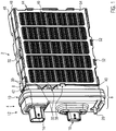
- the Figure 1 shows an exemplary embodiment of an electrical heating device with a power section marked with reference number 2 and a control section marked with reference number 4.
- the power section 2 and the control section 4 form a structural unit of the electrical heating device.
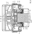
- the control part 4 is formed on the outside by a connection housing 6 which - as in particular the representation according to FIG Figure 4 made clear - a shielding housing 8, which is formed as a deep-drawn or cast or deep-drawn metal shell, for example, a plastic housing element 10, which is inserted into the metal shell 8, and a housing cover 12.
- a shielding housing 8 which is formed as a deep-drawn or cast or deep-drawn metal shell, for example, a plastic housing element 10, which is inserted into the metal shell 8, and a housing cover 12.
- the housing cover 12 can overlap a free flange of the sheet metal trough 8 and be formed from metal, so that the interior of the control part 4 is completely shielded by a metallic connection housing 6.
- the housing cover 12 can also be made of plastic.
- the housing cover 12 carries a female connector housing 14 for the power flow and a further female housing element formed as a control connector housing 16. Both connector housings 14, 16 are connected as plastic elements to the metallic housing cover 12 and each form guide and sliding surfaces for a male connector element (not shown).
- the plastic housing element 10 accommodates a printed circuit board 18 which is partially covered by a pressure element 20, which will be explained in more detail below.
- the circuit board 18 is surmounted by a plus connection plug contact 22 and a minus connection plug contact, which are exposed in the power connector housing and are electrically connected to the conductor track.
- the printed circuit board 18 also carries a control contact element 26 which contains control element contacts and which can be reached via the control connector housing 16 by means of lines. How out Figure 4 As can be seen, the control connector housing 16 is arranged offset to the control contact element 26. This distance is due to the installation situation of the electrical heating device in the motor vehicle.
- the electrical contact between the control contact element 26 and the control connector housing 16, or the contact elements provided there, takes place via electrical lines that are laid on the inside in the housing cover 12.
- the housing cover is also protruded in the assembled state by a connection bolt 28 for the ground connection, which is electrically connected to the shielding housing 8.
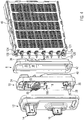
- the plastic housing element 10 forms two cooling channels 30 for heat sinks 32, which are shown in FIG Figure 4 just hinted at, however in the Figures 1 and 5 can be seen more clearly.
- the free end of the heat sinks 32 comprises a plurality of cooling webs which extend essentially parallel to one another and which each define air passage channels 34.
- the heat sinks 32 are made of a material with good thermal conductivity, for example aluminum or copper.
- FIG. 5 has not shown, omitted sheet metal tub - like in particular the Figures 1 and 4th illustrate, corresponding to the cooling channels 30, opposite through openings 36 for air, which are provided as inlet and outlet openings to the cooling channels 30.
- These passage openings 36 are formed in the metal shell 8.
- the metal shell 8 has locking openings 38 through which, after the final assembly of the control part 4 on the power part 2, latching lugs 40 protrude, which engage with the power part 2 in a form-fitting manner and are formed on the outer edge of the plastic housing element 10.
- the metal shell 8 also has fastening bores 42 on opposite end faces, which will be discussed in greater detail below.
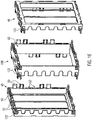
- the power part 2 has a frame 44, which in the embodiment according to Figure 1 is circumferentially closed and circumferentially surrounds a layer structure identified by reference numeral 46, which is also referred to as a heating block.
- the frame 44 is formed from two frame elements 48 which are latched to one another via latching connections, which are designated by reference number 50 (male latching element) and reference number 52 (female latching element), in particular in FIG Figure 16 Marked are.
- the frame 44 forms openings 56 on opposite outer sides 54 for the passage of air to be heated from the air heater shown in the exemplary embodiment.
- these openings 56 are stiffened by cross struts 58 which connect opposite side edges of the frame 44 to one another.
- the frame 44 defines in its interior a receiving space 60 which is adapted such that the layer structure 46 can be received in a tight fit in the frame 44.
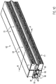
- the heating block or layer structure 46 is essentially composed of those shown in FIGS Figures 10 and 13
- the heating rods 62 shown are formed which are arranged in the receptacle 60 in a layered manner.
- the heating rods 62 consist of at least two corrugated fin elements 64 which accommodate a heat-generating element 66 between them.
- the corrugated rib elements consist of meandering bent sheet-metal strips 68 which are covered on one side by a sheet-metal cover 70 and are also held at the edge via a bent-over edge 72 of the sheet-metal cover 70.
- the other upper side of the meandering bent sheet metal strip 68 is free and is formed directly by bent free ends 74 of the sheet metal stiffener 68.
- the heating rod 62 shown are in the direction of passage of the air to be heated, ie at right angles to the surface of the frame 44 spanned by the outer sides 54, two corrugated rib elements 64 are provided next to one another.
- This arrangement of corrugated rib elements 64 provided one behind the other in the flow direction forms one layer.
- one corrugated rib element 64 is provided per plane E in each position identified by the reference symbol L.
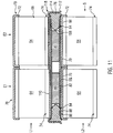
- S the direction of flow of the air flow to be heated is in Figure 11 drawn. This then first meets the first level E1, ie the corrugated fin elements 64 of the first layer L1 and the second layer L2 provided in the first plane and only then meets the corrugated fin elements 64 provided in the second plane E2.
- the corrugated fin elements 64 are in the flow direction S , ie at right angles to the outer side 54 defining the opening 56, arranged strictly one behind the other.
- the heat-generating element 66 forms a flat contact surface for the corrugated rib elements 64.
- the heat-generating element 66 consists of several layers one on top of the other.
- the heat-generating element 66 is constructed essentially symmetrically, with a positioning frame, identified by reference numeral 76, made of an electrically insulating material, in particular plastic, being provided in the center.
- the positioning frame 76 forms three receptacles 78 for PTC elements 80.
- a plurality of at least two PTC elements 80 are received in a receptacle 78.
- the two outer receptacles 78 each receive four PTC elements 80.
- Contact plates 82 rest on opposite sides of the PTC elements 80. These two contact plates 82 are of identical design and are formed from stamped, electrically conductive sheet metal.
- the contact plates 82 are placed on the PTC elements 80 as separate elements.
- These can also be vapor-coated Be provided electrode layer, as is common practice.
- the electrode layer is not, however, contact sheet 82 in the sense of the invention.
- the PTC element 80 assigned to a plane E1 lies within the front and back sides of the assigned corrugated rib elements 64. In other words, there is no PTC element 80 between two corrugated rib elements 64 provided in a layer L1. This creates a thermal interaction between the PTC elements of different levels E1, E2 avoided.
- the contact plates 82 are dimensioned in such a way that, although they are received within the positioning frame 76, they are arranged circumferentially at a distance from the positioning frame 78.
- the circumferential gap thus formed is in Figure 11 identified by reference number 84.
- the positioning frame 76 forms a circumferential sealing groove 86 into which an elastomeric adhesive edge 88 is filled as an annular bead.
- This adhesive edge 88 completely surrounds all of the receptacles 78 and is used to bond an insulating layer identified by reference numeral 90, which in the present case is formed from an insulating plastic film and which extends as far as an edge area of the positioning frame 76, in any case protruding over the adhesive edge 88 in the circumferential direction.
- connection pieces 92 are provided only on one end face of the positioning frame 76 and connecting pieces 92 formed in one piece thereon by virtue of its material, which surround a channel 94 for receiving pin-shaped contact elements 96 over the full circumference.
- the connecting pieces 92 carry sealing elements 98 formed from a thermoplastic elastomer or PTFE with a labyrinth-like sealing structure, which can be connected to the associated connecting piece 92 by injection molding or plugging.
- connection pieces 92 are provided on the end face of each positioning frame 76 for receiving two contact pins 96 for making electrical contact with the contact plates 82.
- the contact plates 82 have female clip element receptacles 100 produced by means of punching and bending, which are formed on laterally offset projections 102 of the contact plate 82, which projections 102 are inside end of the border given by the adhesive edge 88 and cover each of the associated clip openings 104, 106 formed by the positioning frame 76.
- clip webs 108 formed integrally thereon are provided by the material of the positioning frame 76. The design and diameter of these clip webs 108 correspond to the diameter of a contact pin 96.
- the contact pins 96 are exposed in the clip openings 104 and are connected to the female clip element receptacles 100 of the contact plates 82, whereas the female clip element receptacles 100 protrude into the clip openings 106 on the opposite side and are locked to the clip webs 108.
- the described clip connections can be made either by positioning the contact plates 82 in their installation position and then pushing the contact pins 96 through the channels 94 or by locking the female clip element receptacles 100 with the contact pins 96 already in position be realized.
- the heat-generating element 66 is provided with a sheet metal cover 110.
- This sheet metal cover 110 covers the entire insulating layer 90 assigned to the sheet metal cover 110 and has a circumferential edge 112 which rests non-positively on a circumferential edge surface 114 of the position frame 76 and accordingly secures the sheet metal cover 110 to the position frame 76 by means of a pretensioning force (cf. Fig. 11 ). Furthermore, the edge 112 ensures precise positioning of the sheet metal cover 110 relative to the outer circumference of the positioning frame.
- the sheet metal cover 110 has a slight conical widening at the free end of the edge 112, which acts as a funnel-shaped insertion opening for the positioning frame.
- the circumferential edge 112 is only perforated in the corner regions and at the level of the connecting pieces 92 and forms a one-sided shield for the heat-generating element 66.
- the channels 94 designed to match the contact pins 96 are widened radially to form a groove-shaped test channel 116.
- This test channel 116 extends from the front free end face of the connecting pieces 92 to the associated clip opening 104 and accordingly forms an external access to it the receptacles 78, which communicate with one another beneath the insulating layer 90 or the contact plates 82.
- the sheet metal cover 110 forms a flat contact surface for the circumferential edge 112 between the attachment areas 118 which are slightly bent upwards. These attachment areas 118 accordingly form a kind of centering for the corrugated rib elements 64 resting on the sheet metal cover 110 (see also FIG Figure 11 ).
- the layer structure 46 described above is held in the frame 44 under spring tension.
- the frame 44 has spring insertion openings 120 formed by the two frame elements 48, which are inserted into the Figures 4 and 5 can be seen and are exposed on the control side of the power section 2 when the auxiliary heater is not yet installed.
- tensionable spring elements 121 are introduced which go back to the applicant EP 2 298 582 and their disclosure content is incorporated into the disclosure of the present application by this reference.
- each of the frame elements 48 forms a respective holding element part 122.
- Each holding element part 122 formed by a frame element 48 is provided with an inclined ramp surface 124.
- the holding element parts 122 are designed such that when the frame 44 is joined, two holding element parts 122 each assigned to a frame element 48 form complete holding elements 126 with the frame element parts 122 of the other frame element 48 on opposite end sides. These holding elements 126 have a configuration that tapers towards the free end, so that the inclined ramp surfaces 24 are used for the rough positioning of the control part 4, namely a positioning opening 127 of the plastic housing element 10 relative to the power part 2 (cf. Fig. 5 ). Furthermore, after the frame elements 48 have been joined, transversely extending grooves 128 form a circumferentially closed bore 130 on the holding element parts 122 (cf. Fig. 4 ). A fastening screw can be introduced into this bore 130 through the fastening bore 42 of the metal shell 8 in order to position and fix the power part 2 on the control part 4 in order to realize a structural unit of power part 2 and control part 4.
- the plastic housing element 10 forms two cylindrical socket receptacles 132 for each heat-generating element 66, which are adapted in such a way that the connection stubs 42 together with the sealing elements 98 can each be introduced into associated socket receptacles 132 in a sealing manner.
- the nozzle receptacles 132 are conically widened at the end and initially have a widened cylinder section for receiving the sealing element 98 and a cylinder section with a smaller diameter located further inside, which holds the conically tapering connection nozzle 92 with little play and thus the deformation of the sealing element 98 continues limited to assembly.
- the contact pins 96 penetrate each contact surface elements 134 which are formed from sheet metal by punching and bending and group several contact pins 96 of the same polarity within the connection housing 6 so that they are assigned to a heating stage.
- the lower contact surface element is a first plus contact surface element 134
- the upper contact surface element is a minus contact surface element 136.
- the plastic housing element 10 takes on a further, second plus contact surface element 138.
- the minus contact surface element 136 and the plus contact surface elements 134, 138 are separated from one another by a separating web 140. This separating web 140 protrudes beyond a contact plane formed by the plastic housing element for the contact surface elements 134, 136, 138.
- FIG Figure 6 Surfaces of the plastic housing element 10 which define this contact plane are shown in FIG Figure 6 marked with reference numeral 142.
- the web 140 extends the leakage current path between the contact surface elements 134, 138 of the positive polarity and the contact surface element 136 of the negative polarity, so that there is no need to fear leakage currents between the two contacts.
- the air gap between the contact surface elements 134 and 136 or 138 and 136 is also relocated.
- the contact surface elements 134, 136, 138 have, between the contact pins 96, semicircular recesses 143 opening towards the separating web 140.
- the plastic housing element 10 forms locking projections 152 which are introduced into locking openings 154 of the contact surface elements 134, 136, 138, which are delimited on opposite sides by sharp-edged clamping segments 156 of the sheet metal material forming the contact surface elements 134, 136, 138. These clamping segments 156 accordingly claw onto the locking projections 152 and fix the contact surface elements 134, 136, 138 after being pushed onto the locking projections.
- the Figure 8 also shows the previously described heat sinks 32, which are exposed within the plastic housing element 10 and protrude over the top with a flat contact surface 158 over the separating web 140.
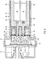
- FIG. 9 illustrates the installation of the heat sink 32 in the plastic housing element 10.
- This has - like Figure 8 - a plurality of locking posts 166 distributed on the circumference of a raised heat sink insertion opening 164 of the plastic housing element 10, which conically narrow the heat sink insertion opening 164 at the edge and form locking shoulders 168 which overlap a circumferential locking web 170 formed on the heat sink 32 and thus form-fit against being pushed out at the top and in the direction of the connection housing 6.
- the contour of the recesses 143 of the contact surface elements 134, 136, 138 corresponds to the contour of the heat sink insertion opening 164, so that its raised edge is closely delimited by the contact surface elements 134, 136, 138.
- the two plus contact surface elements 134, 138 are shaped identically so that they can be used optionally for the formation of the first or the second contact surface element 134 or 138.
- Latching web 170 On the opposite side of the locking shoulder 168 Latching web 170 is a sealing element 172 which surrounds the heat sink 32 circumferentially and on the underside facing away from the locking web 170 in the circumferential direction through Figure 9 non-recognizable webs is supported, so that the sealing element 72 cannot slip in the direction of the power part 2 through a sealing receptacle identified by reference numeral 174.
- This sealing receptacle 174 is formed in one piece by the plastic housing element 10 and extends the heat sink insertion opening 164.
- the sealing element is shown in an only slightly compressed configuration.
- the sealing element 172 can be compressed in the longitudinal direction of the sealing receptacle 174 such that the seal between the inner circumferential surface of the cylindrical sealing receptacle 174 and the outer circumferential surface of the cooling body 32 is lost.
- the sealing element 172 can be compressed by about 2/10 to 7/10 mm by moving the locking web 170 in the longitudinal extent of the sealing receptacle 174.
- the compensating movement is applied by screwing the pressure element 20 onto the fastening eyes 160 after the circuit board 18 has been mounted, which is provided with two semiconductor power switches 178 on its underside 176 facing the heat sink 32. Each circuit breaker 178 lies on the flat contact surface 158 of the associated heat sink 32.
- the circuit board has a bore 180 through which pressure webs 182 of the pressure element 20 protrude. These pressure webs 182 lie directly against the circuit breaker 178 and press it against the heat sink 32. Since the circuit breaker 178 can have considerable thickness tolerances due to the manufacturing process, the sealing element 172 provided in the exemplary embodiment allows compensation by the cooling body 32 retreating in the direction of the power section 2 without that the sealing of the heat sink 32 in the plastic housing element 10 is lost. As can be seen from the overall view, in particular FIGS. 4 and 9, after screwing against the plastic housing element 10, the pressure element 20 acts on both circuit breakers 176 and presses them against the heat sink 32 assigned to them.
- the power switch 178 is electrically insulated from the associated heat sink 32.
- the insulating layer 174 is a ceramic insulating layer. This insulating layer 184 also projects beyond the heat sink 32 to increase the creepage distance considerably in the width direction (cf. Figure 9 ).
- Contact surface elements 134, 136 are in contact with circuit board 18 via contact tongues 144, 146.
- a second positive contact tongue 186 protruding from the second contact surface element 138 (cf. Figure 4 ) connects the heating circuit formed by the second plus contact surface element 138 and the minus contact surface element 136 to the circuit board 18 (cf. Figure 4 ).
- the semiconductor power switch 178 makes contact with the circuit board 18 and switches the power current to the associated circuit. In the present case, two heating stages are implemented, each of which can be switched and controlled via one of the semiconductor power switches 178.
- the heat sink 32 is also held in a sealed manner in the heat sink insertion opening 164.
- the embodiment shows specifically Figure 9 , a situation in which the circuit breaker 178 has the smallest thickness within the conceivable tolerance range.
- the locking webs 170 are directly below the locking shoulders 168.
- there is no contact so that the compression force caused by the even slight compression of the sealing element 172 acts on the phase boundary between the heat sink 32 and the circuit breaker 178.
- This circuit breaker 178 is placed against the printed circuit board 18 on the underside 176, regardless of the thickness tolerance.
- the pressure element 20 with its pressure webs 82 only relieves the load on the circuit board 18, so that the circuit breaker 178 is not clamped over the circuit board 18, but only between the pressure element 20 and the heat sink 32 causing the bias voltage with the insulating layer 184 interposed.
- the position of the circuit breaker 178 and the circuit board 18 and the pressure element 20 does not change in the case of a circuit breaker 178 of greater strength. Rather, the heat sink 32 is pushed in the heat sink insertion opening 164 in the direction of the power part 2, so that the sealing element 172 is compressed more strongly while maintaining the sealing of the heat sink 32 and - compared to the illustration in FIG Figure 9 the locking webs 170 are arranged in a further lowered position, ie further spaced from the locking shoulders 168.
- the exemplary embodiment of an electrical heating device shown in the figures has heat-generating elements which are designed in a special way in order to lengthen creepage distances and to reduce the risk of leakage current transmission.
- This particular design is described below in particular with reference to Figures 2 and 11 clarified. So has - as in Figure 2 - each receptacle 78 given by a basically flat inner circumferential surface of the positioning frame 76 on opposite sides at least two projections marked with reference numeral 188 define within the receptacle 78 support points for one PTC element 80 each. These support points 188 prevent the PTC elements 80 bear directly on the smooth inner wall of the positioning frame 76 that defines the receptacle 78. Thus, the creepage distance from opposing surfaces of the PTC elements 80 is increased.
- the support points 188 are essentially pyramid-shaped and then have a tapering configuration. Furthermore, the surfaces of the support points 188 - like the sectional view according to FIG Figure 11 clarified - concave curved. The curvature of the surface also increases the creepage distance. The aforementioned circumferential gap 84 provided between the contact plates 82 and the positioning frame also contributes to increasing the creepage distances.
- the heat-generating elements 66 are particularly EMC-protected.
- the positioning frame 176 is basically completely surrounded by a shield, which is formed on the one hand by the sheet metal cover 110 of the positioning frame 76 and on the other hand by the sheet metal cover 70 of the corrugated rib elements 64. How Figure 11 As illustrated, only a small gap at the edge remains between the various covers 70, 110. Otherwise, the PTC elements 80 are completely enclosed by a metallic shield. Accordingly, the heat generating elements 66 cannot emit any substantial electromagnetic radiation.
- corrugated rib elements 64 are also connected to one another via latching elements formed on the metal shell 8, which are not shown in the drawing. however, can be designed as that which goes back to the applicant EP 2 299 201 A1 describes, the disclosure of which is included in the disclosure content of this application. It is only important that the metal shell 8 forms projections that are electrically connected to it and that make contact with the corrugated rib elements 64 in such a way that all of the corrugated rib elements 64 are directly or indirectly electrically connected to the metal shell 8 and connected to ground.
- the exemplary embodiment discussed above has heat-generating elements 66, the receptacle 78 of which is hermetically sealed from the environment, so that moisture and contamination cannot reach the PTC elements 80.
- all the heat-generating elements 66 are also inserted into the connection housing 6 in a sealing manner.
- a test bell is placed on its free end, which is usually closed by the housing cover 12, after the power unit 2 has been joined to the plastic housing element 10, and is applied to the free edge of the plastic housing element 10 in a sealing manner.
- the part of the electrical heating device connected to it is placed under increased hydrostatic pressure via this test bell, for example by compressed air. A certain pressure level is maintained and it is checked whether this is reduced by possible leaks over time. If this is not the case, the component is rated as good.
- the power part 2 is first produced separately.
- the heat generating elements 66 are assembled.
- the sheet metal cover 110 can close the underside and thus the underside of the positioning frame 76, which is open on one side, after the insulating layer 90 assigned to the sheet metal cover 110 has been glued on, so that the PTC elements 80 are inserted from the other side and the assigned contact sheet 82 is then placed on them can to finally place the insulating layer 90 on it and to be sealed against the positioning frame 76 via the adhesive edge 88.
- the heat-generating elements 66 prepared in this way are inserted into a frame element 48 of the frame 44, to be precise in each case alternating with the arrangement of corrugated rib elements 64
- Figure 4 results, there are usually two corrugated rib elements 64 between two heat-generating elements 66.
- a layer L of corrugated fin elements rests on each side of a heat-generating element 66.
- the comparison between Figure 4 and Figure 11 further clarifies that in the embodiment according to Figure 4 at least two corrugated rib elements 64 are arranged in one layer.
- the frame 44 is closed by placing and locking the other frame element 48. Thereafter, the respective spring elements 121 are inserted between the layer structure 46 and an outer edge of the receptacle 60 created by the frame 44 via the spring insertion openings 120. Finally, the spring elements 121 are braced against one another, as shown in FIG EP 2 298 582 is described.
- the power part 2 prepared in this way is then joined to the metal shell 8 and the plastic housing element 10. Due to their pointed configuration, the ramp surfaces 124 serve as positioning and centering aids, so that the holding element 126 can be effectively introduced into the positioning opening 127.
- the holding element 126 is usually leading relative to the contact pins 96, so that rough positioning is first carried out via the holding elements 126 and then the contact pins 96 are introduced into the cylindrical receiving sockets 132.
- FIGs 12 to 15 illustrate a further aspect of the present invention, which consists in the fact that the corrugated rib elements 64 provided one behind the other in a layer L in the flow direction are provided offset from one another in a direction transverse to the flow direction S but in their corresponding installation plane within the layer structure 46.
- the meandering bent sheet metal strips 68 of the corrugated rib elements 64 provided one behind the other in a position L can be seen.
- These are identified with reference symbols 68.1 and 68.2 and can thus be distinguished. It the result is that the air to be heated flowing at right angles to the plane of the drawing flows toward almost completely separate, meandering sheet metal strips 68.1 and 68.2.
- the rear sheet metal strip element is not shaded by the front one. There is good heat transfer.
- the air flow S to be heated is shifted at the transition from the first level E1 to the second level E2, which is associated with a turbulent flow, which also improves the heat transfer.
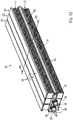
- the Figures 13 to 15 show a second embodiment corresponding to FIGS Figures 10 to 12 .
- the exemplary embodiment shown of a heating rod differs from the exemplary embodiment discussed above only in that three corrugated rib elements 64 are arranged one behind the other in a layer L1 or L2. There, too, corrugated rib elements 64 arranged in a plane E1, E2, E3 are each strictly assigned to a PTC element 80. How Figure 15 shows, the air flowing through the heating rod 62 is shifted several times.
- the labyrinth of sheet metal strips 68.1, 68.2 and 68.3 formed by the meandering sheet metal strips 68 provided offset from one another leads to very good heat transfer and power yield.
- Figure 16 shows the frame elements 48 already described above and an intermediate frame element 190 which is provided with female and male latching elements 50, 52 corresponding to the frame elements 48, so that the intermediate frame element 190 can be latched between the frame elements 48 in a simple manner.
- the receptacle 60 provided in the frame for the layer structure 46 is thus enlarged by precisely the width that a plane of corrugated rib elements 46 contributes.
- the heat-generating elements 66 are each designed uniformly, ie whether two PTC elements 80 are arranged one behind the other in the flow direction S or three PTC elements 80; the PTC elements 80 are each received within a uniform position frame 76.
- the corrugated fin elements 64 are, however, identical.
- An identical plastic housing element 10 can be used for each of the heating rods 62 provided with three corrugated rib elements 64 arranged next to one another and the heating rods 62 provided with two corrugated rib elements 64. Because the intermediate frame element 190 also has holding element parts 122, which with the holding element parts 122 one of the frame elements 48 cooperate in order to form a complete holding element 126, via which the widened frame 44 also follows Figure 16 can be connected to the plastic housing element 10. If, for example, four corrugated rib elements 64 form a heating rod one behind the other in the direction of flow, a second intermediate frame element 190 can be installed in the frame 44.
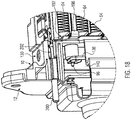
- FIGS 17 and 18th show an embodiment that is slightly modified compared to the embodiment described above.
- the same components are identified by the same reference symbols.
- the one in the Figures 17 and 18th The embodiment shown is in particular the previously described shielding housing element 8 turned away.
- a shielding contact plate 192 is provided, which rests in a form-fitting manner on outer contact surfaces of the plastic housing element 10. This also forms bulges 194 in which shielding contact tongues 196 of shielding contact plate 192 are received.
- the shielding contact tongues 196 are each provided at the level of a heat-generating element 66 and contact the edge 112 of this element 66.
- the shielding contact sheet 192 forms spring webs 198 formed by punching and bending, each of which rests on the end face of one of the heat sinks 32 and makes contact with it . How in particular Figure 18 As can be seen, the shielding contact plate 192 closely surrounds the cylindrical socket receptacle 132, which is formed by the plastic housing element 10.
- connection bolt 200 which is grounded.
- This connecting bolt 200 is held in the plastic housing element 10, for example by overmolding.
- the shielding contact plate 192 clipped to the plastic housing element 10 forms a bolt receptacle 202 which is formed by punching and bending and which rests in an electrically conductive manner on the connecting bolt 200 under elastic circumferential tension.
- the heat sinks 32 are connected to ground via the shielding contact sheet 192, so that the reliable electrical insulation can be checked between the circuit breaker 178 and the heat sink 32 by monitoring the ground potential tapped at the connecting bolt 200. Any defect in the electrical insulation can be detected and output in order to prevent the maintenance potential from suffering an electric shock during maintenance work on the electrical heating device if there is insufficient electrical insulation.
Landscapes
- Air-Conditioning For Vehicles (AREA)
- Direct Air Heating By Heater Or Combustion Gas (AREA)
Description
Die vorliegende Erfindung betrifft ein Wärme erzeugendes Element mit den oberbegrifflichen Merkmalen von Anspruch 1 und eine elektrische Heizvorrichtung mit den oberbegrifflichen Merkmalen von Anspruch 3.The present invention relates to a heat-generating element with the preamble features of
Solche Wärme erzeugenden Elemente sind allgemein bekannt als Bestandteil einer elektrischen Heizvorrichtung insbesondere zur Lufterwärmung in einem Kraftfahrzeug, die mit der vorliegenden Erfindung ebenfalls weitergebildet werden soll. Das Wärme erzeugende Element bildet eine Lage eines Schichtaufbaus, welches üblicherweise an beiden Seiten des Wärme erzeugenden Elementes anliegende Wellrippenelemente umfasst. Dieser Schichtaufbau hat üblicherweise eine Mehrzahl von jedenfalls in einer Ebene übereinander geschichteten Lagen von Wellrippenelementen und Wärme erzeugenden Elementen.Such heat-generating elements are generally known as a component of an electrical heating device, in particular for heating the air in a motor vehicle, which is also to be developed further with the present invention. The heat-generating element forms a layer of a layer structure which usually comprises corrugated fin elements resting on both sides of the heat-generating element. This layer structure usually has a plurality of layers of corrugated fin elements and heat-generating elements that are stacked one on top of the other in one plane.
Ein gattungsgemäßes Wärme erzeugendes Element ist aus
Elektrische Heizvorrichtungen umfassend ein Wärme erzeugendes Element der gattungsgemäßen Art führen mitunter zu elektromagnetischen Störungen, die insbesondere innerhalb eines Kraftfahrzeuges sehr unerwünscht sind, da sich diese beispielsweise beim Betrieb eines Radios akustisch im Fahrzeuginnenraum bemerkbar machen.Electrical heating devices comprising a heat-generating element of the generic type sometimes lead to electromagnetic interference, which is particularly undesirable inside a motor vehicle, since this is acoustically noticeable in the vehicle interior, for example when a radio is operated.
So liegt der vorliegenden Erfindung das Problem zugrunde, ein Wärme erzeugendes Element insbesondere für eine elektrische Heizvorrichtung für ein Kraftfahrzeug sowie eine elektrische Heizvorrichtung anzugeben, welche in verbesserter Weise der EMV-Problematik Rechnung tragen.The present invention is based on the problem of specifying a heat-generating element, in particular for an electrical heating device for a motor vehicle, as well as an electrical heating device, which take account of the EMC problem in an improved manner.
Zur Lösung dieses Problems wird mit der vorliegenden Erfindung ein Wärme erzeugendes Element mit den Merkmalen von Anspruch 1 vorgeschlagen.To solve this problem, the present invention proposes a heat-generating element having the features of
Das erfindungsgemäße Wärme erzeugende Element hat in an sich bekannter Weise einen Positionsrahmen. Dieser Positionsrahmen ist üblicherweise aus einem elektrisch nicht leitenden Material hergestellt und bildet zumindest eine, üblicherweise mehrere Aufnahmen für wenigstens ein PTC-Element aus. In einer Aufnahme können auch mehrere PTC-Elemente vorgesehen sein. An gegenüberliegenden Seiten des bzw. der PTC-Elemente liegen Kontaktbleche an, die mit unterschiedlicher Polarität bestromt werden. Solche Kontaktbleche sind üblicherweise durch Stanzen gegebenenfalls Biegen aus einem Blechstreifen gebildet.The heat generating element according to the invention has a position frame in a manner known per se. This position frame is usually made of an electrical one Manufactured non-conductive material and forms at least one, usually several receptacles for at least one PTC element. Several PTC elements may be provided. On opposite sides of the PTC element or elements there are contact plates which are supplied with current with different polarity. Such contact sheets are usually formed from a sheet metal strip by punching, if necessary bending.
Das erfindungsgemäße Wärme erzeugende Element hat zusätzlich eine mit dem Positionsrahmen verbundene Blechabdeckung. Diese Blechabdeckung ist üblicherweise elektrisch isolierend von den beiden Kontaktelementen vorgesehen. Sie kann durch eine Luftstrecke gegenüber dem zugeordneten Kontaktblech isoliert sein, d.h. nicht auf dem Kontaktblech, sondern lediglich dem Positionsrahmen aufliegen. Üblicherweise und insbesondere mit Blick auf eine gute Wärmeübertragung liegt indes die Blechabdeckung mittelbar an dem ihr zugeordneten Kontaktblech an. Eine mittelbare Anlage bedingt regelmäßig die Zwischenschaltung einer Isolierschicht zwischen der Blechabdeckung und dem zugeordneten Kontaktblech. Diese Isolierlage kann aus einer Kunststofffolie und/oder Keramikschicht gebildet sein. Die Isolierlage kann auch durch Aufspritzen von Kunststoff und/oder Keramik auf die Außenfläche des Kontaktbleches und/oder die Innenfläche der Blechabdeckung aufgebracht sein.The heat generating element according to the invention also has a sheet metal cover connected to the positioning frame. This sheet metal cover is usually provided in an electrically insulating manner from the two contact elements. It can be isolated from the associated contact plate by an air gap, i.e. do not rest on the contact plate, but only on the positioning frame. Usually, and especially with a view to good heat transfer, the sheet metal cover rests indirectly on the contact sheet assigned to it. An indirect system usually requires the interposition of an insulating layer between the sheet metal cover and the associated contact sheet. This insulating layer can be formed from a plastic film and / or ceramic layer. The insulating layer can also be applied by spraying plastic and / or ceramic onto the outer surface of the contact plate and / or the inner surface of the sheet metal cover.
Die Blechabdeckung kann auf jede beliebige Art und Weise mit dem Positionsrahmen verbunden sein, beispielsweise durch Umspritzen mit diesen zu einer Einheit verbunden oder aber nachträglich an einem zunächst durch Spritzgießen vorbereiteten Positionsrahmen befestigt werden.The sheet metal cover can be connected to the position frame in any desired manner, for example connected to it to form a unit by overmolding, or it can be subsequently attached to a position frame initially prepared by injection molding.
Bei dem erfindungsgemäßen Wärme erzeugenden Element bildet die Blechabdeckung eine Abschirmung für das Wärme erzeugende Element aus. Dementsprechend begründet eine das Wärme erzeugende Element umfassende elektrische Heizvorrichtung im verminderten Maße EMV-Probleme. Es können an gegenüberliegenden Seitenflächen und zu jedem der Kontaktbleche vorzugsweise unter Zwischenlage einer Isolierschicht jeweils daran anliegende Blechabdeckungen vorgesehen sein, so dass das Wärme erzeugende Element an seiner Außenseite insgesamt von Blechen abgedeckt ist. Die Blechabdeckung bildet üblicherweise die Anlagefläche für das bzw. die Wellrippenelemente aus. Als Wellrippenelement im Sinne der vorliegenden Erfindung ist dabei nicht zwingend allein durch einen mäandrierend umbogenen Blechstreifen gegeben. Das Wellrippenelement kann auch als Strangpressprofil aus Aluminium hergestellt sein. Die einzelnen Stege eines solchen Profils bilden Wellrippen des besagten Wellrippenelementes aus.In the case of the heat-generating element according to the invention, the sheet metal cover forms a shield for the heat-generating element. Accordingly, an electric heater comprising the heat generating element causes less EMC problems. On opposite side surfaces and on each of the contact sheets, preferably with an insulating layer in between, sheet metal covers can be provided so that the heat-generating element is covered by sheet metal on its outside. The sheet metal cover usually forms the contact surface for the corrugated rib element or elements. The corrugated rib element in the sense of the present invention is not necessarily given by a meandering sheet metal strip. The corrugated rib element can also be produced as an extruded profile made of aluminum. The individual webs of such a profile form corrugated ribs of the said corrugated rib element.
Gemäß der vorliegenden Erfindung hat die Blechabdeckung einen den Positionsrahmen im Wesentlichen vollumfänglich umgebenden Rand. Dieser Rand erstreckt sich üblicherweise über die gesamte Höhe des Positionsrahmen, d.h. bis zu oder gar über die Ebene, die durch das an der gegenüberliegenden Seite angeordnete Kontaktblech definiert ist. Dies gilt jedenfalls für den Fall, bei dem auch der dem Kontaktblech mit dem umfänglich umgebenen Rand gegenüberliegenden Seite ein ebenes Kontaktblech zur weiteren Abschirmung des Wärme erzeugenden Elementes vorgesehen ist. Selbstverständlich ist es möglich, an gegenüberliegenden Seiten des Wärme erzeugenden Elementes jeweils Kontaktbleche mit einem den Positionsrahmen umgebenden Rand vorzusehen und zwar so, dass die jeweiligen Randstücke der Kontaktbleche komplementär zueinander sind mit dem Ziel, dass der Positionsrahmen durch die Blechabdeckungen nicht nur ober- bzw. unterseitig vollständig abgeteilt ist, sondern auch an seinem Außenrand im Wesentlichen vollumfänglich von der durch die Blechabdeckungen definierten Abschirmung umgeben ist.According to the present invention, the sheet metal cover has an edge that essentially completely surrounds the positioning frame. This edge usually extends the full height of the position frame, i. up to or even above the plane that is defined by the contact plate arranged on the opposite side. This applies in any case to the case in which a flat contact sheet is also provided for further shielding of the heat-generating element on the side opposite the contact sheet with the circumferentially surrounded edge. Of course, it is possible to provide contact plates on opposite sides of the heat-generating element with an edge surrounding the position frame in such a way that the respective edge pieces of the contact plates are complementary to one another, with the aim of ensuring that the position frame is not only above or below the sheet metal covers. is completely partitioned on the underside, but is also essentially completely surrounded on its outer edge by the shielding defined by the sheet metal covers.
Im Hinblick auf eine möglichst einfache Herstellung des Wärme erzeugenden Elementes ist es indes zu bevorzugen, lediglich eine Blechabdeckung mit einem den Positionsrahmen im Wesentlichen umfänglich umgebenden Rand auszuformen. Dieser Rand ist vorzugsweise mit dem Positionsrahmen verclipst, so dass bei der Montage des Wärme erzeugenden Elementes zunächst einseitig die Blechabdeckung gegebenenfalls unter vorherigem Einbringen der Isolierlage und des Kontaktbleches an den Positionsrahmen angeclipst werden kann. Danach kann der Positionsrahmen mit seiner noch offenen Seite nach oben angeordnet und in die Aufnahme(n) das bzw. die PTC-Elemente eingelegt werden. Die mit dem Positionsrahmen verclipste Blechabdeckung bildet dementsprechend einen fest mit dem Positionsrahmen verbundenen Boden, der das Auflegen der jeweiligen Schichten in dem Wärme erzeugenden Element vereinfacht. Als Schichten sind dabei insbesondere das bzw. die PTC-Elemente sowie das auf der der Blechabdeckung gegenüberliegenden Seite vorgesehene Kontaktblech, gegebenenfalls eine diesem zugeordnete äußere Isolierlage zu verstehen.With regard to the simplest possible production of the heat-generating element, however, it is preferable to only form a sheet metal cover with an edge that essentially surrounds the positioning frame. This edge is preferably clipped to the position frame, so that when the heat-generating element is installed, the sheet metal cover can be clipped onto the position frame on one side, if necessary with prior introduction of the insulating layer and the contact sheet. The positioning frame can then be arranged with its side that is still open and the PTC element (s) inserted into the receptacle (s). The sheet metal cover clipped to the positioning frame accordingly forms a base which is firmly connected to the positioning frame and which simplifies the placement of the respective layers in the heat-generating element. Layers are in particular the PTC element (s) and the contact sheet provided on the side opposite the sheet metal cover, possibly an outer insulating layer assigned to it.
Gemäß einem nebengeordneten Aspekt der vorliegenden Erfindung schlägt diese eine elektrische Heizvorrichtung mit den Merkmalen von Anspruch 3 vor, welche weniger anfällig für EMV-Probleme ist. Bei dieser elektrischen Heizvorrichtung ist beidseitig des Wärme erzeugenden Elementes jeweils eine Blechabdeckung vorgesehen. Die Blechabdeckung befindet sich zwischen den Wellrippenelementen und dem Kontaktblech. Regelmäßig ist zwischen der Blechabdeckung und dem zugeordneten Kontaktblech jeweils eine Isolierlage vorgesehen. Eine gattungsgemäße elektrische Heizvorrichtung ist aus
Mit Blick auf eine einfache und wirtschaftliche Montage bei einem kompakten Aufbau der elektrischen Heizvorrichtung wird gemäß einer bevorzugten Weiterbildung der vorliegenden Erfindung vorgeschlagen, dass die auf der einen Seite angeordnete Blechabdeckung dem Wärme erzeugenden Element zugeordnet ist und die auf der gegenüberliegenden, d.h. anderen Seite angeordnete Blechabdeckung dem Wellrippenelement. Die dem Wärme erzeugenden Element zugeordnete Blechabdeckung ist üblicherweise mit dem Positionsrahmen fest oder lösbar verbunden, vorzugsweise mit diesem über einen den Positionsrahmen umgebenden Rand verclipst. Die dem Wellrippenelement zugeordnete Blechabdeckung kann mit den Wellrippen des Wellrippenelementes verlötet oder auf andere Weise verbunden sein, beispielsweise durch Umbördeln mit dem Wellrippenelement verbunden sein. Ein solches Umbörderln mag zu einer Clipsverbindung zwischen dem Wellrippenelement und der zugeordneten Blechabdeckung führen. Jedenfalls ist bei der diskutierten Weiterbildung eine Blechabdeckung üblicherweise fest dem Positionsrahmen und die andere Blechabdeckung fest dem Wellrippenelement zugeordnet, so dass bei einer Montage des Schichtaufbaus innerhalb des Rahmens lediglich eine reduzierte Anzahl von Teilen gehandhabt werden muss, um eine gegenüber EMV-Problemen verbessert geschützte elektrische Heizvorrichtung herzustellen.With a view to simple and economical assembly with a compact construction of the electrical heating device, it is proposed according to a preferred development of the present invention that the sheet metal cover arranged on one side is assigned to the heat-generating element and that on the opposite, i.e. sheet metal cover arranged on the other side of the corrugated fin element. The sheet metal cover assigned to the heat-generating element is usually fixedly or detachably connected to the position frame, preferably clipped to it via an edge surrounding the position frame. The sheet metal cover assigned to the corrugated fin element can be soldered to the corrugated fins of the corrugated fin element or connected in some other way, for example connected to the corrugated fin element by crimping. Such a flanging may lead to a clip connection between the corrugated rib element and the associated sheet metal cover. In any case, in the further development discussed, one sheet metal cover is usually permanently assigned to the positioning frame and the other sheet metal cover is permanently assigned to the corrugated rib element, so that when the layer structure is assembled within the frame, only a reduced number of parts have to be handled in order to provide an electrical one that is better protected against EMC problems Manufacture heating device.
Mit Blick auf eine verbesserte Erwärmung der Luft wird gemäß einer bevorzugten Weiterbildung der vorliegenden Erfindung vorgeschlagen, dass der Heizblock mehrere in Durchströmungsrichtung des zu erwärmenden Mediums hintereinander vorgesehene Wellrippenelemente umfasst. Diese Wellrippenelemente liegen jeweils in identischen Ebenen hintereinander angeordnet. Sie sind üblicherweise versetzt zueinander vorgesehen, so dass die Wellrippen des zuerst angeströmten Wellrippenelementes die Wellrippen des nachfolgenden Wellrippenelementes nicht vollständig abdecken bzw. abschirmen. Vielmehr liegen die Wellrippen des in Strömungsrichtung zweiten Wellrippenelementes bei einer Projektion auf die hintereinander angeordneten Wellrippenelemente in Strömungsrichtung des zu erwärmenden Mediums frei. Bei dieser bevorzugten Weiterbildung umfasst die auf der anderen Seite vorgesehene Blechabdeckung mehrere Abdeckelemente. Jedes der Abdeckelemente ist einem einzigen Wellrippenelement zugeordnet. Die in Strömungsrichtung des zu erwärmenden Mediums hintereinander angeordneten Abdeckelemente bilden dementsprechend die Blechabdeckung auf der Wellrippenseite aus. Üblicherweise stoßen die Abdeckelemente bei der beschriebenen Anordnung der Wellrippenelemente in Strömungsrichtung hintereinander unmittelbar aneinander an, so dass sich zwischen den einzelnen Wellrippenelementen keine Störung der Abschirmung auf der Wellrippenseite ergibt.With a view to improved heating of the air, it is proposed according to a preferred development of the present invention that the heating block have several corrugated rib elements provided one behind the other in the direction of flow of the medium to be heated includes. These corrugated rib elements are each arranged one behind the other in identical planes. They are usually provided offset with respect to one another, so that the corrugated ribs of the corrugated rib element against which the flow comes first do not completely cover or shield the corrugated ribs of the subsequent corrugated rib element. Rather, the corrugated fins of the second corrugated fin element in the flow direction are exposed when projected onto the corrugated fin elements arranged one behind the other in the flow direction of the medium to be heated. This preferred development includes the sheet metal cover provided on the other side has several cover elements. Each of the cover elements is assigned to a single corrugated rib element. The cover elements arranged one behind the other in the direction of flow of the medium to be heated accordingly form the sheet metal cover on the corrugated rib side. In the described arrangement of the corrugated rib elements, the cover elements usually abut one another directly one behind the other in the flow direction so that there is no interference with the shielding on the corrugated rib side between the individual corrugated rib elements.
Gemäß der vorliegenden Erfindung hat die elektrische Heizvorrichtung ein Anschlussgehäuse, welches an einem stirnseitigen Ende des Schichtaufbaus vorgesehen ist. Ein solches Anschlussgehäuse nimmt üblicherweise die elektrischen Anschlusselemente zu ausgewählten, üblicherweise sämtlichen Kontaktblechen in sich auf, so dass die einzelnen Wärme erzeugenden Elemente in dem Anschlussgehäuse elektrisch angeschlossen sind. Das Anschlussgehäuse kann auch eine Steuervorrichtung zur Ansteuerung und Regelung der einzelnen Wärme erzeugenden Elemente haben. Diese können zu unterschiedlichen Heizstufen gruppiert und zusammengefasst sein. Das Anschlussgehäuse hat gemäß einer bevorzugten Weiterbildung der vorliegenden Erfindung ein Abschirmgehäuseelement. Dieses Abschirmgehäuseelement kann ein das Gehäuse ganz oder teilweise ausbildendes Element sein, welches aus einem metallischen Werkstoff hergestellt ist. Alternativ kann das Abschirmgehäuseelement auch lediglich als Metall- bzw. Blechschale ausgeformt sein, welches die das Gehäuse bildenden und die Abdichtung der in dem Anschlussgehäuse vorgesehenen Komponenten, insbesondere der Steuerkomponenten bewirkenden Gehäuseschalenelemente abschirmend umgibt. Das Abschirmgehäuseelement ist gemäß der bevorzugten Weiterbildung elektrisch leitend mit den Blechabdeckungen verbunden. Dadurch ergibt sich eine einheitliche Abschirmung, die sowohl die Wärme erzeugenden Elemente des Schichtaufbaus wie auch das Anschlussgehäuse umgibt und dementsprechend auch EMV-Störungen, die von dem Anschlussgehäuse ausgehen können, abschirmt. Des Weiteren bietet die Weiterbildung die Möglichkeit, die Abschirmung über das Anschlussgehäuse zu erden.According to the present invention, the electrical heating device has a connection housing which is provided at a front end of the layer structure. Such a connection housing usually accommodates the electrical connection elements for selected, usually all, contact plates, so that the individual heat-generating elements in the connection housing are electrically connected. The connection housing can also have a control device for activating and regulating the individual heat-generating elements. These can be grouped and combined to form different heating levels. According to a preferred development of the present invention, the connection housing has a shielding housing element. This shielding housing element can be an element which completely or partially forms the housing and which is made from a metallic material. Alternatively, the shielding housing element can also be formed merely as a metal or sheet metal shell, which surrounds in a shielding manner the housing shell elements forming the housing and sealing the components provided in the connection housing, in particular the control components. According to the preferred development, the shielding housing element is electrically conductively connected to the sheet metal covers. This results in a uniform shielding that surrounds both the heat-generating elements of the layer structure and the connection housing and accordingly also shields EMC interference that may arise from the connection housing. The further training also offers the option of grounding the shielding via the connection housing.
Das Abschirmgehäuseelement ist vorzugsweise leitend mit den Blechabdeckungen verclipst. Dementsprechend sind Clipsstege vorgesehen, welche das Abschirmgehäuseelement elektrisch leitend mit den Blechabdeckungen verbindet. Dabei muss die elektrisch leitende Verbindung nicht unmittelbar zwischen dem Abschirmgehäuseelement und der Blechabdeckung erfolgen. Vielmehr kann - da die Wellrippenelemente üblicherweise unmittelbar, d.h. elektrisch leitend mit den zugeordneten Blechabdeckungen verbunden sind - die elektrische Kontaktierung zwischen dem Abschirmgehäuseelement und der Blechabdeckung auch über das Wellrippenelement erfolgen.The shielding housing element is preferably clipped to the sheet metal covers in a conductive manner. Accordingly, clip webs are provided which connect the shielding housing element to the sheet metal covers in an electrically conductive manner. The electric Conductive connection is not made directly between the shielding housing element and the sheet metal cover. Rather, since the corrugated rib elements are usually directly, ie electrically conductively connected to the associated sheet metal covers, the electrical contact between the shielding housing element and the sheet metal cover can also be made via the corrugated rib element.
Das Abschirmgehäuseelement kann als gegossenes metallisches Gehäuse ausgeformt sein. Alternativ kann das Abschirmgehäuseelement auch als Kunststoffgehäuseelement ausgebildet sein, welches zur Abschirmung innerhalb einer Blechschale aufgenommen ist.The shielding housing element can be formed as a cast metallic housing. Alternatively, the shielding housing element can also be designed as a plastic housing element, which is received within a sheet metal shell for shielding.
Gemäß einer bevorzugten Weiterbildung der vorliegenden Erfindung bildet das Abschirmgehäuseelement Ein- und Austrittsöffnungen für einen gegenüber dem Inneren des Anschlussgehäuses abgedichteten Kühlkanal aus. In diesem Kühlkanal befindet sich üblicherweise zumindest ein Kühlkörper, der zur Kühlung eines in dem Anschlussgehäuse aufgenommenen Leistungsschalters vorgesehen ist und dessen Verlustleistung an das zu erwärmende Medium in Form von Wärme abgibt.According to a preferred development of the present invention, the shielding housing element forms inlet and outlet openings for a cooling channel that is sealed off from the interior of the connection housing. In this cooling channel there is usually at least one heat sink which is provided for cooling a circuit breaker accommodated in the connection housing and which gives off its power loss to the medium to be heated in the form of heat.
Mit ihrem weiteren, nebengeordneten Aspekt gibt die vorliegende Erfindung eine elektrische Heizvorrichtung der oben genannten Art an, die ein elektrische Kontaktelemente von mehreren Wärme erzeugenden Elementen aufnehmendes Anschlussgehäuse hat. Das Anschlussgehäuse dient dabei regelmäßig dem Anschluss von ausgewählten, mitunter sämtlichen Kontaktblechen an eine Steuereinrichtung, die in dem Anschlussgehäuse aufgenommen sein kann. Diese Steuereinrichtung umfasst üblicherweise eine bestückte Leiterplatte bzw. Platine. Häufig ist diese heutzutage mit zumindest einem Halbleiter-Leistungsschalter bestückt, der die Wärme erzeugenden Elemente ansteuert und dabei Verlustleistung erzeugt, die regelmäßig durch Kühlung des Leistungsschalters abgeführt werden muss. Ein Anschlussgehäuse kann aber auch alternativ oder zusätzlich Leiterplatten oder Leiterelemente umfassen, durch welche die angeschlossenen Wärme erzeugenden Elemente kontaktiert bzw. gruppiert werden.With its further, subordinate aspect, the present invention specifies an electrical heating device of the type mentioned above, which has a connection housing which receives electrical contact elements from several heat-generating elements. The connection housing regularly serves to connect selected, sometimes all, contact plates to a control device that can be accommodated in the connection housing. This control device usually comprises an assembled printed circuit board or circuit board. Nowadays, this is often equipped with at least one semiconductor power switch, which controls the heat-generating elements and thereby generates power loss that has to be dissipated regularly by cooling the power switch. A connection housing can, however, alternatively or additionally comprise circuit boards or conductor elements through which the connected heat-generating elements are contacted or grouped.
Mit Blick auf die gegebene EMV-Problematik wird mit der vorliegenden Erfindung vorgeschlagen, das Anschlussgehäuse mit einem Abschirmgehäuseelement, einem in dem Abschirmgehäuseelement aufgenommenen Kunststoffgehäuseelement und einem an das Abschirmgehäuseelement und/oder das Kunststoffgehäuseelement dichtend anlegbarem Gehäusedeckelelement auszubilden. Das Abschirmgehäuseelement ist dabei üblicherweise wie auch das Gehäusedeckelelement als Abschirmung ausgebildet, d.h. aus Metall bzw. mit einer Metalleinlage ausgeformt. Dementsprechend schirmen Abschirmgehäuseelement und Gehäusedeckelelement das Innere des Anschlussgehäuses ab. Das Abschirmgehäuseelement und/oder das Gehäusedeckelelement sind dabei üblicherweise mit der Abschirmung des Schichtaufbaus, beispielsweise einer Blechabdeckung des Wärme erzeugenden Elementes und/oder den Wellrippenelementen des Schichtaufbaus elektrisch verbunden, so dass die elektrische Heizvorrichtung eine einheitliche Abschirmung aufweist.With a view to the given EMC problem, the present invention proposes that the connection housing with a shielding housing element, a plastic housing element received in the shielding housing element and a sealing housing element and / or the plastic housing element be applied Form housing cover element. The shielding housing element, like the housing cover element, is usually designed as a shielding, that is to say formed from metal or with a metal insert. Correspondingly, the shielding housing element and the housing cover element shield the interior of the connection housing. The shielding housing element and / or the housing cover element are usually electrically connected to the shielding of the layer structure, for example a sheet metal cover of the heat-generating element and / or the corrugated rib elements of the layer structure, so that the electrical heating device has a uniform shield.
Das Kunststoffgehäuseelement ist entsprechend angepasst und ausgebildet zur Aufnahme bzw. Halterung der Steuereinrichtung und/oder zur Halterung von den Anschluss der elektrischen Heizvorrichtung bewirkenden Anschlusselementen. Über diese elektrischen Anschlusselemente kann die elektrische Heizvorrichtung direkt an eine Leistungsversorgung angeschlossen sein. Alternativ können entsprechende Anschlusselemente in dem Kunststoffgehäuseelement lediglich gehalten und über das Gehäusedeckelelement an der Außenseite des Anschlussgehäuses zugänglich gemacht werden. Das Kunststoffgehäuseelement dient dabei der isolierenden Aufnahme der den Leistungsstrom leitenden und/oder schaltenden Elemente der Steuereinrichtung bzw. von Kontaktflächenelementen, welche üblicherweise die Anschlusselemente zu einigen oder allen Wärme erzeugenden Elementen kontaktieren bzw. gruppieren.The plastic housing element is correspondingly adapted and designed for receiving or holding the control device and / or for holding connection elements which effect the connection of the electrical heating device. The electrical heating device can be connected directly to a power supply via these electrical connection elements. Alternatively, corresponding connection elements can only be held in the plastic housing element and made accessible via the housing cover element on the outside of the connection housing. The plastic housing element serves to isolate the elements of the control device that conduct and / or switch the power flow or contact surface elements which usually contact or group the connection elements to some or all of the heat-generating elements.
Durch diese Weiterbildung kann dementsprechend zum einen eine einfache Abschirmung des Anschlussgehäuses gegebenenfalls unter Einbeziehung des Schichtaufbaus bewirkt werden. Durch das Kunststoffgehäuseelement wird andererseits eine differenzierte Ausgestaltung zur Aufnahme und Halterung von elektrisch leitenden Komponenten geschaffen. Da das Kunststoffgehäuseelement in das Abschirmgehäuseelement eingesetzt ist, sind auch die in dem Kunststoffgehäuseelement aufgenommenen elektrischen oder elektronischen Komponenten abgeschirmt.With this development, on the one hand, simple shielding of the connection housing can be effected, if necessary, including the layer structure. On the other hand, the plastic housing element creates a differentiated design for receiving and holding electrically conductive components. Since the plastic housing element is inserted into the shielding housing element, the electrical or electronic components accommodated in the plastic housing element are also shielded.
Gemäß einer bevorzugten Weiterbildung der vorliegenden Erfindung hat die Steuereinrichtung zumindest einen Leistungsschalter. Hierbei handelt es sich um einen Halbleiter-Leistungsschalter, der zur Steuerung der Wärmeleistung des oder der Wärme erzeugenden Elemente vorgesehen ist und hierbei Verlustleistung abgibt. Dementsprechend ist dem Leistungsschalter zumindest ein Kühlkörper zugeordnet. Dieser Kühlkörper ist nach der bevorzugten Weiterbildung in dem Kunststoffgehäuseelement aufgenommen. So lassen sich durch das Kunststoffgehäuseelement auf einfache Weise Aufnahme- bzw. Sicherungsflächen zur Halterung des Kühlkörpers ausbilden. Der Kühlkörper ist aber weiterhin elektrisch leitend mit dem Abschirmgehäuseelement verbunden und dementsprechend in die Abschirmung eingebunden. So kann durch Überprüfen der Polarität des Abschirmgehäuses festgestellt werden, ob die gewünschte Isolation der auf Masse liegenden Teile weiterhin wirksam ist, wie dies die
Gemäß einer bevorzugten Weiterbildung der vorliegenden Erfindung ist der Kühlkörper dichtend in das Gehäuse eingesetzt. Danach wird die durch das Zusammenwirken von Gehäusedeckelelement und Abschirmgehäuseelement bewirkte Abdichtung des Aufnahmeraumes des Anschlussgehäuses auch durch den außen an dem Anschlussgehäuseelement freiliegenden Kühlkörper nicht beeinträchtigt. Dieser Kühlkörper liegt üblicherweise in dem Strom des zu erwärmenden Mediums frei und wird von diesem Strom gekühlt. Der Kühlkörper ist vorzugsweise aber in Grenzen beweglich in dem Kunststoffgehäuseelement gehalten. Die Bewegung des Kühlkörpers erfolgt üblicherweise gegen eine Vorspannung, die üblicherweise durch die für den Kühlkörper vorgesehene Abdichtung bewirkt wird. Durch die Vorspannung wird dem Kühlkörper eine Gegenbewegung aufgeprägt, so dass dieser konstant unter Vorspannung an dem Leistungsschalter anliegt und dessen Verlustleistung wärmeleitend abführen kann. Die Beweglichkeit des Kühlkörpers innerhalb des Anschlussgehäuses ist dabei üblicherweise so gewählt, dass der Kühlkörper 5/10, vorzugsweise 7/10 in Einbringbewegung wandern und damit Dickentoleranzen des Leistungsschalters ausgleichen kann, ohne dass die Abdichtung verlorengeht. Als Dichtelement hierfür wird üblicherweise ein ring- oder zylinderförmiger Dichtkörper aus einem Elastomer zum Einsatz kommen. Diese Werkstoffe haben sich besonders geeignet zur Aufrechterhaltung einer Vorspannung und Dichtigkeit auch bei relativ hohen Temperaturen und über einen langen Zeitraum erwiesen. Dem Anschlussgehäuse ist üblicherweise ein Dichtelement zugeordnet, durch dessen Kompression der Leistungsschalter unter Vorspannung an dem Kühlkörper anliegt. Mit Blick auf die gewünschte Beweglichkeit des Kühlkörpers hat das Anschlussgehäuse üblicherweise auf dem Umfang einer Kühlkörpereinbringöffnung verteilt angeordnete Stützstellen, auf denen sich das Dichtelement abstützt. Seitlich neben diesen Stützstellen kann das Dichtelement bei Kompression in Richtung auf den Schichtaufbau wandern und damit der Bewegung des Kühlkörpers in Grenzen ausweichen. Mit anderen Worten ist das Dichtelement nicht vollumfänglich in der Einbringöffnung abgestützt, sondern lediglich an den Stützstellen, die in Umfangsrichtung verteilt in der Einbringöffnung angeordnet sind.According to a preferred development of the present invention, the heat sink is inserted into the housing in a sealing manner. According to this, the sealing of the receiving space of the connection housing brought about by the interaction of the housing cover element and the shielding housing element is not impaired by the heat sink exposed on the outside of the connection housing element. This heat sink is usually exposed in the flow of the medium to be heated and is cooled by this flow. The heat sink is preferably held in the plastic housing element so as to be movable within limits. The movement of the heat sink usually takes place against a pretension, which is usually brought about by the seal provided for the heat sink. As a result of the bias, a countermovement is impressed on the heat sink, so that it is constantly biased against the circuit breaker and can dissipate its power loss in a heat-conducting manner. The mobility of the cooling body within the connection housing is usually selected so that the cooling body 5/10, preferably 7/10, can move in an insertion movement and thus compensate for thickness tolerances of the circuit breaker without losing the seal. A ring-shaped or cylindrical sealing body made of an elastomer is usually used as the sealing element for this. These materials have proven to be particularly suitable for maintaining pretension and tightness even at relatively high temperatures and over a long period of time. A sealing element is usually assigned to the connection housing, the compression of which causes the circuit breaker to rest against the heat sink under prestress. With a view to the desired mobility of the The connection housing usually has support points which are arranged distributed over the circumference of a heat sink insertion opening and on which the sealing element is supported. Laterally next to these support points, the sealing element can migrate in the direction of the layer structure during compression and thus avoid the movement of the cooling body within limits. In other words, the sealing element is not fully supported in the introduction opening, but only at the support points which are distributed in the circumferential direction in the introduction opening.
Gemäß einer bevorzugten Weiterbildung der vorliegenden Erfindung ist an dem Kunststoffgehäuseelement ein Anschlussbolzen gehalten, der elektrisch leitend mit dem Abschirmgehäuseelement verbunden ist und dementsprechend der Masseanbindung der elektrischen Heizvorrichtung dient.According to a preferred development of the present invention, a connection bolt is held on the plastic housing element, which is connected in an electrically conductive manner to the shielding housing element and accordingly serves to connect the electrical heating device to ground.
Schließlich wird gemäß einer weiteren bevorzugten Ausgestaltung der vorliegenden Erfindung vorgeschlagen, an dem Anschlussgehäuse eine zur dichtenden Aufnahme eines von dem Wärme erzeugenden Element abragenden Anschlussstutzens ausgebildete Stutzenaufnahme auszubilden. Dementsprechend erlaubt das so weitergebildete Anschlussgehäuse im Zusammenwirken mit dem Anschlussstutzen des Wärme erzeugenden Elementes eine abgedichtete Montage des Wärme erzeugenden Elementes in dem Anschlussgehäuse. Die durch das Wärme erzeugende Elemente ausgeformte Aufnahme ist dementsprechend über das Anschlussgehäuse abgedichtet. Die Aufnahme ist indes auch über das Anschlussgehäuse zugänglich, um beispielsweise Kontaktelemente in das Wärme erzeugende Element einzubringen. Es ist aber auch möglich, nach vollständiger Montage sämtlicher Wärme erzeugender Elemente an dem Anschlussgehäuse über dieses eine Dichtigkeitsprüfung durchzuführen, so dass im Wesentlichen die fertig montierte elektrische Heizvorrichtung insgesamt auf Dichtigkeit überprüft wird. Dabei wird die Stutzenaufnahme üblicherweise durch eine Gehäusebasis ausgebildet, so dass nach der Dichtigkeitsüberprüfung lediglich der Gehäusedeckel, gegebenenfalls zuvor noch elektronische Bauteil eingesetzt werden müssen, um die elektrische Heizvorrichtung mit in baulicher Einheit daran vorgesehener Steuervorrichtung zu vervollständigen.Finally, according to a further preferred refinement of the present invention, it is proposed to form a socket receptacle designed for sealingly receiving a connecting socket protruding from the heat-generating element on the connection housing. Accordingly, the connection housing developed in this way, in cooperation with the connection piece of the heat-generating element, allows a sealed assembly of the heat-generating element in the connection housing. The receptacle formed by the heat-generating elements is accordingly sealed off via the connection housing. The receptacle is, however, also accessible via the connection housing in order, for example, to introduce contact elements into the heat-generating element. However, it is also possible, after all the heat-generating elements have been fully installed on the connection housing, to carry out a leak test via this, so that essentially the completely installed electrical heating device is checked for leakage as a whole. The socket receptacle is usually formed by a housing base, so that after the leak test, only the housing cover, possibly also electronic components, have to be inserted beforehand in order to complete the electrical heating device with the control device provided in a structural unit.
Regelmäßig ist zu jedem Kontaktelement des Wärme erzeugenden Elementes jeweils ein separater und für sich abgedichtet in einer Stutzenaufnahme aufgenommener Anschlussstutzen ausgebildet. Es ist aber ebenso möglich, einen Anschlussstutzen vorzusehen, der sämtliche elektrische Leiterbahnen zum Innern des Wärme erzeugenden Elementes in sich aufnimmt und dichtend in der Stutzenaufnahme des Anschlussgehäuses aufgenommen ist.For each contact element of the heat-generating element, a separate connection piece, which is per se sealed in a socket receptacle, is regularly formed. But it is also possible to provide a connection piece that connects all electrical conductor tracks to the interior of the heat-generating element receives and is sealingly received in the nozzle receptacle of the connection housing.
Gemäß einer bevorzugten Weiterbildung der vorliegenden Erfindung befindet sich zwischen dem Stutzen und der Stutzenaufnahme ein Dichtelement aus einem elastomeren Material. Dieses Dichtelement ist praktischer Weise vor der Montage auf den Stutzen aufgebracht und kann durch Überspritzen verbunden sein. Durch diese stoffschlüssige Verbindung erfolgt zumindest einseitig eine in jedem Fall dichte Verbindung zwischen dem Dichtelement und der zugeordneten Anlagefläche, die eine Fläche des Wärme erzeugenden Elementes und eine Fläche des Anschlussgehäuses sein kann.According to a preferred development of the present invention, a sealing element made of an elastomeric material is located between the connecting piece and the connecting piece receptacle. This sealing element is applied in a practical manner to the socket before assembly and can be connected by overmolding. As a result of this cohesive connection, at least on one side, a connection that is always tight in any case occurs between the sealing element and the associated contact surface, which connection can be a surface of the heat-generating element and a surface of the connection housing.
Weitere Einzelheiten und Vorteile der vorliegenden Erfindung ergeben sich aus der nachfolgenden Beschreibung von Ausführungsbeispielen in Verbindung mit der Zeichnung. Dabei zeigt die Zeichnung sowohl den grundsätzlichen Aufbau einer elektrischen Heizvorrichtung, in welche ein Wärme abgebendes Element, das für sich allein erfindungswesentlich sein kann, eingebaut ist. In der Zeichnung zeigen:
Figur 1- eine perspektivische Seitenansicht eines Ausführungsbeispiels einer elektrischen Heizvorrichtung für ein Kraftfahrzeug;
- Figur 2
- eine perspektivische Seitenansicht in Explosionsdarstellung eines Wärme erzeugenden Elementes der in
Figur 1 - Figur 3
- eine perspektivische Stirnseitenansicht des in
Figur 2 gezeigten Ausführungsbeispiels; - Figur 4
- eine perspektivische Seitenansicht des in
Figur 1 - Figur 5
- einen Fügebereich zwischen einem Anschlussgehäuse und einem Schichtaufbau des in
den Figuren 1 und4 gezeigten Ausführungsbeispiels einer elektrischen Heizvorrichtung unter Weglassung verschiedener Elemente; Figur 6- eine Querschnittsdarstellung entlang der Linie VI-VI gemäß
Figur 7 , d.h. eine Schnittansicht durch ein Wärme erzeugendes Element nachFigur 2 auf mittlerer Höhe desselben unter Weglassung des Abschirmgehäuses; - Figur 7
- eine perspektivische Stirnseitenansicht des in
Figur 1 Figur 8- das in
Figur 7 gezeichnete Detail VIII in vergrößerter Darstellung; - Figur 9
- eine Querschnittansicht des Anschlussgehäuses der elektrischen Heizvorrichtung nach
Figur 1 auf Höhe eine Kühlkörpers; Figur 10- eine perspektivische Seitenansicht auf ein erstes Ausführungsbeispiel eines Heizstabes, welcher in der elektrischen Heizvorrichtung nach
Figur 1 eingebaut sein kann; - Figur 11
- eine Querschnittsansicht entlang der Linie XI-XI gemäß der Darstellung in
Figur 10; Figur 12- eine Seitenansicht des in
Figur 10 - Figur 13
- eine perspektivische Seitenansicht gemäß
Figur 13 auf ein alternatives Ausführungsbeispiel eines Heizstabes; Figur 14- eine Querschnittsansicht entlang der Linie XIV-XIV gemäß der Darstellung in
Figur 13 ; - Figur 15
- eine Seitenansicht des in
Figur 13 gezeigten weiteren Ausführungsbeispiels eines Heizstabes; Figur 16- eine perspektivische Explosionsdarstellung eines zur Aufnahme von Heizstäben nach den
Figuren 13 bis 15 geeigneten Rahmens; - Figur 17
- eine Schichten des geschichteten Aufbaus teilweise weglassende perspektivische Draufsicht auf den randseitigen Bereich eines weiteren Ausführungsbeispiels einer erfindungsgemäßen Heizvorrichtung und
Figur 18- eine teilweise weggeschnittene perspektivische Seitenansicht des in
Figur 17 gezeigten Ausführungsbeispiels.
- Figure 1
- a perspective side view of an embodiment of an electrical heating device for a motor vehicle;
- Figure 2
- a perspective side view exploded view of a heat generating element of FIG
Figure 1 shown electric heater; - Figure 3
- a perspective end view of the in
Figure 2 shown embodiment; - Figure 4
- a perspective side view of the in
Figure 1 embodiment shown in an exploded view of the essential components of the embodiment; - Figure 5
- a joining area between a connection housing and a layer structure of the in the
Figures 1 and4th Shown embodiment of an electrical heating device omitting various elements; - Figure 6
- a cross-sectional view along the line VI-VI according to
Figure 7 , ie a sectional view through a heat generating element according toFigure 2 at the middle of the same with the omission of the shielding housing; - Figure 7
- a perspective end view of the in
Figure 1 Shown embodiment of an electrical heating device, which gives insight into the connection housing and in which the circuit board and the housing cover are missing; - Figure 8
- this in
Figure 7 drawn detail VIII in an enlarged view; - Figure 9
- a cross-sectional view of the connection housing of the electric heater according to FIG
Figure 1 at the level of a heat sink; - Figure 10
- a perspective side view of a first embodiment of a heating rod, which in the electrical heating device according to
Figure 1 can be built in; - Figure 11
- a cross-sectional view along the line XI-XI as shown in Figure 10;
- Figure 12
- a side view of the in
Figure 10 shown embodiment of a heating rod; - Figure 13
- a perspective side view according to
Figure 13 to an alternative embodiment of a heating rod; - Figure 14
- a cross-sectional view along the line XIV-XIV as shown in FIG
Figure 13 ; - Figure 15
- a side view of the in
Figure 13 shown further embodiment of a heating rod; - Figure 16
- a perspective exploded view of a for receiving heating rods according to the
Figures 13 to 15 appropriate framework; - Figure 17
- a perspective top view, partially omitting layers of the layered structure, of the edge-side region of a further exemplary embodiment of a heating device according to the invention and
- Figure 18
- a partially cut-away perspective side view of the in
Figure 17 embodiment shown.
Die
Der Steuerteil 4 wird außenseitig von einem Anschlussgehäuse 6 gebildet, welches - wie insbesondere die Darstellung gemäß
Der Gehäusedeckel 12 trägt ein weibliches Steckergehäuse 14 für den Leistungsstrom und ein weiteres weibliches und als Steuersteckergehäuse 16 ausgeformtes Gehäuseelement. Beide Steckergehäuse 14, 16 sind als Kunststoffelemente mit dem metallischen Gehäusedeckel 12 verbunden und bilden Führungs- und Gleitflächen für jeweils ein nicht dargestelltes männliches Steckerelement aus.The housing cover 12 carries a
Das Kunststoffgehäuseelement 10 nimmt eine Leiterplatte 18 in sich auf, die teilweise von einem Druckelement 20 überdeckt ist, welches nachfolgend noch näher erläutert wird. Die Leiterplatte 18 wird überragt von einem Plusanschlusssteckkontakt 22 und einem Minusanschlusssteckkontakt, die in dem Leistungssteckergehäuse freiliegen und mit der Leiterbahn elektrisch verbunden sind. Die Leiterplatte 18 trägt des Weiteren ein Steuerelementkontakte enthaltendes Steuerkontaktelement 26, welches über das Steuersteckergehäuse 16 mittels Leitungen erreichbar ist. Wie aus
Auf der der Leiterplatte 18 gegenüberliegenden Endseite bildet das Kunststoffgehäuseelement 10 zwei Kühlkanäle 30 für Kühlkörper 32 aus, die in
Die in
Der Leistungsteil 2 hat einen Rahmen 44, der bei dem Ausführungsbeispiel gemäß
Der Rahmen 44 bildet an gegenüberliegenden Außenseiten 54 jeweils Öffnungen 56 für den Durchtritt von zu erwärmender Luft des in dem Ausführungsbeispiel gezeigten Luftheizers aus. Diese Öffnungen 56 sind bei dem gezeigten Ausführungsbeispiel durch Querstreben 58 versteift, die gegenüberliegende Seitenränder des Rahmens 44 miteinander verbinden.The
Der Rahmen 44 definiert in seinem Inneren einen Aufnahmeraum 60, der derart angepasst ist, dass der Schichtaufbau 46 in dem Rahmen 44 eng eingepasst aufgenommen werden kann.The
Der Heizblock bzw. Schichtaufbau 46 ist im Wesentlichen aus den in den
Wie insbesondere
Wie insbesondere
Die Kontaktbleche 82 sind so dimensioniert, dass diese zwar innerhalb des Positionsrahmens 76 aufgenommen, jedoch umfänglich mit Abstand zu dem Positionsrahmen 78 angeordnet sind. Der insofern gebildete Umfangsspalt ist in
Zugang zu dem Inneren des Positionsrahmen 76 geben allein an einer Stirnseite des Positionsrahmens 76 und durch dessen Material einteilig daran ausgebildete Anschlussstutzen 92, die einen Kanal 94 zu Aufnahme von stiftförmigen Kontaktelementen 96 voll umfänglich umgeben. An ihrem freien Ende tragen die Anschlussstutzen 92 aus einem thermoplastischen Elastomer oder PTFE gebildete Dichtelemente 98 mit labyrinthartiger Dichtstruktur, die durch Umspritzen oder Aufstecken mit dem zugehörigen Anschlussstutzen 92 verbunden sein können. An der Stirnseite jedes Positionsrahmens 76 sind zwei Anschlussstutzen 92 mit identischer Ausgestaltung und Abdichtung vorgesehen zur Aufnahme von zwei Kontaktstiften 96 zur elektrischen Kontaktierung der Kontaktbleche 82.Access to the interior of the
Wie weiterhin
Auf seiner in
Wie
Wie
Der zuvor beschriebene Schichtaufbau 46 ist bei dem gezeigten Ausführungsbeispiel unter Federvorspannung in dem Rahmen 44 gehalten. Hierzu weist der Rahmen 44 durch die beiden Rahmenelemente 48 ausgebildete Federeinbringöffnungen 120 aus, die in den
Wie die
Die Kontaktstifte 96 durchsetzen jeweils Kontaktflächenelemente 134, die durch Stanzen und Biegen aus Blechen geformt sind und innerhalb des Anschlussgehäuses 6 mehrere Kontaktstifte 96 gleicher Polarität gruppieren, so dass diese einer Heizstufe zugeordnet sind. Das in
Die
Mittig zwischen den Kühlkörpern 32 und am Rand des Kunststoffgehäuseelementes 10 sind jeweils Befestigungsaugen 160 für das zuvor bereits allgemein eingeführte Druckelement 20 zu erkennen. Wie insbesondere die
Die Schnittansicht gemäß
In
Über die Kontaktzungen 144, 146 sind die Kontaktflächenelemente 134, 136 mit der Leiterplatte 18 kontaktiert. Eine zweite, von dem zweiten Kontaktflächenelement 138 abragende Plus-Kontaktzunge 186 (vgl.
Wie bereits zuvor beschrieben, ist auch der Kühlkörper 32 abgedichtet in der Kühlkörpereinbringöffnung 164 gehalten. Dabei zeigt das Ausführungsbeispiel, konkret
Dementsprechend ändert sich die Lage des Leistungsschalter 178 und der Leiterplatte 18 sowie des Druckelementes 20 bei einem Leistungsschalter 178 mit größerer Stärke nicht. Vielmehr wird der Kühlkörper 32 in der Kühlkörpereinbringöffnung 164 in Richtung auf das Leistungsteil 2 gedrängt, so dass das Dichtelement 172 unter Beibehaltung der Abdichtung des Kühlkörpers 32 stärker komprimiert und - gegenüber der Darstellung in
Das in den Figuren gezeigte Ausführungsbeispiel einer elektrischen Heizvorrichtung hat Wärme erzeugende Elemente, die in besonderer Weise ausgebildet sind, um Kriechstrecken zu verlängern und das Risiko einer Kriechstromübertragung zu vermindern. Diese besondere Gestaltung wird nachfolgend insbesondere unter Bezugnahme auf die
Wie insbesondere
Des Weiteren sind die Wärme erzeugenden Elemente 66 in besonderer Weise EMVgeschützt. So wird der Positionsrahmen 176 im Grunde vollumfänglich von einer Abschirmung umgeben, die einerseits durch die Blechabdeckung 110 des Positionsrahmens 76 und andererseits durch die Blechabdeckung 70 der Wellrippenelemente 64 gebildet sind. Wie
Sämtliche Wellrippenelemente 64 sind des Weiteren über an der Metallschale 8 angeformte Rastelemente miteinander verbunden, die in der Zeichnung nicht dargestellt sind, indes so ausgebildet sein können, wie dies die auf die Anmelderin zurückgehende
Das zuvor diskutiere Ausführungsbeispiel hat Wärme erzeugende Elemente 66, deren Aufnahme 78 hermetisch gegenüber der Umgebung abgedichtet ist, so dass Feuchtigkeit und Verschmutzung nicht zu den PTC-Elementen 80 gelangen kann. Dadurch ist eine hohe Isolation der PTC-Elemente 80 geschaffen, da eventuelle Ladungsträger die Isolation der PTC-Elemente 80, die in die Aufnahme 78 beim Stand der Technik gelangen können, die Isolation beeinträchtigen. Mit der vorliegenden Erfindung sind ferner sämtliche Wärme erzeugenden Elemente 66 dichtend in das Anschlussgehäuse 6 eingesetzt. Üblicherweise wird zur Überprüfung der notwendigen Dichtigkeit nach dem Fügen des Leistungsteils 2 an das Kunststoffgehäuseelement 10 an dessen freien, üblicherweise von dem Gehäusedeckel 12 verschlossenen Ende eine Prüfglocke aufgesetzt, die dichtend an den freien Rand des Kunststoffgehäuseelementes 10 angelegt wird. Über diese Prüfglocke wird der daran angeschlossene Teil der elektrischen Heizvorrichtung unter erhöhtem hydrostatischen Druck gesetzt, beispielsweise durch komprimierte Luft. Es wird ein gewisses Druckniveau gehalten und geprüft, ob dieses durch eventuelle Undichtigkeiten über die Zeit vermindert wird. Sollte dies nicht der Fall sein, wird das Bauteil als gut gewertet.The exemplary embodiment discussed above has heat-generating
Dementsprechend wird bei der Herstellung des gezeigten Ausführungsbeispiels zunächst das Leistungsteil 2 separat hergestellt. Zunächst werden die Wärme erzeugenden Elemente 66 montiert. Dabei kann die Blechabdeckung 110 die Unterseite und damit jedenfalls nach dem Aufkleben der der Blechabdeckung 110 zugeordneten Isolierlage 90 den einseitig offenen Positionsrahmen 76 unterseitig verschließen, so dass von der anderen Seite die PTC-Elemente 80 eingelegt und danach das zugeordnete Kontaktblech 82 auf diese aufgelegt werden kann, um schließlich hierauf die Isolierlage 90 aufzulegen und über den Kleberand 88 gegenüber dem Positionsrahmen 76 abzudichten. In der insbesondere unter Bezugnahme auf
Nachdem sämtliche Elemente des Schichtaufbaus 46 in das Rahmenelement 48 eingelegt worden sind, wird der Rahmen 44 durch Auflegen und Verrasten des anderen Rahmenelementes 48 geschlossen. Danach werden über die Federeinbringöffnungen 120 die jeweiligen Federelemente 121 zwischen den Schichtaufbau 46 und einem äußeren Rand der durch den Rahmen 44 geschaffenen Aufnahme 60 eingeschoben. Schließlich werden die Federelemente 121 gegeneinander verspannt, wie dies in der
Die
Die
Die
Statt eines schalenförmigen, das Kunststoffgehäuseelement 10 aufnehmenden Gehäuseelementes ist ein Abschirmkontaktblech 192 vorgesehen, welches formschlüssig an äußeren Anlageflächen des Kunststoffgehäuseelementes 10 anliegt. Dieses bildet darüber hinaus Ausbuchtungen 194 aus, in welchen Abschirmkontaktzungen 196 des Abschirmkontaktbleches 192 aufgenommen sind. Die Abschirmkontaktzungen 196 sind jeweils auf Höhe eines Wärme erzeugenden Elementes 66 vorgesehen und kontaktieren den Rand 112 dieses Elementes 66. Ferner bildet das Abschirmkontaktblech 192 durch Stanzen und Biegen ausgeformte Federstege 198 aus, die an der Stirnseite jeweils eines der Kühlkörper 32 anliegen und mit diesem kontaktieren. Wie insbesondere
Wie des Weiteren insbesondere aus
Es ergibt sich eine vollständige Abschirmung sämtlicher, an der Stromführung beteiligter Elemente des Ausführungsbeispiels. Des Weiteren sind die Kühlkörper 32 über das Abschirmkontaktblech 192 auf Masse gelegt, so dass die zuverlässige elektrische Isolierung zwischen dem Leistungsschalter 178 und dem Kühlkörper 32 durch Überwachen des Massepotentials abgegriffen an dem Anschlussbolzen 200 überprüft werden kann. Ein etwaiger Defekt in der elektrischen Isolierung kann detektiert und ausgegeben werden, um zu verhindern, dass bei Wartungsarbeiten an der elektrischen Heizvorrichtung bei unzureichender elektrischer Isolierung das Wartungspotential einen Stromschlag erleidet.This results in a complete shielding of all elements of the exemplary embodiment that are involved in the current conduction. Furthermore, the heat sinks 32 are connected to ground via the
- 22
- LeistungsteilPower section
- 44th
- SteuerteilControl part
- 66th
- AnschlussgehäuseJunction box
- 88th
- Abschirmgehäuse/MetallschaleShielding case / metal shell
- 1010
- KunststoffgehäuseelementPlastic housing element
- 1212
- GehäusedeckelHousing cover
- 1414th
- weibliches Leistungssteckergehäusefemale power connector housing
- 1616
- weibliches Steuersteckergehäusefemale control connector housing
- 1818th
- LeiterplatteCircuit board
- 2020th
- DruckelementPrinting element
- 2222nd
- PlusanschlusssteckkontaktPlus connection plug contact
- 2424
- MinusanschlusssteckkontaktMinus connector plug contact
- 2626th
- SteuerkontaktelementControl contact element
- 2828
- Anschlussbolzen/MasseConnection bolt / ground
- 3030th
- KühlkanalCooling duct
- 3232
- KühlkörperHeat sink
- 3434
- LuftdurchtrittskanalAir passage
- 3636
- DurchtrittsöffnungPassage opening
- 3838
- VerriegelungsöffnungLocking opening
- 4040
- RastnaseLocking lug
- 4242
- BefestigungsbohrungMounting hole
- 4444
- Rahmenframe
- 4646
- Schichtaufbau/HeizblockLayer structure / heating block
- 4848
- RahmenelementFrame element
- 5050
- männliches Rastelementmale locking element
- 5252
- weibliches Rastelementfemale locking element
- 5454
- Außenseite des RahmensOutside of the frame
- 5656
- Öffnungopening
- 5858
- QuerstrebeCross brace
- 6060
- AufnahmeraumRecording room
- 6262
- HeizstabHeating rod
- 6464
- WellrippenelementCorrugated fin element
- 6666
- Wärme erzeugendes ElementElement producing heat
- 6868
- mäandrierend gebogener Blechstreifenmeandering bent sheet metal strips
- 7070
- BlechabdeckungSheet metal cover
- 7272
- Randedge
- 7474
- freies Ende des Wellrippenelementes des gebogenen Blechstreifensfree end of the corrugated rib element of the bent sheet metal strip
- 7676
- PositionsrahmenPosition frame
- 7878
- Aufnahmeadmission
- 8080
- PTC-ElementPTC element
- 8282
- KontaktblechContact sheet
- 8484
- UmfangsspaltCircumferential gap
- 8686
- DichtnutSealing groove
- 8888
- KleberandAdhesive edge
- 9090
- IsolierlageInsulating layer
- 9292
- AnschlussstutzenConnection piece
- 9494
- Kanalchannel
- 9696
- KontaktstiftContact pin
- 9898
- DichtelementSealing element
- 100100
- weibliche Clipselementaufnahmefemale clip element intake
- 102102
- versetzter Vorsprungoffset projection
- 104104
- ClipsöffnungClip opening
- 106106
- ClipsöffnungClip opening
- 108108
- ClipsstegClip web
- 110110
- BlechabdeckungSheet metal cover
- 112112
- Randedge
- 114114
- RandflächeEdge surface
- 116116
- PrüfkanalTest channel
- 118118
-
Ansatzbereich für den Rand 112Attachment area for the
edge 112 - 120120
- FedereinbringöffnungSpring insertion opening
- 121121
- FederelementSpring element
- 122122
- HalteelementteilRetaining element part
- 124124
- RampenflächeRamp area
- 126126
- HalteelementRetaining element
- 127127
- PositionieröffnungPositioning opening
- 128128
- NutGroove
- 130130
- Bohrungdrilling
- 132132
- zylindrische Stutzenaufnahmecylindrical socket holder
- 134134
- erstes Plus-Kontaktflächenelementfirst plus contact surface element
- 136136
- Minus-KontaktflächenelementMinus contact surface element
- 138138
- zweites Plus-Kontaktflächenelementsecond plus contact surface element
- 140140
- TrennstegDivider
- 142142
- Anlageflächen der AnlageebeneContact surfaces of the contact level
- 143143
- AussparungRecess
- 144144
- erste Plus-Kontaktzungefirst plus contact tongue
- 145145
- VerbindungslaschenConnecting straps
- 146146
- Minus-KontaktzungeMinus contact tongue
- 148148
- KontaktzungenhaltebereicheTongue holding areas
- 150150
- KontaktvorsprungContact advantage
- 152152
- VerriegelungsvorsprungLocking protrusion
- 154154
- VerriegelungsöffnungLocking opening
- 156156
- KlemmsegmentClamping segment
- 158158
- AnlageflächeContact surface
- 160160
- BefestigungsaugeFastening eye
- 162162
- WabenstegeHoneycomb bars
- 164164
- KühlkörpereinbringöffnungHeat sink insertion opening
- 166166
- RastpfostenLocking post
- 168168
- RastschulterResting shoulder
- 170170
- RaststegLocking bar
- 172172
- DichtelementSealing element
- 174174
- AbdichtaufnahmeSealing receptacle
- 176176
- Unterseitebottom
- 178178
- LeistungsschalterCircuit breaker
- 180180
- Bohrungdrilling
- 182182
- DruckstegPressure bar
- 184184
- IsolierschichtInsulating layer
- 186186
- zweite Plus-Kontaktzungesecond plus contact tongue
- 188188
- Vorsprünge/StützstellenProjections / support points
- 190190
- RahmenzwischenelementFrame intermediate element
- 192192
- AbschirmkontaktblechShielding contact plate
- 194194
- Ausbuchtungbulge
- 196196
- AbschirmkontaktzungeShield contact tongue
- 198198
- FederstegSpring bar
- 200200
- AnschlussbolzenConnecting bolt
- 202202
- BolzenaufnahmeBolt holder
- LL.
- Lagelocation
- EE.
- Ebenelevel
- SS.
- StrömungsrichtungDirection of flow
Claims (13)
- Heat generating element (66),
in particular for an electric heating device of a motor vehicle, with a positioning frame (76) forming a receptacle (78) in which at least one PTC element (80) is received, two contact plates (82) resting against opposite sides of the PTC element (80), and a shield with a shielding sheet metal plate cover (110) connected to the positioning frame (76), which is electrically separated from the associated contact plate (82) by an insulating layer (90),
characterized in that
the shielding sheet metal plate cover (110) has a rim (112) substantially completely surrounding the positioning frame (76). - The heat generating element according to claim 1, characterized in that the sheet metal cover (110) is clipped to the positioning frame (76).
- An electric heating device comprising a frame (44) forming openings (56) on opposite sides for the passage of a medium to be heated, and a layered structure (46) disposed in the frame (44) and comprising layers of corrugated fin and heat generating elements (64; 66), wherein the heat generating element (66) has at least one PTC element (80) disposed between two parallel contact sheets (82) and shielding sheet metal plate covers (70, 110) are provided, wherein one of the shielding sheet metal plate covers (70) is disposed between the corrugated fin member (64) and one of the contact sheets (82) of the heat generating member (66) on one side, and the other shielding sheet metal plate cover (110) is disposed between the corrugated fin member (64) and the contact sheet (82) on the opposite side and is protected by an insulating layer (90) and electrically isolated from the associated contact plate (82),
characterized in that the shielding sheet metal plate cover (110) provided on one side has a rim (112) substantially completely surrounding a positioning frame (76), the positioning frame (76) forming a receptacle (78) in which the at least one PTC element (80) is arranged. - Electrical heating device according to claim 3, characterized in that the sheet metal plate cover (110) arranged on one side is associated with the heat generating element (66) and the sheet metal plate cover (70) arranged on the other side is associated with the corrugated fin element (64).
- Electrical heating device according to one of claims 3 or 4, characterized in that the sheet metal plate cover provided on the other side is formed by a cover element (70) connected with the corrugated fin element (64).
- Electrical heating device according to one of claims 3 to 5, characterized in that the sheet metal plate cover provided on the other side is formed by several cover elements (70) and that each cover element (70) is associated with a single corrugated fin element (64).
- Electrical heating device according to one of claims 3 to 6, characterized by a connection housing (6) which is provided at a front end of the layered structure (46) and is provided with a shielding housing element (8) which is conductively connected to the sheet metal plate covers (110, 70).
- Electrical heating device according to claim 7, characterized in that the shielding housing element (8) is formed as a metal tray (18) receiving a plastic housing element (10).
- Electrical heating device, in particular for a motor vehicle, with a frame (44) which forms openings (56) on opposite sides for the passage of a medium to be heated, a layered structure (46) which is arranged in the frame (44) and contains layers of corrugated fins and heat-generating elements (64); 66), said heat generating element (66) having at least one PTC element (80) disposed between two parallel contact plates (82), and a shielded connection housing receiving electrical contact elements (82) of a plurality of heat generating elements (66) according to any one of claims 3 to 8, characterized in that the connection housing (6) comprises a shielding housing element (8), a plastic housing element (10) which is accommodated in the shielding housing element (8) and forms functional surfaces (142, 148) for accommodating a control device (4) and/or for connecting the electrical heating device, and a housing cover element (12) which can be placed in a sealing manner against the shielding housing element (8) and/or the plastic housing element (10).
- Electrical heating device according to one of claims 3 to 9, characterized in that the connection housing (6) has a plastic housing element (10), that the control device (4) has at least one power switch (178) and a cooling body (32) assigned to the power switch (178), and that the shielding housing element (8) is connected in an electrically conductive manner to the cooling body (32).
- Electrical heating device according to one of claims 3 to 10, characterized in that the cooling body (32) is held in the plastic housing element (10) in a sealing manner and so as to be movable within limits.
- Electrical heating device according to one of claims 3 to 11, characterized by a connecting bolt (200) held in the plastic housing element (10), which is electrically conductively connected to the shielding housing element (8).
- Electrical heating device according to any one of claims 3 to 12, characterized by a socket holder (132) formed on the connection housing (6) for sealingly receiving a connection socket (92) projecting from the heat-generating element (66).
Priority Applications (4)
| Application Number | Priority Date | Filing Date | Title |
|---|---|---|---|
| EP11010088.0A EP2608633B1 (en) | 2011-12-22 | 2011-12-22 | Element which produces heat |
| US13/723,615 US9338831B2 (en) | 2011-12-22 | 2012-12-21 | Heat generating element |
| DE102012025445A DE102012025445A1 (en) | 2011-12-22 | 2012-12-21 | Electrical heating device for motor car, has waving ribs arranged transverse to passage direction of medium, cooling body sealingly inserted into connector housing, and sealing element bridges gap between body and contours of housing |
| CN201210568603.2A CN103179700B (en) | 2011-12-22 | 2012-12-24 | Thermogenesis element and electric heater unit |
Applications Claiming Priority (1)
| Application Number | Priority Date | Filing Date | Title |
|---|---|---|---|
| EP11010088.0A EP2608633B1 (en) | 2011-12-22 | 2011-12-22 | Element which produces heat |
Publications (2)
| Publication Number | Publication Date |
|---|---|
| EP2608633A1 EP2608633A1 (en) | 2013-06-26 |
| EP2608633B1 true EP2608633B1 (en) | 2020-08-26 |
Family
ID=45470190
Family Applications (1)
| Application Number | Title | Priority Date | Filing Date |
|---|---|---|---|
| EP11010088.0A Active EP2608633B1 (en) | 2011-12-22 | 2011-12-22 | Element which produces heat |
Country Status (3)
| Country | Link |
|---|---|
| US (1) | US9338831B2 (en) |
| EP (1) | EP2608633B1 (en) |
| CN (1) | CN103179700B (en) |
Cited By (1)
| Publication number | Priority date | Publication date | Assignee | Title |
|---|---|---|---|---|
| CN111433530A (en) * | 2017-12-06 | 2020-07-17 | 韦巴斯托股份公司 | Heating device |
Families Citing this family (16)
| Publication number | Priority date | Publication date | Assignee | Title |
|---|---|---|---|---|
| CN103517469B (en) * | 2012-06-27 | 2015-03-04 | 比亚迪股份有限公司 | PTC electrical heating element, electric heater unit and electric car |
| EP2881679B1 (en) * | 2013-12-03 | 2017-05-10 | Mahle Behr France Rouffach S.A.S | Electric heater |
| JP6568738B2 (en) * | 2015-07-22 | 2019-08-28 | 株式会社日本クライメイトシステムズ | Electric heater |
| EP3436752B1 (en) | 2016-03-30 | 2021-06-30 | Marine Canada Acquisition Inc. | Vehicle heater and controls therefor |
| DE102016107032A1 (en) * | 2016-04-15 | 2017-10-19 | Borgwarner Ludwigsburg Gmbh | Heating element with dielectrically coated housing |
| EP3299743B1 (en) * | 2016-09-23 | 2020-02-26 | Mahle International GmbH | Electric heater |
| EP3310126A1 (en) | 2016-10-11 | 2018-04-18 | DBK David + Baader GmbH | High voltage air heater and method for the assembly of its heating elements |
| EP3310125A1 (en) | 2016-10-11 | 2018-04-18 | DBK David + Baader GmbH | High voltage air heater including lamella elements and method for the assembly thereof |
| DE102016224296A1 (en) * | 2016-12-06 | 2018-06-07 | Eberspächer Catem Gmbh & Co. Kg | ELECTRIC HEATING DEVICE |
| DE102017221490A1 (en) * | 2017-11-30 | 2019-06-06 | Eberspächer Catem Gmbh & Co. Kg | Electric heater |
| FR3075553B1 (en) * | 2017-12-19 | 2022-05-20 | Valeo Systemes Thermiques | ELECTRIC HEATER WITH GROUNDING MEANS |
| DE102018218667A1 (en) * | 2018-10-31 | 2020-04-30 | Mahle International Gmbh | PTC heating module and a method for manufacturing the PTC heating module |
| CN110260279B (en) * | 2019-05-08 | 2020-12-04 | 海洋王(东莞)照明科技有限公司 | Lamp wiring device and lamp |
| DE102020117366A1 (en) * | 2020-07-01 | 2022-01-05 | Eberspächer Catem Gmbh & Co. Kg | Electrical control device, in particular for an electrical heating device |
| USD1011493S1 (en) * | 2021-09-03 | 2024-01-16 | Webasto SE | Air heating apparatus |
| FR3135183A1 (en) * | 2022-04-29 | 2023-11-03 | Valeo Systemes Thermiques | Heating body for electric radiator |
Citations (1)
| Publication number | Priority date | Publication date | Assignee | Title |
|---|---|---|---|---|
| DE102010004034A1 (en) * | 2010-01-05 | 2011-07-07 | Valeo Klimasysteme GmbH, 96476 | Electric heater for vehicles with high-voltage electrical system |
Family Cites Families (19)
| Publication number | Priority date | Publication date | Assignee | Title |
|---|---|---|---|---|
| DE3869773C5 (en) | 1988-07-15 | 2010-06-24 | Dbk David + Baader Gmbh | Radiator. |
| FR2701757B1 (en) | 1993-02-18 | 1995-04-21 | Valeo Thermique Habitacle | Electric heating radiator, in particular for the passenger compartment of a motor vehicle. |
| US6087638A (en) * | 1997-07-15 | 2000-07-11 | Silverbrook Research Pty Ltd | Corrugated MEMS heater structure |
| EP1580495B1 (en) * | 2004-03-22 | 2011-11-16 | Halla Climate Control Corporation | Electric heater |
| JP2007024491A (en) * | 2005-07-15 | 2007-02-01 | Modine Korea Llc | Pct rod assembly, and preheater for vehicle equipped therewith |
| EP1768459B1 (en) * | 2005-09-23 | 2008-05-21 | Catem GmbH & Co. KG | Heat generating element of a heating device |
| DE502005004134D1 (en) | 2005-09-23 | 2008-06-26 | Catem Gmbh & Co Kg | Heat generating element of a heating device |
| DE502005010599D1 (en) | 2005-09-23 | 2011-01-05 | Eberspaecher Catem Gmbh & Co | Heat generating element of a heating device |
| EP1780061B1 (en) * | 2005-10-26 | 2008-09-10 | Behr France Rouffach SAS | Heater for a vehicle with electrical heating elements |
| US20080173637A1 (en) * | 2005-11-02 | 2008-07-24 | Koshiro Taguchi | Insulated waterproof heater |
| EP2017103B1 (en) * | 2007-07-18 | 2016-05-04 | Eberspächer catem GmbH & Co. KG | Electric heating device |
| ES2349351T3 (en) * | 2007-07-20 | 2010-12-30 | EBERSPÄCHER CATEM GMBH & CO. KG | ELECTRICAL HEATING DEVICE IN SPECIAL FOR MOTOR VEHICLES. |
| CN201119017Y (en) | 2007-10-26 | 2008-09-17 | 镇江市东方制冷空调设备配件有限公司 | PTC electric heater |
| EP2190258A1 (en) * | 2008-11-20 | 2010-05-26 | Behr France Rouffach SAS | Heat exchanger |
| EP2211589A1 (en) * | 2009-01-23 | 2010-07-28 | Behr GmbH & Co. KG | Heat exchanger |
| EP2299200B1 (en) | 2009-09-22 | 2013-02-06 | Eberspächer catem GmbH & Co. KG | Electric heating device |
| EP2298582B1 (en) | 2009-09-22 | 2011-11-16 | Eberspächer catem GmbH & Co. KG | Electric heating device and method for its production |
| EP2299201B1 (en) | 2009-09-22 | 2012-08-29 | Eberspächer catem GmbH & Co. KG | Electric heating device |
| EP2393336B1 (en) * | 2010-06-04 | 2017-05-17 | Mahle Behr France Rouffach S.A.S | Heat exchanger |
-
2011
- 2011-12-22 EP EP11010088.0A patent/EP2608633B1/en active Active
-
2012
- 2012-12-21 US US13/723,615 patent/US9338831B2/en active Active
- 2012-12-24 CN CN201210568603.2A patent/CN103179700B/en active Active
Patent Citations (1)
| Publication number | Priority date | Publication date | Assignee | Title |
|---|---|---|---|---|
| DE102010004034A1 (en) * | 2010-01-05 | 2011-07-07 | Valeo Klimasysteme GmbH, 96476 | Electric heater for vehicles with high-voltage electrical system |
Cited By (1)
| Publication number | Priority date | Publication date | Assignee | Title |
|---|---|---|---|---|
| CN111433530A (en) * | 2017-12-06 | 2020-07-17 | 韦巴斯托股份公司 | Heating device |
Also Published As
| Publication number | Publication date |
|---|---|
| EP2608633A1 (en) | 2013-06-26 |
| US9338831B2 (en) | 2016-05-10 |
| US20130161307A1 (en) | 2013-06-27 |
| CN103179700B (en) | 2016-04-13 |
| CN103179700A (en) | 2013-06-26 |
Similar Documents
| Publication | Publication Date | Title |
|---|---|---|
| EP2608633B1 (en) | Element which produces heat | |
| EP2607121B2 (en) | Electric heating device, in particular for a motor vehicle | |
| EP3334244B1 (en) | Electric heating device and ptc heating element for same | |
| EP3079442B1 (en) | Electrical heating device and frame for same | |
| EP2608631B1 (en) | Element which produces heat | |
| EP2607808B1 (en) | Heating element | |
| EP3493650B1 (en) | Electric heating device | |
| EP1921896B1 (en) | Heat producing element for electrical heating device and its method of manufacturing | |
| EP2873296B1 (en) | Heat generating element | |
| EP2017548B1 (en) | Electric heating device, in particular for motor vehicles | |
| EP3101998A1 (en) | Ptc heating element and electric heating device containing such a ptc heating element and method for manufacturing an electric heating device | |
| EP2884817B1 (en) | Electric heating device and method for its production | |
| DE102012025445A1 (en) | Electrical heating device for motor car, has waving ribs arranged transverse to passage direction of medium, cooling body sealingly inserted into connector housing, and sealing element bridges gap between body and contours of housing | |
| EP3731595A1 (en) | Ptc heating element and electric heating device comprising such a ptc heating element and method for producing a ptc heating element | |
| EP3598847B1 (en) | Heat-generating element and method for producing the same | |
| EP2957840A1 (en) | Electric heating device | |
| EP3557155A1 (en) | Electric heating device | |
| EP1691579A1 (en) | Electric heater, in particular for a motor vehicle | |
| EP2884197B1 (en) | Electric heating device and method for its production | |
| EP0993014B1 (en) | Mounting of a switching device housing | |
| EP0442284B1 (en) | Electric cooking plate |
Legal Events
| Date | Code | Title | Description |
|---|---|---|---|
| 17P | Request for examination filed |
Effective date: 20120705 |
|
| AK | Designated contracting states |
Kind code of ref document: A1 Designated state(s): AL AT BE BG CH CY CZ DE DK EE ES FI FR GB GR HR HU IE IS IT LI LT LU LV MC MK MT NL NO PL PT RO RS SE SI SK SM TR |
|
| AX | Request for extension of the european patent |
Extension state: BA ME |
|
| PUAI | Public reference made under article 153(3) epc to a published international application that has entered the european phase |
Free format text: ORIGINAL CODE: 0009012 |
|
| 17Q | First examination report despatched |
Effective date: 20160718 |
|
| STAA | Information on the status of an ep patent application or granted ep patent |
Free format text: STATUS: EXAMINATION IS IN PROGRESS |
|
| GRAP | Despatch of communication of intention to grant a patent |
Free format text: ORIGINAL CODE: EPIDOSNIGR1 |
|
| STAA | Information on the status of an ep patent application or granted ep patent |
Free format text: STATUS: GRANT OF PATENT IS INTENDED |
|
| INTG | Intention to grant announced |
Effective date: 20191128 |
|
| GRAJ | Information related to disapproval of communication of intention to grant by the applicant or resumption of examination proceedings by the epo deleted |
Free format text: ORIGINAL CODE: EPIDOSDIGR1 |
|
| STAA | Information on the status of an ep patent application or granted ep patent |
Free format text: STATUS: EXAMINATION IS IN PROGRESS |
|
| GRAP | Despatch of communication of intention to grant a patent |
Free format text: ORIGINAL CODE: EPIDOSNIGR1 |
|
| STAA | Information on the status of an ep patent application or granted ep patent |
Free format text: STATUS: GRANT OF PATENT IS INTENDED |
|
| INTC | Intention to grant announced (deleted) | ||
| INTG | Intention to grant announced |
Effective date: 20200312 |
|
| GRAS | Grant fee paid |
Free format text: ORIGINAL CODE: EPIDOSNIGR3 |
|
| GRAA | (expected) grant |
Free format text: ORIGINAL CODE: 0009210 |
|
| STAA | Information on the status of an ep patent application or granted ep patent |
Free format text: STATUS: THE PATENT HAS BEEN GRANTED |
|
| AK | Designated contracting states |
Kind code of ref document: B1 Designated state(s): AL AT BE BG CH CY CZ DE DK EE ES FI FR GB GR HR HU IE IS IT LI LT LU LV MC MK MT NL NO PL PT RO RS SE SI SK SM TR |
|
| REG | Reference to a national code |
Ref country code: GB Ref legal event code: FG4D Free format text: NOT ENGLISH |
|
| REG | Reference to a national code |
Ref country code: CH Ref legal event code: EP |
|
| REG | Reference to a national code |
Ref country code: DE Ref legal event code: R096 Ref document number: 502011016874 Country of ref document: DE |
|
| REG | Reference to a national code |
Ref country code: AT Ref legal event code: REF Ref document number: 1307672 Country of ref document: AT Kind code of ref document: T Effective date: 20200915 |
|
| REG | Reference to a national code |
Ref country code: IE Ref legal event code: FG4D Free format text: LANGUAGE OF EP DOCUMENT: GERMAN |
|
| REG | Reference to a national code |
Ref country code: LT Ref legal event code: MG4D |
|
| PG25 | Lapsed in a contracting state [announced via postgrant information from national office to epo] |
Ref country code: LT Free format text: LAPSE BECAUSE OF FAILURE TO SUBMIT A TRANSLATION OF THE DESCRIPTION OR TO PAY THE FEE WITHIN THE PRESCRIBED TIME-LIMIT Effective date: 20200826 Ref country code: PT Free format text: LAPSE BECAUSE OF FAILURE TO SUBMIT A TRANSLATION OF THE DESCRIPTION OR TO PAY THE FEE WITHIN THE PRESCRIBED TIME-LIMIT Effective date: 20201228 Ref country code: BG Free format text: LAPSE BECAUSE OF FAILURE TO SUBMIT A TRANSLATION OF THE DESCRIPTION OR TO PAY THE FEE WITHIN THE PRESCRIBED TIME-LIMIT Effective date: 20201126 Ref country code: NO Free format text: LAPSE BECAUSE OF FAILURE TO SUBMIT A TRANSLATION OF THE DESCRIPTION OR TO PAY THE FEE WITHIN THE PRESCRIBED TIME-LIMIT Effective date: 20201126 Ref country code: GR Free format text: LAPSE BECAUSE OF FAILURE TO SUBMIT A TRANSLATION OF THE DESCRIPTION OR TO PAY THE FEE WITHIN THE PRESCRIBED TIME-LIMIT Effective date: 20201127 Ref country code: SE Free format text: LAPSE BECAUSE OF FAILURE TO SUBMIT A TRANSLATION OF THE DESCRIPTION OR TO PAY THE FEE WITHIN THE PRESCRIBED TIME-LIMIT Effective date: 20200826 Ref country code: HR Free format text: LAPSE BECAUSE OF FAILURE TO SUBMIT A TRANSLATION OF THE DESCRIPTION OR TO PAY THE FEE WITHIN THE PRESCRIBED TIME-LIMIT Effective date: 20200826 Ref country code: FI Free format text: LAPSE BECAUSE OF FAILURE TO SUBMIT A TRANSLATION OF THE DESCRIPTION OR TO PAY THE FEE WITHIN THE PRESCRIBED TIME-LIMIT Effective date: 20200826 |
|
| REG | Reference to a national code |
Ref country code: NL Ref legal event code: MP Effective date: 20200826 |
|
| PG25 | Lapsed in a contracting state [announced via postgrant information from national office to epo] |
Ref country code: IS Free format text: LAPSE BECAUSE OF FAILURE TO SUBMIT A TRANSLATION OF THE DESCRIPTION OR TO PAY THE FEE WITHIN THE PRESCRIBED TIME-LIMIT Effective date: 20201226 Ref country code: RS Free format text: LAPSE BECAUSE OF FAILURE TO SUBMIT A TRANSLATION OF THE DESCRIPTION OR TO PAY THE FEE WITHIN THE PRESCRIBED TIME-LIMIT Effective date: 20200826 Ref country code: LV Free format text: LAPSE BECAUSE OF FAILURE TO SUBMIT A TRANSLATION OF THE DESCRIPTION OR TO PAY THE FEE WITHIN THE PRESCRIBED TIME-LIMIT Effective date: 20200826 Ref country code: NL Free format text: LAPSE BECAUSE OF FAILURE TO SUBMIT A TRANSLATION OF THE DESCRIPTION OR TO PAY THE FEE WITHIN THE PRESCRIBED TIME-LIMIT Effective date: 20200826 Ref country code: PL Free format text: LAPSE BECAUSE OF FAILURE TO SUBMIT A TRANSLATION OF THE DESCRIPTION OR TO PAY THE FEE WITHIN THE PRESCRIBED TIME-LIMIT Effective date: 20200826 |
|
| PG25 | Lapsed in a contracting state [announced via postgrant information from national office to epo] |
Ref country code: RO Free format text: LAPSE BECAUSE OF FAILURE TO SUBMIT A TRANSLATION OF THE DESCRIPTION OR TO PAY THE FEE WITHIN THE PRESCRIBED TIME-LIMIT Effective date: 20200826 Ref country code: SM Free format text: LAPSE BECAUSE OF FAILURE TO SUBMIT A TRANSLATION OF THE DESCRIPTION OR TO PAY THE FEE WITHIN THE PRESCRIBED TIME-LIMIT Effective date: 20200826 Ref country code: DK Free format text: LAPSE BECAUSE OF FAILURE TO SUBMIT A TRANSLATION OF THE DESCRIPTION OR TO PAY THE FEE WITHIN THE PRESCRIBED TIME-LIMIT Effective date: 20200826 Ref country code: EE Free format text: LAPSE BECAUSE OF FAILURE TO SUBMIT A TRANSLATION OF THE DESCRIPTION OR TO PAY THE FEE WITHIN THE PRESCRIBED TIME-LIMIT Effective date: 20200826 Ref country code: CZ Free format text: LAPSE BECAUSE OF FAILURE TO SUBMIT A TRANSLATION OF THE DESCRIPTION OR TO PAY THE FEE WITHIN THE PRESCRIBED TIME-LIMIT Effective date: 20200826 |
|
| REG | Reference to a national code |
Ref country code: DE Ref legal event code: R097 Ref document number: 502011016874 Country of ref document: DE |
|
| PG25 | Lapsed in a contracting state [announced via postgrant information from national office to epo] |
Ref country code: ES Free format text: LAPSE BECAUSE OF FAILURE TO SUBMIT A TRANSLATION OF THE DESCRIPTION OR TO PAY THE FEE WITHIN THE PRESCRIBED TIME-LIMIT Effective date: 20200826 Ref country code: AL Free format text: LAPSE BECAUSE OF FAILURE TO SUBMIT A TRANSLATION OF THE DESCRIPTION OR TO PAY THE FEE WITHIN THE PRESCRIBED TIME-LIMIT Effective date: 20200826 |
|
| PG25 | Lapsed in a contracting state [announced via postgrant information from national office to epo] |
Ref country code: SK Free format text: LAPSE BECAUSE OF FAILURE TO SUBMIT A TRANSLATION OF THE DESCRIPTION OR TO PAY THE FEE WITHIN THE PRESCRIBED TIME-LIMIT Effective date: 20200826 |
|
| PLBE | No opposition filed within time limit |
Free format text: ORIGINAL CODE: 0009261 |
|
| STAA | Information on the status of an ep patent application or granted ep patent |
Free format text: STATUS: NO OPPOSITION FILED WITHIN TIME LIMIT |
|
| REG | Reference to a national code |
Ref country code: CH Ref legal event code: PL |
|
| 26N | No opposition filed |
Effective date: 20210527 |
|
| GBPC | Gb: european patent ceased through non-payment of renewal fee |
Effective date: 20201222 |
|
| PG25 | Lapsed in a contracting state [announced via postgrant information from national office to epo] |
Ref country code: SI Free format text: LAPSE BECAUSE OF FAILURE TO SUBMIT A TRANSLATION OF THE DESCRIPTION OR TO PAY THE FEE WITHIN THE PRESCRIBED TIME-LIMIT Effective date: 20200826 Ref country code: MC Free format text: LAPSE BECAUSE OF FAILURE TO SUBMIT A TRANSLATION OF THE DESCRIPTION OR TO PAY THE FEE WITHIN THE PRESCRIBED TIME-LIMIT Effective date: 20200826 |
|
| REG | Reference to a national code |
Ref country code: BE Ref legal event code: MM Effective date: 20201231 |
|
| PG25 | Lapsed in a contracting state [announced via postgrant information from national office to epo] |
Ref country code: IE Free format text: LAPSE BECAUSE OF NON-PAYMENT OF DUE FEES Effective date: 20201222 Ref country code: LU Free format text: LAPSE BECAUSE OF NON-PAYMENT OF DUE FEES Effective date: 20201222 |
|
| PG25 | Lapsed in a contracting state [announced via postgrant information from national office to epo] |
Ref country code: GB Free format text: LAPSE BECAUSE OF NON-PAYMENT OF DUE FEES Effective date: 20201222 Ref country code: CH Free format text: LAPSE BECAUSE OF NON-PAYMENT OF DUE FEES Effective date: 20201231 Ref country code: LI Free format text: LAPSE BECAUSE OF NON-PAYMENT OF DUE FEES Effective date: 20201231 |
|
| REG | Reference to a national code |
Ref country code: FR Ref legal event code: PLFP Year of fee payment: 11 |
|
| PGFP | Annual fee paid to national office [announced via postgrant information from national office to epo] |
Ref country code: FR Payment date: 20211220 Year of fee payment: 11 |
|
| REG | Reference to a national code |
Ref country code: AT Ref legal event code: MM01 Ref document number: 1307672 Country of ref document: AT Kind code of ref document: T Effective date: 20201222 |
|
| PG25 | Lapsed in a contracting state [announced via postgrant information from national office to epo] |
Ref country code: AT Free format text: LAPSE BECAUSE OF NON-PAYMENT OF DUE FEES Effective date: 20201222 |
|
| PG25 | Lapsed in a contracting state [announced via postgrant information from national office to epo] |
Ref country code: IS Free format text: LAPSE BECAUSE OF FAILURE TO SUBMIT A TRANSLATION OF THE DESCRIPTION OR TO PAY THE FEE WITHIN THE PRESCRIBED TIME-LIMIT Effective date: 20201226 Ref country code: TR Free format text: LAPSE BECAUSE OF FAILURE TO SUBMIT A TRANSLATION OF THE DESCRIPTION OR TO PAY THE FEE WITHIN THE PRESCRIBED TIME-LIMIT Effective date: 20200826 Ref country code: MT Free format text: LAPSE BECAUSE OF FAILURE TO SUBMIT A TRANSLATION OF THE DESCRIPTION OR TO PAY THE FEE WITHIN THE PRESCRIBED TIME-LIMIT Effective date: 20200826 Ref country code: CY Free format text: LAPSE BECAUSE OF FAILURE TO SUBMIT A TRANSLATION OF THE DESCRIPTION OR TO PAY THE FEE WITHIN THE PRESCRIBED TIME-LIMIT Effective date: 20200826 |
|
| PGFP | Annual fee paid to national office [announced via postgrant information from national office to epo] |
Ref country code: IT Payment date: 20211230 Year of fee payment: 11 |
|
| PG25 | Lapsed in a contracting state [announced via postgrant information from national office to epo] |
Ref country code: MK Free format text: LAPSE BECAUSE OF FAILURE TO SUBMIT A TRANSLATION OF THE DESCRIPTION OR TO PAY THE FEE WITHIN THE PRESCRIBED TIME-LIMIT Effective date: 20200826 |
|
| PG25 | Lapsed in a contracting state [announced via postgrant information from national office to epo] |
Ref country code: BE Free format text: LAPSE BECAUSE OF NON-PAYMENT OF DUE FEES Effective date: 20201231 |
|
| PG25 | Lapsed in a contracting state [announced via postgrant information from national office to epo] |
Ref country code: FR Free format text: LAPSE BECAUSE OF NON-PAYMENT OF DUE FEES Effective date: 20221231 |
|
| PG25 | Lapsed in a contracting state [announced via postgrant information from national office to epo] |
Ref country code: IT Free format text: LAPSE BECAUSE OF NON-PAYMENT OF DUE FEES Effective date: 20221222 |
|
| PGFP | Annual fee paid to national office [announced via postgrant information from national office to epo] |
Ref country code: DE Payment date: 20231214 Year of fee payment: 13 |