EP2017103B1 - Electric heating device - Google Patents
Electric heating device Download PDFInfo
- Publication number
- EP2017103B1 EP2017103B1 EP07014118.9A EP07014118A EP2017103B1 EP 2017103 B1 EP2017103 B1 EP 2017103B1 EP 07014118 A EP07014118 A EP 07014118A EP 2017103 B1 EP2017103 B1 EP 2017103B1
- Authority
- EP
- European Patent Office
- Prior art keywords
- struts
- housing
- heat
- heating block
- elements
- Prior art date
- Legal status (The legal status is an assumption and is not a legal conclusion. Google has not performed a legal analysis and makes no representation as to the accuracy of the status listed.)
- Active
Links
- 238000005485 electric heating Methods 0.000 title description 5
- 238000010438 heat treatment Methods 0.000 claims description 127
- 239000004020 conductor Substances 0.000 claims description 20
- 239000011810 insulating material Substances 0.000 claims description 4
- 230000003014 reinforcing effect Effects 0.000 claims 1
- 229910052751 metal Inorganic materials 0.000 description 31
- 239000002184 metal Substances 0.000 description 31
- 125000006850 spacer group Chemical group 0.000 description 12
- 238000004519 manufacturing process Methods 0.000 description 11
- 210000002105 tongue Anatomy 0.000 description 10
- 238000003780 insertion Methods 0.000 description 9
- 230000037431 insertion Effects 0.000 description 9
- 238000009434 installation Methods 0.000 description 6
- 238000011161 development Methods 0.000 description 5
- 230000018109 developmental process Effects 0.000 description 5
- 230000036316 preload Effects 0.000 description 5
- 230000000750 progressive effect Effects 0.000 description 4
- 244000273256 Phragmites communis Species 0.000 description 3
- 235000014676 Phragmites communis Nutrition 0.000 description 3
- 238000005452 bending Methods 0.000 description 3
- 238000004080 punching Methods 0.000 description 3
- 229910052782 aluminium Inorganic materials 0.000 description 2
- XAGFODPZIPBFFR-UHFFFAOYSA-N aluminium Chemical compound [Al] XAGFODPZIPBFFR-UHFFFAOYSA-N 0.000 description 2
- 238000002347 injection Methods 0.000 description 2
- 239000007924 injection Substances 0.000 description 2
- 238000001746 injection moulding Methods 0.000 description 2
- 230000003993 interaction Effects 0.000 description 2
- 230000000149 penetrating effect Effects 0.000 description 2
- 238000004378 air conditioning Methods 0.000 description 1
- 239000003795 chemical substances by application Substances 0.000 description 1
- 239000000109 continuous material Substances 0.000 description 1
- 230000008878 coupling Effects 0.000 description 1
- 238000010168 coupling process Methods 0.000 description 1
- 238000005859 coupling reaction Methods 0.000 description 1
- 238000000605 extraction Methods 0.000 description 1
- 238000002955 isolation Methods 0.000 description 1
- 239000000463 material Substances 0.000 description 1
- 230000013011 mating Effects 0.000 description 1
- 230000004044 response Effects 0.000 description 1
- 230000009466 transformation Effects 0.000 description 1
Images


Classifications
-
- H—ELECTRICITY
- H05—ELECTRIC TECHNIQUES NOT OTHERWISE PROVIDED FOR
- H05B—ELECTRIC HEATING; ELECTRIC LIGHT SOURCES NOT OTHERWISE PROVIDED FOR; CIRCUIT ARRANGEMENTS FOR ELECTRIC LIGHT SOURCES, IN GENERAL
- H05B3/00—Ohmic-resistance heating
- H05B3/02—Details
- H05B3/06—Heater elements structurally combined with coupling elements or holders
-
- F—MECHANICAL ENGINEERING; LIGHTING; HEATING; WEAPONS; BLASTING
- F24—HEATING; RANGES; VENTILATING
- F24H—FLUID HEATERS, e.g. WATER OR AIR HEATERS, HAVING HEAT-GENERATING MEANS, e.g. HEAT PUMPS, IN GENERAL
- F24H3/00—Air heaters
- F24H3/02—Air heaters with forced circulation
- F24H3/04—Air heaters with forced circulation the air being in direct contact with the heating medium, e.g. electric heating element
- F24H3/0405—Air heaters with forced circulation the air being in direct contact with the heating medium, e.g. electric heating element using electric energy supply, e.g. the heating medium being a resistive element; Heating by direct contact, i.e. with resistive elements, electrodes and fins being bonded together without additional element in-between
- F24H3/0429—For vehicles
- F24H3/0435—Structures comprising heat spreading elements in the form of fins
-
- F—MECHANICAL ENGINEERING; LIGHTING; HEATING; WEAPONS; BLASTING
- F24—HEATING; RANGES; VENTILATING
- F24H—FLUID HEATERS, e.g. WATER OR AIR HEATERS, HAVING HEAT-GENERATING MEANS, e.g. HEAT PUMPS, IN GENERAL
- F24H3/00—Air heaters
- F24H3/02—Air heaters with forced circulation
- F24H3/04—Air heaters with forced circulation the air being in direct contact with the heating medium, e.g. electric heating element
- F24H3/0405—Air heaters with forced circulation the air being in direct contact with the heating medium, e.g. electric heating element using electric energy supply, e.g. the heating medium being a resistive element; Heating by direct contact, i.e. with resistive elements, electrodes and fins being bonded together without additional element in-between
- F24H3/0429—For vehicles
- F24H3/0441—Interfaces between the electrodes of a resistive heating element and the power supply means
- F24H3/0447—Forms of the electrode terminals, e.g. tongues or clips
-
- F—MECHANICAL ENGINEERING; LIGHTING; HEATING; WEAPONS; BLASTING
- F24—HEATING; RANGES; VENTILATING
- F24H—FLUID HEATERS, e.g. WATER OR AIR HEATERS, HAVING HEAT-GENERATING MEANS, e.g. HEAT PUMPS, IN GENERAL
- F24H3/00—Air heaters
- F24H3/02—Air heaters with forced circulation
- F24H3/04—Air heaters with forced circulation the air being in direct contact with the heating medium, e.g. electric heating element
- F24H3/0405—Air heaters with forced circulation the air being in direct contact with the heating medium, e.g. electric heating element using electric energy supply, e.g. the heating medium being a resistive element; Heating by direct contact, i.e. with resistive elements, electrodes and fins being bonded together without additional element in-between
- F24H3/0429—For vehicles
- F24H3/0452—Frame constructions
- F24H3/0464—Two-piece frames, e.g. two-shell frames, also including frames as a central body with two covers
-
- F—MECHANICAL ENGINEERING; LIGHTING; HEATING; WEAPONS; BLASTING
- F24—HEATING; RANGES; VENTILATING
- F24H—FLUID HEATERS, e.g. WATER OR AIR HEATERS, HAVING HEAT-GENERATING MEANS, e.g. HEAT PUMPS, IN GENERAL
- F24H3/00—Air heaters
- F24H3/02—Air heaters with forced circulation
- F24H3/04—Air heaters with forced circulation the air being in direct contact with the heating medium, e.g. electric heating element
- F24H3/0405—Air heaters with forced circulation the air being in direct contact with the heating medium, e.g. electric heating element using electric energy supply, e.g. the heating medium being a resistive element; Heating by direct contact, i.e. with resistive elements, electrodes and fins being bonded together without additional element in-between
- F24H3/0429—For vehicles
- F24H3/0452—Frame constructions
- F24H3/0476—Means for putting the electric heaters in the frame under strain, e.g. with springs
-
- F—MECHANICAL ENGINEERING; LIGHTING; HEATING; WEAPONS; BLASTING
- F24—HEATING; RANGES; VENTILATING
- F24H—FLUID HEATERS, e.g. WATER OR AIR HEATERS, HAVING HEAT-GENERATING MEANS, e.g. HEAT PUMPS, IN GENERAL
- F24H9/00—Details
- F24H9/18—Arrangement or mounting of grates or heating means
- F24H9/1854—Arrangement or mounting of grates or heating means for air heaters
- F24H9/1863—Arrangement or mounting of electric heating means
- F24H9/1872—PTC
-
- H—ELECTRICITY
- H05—ELECTRIC TECHNIQUES NOT OTHERWISE PROVIDED FOR
- H05B—ELECTRIC HEATING; ELECTRIC LIGHT SOURCES NOT OTHERWISE PROVIDED FOR; CIRCUIT ARRANGEMENTS FOR ELECTRIC LIGHT SOURCES, IN GENERAL
- H05B3/00—Ohmic-resistance heating
- H05B3/10—Heater elements characterised by the composition or nature of the materials or by the arrangement of the conductor
- H05B3/12—Heater elements characterised by the composition or nature of the materials or by the arrangement of the conductor characterised by the composition or nature of the conductive material
- H05B3/14—Heater elements characterised by the composition or nature of the materials or by the arrangement of the conductor characterised by the composition or nature of the conductive material the material being non-metallic
Definitions
- the present invention relates to an electric heater, comprising a heating block, which is held in a housing opposite the frame openings forming and parallel layers of heat-emitting and heat-generating elements and with a respective frame opening covering and stiffening the housing grid arrangement.
- Such a heater for air conditioning the interior of a motor vehicle is for example from the EP 1 564 503
- the heat-generating elements of the heating block usually comprise a plurality of one above the other in a plane provided PTC heating elements, which are arranged between conductor tracks, which are usually formed by metal bands. These tracks are energized with different polarity.
- the PTC elements can be glued to these tracks. It is also possible to apply the printed conductors under prestress against the PTC heating elements. In any case, it must be ensured that there is good contact between the conductor tracks and the PTC heating elements for decoupling the heat generated by the PTC heating elements and for coupling in current.
- One or more heat-generating elements may be provided as part of the heating block.
- the heat generated by the heat-generating elements is discharged through heat-emitting elements to the medium to be heated, ie the air.
- the frame openings are usually parallel to each other on opposite sides of a substantially flat, frame-shaped housing.
- the heat-emitting elements are usually formed of meandering bent metal strips that form corrugated fins. These corrugated ribs rest on one or both sides of heat-emitting elements.
- the heating block comprises a plurality of layers of heat-emitting and heat-generating elements, wherein care must also be taken with regard to the heat extraction that the heat-emitting elements abut well on the heat-generating elements.
- the heat-emitting elements can be firmly connected to the heat-generating elements and / or applied by at least one received in the housing spring element under bias.
- the heat-emitting element can also be formed by an extruded aluminum profile which forms webs which extend substantially perpendicular to the layers of the layer structure comprising the heat-emitting and the heat-generating elements.
- the trace i. the generally planar contact surface for the PTC heating element are formed by the outer surface of such an extruded aluminum profile.
- the contact surface for the PTC heating elements are designed to be electrically conductive and electrically connected to the housing usually held in isolation from each other held contacts. In the former case, the contacts are usually formed by the exposed ends of the metal strips.
- the layered heating block of parallel heat-emitting and heat-generating elements, optionally with the addition of one or more parallel thereto extending spring elements is preferably held in a housing having a U-shaped cross-section.
- the frame When loading the layer structure with a spring, the frame should be dimensioned so that the spring force can hold permanently even at the elevated temperatures.
- the insulating frame is nowadays produced not least for economic reasons as an injection molded part.
- Usual housing today consist of a lower housing part and a housing upper part. The lower housing part forms a receptacle for the individual elements of the heating block and, if necessary, the spring element. In this lower housing part, the individual elements of the heating block are arranged.
- the heating block is enclosed by joining the upper housing part and the lower housing part in the housing.
- edges surrounding the frame openings may partially cover the heating block, so that the heating block is enclosed between the frame openings and held in the housing.
- the two housing parts are then connected to each other, for example via a latching connection.
- the housing itself should be as simple as possible.
- the present invention is based on the problem of specifying an electric heater which can be produced more simply and thus more cost-effectively.
- the present invention further seeks to provide a heat generating element of an electric heater which is suitable for installation in the aforementioned electric heater.
- the invention is intended to specify a housing which can be used as part of the electrical heating device according to the present invention and which is particularly suitable for accommodating the heat generating elements proposed by the present invention.
- the present invention proposes an electric heater having the features of claim 1. This differs from the generic electric heater in that at right angles to the layers extending first struts of the grid assembly associated with the housing and extending parallel to the layers extending second struts are formed by the heating block.
- the grid assembly not only by the two interconnected housing parts. Rather, the housing parts only those struts which extend at right angles to the layers of the heating block as first struts.
- the purpose of extending at right angles and referred to as second struts grid elements are formed by the heating block.
- the second struts serve a certain shielding of the heat-generating element, which usually comprises two parallel interconnects of different polarity and provided therebetween, juxtaposed PTC elements.
- the second strut should preferably cover the two interconnects in the region of the frame opening on the outside and thus prevent a foreign body penetrating from the outside through the frame opening and penetrating the air to be heated onto the longitudinal side of the heat-generating element causing a short circuit between the opposing interconnects.
- the WO 03/086018 A shows a heating device according to the preamble of claim 1.
- the first and second struts of the electric heating device according to the invention preferably each contribute to a certain stiffening of the grid arrangement, which passes through the frame openings. For this purpose, however, it is not necessary that the crossing perpendicular to each other provided struts are firmly connected. Rather, a certain form fit and / or a certain support of the first and second struts is sufficient for a certain stiffening of the grid arrangement.
- the second struts are formed by the heating block, so that the position of the corresponding second struts in the housing is determined only by the installation situation of the layers of the heating block. This makes it easier to provide the second struts in the region of the heat-generating elements, for example, to cover the conductor tracks of different polarity frontally. Contrary to the prior art described above, there is no longer the problem of close tolerance matching between the geometric configuration of the housing on the one hand and the layers of the heating block, which are sometimes movable, but at least held with some play.
- the second struts in sections between the first struts, in such a way that the first struts are each positively fixed between two sections of the first struts, which means that the first struts substantially perpendicular to its extent, d. H. parallel to the longitudinal extent of the second struts are only slightly or not movable and are therefore held in a form-fitting manner between the respective sections.
- the second struts can engage in recesses of the first struts adapted to the dimension of the second struts and thus produce a form-locking connection which fixes the two struts substantially immovably to one another.
- the second struts can be designed as shielding components between or as part of the heat-emitting or heat-generating elements. Particularly reliable is an embodiment in which the second struts are formed directly by parts of the heat-generating element. It has proven to be advantageous to form the second struts by positioning frame made of an insulating material, which forms side by side receptacles for each forming at least one PTC heating element and which are arranged between interconnects on which abut the PTC heating elements electrically conductive. With this preferred development, the struts are formed as a unitary element with the heat-generating elements, so that a correct positioning of the struts can be ensured in a simple manner.
- the structural requirements that are placed on the sections or struts insofar for fixing the interconnects can be relatively low if the interconnects in the installed state by a heating block under spring tension in the housing holding spring device is applied against the PTC heating elements, as for example from the EP 1 432 287 as well as the EP 1 564 503 is known.
- the second struts For material-friendly production of the second struts, it is proposed according to a further preferred embodiment of the present invention to form the top and bottom of the heat-generating elements between the sections of the second struts through the conductor tracks.
- the tracks are accordingly free between the sections of the second struts and are shielded only after installation in the housing of the first struts and thus covered.
- the development further allows a relatively flat structure of the electric heater using relatively many standardized components, such as metal strips as interconnects.
- this is a heat-emitting element of an electric heater of the type mentioned above, which comprises a positioning frame made of an insulating material forming side by side receptacles for each PTC heating element, which are arranged between tracks where the PTC heating elements are electrically conductive.
- a heat-emitting element of an electric heater of the type mentioned above which comprises a positioning frame made of an insulating material forming side by side receptacles for each PTC heating element, which are arranged between tracks where the PTC heating elements are electrically conductive.
- the heat generating element can be easily handled and easily inserted into the housing.
- the holding webs are applied to the conductor tracks, so that the elements of the heat-emitting element are closely connected to each other and also the PTC heating elements through Concerns are fixed to the inner sides of the conductor tracks in the receptacles, so that, for example, a plurality of PTC heating elements can be arranged and fixed in a receptacle at predetermined locations.
- the present invention further provides a housing of a heater into which the heat-generating element according to the present invention for manufacturing the electric heater of the present invention can be installed.
- This housing is characterized in that the frame openings are penetrated by struts which extend only at right angles to the layers of heat-emitting and heat-generating elements.
- this peculiarity of the struts results from a comparison between the configuration of the receiving openings for parts of the heating block, which may be provided at the front ends of the layers of the heating block, or the slots or other bushings for electrical conductors of the heating block, which are also usually the front side out of the heating block and out there into the housing with the orientation of the struts of the housing .
- a preferred embodiment of the housing according to the invention is specified in claim 15.
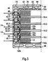
- the Fig. 1 shows a perspective side view of an embodiment of the electric heater with a housing 2, consisting of a lower housing part 4 and an upper housing part 6. Both housing parts 4, 6 are positively connected to each other and take in a heating block 8, which arranged from a plurality of parallel layers to each other heat-generating elements 10 and heat-emitting elements 12 consists.
- the heat-emitting elements 12 are formed as corrugated rib elements of meandering bent sheet metal strip.
- contact tongues 15 are arranged one above the other in the transverse direction.
- the contact tongues pass through slots 16 which are recessed on the housing 2 and which in each case receive a contact tongue and are predominantly formed by the housing lower part 4, but on one end side are completed by the upper housing part 6.
- the housing 2 has two opposite frame openings, of which in Fig. 1 only the frame opening 16 formed by the upper housing part 6 can be seen formed by the lower housing part 4 frame opening is in Fig. 4 and identified by reference numeral 18.
- the frame openings 16, 18 are each interspersed with struts 20 which extend at right angles to the layers of the heating block 8 and connect the opposing longitudinal beams of the lower housing part 4 and upper housing part 8 with each other.
- the Fig. 2 shows details of the heating block 8 and its inclusion in particular in the lower housing part 4 and shows the lower housing part 4 in a plan view with the housing upper part removed.
- the heat-emitting elements 12 are only incompletely shown at the respective end faces of the housing lower part 4. Accordingly, the illustration in Fig. 2 also a view of the frame opening 18 formed by the lower housing part 4 free.
- the exemplary embodiment shown has four heat-generating elements 10, which are each accommodated in the housing lower part 4 in an insulating manner and with a certain mobility transverse to the layers of the layer structure (heating block 8).
- the lower housing part 4 has for this purpose fitting element receptacles 22 which open a receptacle 24, which is formed essentially by the housing lower part 4 and accommodates the heating block 8.
- fitting element receptacles 22a, 22b are provided in the exemplary embodiment shown (cf. Fig. 3 ).
- the heat-generating elements 10 have at their front ends fitting elements 26a, 26b which respectively fit only in the corresponding corresponding fitting element receptacle 22a or 22b.
- the corresponding fitting element receptacles 22 are matched to the fitting elements 26 provided corresponding thereto, that the heat-generating elements 10 are movable by a few tenths of a millimeter transversely to the longitudinal extent of the layers of the heating block 8 in the housing 2.
- the outer fitting elements 26a are designed as a hammer head and engage in correspondingly formed fitting element receptacles 22a.
- the fitting elements 26b associated with these elongated fitting element receptacles 22b are rod-shaped and less wide than the hammer-head-like fitting elements 26a. Due to this particular configuration, the central heat-generating elements 10 do not fit in the outer positions for heat-generating elements 10 of the heating block. In appropriate Way, the outer heat-generating elements can not be arranged in the middle of the heating block, ie insert into the housing 2.
- the heat-generating elements 10 can not be used anywhere in the housing 2, the heat-emitting corrugated fin elements 12 are nonspecific and as lengths of a meandering curved first sheet metal strip as manufactured and cut from this continuous material to length. Each individual heat-emitting element 12 can be used at any position for a heat-emitting element within the heating block 8.
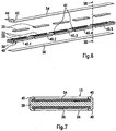
- the fitting elements 26 are integrally formed on a positioning frame 28, which in the 6 and 7 can be seen and explained in more detail below with reference to these figures.
- the positioning frame 28 is made of an insulating material and serves for the positioning of PTC heating elements 30.
- a receptacle 32 in the positioning frame 28 is recessed for each individual PTC heating element 30, which surrounds this PTC heating element and thus defines it.
- sheet metal strips 34, 36 which form electrical conductors for energizing the PTC heating elements 30 and via which the heat generated by the PTC heating elements to the heat-emitting elements 12 is passed by heat transfer. These lie directly on the metal bands 34, 36 at.
- the front ends of the positioning frames 28 are extended beyond a fitting element web 38 beyond the position of the metal bands 34, 36.
- At the outer end of the fitting element webs 38 are the respective fitting elements 26 of the positioning frame 28.
- the vast extent of the position frame 28 in the width direction of the respective metal bands 34, 36 is taken.
- the positioning frame on holding webs 40 which are provided immediately adjacent to the lateral edge of the metal strips 34, 36 and the corresponding metal strips 34, 36 project beyond the top and these overlap on the outside, preferably with the tracks 34, 36 in contact and abut this.
- the holding webs 40 are formed in the embodiment shown in one piece by way of injection molding initially as a right angle to the main extension direction of the position frame 28 outgoing projections.
- the distance of opposing projections is selected so that the sheet metal strip 34 or 36 just fits between these projections.
- the one-piece component thus produced by injection molding is then provided with the essential parts of the heat-generating element 10, i. the PTC heating elements 30 are inserted into the corresponding receptacle 32 and surrounded on both sides by the metal strips 34, 36. Thereafter, the projections are plastically deformed inwardly and so the interconnects 34, 36 formed across.
- a hot forming is used, in which the holding webs 40 forming material locally in the area of the metal strips 34, 36 warms up and thus softened.
- the means used in each case can locally heat the position frame 28, for example by means of hot air or by heat conduction.
- the heating effecting agent is preferably formed by a tool which simultaneously performs the transformation of the retaining webs 40.
- the holding webs 40 are not continuous in the longitudinal direction of the heat-generating element 10, but are provided in sections 40.1 to 40.5. These sections 40.1 to 40.5 leave between them a passage 41 free, which is designed such that in each case a strut 22 in the width direction between the sections 40.1; 40.2; 40.3; 40.4 or 40.5 fits.
- the section formed by the passage 41 in any case, projects inwards in relation to the outer surface of the retaining webs 40 to such an extent that at least half the thickness of the struts 22 fits between the retaining webs 40 and is accommodated there.
- the struts 22 and the positioning frame 28 may also be referred to as the first strut, and the retaining webs 40, which may be referred to as the second strut 43.
- the heat-generating element 10 is formed as a preassembled component and can thus be handled during assembly, without the risk that the conductor tracks 34, 36 or even the inserted in the position frame 28 PTC heating elements 30 are lost. It should be noted, however, that usually the holding webs only fix the metal strips 34, 36 in the position frame, but not with a contact force against the PTC heating elements 30 put, which is sufficient to energize the PTC heating elements 30 during operation safe. This is in any case effected in the embodiment discussed in the context of the present invention by a spring element, which will be described below with reference to the Fig. 8 to 10 will be explained in more detail.
- Fig. 3 and 6 is a metal strip, namely in Fig. 6 shown sheet metal strip 34, bent out of the plane of the heat generating element 10 ago. Accordingly, an offset 42 results between the plane in which the sheet metal strip 34 abuts against the PTC heating elements 30, and a free end 44, which by repeated, but opposite bending extends parallel to the first-mentioned main portion of the sheet metal strip 34. Again Fig. 3 can be seen, this free end 44 is mechanically and electrically connected by a crimp 46 to the associated contact tongue 14.
- upper heat-emitting elements have an outgoing from the upper sheet metal strip 34 offset 42.3 and 42.4.
- the lower heat generating element 10.1 has a downwardly outgoing offset 42.1.
- the metal strips 34, 36 of the heat generating element 10 marked with reference numeral 10.2 are on both sides to form an offset 42.20 or 42.21 arc and each provided with a contact tongue 14. Due to these differences, it is possible to avoid exchanging the positions for the heat-generating elements 10.3 and 10.2 within the housing 2. In the present case, he allows the embodiment that due to the design of contact reeds 48, the two middle heat-generating elements 10.2 and 10.3 can be interchanged. A corresponding interchangeability is also given for the two outer heat-generating elements 10.1 and 10.4.
- the lower housing part 4 can be molded in an injection mold that can be produced cost-effectively, since all areas significant for the housing 4 extend parallel or at right angles to the frame opening 18 of the housing lower part 4.
- the lower housing part 4 initially substantially mutually perpendicular frame surfaces 52a-d, which surround the heating block 8 circumferentially and perpendicular to the plane containing the frame opening 18 includes.
- the corresponding frame surface 52b opens outwardly via four fitting element web receivers 54, whose main walls likewise extend at right angles to the plane containing the frame opening 18.
- a corresponding extension have those functional surfaces of the housing lower part 4, which form the contact tongue receptacle 48 and the here leading slots 15 and 50 substantially and those walls which limit the fitting element receptacle 22 and in Fig. 3 are shown.
- the receptacles 15, 22, 50 and 54 described above are bounded on the side of the lower housing part 4 by a bottom which runs parallel to the plane containing the frame opening 18 of the housing lower part 4.
- This receiving floor is in Fig. 4 designated by reference numeral 56.
- This bottom 56 also forms the inner surface of the struts 22 and edge-side stops 58, 60 for the yet to be explained spring element on the one hand and for the located on the opposite longitudinal side outer heat-emitting element 12 on the other.
- These stops 58 and 60 in turn are parallel to the plane which also contains the frame opening 18.
- a pin guide 70 which is formed with a relatively short length and opens to a window 74, which at the Outside of the housing base 4 is located.
- the pin guide 68 Adjacent to this central pin guide 70, the pin guide 68 is provided, each extending over about 1/3 of the length of the longitudinal bars 64, 66.
- pin guides 70 At the outer end of these pin guides 68 are in turn pin guides 70 with associated windows 74, as described above.
- relatively small pin guides 72 are formed on the end of the longitudinal beams 64, 66 extending from the inner surface of the longitudinal beams 64, 66 to the outer surface of the housing base, which also includes the frame opening 18.
- the functional surfaces forming the pin guides 68, 70, 72 all extend at right angles to the plane containing the frame opening 18. Only the front edges of the corresponding openings 68 to 72 are slightly chamfered or rounded in order to facilitate the insertion of corresponding guide pins 76 to 80 of the upper housing part 6. To facilitate connection of the lower housing part 4 and the upper housing part, the free ends of the walls are further chamfered or rounded, which delimit the spacers 62 and the receptacles 22b, 15, 50, 48 at the end and form the upper ends of the spacers 62.
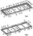
- FIG. 5 shown in perspective housing upper part 6 also has only orthogonal or parallel to the corresponding housing opening 16 aligned functional and boundary surfaces.
- the guide surfaces of the previously mentioned guide pins 76, 78, 80 are provided as functional surfaces, which can be introduced into the corresponding pin guides 68, 70, 72.
- the guide pins 78 are formed as latching pins and form latching webs 82, which are surmounted on the upper side by a thickened head of the latching pin 78, which form a latching surface 86 which extends parallel to the plane which also contains the frame opening 16.
- the latching webs 82 are derived from the top of a cover 88, which is formed as a substantially planar member and the frame opening 16 predetermines and further includes the outer surface of the struts 22.
- the cover 88 is formed frame-shaped as a cover for the lower housing part 4. Accordingly, the guide pin 76 to 80 from the inside of the cover 88 are perpendicular from.
- a bulge 90 is provided for the locking webs 82. In the area of the bulge 90, the edge surface of the cover 88 is retracted inwards, so that the flat planar side surface of the latching web 82 extends parallel to the guide surfaces of the guide pins 76 and 80, but inwardly to the respective outer guide surface of these guide pins 76, 80th lies.
- the the Heating block 8 facing inner surfaces of the corresponding guide pins 78 to 80 are, however, in a plane.
- a further guide pin 92 is provided, which cooperates with a corresponding thereto recessed on the lower housing part 4 further guide recess 94, but does not fit into the fitting element receptacles 22 and the Reeds 48, so that it is ensured that the upper housing part 6 in dismissstimmter and clearly placed on the lower housing part 4 and joined with this.
- the walls surrounding the further pin guide 94 and forming the guide pin 92 also extend at right angles to the plane lying on the frame opening 16 or 18.
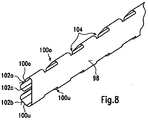
- the Fig. 8 shows a perspective side view of a spring element 96, which rests against the edge of the heating block 8 and is in its installed position at the height of the heating block 8.
- front side of the spring element 96 forms a flat contact surface 98, at which the adjacent, in Fig. 3 uppermost heat-emitting element rests with its lamellae. More precisely, the ends, which are bent over at the ends, lie more meandering lamellae of the corrugated ribbed strip 12 against this contact surface 98.
- the abutment surface 98 is formed by a first flat sheet metal strip on which both sides transverse outgoing leg spring 100 have been formed by punching, which are initially within the plane of the contact surface 98 and after punching by bending in the as in the Fig. 8 . 10 . 11 and 12 recognizable shape have been brought.
- Two spring legs 100o, 100u lie in the width direction, ie transversely to the longitudinal extent of the planar contact surface 98 and thus in the insertion direction of the spring element 96 during assembly above the other.
- Each individual spring limb 100o, 100u forms an inclined sliding surface 102a, 102b, 102c, which in each case enclose an angle of between 35 and 55 °, preferably of approximately 45 °, between itself and the planar contact surface.
- Between the longitudinal direction of the spring element 96 successively provided pairs of spring legs 100 are flat segments 104, in which the spring element 96 is formed as a rectangular flat sheet metal strip.
- spring element 96 has pairs of spring legs 100o, 100u corresponding to the number of spaces between the individual spacers 62 on the longitudinal spar 64 (see. Fig. 4 ). Each pair of spring legs 100o, 100u is in the installed position of the spring element 96 between these spacers 62.
- the flat segment 104 bridges the width of the spacers 62 and connects adjacent spring leg pairs 100o, 100u together.
- the correspondingly produced spring can thus be introduced as a one-piece component into the housing 2, in particular in the housing lower part 4, which simplifies the production of the electrical heating device.
- the wall portions of the frame surface 42c provided between adjacent spacers 62 accordingly form a support surface 106 for the respective pairs of spring legs 100.
- the spring element 96 Due to the vote of the spring element 100, especially the configuration of the flat segments 104 between the pairs of superposed spring legs 100, it is not possible to introduce the spring element 96 in the wrong orientation in the lower housing part 4.
- the spring element 96 can only be moved into its installed position, in which the spring element is accommodated at the level of the heating block 8 in the housing 2, when the flat contact surface 98 is aligned with the heating block.
- the heating block is held by the spacers 62 at a distance from the support surfaces 106, so that the spring element 96 can be applied to these surfaces at any time and without interference from the heating block 8 when inserted into the housing base 4.
- the spring element 96 With a progressive insertion movement of the spring element 96 in the direction of the heating block 8, ie with progressive introduction into the heating block, the spring element 96 is then forced urgently due to the spring force through the lower spring leg 100u in the direction of the heating block 8, so that the layers 10, 12th of the heating block are compressed.
- the flat contact surface 98 then already has such an overlap with the adjacent heat-emitting element 12, that the spring element 96 is sufficiently guided in the direction of insertion between the heating block 8 and the lower housing part 4 with progressive Einbringterrorism.
- the lower spring leg 100u As the introduction progresses, the lower spring leg 100u is finally elastically compressed.
- the housing-side counterforce is formed by an upper edge 108 which is formed between the support surface 106 and the inner surface of the longitudinal beam 64 through the joint of the two surfaces.
- the housing 2 has a further housing element, which cooperates with the spring element 96.
- This further housing element is formed by an edge 110 of the housing top 6, which is formed between the inner surface of the cover 88 and a bottom 112 of the housing top 6, by the abutting edge of an outer edge 113 defining the bottom 112 of the housing top with the inner surface the cover 88.
- the height offset between this bottom 112 and the inner surface of the cover 88 takes into account the fact that the heating block 8 projects beyond the surface formed by the longitudinal bars 64, 66 surface 63, approximately the same length as the spacers 62nd the inner surface 63 of the longitudinal bars 64, 66 projects beyond.
- the edge 110 abuts an inclined sliding surface 102a of the spring element 96, which is formed by the upper spring leg 100o.
- Fig. 10 and 12a it can be seen, is the upper end of the spring element 96 in a substantially pressure-free state at a distance from the bottom 112 of the upper housing part. 6
- the individual layers 10, 12 are introduced into the lower housing part 4 Thereafter, the spring element 96 manually inserted a little way into the housing base, at least so far until the layers of the heating block 8 against each other and the spring element 96 sufficiently deep between the heating block 6 and the frame surface 52c is provided.
- the guide pins 76, 78, 80, 92 in this case engage in the corresponding pin guides 68, 70, 72, 94 a.
- the spring element 96 initially remains essentially free of tension. In this state can already sufficient overlap between the guide pins and the corresponding recesses are achieved, so that the two housing parts 4, 6 can be moved relative to each other only in a linear direction. Thereafter, the joining of the housing parts 4, 6 under application of the spring force.
- the spring legs 100o, 100u are slightly compressed until the bottom 112 of the upper housing part 6 abuts against the upper end of the spring element 96 (see. Fig. 12b ).
- the two edges 108 and 100 have already slid over a certain distance along the inclined sliding surface 102a and 102b.
- the upper spring leg 100o is elastically bent inwards so far that, as the insertion movement progresses, the free end of the leg 100o, which forms a further inclined sliding surface 100c in the center of the spring element 96, can pass the edge 108 reliably. Thereafter, a progressive joining movement between the two housing parts 4, 6 also leads to the entrainment of the spring element 96.
- the spring element 96 has reached its end position when the two housing parts 4, 6 abut each other with their respective surfaces facing each other.
- the spring element 96 is clamped and held in this installation position due to the spring tension between the heating block 8 and the frame surface 52c. If the spring element 96 is displaced by an unintentional force from the outside, in each case the stop 58 or the bottom 112 of the housing upper part 6 prevents the spring element 96 from being forced out of the housing 2.
- the spring element is brought into its installation position by closing the lower housing part and the upper housing part when closing the housing, in which the spring element is at the height of the heating block, i. is arranged in the plane which is also occupied by the heating block. Furthermore, the spring element is placed under spring preload only during insertion, and that only when the two housing parts 4, 6 are guided by positive engagement of the guide pins 76 to 80 in the corresponding pin guides 68, 70, 72 relative to each other.
- the structural design accordingly offers the possibility of stress-free to introduce the components of the heating block in the housing 24 formed by the housing 2. Only then is the spring tension, and in fact adjacent to each other and within limits against each other positioned housing parts 4, 6.
- a spring element can be seen in front, which has a spring leg, which is initially substantially free of tension in the installed position.
- This spring element is introduced stress-free together with the heating block in the receptacle 24.
- the spring element has a spring leg, the spring leg forms a in the direction of the stop 58 outwardly and down obliquely inclined sliding surface forms, and indeed for a pin which cooperates with the spring element and the corresponding spring leg when joining the upper housing part and lower housing part under spring preload sets, so that the spring element is applied in total against the heating block 8 under spring tension.
- the spring element is initially taken free of stress together with the heating block in the lower housing part and remains stationary when generating the spring preload relative to the joining direction.
- the spring element is slightly displaced only in the plane of the heating block and applied to the heating block. Furthermore is the or the spring leg pivoted to produce the elastic bias.
- the particular design of the heat generating elements 10 allows for easier assembly, since the grid assembly formed by the first and second struts 20, 43 is not completely part of the housing, but the second struts are formed with the frame 28 and thus is located where the PTC heating elements 30 come to rest within the heating block 8.
- housing parts can be produced accordingly, which are relatively simple.
- first and second struts 20, 43 form-fitting support against each other and thus stiffen the housing as a whole.
- the heat-emitting element 12 is prepared as a preassembled unit and further ensured by the fitting elements 26 and the associated receptacles 22 that the heat-generating elements 12 can be installed only at predetermined locations within the housing 2, the manufacture of the electric heater, in particular the assembly of the items also be done by less experienced staff.
- the specific embodiment of the embodiment provides an unambiguous assignment of different components of the electric heater. If this clear assignment is not met, the components of the electric heater can not be mounted.
Description
Die vorliegende Erfindung betrifft eine elektrische Heizvorrichtung, mit einem Heizblock, welcher in einem gegenüberliegende Rahmenöffnungen ausbildenden Gehäuse gehalten ist und parallel Lagen von wärmeabgebenden und wärmeerzeugenden Elementen umfasst und mit einer die jeweilige Rahmenöffnung abdeckenden und das Gehäuse versteifenden Gitteranordnung.The present invention relates to an electric heater, comprising a heating block, which is held in a housing opposite the frame openings forming and parallel layers of heat-emitting and heat-generating elements and with a respective frame opening covering and stiffening the housing grid arrangement.
Ein solcher Zuheizer zur Klimatisierung des Innenraums eines Kraftfahrzeuges ist beispielsweise aus der
Es können ein oder mehrere wärmeerzeugende Elemente als Teil des Heizblocks vorgesehen sein. Die von den wärmeerzeugenden Elementen erzeugte Wärme wird über wärmeabgebende Elemente an das zu erwärmende Medium, d.h. die Luft abgegeben. Diese durchströmt das Gehäuse durch die beiden Rahmenöffnungen, die zwischen sich den ebenen Heizblock aufnehmen. Die Rahmenöffnungen liegen dabei üblicherweise parallel zueinander an gegenüberliegenden Seiten eines im Wesentlichen flachen, rahmenförmigen Gehäuses. Im Hinblick auf eine möglichst kostengünstige Herstellung der elektrischen Heizvorrichtung werden die wärmeabgebenden Elemente in der Regel aus mäandrierend gebogenen Blechstreifen gebildet, die Wellrippen ausbilden. Diese Wellrippen liegen ein- oder beidseitig an wärmeabgebenden Elementen an. Dementsprechend umfasst der Heizblock mehrere Lage von wärmeabgebenden und wärmeerzeugenden Elementen, wobei auch im Hinblick auf die Wärmeauskopplung darauf zu achten ist, dass die wärmeabgebenden Elemente gut an den wärmeerzeugenden Elementen anliegen. Auch hierzu können die wärmeabgebenden Elemente mit den wärmeerzeugenden Elementen fest verbunden und/oder durch wenigstens ein in dem Gehäuse aufgenommenes Federelement unter Vorspannung angelegt werden.One or more heat-generating elements may be provided as part of the heating block. The heat generated by the heat-generating elements is discharged through heat-emitting elements to the medium to be heated, ie the air. This flows through the housing through the two frame openings, which receive the flat heating block between them. The frame openings are usually parallel to each other on opposite sides of a substantially flat, frame-shaped housing. With a view to the most cost-effective production of the electric heater, the heat-emitting elements are usually formed of meandering bent metal strips that form corrugated fins. These corrugated ribs rest on one or both sides of heat-emitting elements. Accordingly, the heating block comprises a plurality of layers of heat-emitting and heat-generating elements, wherein care must also be taken with regard to the heat extraction that the heat-emitting elements abut well on the heat-generating elements. Also for this purpose, the heat-emitting elements can be firmly connected to the heat-generating elements and / or applied by at least one received in the housing spring element under bias.
Statt durch eine mäandrierendes Blechband kann das wärmeabgebende Element auch durch ein stranggepresstes Aluminiumprofil gebildet sein, welches Stege ausbildet, die sich im Wesentlichen rechtwinklig zu den Lagen des Schichtaufbaus, umfassend die wärmeabgebenden und die wärmeerzeugenden Elemente erstrecken. In einem solchen Fall kann die Leiterbahn, d.h. die in der Regel ebene Anlagefläche für das PTC-Heizelement durch die Außenfläche eines solchen stranggepressten Aluminiumprofils gebildet werden. Bei beiden Alternativen Wellrippenelement bzw. Strangpressprofil sind die Anlagefläche für die PTC-Heizelemente elektrisch leitend ausgestaltet und elektrisch mit in dem Gehäuse üblicherweise isoliert voneinander gehaltenen Kontakten verbunden. In dem erstgenannten Fall werden die Kontakte in der Regel durch die freiliegenden Enden der Blechbänder gebildet.Instead of a meandering sheet-metal strip, the heat-emitting element can also be formed by an extruded aluminum profile which forms webs which extend substantially perpendicular to the layers of the layer structure comprising the heat-emitting and the heat-generating elements. In such a case, the trace, i. the generally planar contact surface for the PTC heating element are formed by the outer surface of such an extruded aluminum profile. In both alternatives corrugated fin element or extruded profile, the contact surface for the PTC heating elements are designed to be electrically conductive and electrically connected to the housing usually held in isolation from each other held contacts. In the former case, the contacts are usually formed by the exposed ends of the metal strips.
Der geschichtete Heizblock aus parallelen wärmeabgebenden und wärmeerzeugenden Elementen, gegebenenfalls unter Hinzufügung eines oder mehrerer sich parallel hierzu erstreckender Federelemente ist vorzugsweise in einem Gehäuse mit einem U-förmigen Querschnitt gehalten. Bei der Beaufschlagung des Schichtaufbaus mit einer Feder ist der Rahmen so zu dimensionieren, dass die Federkraft dauerhaft auch bei den erhöhten Temperaturen halten kann. Dabei ist zu beachten, dass der isolierende Rahmen heutzutage nicht zuletzt aus ökonomischen Gründen als Spritzgussteil hergestellt wird. Übliche Gehäuse bestehen heutzutage aus einem Gehäuseunterteil und einem Gehäuseoberteil. Das Gehäuseunterteil bildet hierbei eine Aufnahme für die einzelnen Elemente des Heizblocks sowie erforderlichenfalls des Federelementes aus. In diesem Gehäuseunterteil werden die einzelnen Elemente des Heizblocks angeordnet. Danach wird der Heizblock durch Fügen von Gehäuseoberteil und Gehäuseunterteil in dem Gehäuse eingeschlossen. Hierzu können Ränder, die die Rahmenöffnungen umgeben, den Heizblock teilweise überdecken, so dass der Heizblock zwischen den Rahmenöffnungen eingeschlossen und in dem Gehäuse gehalten ist. Die beiden Gehäuseteile werden danach miteinander verbunden, beispielsweise über eine Rastverbindung.The layered heating block of parallel heat-emitting and heat-generating elements, optionally with the addition of one or more parallel thereto extending spring elements is preferably held in a housing having a U-shaped cross-section. When loading the layer structure with a spring, the frame should be dimensioned so that the spring force can hold permanently even at the elevated temperatures. It should be noted that the insulating frame is nowadays produced not least for economic reasons as an injection molded part. Usual housing today consist of a lower housing part and a housing upper part. The lower housing part forms a receptacle for the individual elements of the heating block and, if necessary, the spring element. In this lower housing part, the individual elements of the heating block are arranged. Thereafter, the heating block is enclosed by joining the upper housing part and the lower housing part in the housing. For this purpose, edges surrounding the frame openings may partially cover the heating block, so that the heating block is enclosed between the frame openings and held in the housing. The two housing parts are then connected to each other, for example via a latching connection.
Bei dieser Art der Montage stellt sich das Problem, dass die einzelnen Lagen des Heizblocks an vorbestimmter Stelle in dem Gehäuse angeordnet werden müssen. Da nicht jedem wärmeerzeugenden Element eigene Kontakte zugeordnet sind, müssen bei der Montage auch die elektrischen Verhältnisse innerhalb des Heizblocks berücksichtigt werden. Es besteht aber zur Verminderung der Herstellungskosten auch der Wunsch, die Teile des Heizblocks möglichst standardisiert auszubilden, so dass für verschiedene Lagen des Heizblocks identische Bauteile verwendet werden können.In this type of assembly, the problem arises that the individual layers of the heating block must be arranged at a predetermined location in the housing. Since not each heat generating element own contacts are assigned, the electrical conditions within the heating block must be taken into account during assembly. However, in order to reduce the production costs, there is also the desire to design the parts of the heating block as standardized as possible, so that identical components can be used for different positions of the heating block.
Des Weiteren soll im Hinblick auf eine kostengünstige Herstellung der elektrischen Heizvorrichtung das Gehäuse selbst möglichst einfach hergestellt werden können. Dabei sind jedoch auch die besonderen Anforderungen zu beachten, die der Einbau von einem oder mehreren Federelementen in das Gehäuse in der Praxis stellt, wenn beim Fügen der Gehäuseteile der Heizblock bereits in dem Rahmen unter Vorspannung gesetzt ist, so dass das Fügen gegen diese Vorspannung zu erfolgen hat.Furthermore, with regard to cost-effective production of the electric heater, the housing itself should be as simple as possible. However, the special requirements that the installation of one or more spring elements in the housing in practice, if in the joining of the housing parts of the heating block is already set in the frame under bias, so that the joining against this bias to took place.
Im Hinblick auf die zuvor diskutierten Probleme ist bereits mit der
Dieser vorbekannte Vorschlag führt zu einer gewissen Erleichterung bei der Montage, die jedoch voraussetzt, dass die Elemente des Heizblocks wie auch das Federelement in der richtigen Positionierung in das Gehäuseunterteil eingebracht werden. Des Weiteren hat das bei dieser elektrischen Heizvorrichtung verwirklichte Gehäuse verschiedene Schrägflächen, die für das Verspannen und Einschließen des Federelementes beim Fügen der Gehäuseteile erforderlich sind.This prior art proposal leads to a certain ease of assembly, which, however, requires that the elements of the heating block as well as the spring element are placed in the correct position in the lower housing part. Furthermore, the realized in this electric heater housing has different inclined surfaces, which are required for the bracing and enclosing of the spring element when joining the housing parts.
Der vorliegenden Erfindung liegt das Problem zugrunde, eine elektrische Heizvorrichtung anzugeben, die sich einfacher und damit kostengünstiger herstellen lässt. Die vorliegende Erfindung will ferner ein wärmeerzeugendes Element einer elektrischen Heizvorrichtung angeben, welches sich zum Einbau in die vorerwähnte elektrische Heizvorrichtung eignet. Gemäß einem weiteren nebengeordneten Aspekt der vorliegenden Erfindung will diese ein Gehäuse angeben, welches als Teil der elektrischen Heizvorrichtung nach der vorliegenden Erfindung zum Einsatz kommen kann und welches sich insbesondere eignet, die wämneer zeugenden Elemente, die mit der vorliegenden Erfindung vorgeschlagen werden, aufzunehmen.The present invention is based on the problem of specifying an electric heater which can be produced more simply and thus more cost-effectively. The present invention further seeks to provide a heat generating element of an electric heater which is suitable for installation in the aforementioned electric heater. According to a further independent aspect of the present invention, the invention is intended to specify a housing which can be used as part of the electrical heating device according to the present invention and which is particularly suitable for accommodating the heat generating elements proposed by the present invention.
Zur Lösung des erstgenannten Problems wird mit der vorliegenden Erfindung eine elektrische Heizvorrichtung mit den Merkmalen von Anspruch 1 vorgeschlagen. Diese unterscheidet sich von der gattungsbildenden elektrischen Heizvorrichtung dadurch, dass sich rechtwinklig zu den Lagen erstreckende erste Streben der Gitteranordnung dem Gehäuse zugeordnet und sich parallel zu den Lagen erstreckende zweite Streben durch den Heizblock gebildet sind.To solve the former problem, the present invention proposes an electric heater having the features of claim 1. This differs from the generic electric heater in that at right angles to the layers extending first struts of the grid assembly associated with the housing and extending parallel to the layers extending second struts are formed by the heating block.
In Abkehr von der
Die
Die ersten und zweiten Streben der erfindungsgemäßen elektrischen Heizvorrichtung tragen vorzugsweise jeweils zu einer gewissen Versteifung der Gitteranordnung bei, die die Rahmenöffnungen durchsetzt. Hierzu ist es allerdings nicht erforderlich, dass sich die kreuzenden rechtwinklig zueinander vorgesehenen Streben fest miteinander verbunden sind. Vielmehr reicht ein gewisser Formschluss und/oder eine gewisse Abstützung der ersten und zweiten Streben für eine gewisse Versteifung der Gitteranordnung aus.The first and second struts of the electric heating device according to the invention preferably each contribute to a certain stiffening of the grid arrangement, which passes through the frame openings. For this purpose, however, it is not necessary that the crossing perpendicular to each other provided struts are firmly connected. Rather, a certain form fit and / or a certain support of the first and second struts is sufficient for a certain stiffening of the grid arrangement.
Die zweiten Streben werden durch den Heizblock gebildet, so dass die Position der entsprechenden zweiten Streben in dem Gehäuse erst durch die Einbausituation der Lagen des Heizblocks vorgegeben ist. Dadurch ist es leichter möglich, die zweiten Streben im Bereich der wärmeerzeugenden Elemente vorzusehen, um beispielsweise die Leiterbahnen unterschiedlicher Polarität stirnseitig abzudecken. Entgegen dem zuvor dargestellten Stand der Technik besteht nicht mehr das Problem einer engen toleranzmäßigen Abstimmung zwischen der geometrischen Ausgestaltung des Gehäuses einerseits und den hierin bisweilen beweglich, zumindest aber mit gewissem Spiel gehaltenen Lagen des Heizblocks andererseits.The second struts are formed by the heating block, so that the position of the corresponding second struts in the housing is determined only by the installation situation of the layers of the heating block. This makes it easier to provide the second struts in the region of the heat-generating elements, for example, to cover the conductor tracks of different polarity frontally. Contrary to the prior art described above, there is no longer the problem of close tolerance matching between the geometric configuration of the housing on the one hand and the layers of the heating block, which are sometimes movable, but at least held with some play.
Im Hinblick darauf wird mit einer bevorzugten Weiterbildung der vorliegenden Erfindung vorgeschlagen, die zweiten Streben in Abschnitten zwischen den ersten Streben vorzusehen, und zwar derart, dass die ersten Streben jeweils formschlüssig zwischen zwei Abschnitten der ersten Streben fixiert sind, was bedeutet, dass die ersten Streben im Wesentlichen rechtwinklig zu ihrer Erstreckung, d. h. parallel zu der Längserstreckung der zweiten Streben nur geringfügig oder nicht beweglich sind und dementsprechend formschlüssig zwischen den jeweiligen Abschnitten gehalten sind.In view of this, it is proposed with a preferred development of the present invention to provide the second struts in sections between the first struts, in such a way that the first struts are each positively fixed between two sections of the first struts, which means that the first struts substantially perpendicular to its extent, d. H. parallel to the longitudinal extent of the second struts are only slightly or not movable and are therefore held in a form-fitting manner between the respective sections.
Bei der zuvor erwähnten Weiterbildung können die zweiten Streben in auf die Abmessung der zweiten Streben angepasste Ausnehmungen der ersten Streben eingreifen und somit eine Formschlussverbindung hergestellt sein, welche die beiden Streben im Wesentlichen unbeweglich zueinander fixiert. Es hat sich jedoch für die Versteifung und insbesondere mit Rücksicht auf etwaige Fertigungstoleranzen als vorteilhaft erwiesen, die zweiten Streben in Längsrichtung der ersten Streben gegenüber diesen beweglich anzuordnen. Gemeint ist hiermit insbesondere eine geringfügig bewegliche Lagerung der beiden Streben relativ zueinander, die den Ausgleich von Fertigungstoleranzen erlaubt bzw. ein gewisses Nachgeben der einzelnen Lagen des Heizblocks beispielsweise zum Ausgleich von Wärmedehnungen und/oder als Reaktion auf eine von außen auf den Heizblock wirkende Spannkraft einer oder mehrerer in das Gehäuse eingebauter Federn.In the aforementioned refinement, the second struts can engage in recesses of the first struts adapted to the dimension of the second struts and thus produce a form-locking connection which fixes the two struts substantially immovably to one another. However, it has proved to be advantageous for the stiffening and in particular with regard to possible manufacturing tolerances to arrange the second struts in the longitudinal direction of the first struts with respect to these movable. This means in particular a slightly movable mounting of the two struts relative to each other, which allows the compensation of manufacturing tolerances or a certain yielding of the individual layers of the heating block, for example, to compensate for thermal expansion and / or in response to an externally acting on the heating block clamping force or more springs built into the housing.
Die zweiten Streben können als abschirmende Bauteile zwischen den oder als Bestandteil der wärmeabgebenden oder wärmeerzeugenden Elemente ausgebildet sein. Besonders zuverlässig ist eine Ausgestaltung, bei der die zweiten Streben unmittelbar durch Teile des wärmeerzeugenden Elementes ausgebildet werden. Es hat sich als vorteilhaft erwiesen, die zweiten Streben durch Positionsrahmen aus einem isolierenden Material auszubilden, welcher nebeneinander vorgesehene Aufnahmen für jeweils wenigstens ein PTC-Heizelement ausbildet und die zwischen Leiterbahnen angeordnet sind, an denen die PTC-Heizelemente elektrisch leitend anliegen. Mit dieser bevorzugten Weiterbildung werden die Streben als einheitliches Element mit den wärmeerzeugenden Elementen ausgeformt, so dass eine richtige Positionierung der Streben auf einfache Weise gewährleistet werden kann.The second struts can be designed as shielding components between or as part of the heat-emitting or heat-generating elements. Particularly reliable is an embodiment in which the second struts are formed directly by parts of the heat-generating element. It has proven to be advantageous to form the second struts by positioning frame made of an insulating material, which forms side by side receptacles for each forming at least one PTC heating element and which are arranged between interconnects on which abut the PTC heating elements electrically conductive. With this preferred development, the struts are formed as a unitary element with the heat-generating elements, so that a correct positioning of the struts can be ensured in a simple manner.
Im Hinblick auf eine gute Abschirmung der elektrischen Leiterbahnen und mit Rücksicht auf eine gewünschte mechanische Wechselwirkung und Abstützung der beiden Streben wird gemäß einer bevorzugten Weiterbildung der vorliegenden Erfindung vorgeschlagen, die Leiterbahnen beidseitig auf den PTC-Elementen aufzulegen, d. h. die Leiterbahnen als Elemente vorzusehen, die zunächst separat und losgelöst von den PTC-Elementen sind, und die Abschnitte der zweiten Streben so auszuformen, dass diese die Leiterbahnen außenseitig übergreifen und damit an dem Positionsrahmen unverlierbar sichern. Mit dieser bevorzugten Ausgestaltung wird eine vormontierte Baugruppe geschaffen, die sich bei der Herstellung der elektrischen Heizvorrichtung als einheitliches Element handhaben und einbauen lässt.With regard to a good shielding of the electrical conductor tracks and with regard to a desired mechanical interaction and support of the two struts, it is proposed according to a preferred development of the present invention to apply the conductor tracks on both sides of the PTC elements, ie to provide the conductor tracks as elements which initially separate and detached from the PTC elements, and form the sections of the second struts so that they overlap the tracks outside and thus secure captive on the position frame. With this preferred embodiment, a pre-assembled assembly is created, which can be handled and installed as a unitary element in the manufacture of the electric heater.
Dabei können die konstruktiven Anforderungen, die an die Abschnitte bzw. Streben insofern zur Fixierung der Leiterbahnen gestellt werden, relativ gering sein, wenn die Leiterbahnen im eingebauten Zustand durch eine den Heizblock unter Federvorspannung in dem Gehäuse haltende Federeinrichtung gegen die PTC-Heizelemente angelegt wird, wie dies beispielsweise aus der
Zur materialschonenden Herstellung der zweiten Streben wird gemäß einer weiteren bevorzugten Ausgestaltung der vorliegenden Erfindung vorgeschlagen, die Ober- und Unterseite der wärmeerzeugenden Elemente zwischen den Abschnitten der zweiten Streben durch die Leiterbahnen auszubilden. Die Leiterbahnen liegen dementsprechend zwischen den Abschnitten der zweiten Streben frei und sind erst nach Einbau in das Gehäuse von den ersten Streben abgeschirmt und damit abgedeckt. Die Weiterbildung ermöglicht des Weiteren einen relativ flachen Aufbau der elektrischen Heizvorrichtung bei Verwendung relativ vieler standardisierter Bauteile, wie beispielsweise Blechbänder als Leiterbahnen.For material-friendly production of the second struts, it is proposed according to a further preferred embodiment of the present invention to form the top and bottom of the heat-generating elements between the sections of the second struts through the conductor tracks. The tracks are accordingly free between the sections of the second struts and are shielded only after installation in the housing of the first struts and thus covered. The development further allows a relatively flat structure of the electric heater using relatively many standardized components, such as metal strips as interconnects.
Zur Lösung des nebengeordneten Aspekts der vorliegenden Erfindung gibt diese ein wärmeabgebendes Element einer elektrischen Heizvorrichtung der eingangs genannten Art an, welches einen Positionsrahmen aus einem isolierenden Material umfasst, der nebeneinander liegende Aufnahmen für jeweils ein PTC-Heizelement ausbildet, die zwischen Leiterbahnen angeordnet sind, an denen die PTC-Heizelemente elektrisch leitend anliegen. Dieses aus der
Bevorzugte Weiterbildungen des erfindungsgemäßen wärmeerzeugenden Elementes sind in den Ansprüchen 9 bis 13 angegeben.Preferred developments of the heat-generating element according to the invention are specified in claims 9 to 13.
Mit der vorliegenden Erfindung wird ferner ein Gehäuse einer Heizvorrichtung angegeben, in das das wärmeerzeugende Element nach der vorliegenden Erfindung zur Herstellung der elektrischen Heizvorrichtung nach der vorliegenden Erfindung eingebaut werden kann. Dieses Gehäuse zeichnet sich dadurch aus, dass die Rahmenöffnungen von Streben durchsetzt sind, die sich lediglich rechtwinklig zu den Lagen von wärmeabgebenden und wärmeerzeugenden Elementen erstrecken. Vor dem Zusammenbau des Gehäuses ergibt sich diese Besonderheit der Streben aus einem Vergleich zwischen der Ausgestaltung der Aufnahmeöffnungen für Teile des Heizblocks, die an den stimseitigen Enden der Lagen des Heizblocks vorgesehen sein können, oder aber der Schlitze oder anderer Durchführungen für elektrische Leiterbahnen des Heizblocks, die in der Regel ebenfalls stirnseitig aus dem Heizblock heraus und dort in das Gehäuse hinein geführt sind mit der Ausrichtung der Streben des Gehäuses..The present invention further provides a housing of a heater into which the heat-generating element according to the present invention for manufacturing the electric heater of the present invention can be installed. This housing is characterized in that the frame openings are penetrated by struts which extend only at right angles to the layers of heat-emitting and heat-generating elements. Prior to assembly of the housing, this peculiarity of the struts results from a comparison between the configuration of the receiving openings for parts of the heating block, which may be provided at the front ends of the layers of the heating block, or the slots or other bushings for electrical conductors of the heating block, which are also usually the front side out of the heating block and out there into the housing with the orientation of the struts of the housing ..
Eine bevorzugte Weiterbildung des erfindungsgemäßen Gehäuses ist in Anspruch 15 angegeben.A preferred embodiment of the housing according to the invention is specified in
Weitere Einzelheiten und Vorteile ergeben sich aus der nachfolgenden Beschreibung eines Ausführungsbeispiels in Verbindung mit der Zeichnung. In dieser zeigen:
- Fig. 1
- eine perspektivische Seitenansicht eines Ausführungsbeispiels der elektrischen Heizvorrtichtung:
- Fig. 2
- eine Seitenansicht auf ein Gehäuseunterteil mit darin eingebautem Heizblock des in
Fig. 1 gezeigten Ausführungsbeispiels; - Fig. 3
- einen vergrößerten Ausschnitt der Darstellung gemäß
Fig. 2 ; - Fig. 4
- eine perspektivische Seitenansicht des in den
Fig. 1 bis 3 gezeigten Ausführungsbeispiels; - Fig. 5
- eine perspektivische Seitenansicht des Gehäuseoberteils der elektrischen Heizvorrichtung nach
Fig. 1 ; - Fig. 6
- eine perspektivische Explosionsdarstellung eines wärmeerzeugenden Elementes der elektrischen Heizvorrichtung nach
Fig. 1 ; - Fig. 7
- eine Schnittdarstellung entlang der Linie VII-VII gemäß der Darstellung in
Fig. 6 eines montierten wärmeerzeugenden Elementes; - Fig. 8
- eine perspektivische Seitenansicht eines Federelementes zur Verspannung des Heizblocks des in den
Fig. 1 bis 7 verdeutlichten Ausführungsbeispiels; - Fig. 9
- eine Seitenansicht eines Endes des Beispiels gemäß
Fig. 1 vor dem Fügen der Gehäuseteile; - Fig. 10
- eine Schnittansicht entlang der Linie X-X gemäß der Darstellung in
Fig. 9 ; - Fig. 11
- eine vergrößerte Detailansicht des Ausschnitts A in
Fig. 10 und - Fig. 12a
- bis e vergrößerte Detailansichten ähnlich zu der Ansicht gemäß
Figur 11 in verschiedenen Stadien beim Fügen der Gehäuseteile.
- Fig. 1
- a perspective side view of an embodiment of the electrical Heizvorrtichtung:
- Fig. 2
- a side view of a housing base with built-in heating block of in
Fig. 1 shown embodiment; - Fig. 3
- an enlarged section of the illustration according to
Fig. 2 ; - Fig. 4
- a side perspective view of the in the
Fig. 1 to 3 shown embodiment; - Fig. 5
- a perspective side view of the housing top of the electric heating device according to
Fig. 1 ; - Fig. 6
- an exploded perspective view of a heat generating element of the electric heating device according to
Fig. 1 ; - Fig. 7
- a sectional view taken along the line VII-VII as shown in FIG
Fig. 6 a mounted heat generating element; - Fig. 8
- a perspective side view of a spring element for clamping the heating block of the in the
Fig. 1 to 7 illustrated embodiment; - Fig. 9
- a side view of an end of the example according to
Fig. 1 before joining the housing parts; - Fig. 10
- a sectional view taken along line XX as shown in FIG
Fig. 9 ; - Fig. 11
- an enlarged detail view of the section A in
Fig. 10 and - Fig. 12a
- to e enlarged detail views similar to the view according to
FIG. 11 in various stages when joining the housing parts.
Die
An einer Stirnseite des Gehäuses 2 wird dieses von fünf in Querrichtung übereinander angeordneten Kontaktzungen 15 überragt Die Kontaktzungen treten durch an dem Gehäuse 2 ausgesparte Schlitze 16 hindurch, die jeweils für sich eine Kontaktzunge aufnehmen und überwiegend durch das Gehäuseunterteil 4 gebildet sind, jedoch an einer Stirnseite durch das Gehäuseoberteil 6 komplettiert sind.At one end face of the housing 2, this is surmounted by five
Das Gehäuse 2 weist zwei gegenüberliegende Rahmenöffnungen auf, von denen in
Die
Wie zu erkennen, weist das gezeigte Ausführungsbeispiel vier wärmeerzeugende Elemente 10 auf, die jeweils stirnseitig isolierend und mit gewisser Beweglichkeit quer zu den Lagen des Schichtaufbaus (Heizblocks 8) in dem Gehäuseunterteil 4 aufgenommen sind. Das Gehäuseunterteil 4 weist hierzu Passelementaufnahmen 22 auf, die sich einer Aufnahme 24, die im Wesentlichen durch das Gehäuseunterteil 4 gebildet ist und den Heizblock 8 aufnimmt, öffnen. An jeder Stirnseite des Gehäuseunterteils 4 sind bei dem gezeigten Ausführungsbeispiel zwei unterschiedliche Arten von Passelementaufnahmen 22a, 22b vorgesehen (vgl. auch
Während die wärmeerzeugenden Elementen 10 nicht an jeder beliebigen Stelle im Gehäuse 2 eingesetzt werden können, sind die wärmeabgebenden Wellrippenelemente 12 unspezifisch und als Längenabschnitte eines mäandrierend gebogenen zunächst Blechstreifens als gefertigt und von diesem Endlosmaterial auf Länge geschnitten. Jedes einzelne wärmeabgebende Element 12 kann an beliebiger Position für ein wärmeabgebendes Element innerhalb des Heizblocks 8 eingesetzt werden.While the heat-generating
Die Passelemente 26 sind einstückig an einem Positionsrahmen 28 angeformt, der in den
Die stimseitigen Enden der Positionsrahmen 28 sind über einen Passelementsteg 38 über die Lage der Blechbänder 34, 36 hinaus verlängert. Am äußeren Ende der Passelementstege 38 befinden sich die jeweiligen Passelemente 26 des Positionsrahmens 28. Wie die Querschnittsansicht entlang der in
Das auf diese Weise mittels Spritzgießen hergestellte einteilige Bauteil wird danach mit den wesentlichen Teilen des wärmeerzeugenden Elementes 10 versehen, d.h. die PTC-Heizelemente 30 werden in die korrespondierenden Aufnahme 32 eingelegt und beidseitig von den Blechbändern 34, 36 umgeben. Danach werden die Vorsprünge plastisch nach innen verformt und so die Leiterbahnen 34, 36 übergreifend ausgebildet. Hierbei kommt üblicherweise ein Warmumformen zum Einsatz, bei dem das die Haltestege 40 bildende Material lokal im Bereich der Blechbänder 34, 36 aufwärmt und somit erweicht wird. Das jeweils zum Einsatz kommende Mittel kann beispielsweise mittels Heißluft oder durch Wärmeleitung den Positionsrahmen 28 lokal erwärmen. Im Falle der Erwärmung durch Wärmeleitung wird das die Erwärmung bewirkende Mittel vorzugsweise durch ein Werkzeug gebildet, welches gleichzeitig die Umformung der Haltestege 40 vornimmt.The one-piece component thus produced by injection molding is then provided with the essential parts of the heat-generating
Die Haltestege 40 sind in Längsrichtung des wärmeerzeugenden Elementes 10 nicht durchgängig ausgebildet, sondern sind in Abschnitten 40.1 bis 40.5 vorgesehen. Diese Abschnitte 40.1 bis 40.5 lassen zwischen sich einen Durchgang 41 frei, der derart ausgestaltet ist, dass jeweils eine Strebe 22 in Breitenrichtung zwischen die Abschnitte 40.1; 40.2; 40.3; 40.4 bzw. 40.5 passt. Der durch den Durchgang 41 gebildete Abschnitt verspringt gegenüber der Außenfläche der Haltestege 40 jedenfalls so weit nach innen, dass zumindest die halbe Dicke der Streben 22 zwischen die Haltestege 40 passt und dort aufgenommen ist.The holding
Allerdings fehlt es an einem formschlüssigen Eingriff zwischen den Streben 22 und den Positionsrahmen 28 in einer Richtung quer zu den Lagen des Heizblocks 8, so dass eine Beweglichkeit quer zu den Lagen des Heizblocks 8 gegeben ist zwischen den Streben 22 der Gehäuseteile 4, 6, die auch als erste Strebe bezeichnet werden können, und den Haltestegen 40, die als zweite Strebe 43 bezeichnet werden können.However, there is a lack of a positive engagement between the
Das wärmeerzeugende Element 10 ist als vormontiertes Bauteil ausgebildet und kann somit bei der Montage gehandhabt werden, ohne dass die Gefahr besteht, dass die Leiterbahnen 34, 36 oder gar die in den Positionsrahmen 28 eingelegten PTC-Heizelemente 30 verloren gehen. Es sei jedoch darauf hingewiesen, dass üblicherweise die Haltestege lediglich die Blechbänder 34, 36 in dem Positionsrahmen fixieren, diese aber nicht mit einer Anpresskraft gegen die PTC-Heizelemente 30 legen, welche ausreicht, die PTC-Heizelemente 30 sicher beim Betrieb zu bestromen. Dies wird jedenfalls bei der im Rahmen der vorliegenden Erfindung diskutierten Ausgestaltung durch ein Federelement bewirkt, welches nachfolgend noch unter Bezugnahme auf die
Zunächst soll aber weiter auf diejenigen Merkmale eingegangen, die dafür Sorge tragen, dass Teile des Heizblocks 8 nicht an beliebiger Stelle innerhalb des Gehäuses 2 eingebaut werden kann.First, however, will continue to discuss those features that ensure that parts of the
Wie insbesondere den
Die in
Die zuvor bereits unter Bezugnahme auf
Das Gehäuseunterteil 4 kann in einer kostengünstig herzustellenden Spritzgießform abgeformt werden, da sämtliche, für das Gehäuse 4 bedeutsame Flächen sich parallel oder rechtwinklig zu der Rahmenöffnung 18 des Gehäuseunterteils 4 erstrecken.The lower housing part 4 can be molded in an injection mold that can be produced cost-effectively, since all areas significant for the housing 4 extend parallel or at right angles to the frame opening 18 of the housing lower part 4.
So hat das Gehäuseunterteil 4 zunächst im Wesentlichen rechtwinklig zueinander verlaufende Rahmenflächen 52a-d, die den Heizblock 8 umfänglich umgeben und rechtwinklig zu der Ebene verlaufen, die die Rahmenöffnung 18 beinhaltet. An der Stirnseite, an der die Kontaktzungen 14 aus dem Gehäuseunterteil 4 herausgeführt sind, öffnet sich die korrespondierende Rahmenfläche 52b über vier Passelementstegaufnahmen 54 nach außen, deren Hauptwandungen sich gleichfalls rechtwinklig zu der Ebene erstrecken, die die Rahmenöffnung 18 enthält. Eine entsprechende Erstreckung haben diejenigen Funktionsflächen des Gehäuseunterteils 4, welche die Kontaktzungenaufnahme 48 sowie die hierhin führenden Schlitze 15 bzw. 50 im Wesentlichen ausbilden sowie diejenigen Wände, die die Passelementaufnahme 22 begrenzen und in
Parallel zu dieser Ebene verläuft die innere Oberfläche des Gehäuseunterteils 4, die stirnseitig von den stimseitigen Enden der Wandungen gebildet wird, die die Passelementaufnahmen 22 bzw. die Kontaktzungenaufnahmen 48 ausbilden. An einer Längsseite wird dieser obere Rand durch Abstandshalter 62 gebildet, die die Rahmenfläche 52c zu der Aufnahme 24 hin überragen und auf deren Funktion bei der Beschreibung des Federelementes nachfolgend noch eingegangen wird. Unterhalb dieser oberen Ebene der inneren Oberfläche des Gehäuseunterteils 4 befinden sich inneren Oberflächen 63 der beiden Längsholme 64, 66 des Gehäuseunterteils 4, die allerdings die randseitigen Anschläge 58, 60 so weit überragen, dass der Heizblock 8 nahezu vollständig, d.h. mit mehr als 70 % seiner höhenmäßigen Erstreckung in dem Gehäuseunterteil 4 umfänglich gefasst ist. Die Längsholme 64, 66 sind von Zapfenführungen 68, 70, 72 durchsetzt, die sich rechtwinklig zu der Ebene erstrecken, die die Rahmenöffnung 18 enthält. Die Zapfenführungen 68, 70, 72 durchsetzen abschnittsweise im Wesentlichen die gesamte Längserstreckung der Längsholme 44, 66.Parallel to this plane runs the inner surface of the lower housing part 4, which is formed frontally of the front ends of the walls, which form the
In der Mitte der jeweiligen Längsholme 64, 66 befindet sich eine Zapfenführung 70, die mit relativ geringer Länge ausgebildet ist und sich zu einem Fenster 74 öffnet, welches an der Außenseite des Gehäuseunterteils 4 liegt. Benachbart zu dieser mittleren Zapfenführung 70 ist die Zapfenführung 68 vorgesehen, die sich jeweils über etwa 1/3 der Länge der Längsholme 64, 66 erstrecken. An dem äußeren Ende dieser Zapfenführungen 68 befinden sich wiederum Zapfenführungen 70 mit zugeordneten Fenstern 74, wie vorstehend beschrieben. An den stimseitigen Enden der Längsholme 64, 66 sind wiederum relativ kleine Zapfenführungen 72 ausgebildet, die sich von der inneren Oberfläche der Längsholme 64, 66 bis zu der Außenfläche des Gehäuseunterteils erstrecken, die auch die Rahmenöffnung 18 enthält.In the middle of the respective
Die die Zapfenführungen 68, 70, 72 bildenden bzw. begrenzenden Funktionsflächen erstrecken sich sämtlich rechtwinklig zu der Ebene, die die Rahmenöffnung 18 enthält. Lediglich die stirnseitigen Ränder der entsprechenden Öffnungen 68 bis 72 sind leicht angefast bzw. abgerundet, um das Einführen von korrespondierenden Führungszapfen 76 bis 80 des Gehäuseoberteils 6 zu erleichtern. Zum leichteren Verbinden von Gehäuseunterteil 4 und Gehäuseoberteil sind des Weiteren auch die freien Enden der Wandungen angefast bzw. abgerundet, die die Abstandshalter 62 sowie die Aufnahmen 22b, 15, 50, 48 endseitig begrenzen und die oberen Enden der Abstandshalter 62 bilden.The functional surfaces forming the pin guides 68, 70, 72 all extend at right angles to the plane containing the
Das in
An einer Stirnseite des Gehäuseoberteils 6 sind an der Innenwand der Abdeckung 88 fünf Aussparungen, korrespondierend zu den fünf Kontaktzungenaufnahmen 48 ausgebildet, die einen Teil der Schlitze 15 bilden und auch einen oberen Randbereich, der Kontaktzungen 14 nach Montage des Heizblocks in dem geschlossenen Gehäuse umfassen. Auf der gegenüberliegenden Stirnseite ist ein weiterer Führungszapfen 92 vorgesehen, welcher mit einer korrespondierend hierzu an dem Gehäuseunterteil 4 ausgesparten weiteren Führungsausnehmung 94 zusammenwirkt, jedoch nicht in die Passelementaufnahmen 22 bzw. die Kontaktzungenaufnahmen 48 passt, so dass sichergestellt ist, dass das Gehäuseoberteil 6 in vorbestimmter und eindeutiger Weise auf das Gehäuseunterteil 4 aufgesetzt und mit diesem gefügt wird. Auch die die weitere Zapfenführung 94 umgebenden sowie den Führungszapfen 92 bildenden Wandungen erstrecken sich rechtwinklig zu der Ebene, die auf Rahmenöffnung 16 bzw. 18 liegt.On one end side of the
Die
Das in
Bei einer fortschreitenden Einführbewegung des Federelementes 96 in Richtung auf den Heizblock 8, d. h. bei fortschreitendem Einbringen in den Heizblock wird das Federelement 96 dann zwangsläufig aufgrund der Federkraft durch den unteren Federschenkel 100u in Richtung auf den Heizblock 8 gedrängt, so dass die Lagen 10, 12 des Heizblocks komprimiert werden. Die ebene Anlagefläche 98 weist dann bereits eine solche Überdeckung mit dem benachbarten wärmeabgebenden Element 12 auf, dass bei fortschreitender Einbringbewegung das Federelement 96 hinreichend in Einbringrichtung zwischen dem Heizblock 8 und dem Gehäuseunterteil 4 geführt wird. Bei weiter fortschreitendem Einbringen wird schließlich der untere Federschenkel 100u elastisch komprimiert. Die gehäuseseitige Gegenkraft wird hierbei durch eine obere Kante 108 gebildet, die zwischen der Stützfläche 106 und der inneren Oberfläche des Längsholmes 64 durch die Stoßstelle der beiden Flächen ausgebildet wird. Diese Kante 108 drängt beim Einbringen des Federelementes 96 zunächst den unteren Federschenkel 100u nach innen. Bei fortlaufender Einbringbewegung wird schließlich der obere Federschenkel 100o durch Zusammenwirken des nach innen abgeschrägt umbogenen freien Endes des entsprechenden Federschenkels 100o nach innen gedrängt.With a progressive insertion movement of the
Wie den
Zur Beschreibung der Montage wird im Folgenden auf die
Diese anfängliche Einbringbewegung, bei welcher das Federelement 96 im Wesentlichen keine Federvorspannung in den Heizblock 8 einbringt, wird das Federelement 96 über dem Heizblock 8 zugewandten stimseitigen Flächen der Abstandshalter 62 geführt, die mit den flachen Segmenten 104 des Federelementes 96 zusammenwirkt. Aufgrund der Anlage von Federelement 96 und Abstandshaltern 62 ist das Federelement mit seiner ebenen Anlagefläche 98 parallel zu den Lagen 4, 6 des Heizblocks ausgerichtet. Nach diesem ersten Montageschritt überragt das Federelement 96 die von dem Heizblock 8 eingenommene Ebene um einen Längenabschnitt, der in
Zunächst werden die Federschenkel 100o, 100u geringfügig komprimiert, bis der Boden 112 des Gehäuseoberteils 6 gegen das obere Ende des Federelementes 96 anstößt (vgl.
Kurz bevor die beiden Gehäuseteile 4, 6 aneinander liegen, werden die in den Führungskanälen unter leichter elastischer Biegung der Raststege 82 in den Zapfenführungen 70 geführten Köpfe 84 nach außen gedrängt, so dass sich deren Rastfläche 96 gegen eine Rastgegenfläche 114 anlegen bzw. diese mit leichtem Spiel überragen, so dass die beiden Gehäuseteile 4, 6 unverlierbar gegeneinander fixiert sind.Shortly before the two
Wie die obige Beschreibung verdeutlicht, wird bei der Herstellung der elektrischen Heizvorrichtung nach dem diskutierten Ausführungsbeispiel das Federelement beim Schließen des Gehäuses durch Fügen von Gehäuseunterteil und Gehäuseoberteil in seine Einbaulage verbracht, in der sich das Federelement auf Höhe des Heizblocks befindet, d.h. in derjenigen Ebene angeordnet ist, die auch von dem Heizblock eingenommen wird. Des Weiteren wird das Federelement erst beim Einbringen unter Federvorspannung gesetzt, und zwar erst dann, wenn die beiden Gehäuseteile 4, 6 durch formschlüssigen Eingriff der Führungszapfen 76 bis 80 in die korrespondierenden Zapfenführungen 68, 70, 72 relativ zueinander geführt sind. Die konstruktive Ausgestaltung bietet dementsprechend die Möglichkeit, die Bauteile des Heizblocks spannungsfrei in die durch das Gehäuse 2 gebildete Aufnahme 24 einzubringen. Erst danach erfolgt die Federverspannung, und zwar bereits bei aneinander anliegenden und in Grenzen gegeneinander positionierten Gehäuseteilen 4, 6. Sollte es danach aufgrund der erzeugten Federvorspannung beim Fügen der Federelemente 4, 6 zu einer Verschiebung der Elemente des Heizblocks 8 oder gar zu einem Herausdringen der Elemente des Heizblocks 8 aus der Aufnahme 24 kommen, werden diese Teile durch die den Heizblock 8 in dem Gehäuse 2 einschließenden Teile der Gehäuseteile 4, 6 gehalten und in die gewünschte Position beim Fügen der Gehäuseteile 4, 6 zurückgedrängt.As the above description makes clear, in the manufacture of the electric heating device according to the discussed embodiment, the spring element is brought into its installation position by closing the lower housing part and the upper housing part when closing the housing, in which the spring element is at the height of the heating block, i. is arranged in the plane which is also occupied by the heating block. Furthermore, the spring element is placed under spring preload only during insertion, and that only when the two
Hinsichtlich der konstruktiven Ausgestaltung ist die vorliegende Erfindung nicht auf das beschriebene Ausführungsbeispiel beschränkt. So kann beispielsweise ein Federelement vor gesehen sein, welches einen Federschenkel aufweist, der in der Einbaulage zunächst im Wesentlichen spannungsfrei ist. Dieses Federelement wird spannungsfrei zusammen mit dem Heizblock in die Aufnahme 24 eingebracht. Das Federelement weist einen Federschenkel auf, der Federschenkel bildet eine in Richtung auf den Anschlag 58 nach außen und unten schräg geneigte Gleitfläche ausbildet, aus und zwar für einen Zapfen, der mit dem Federelement zusammenwirkt und den entsprechenden Federschenkel beim Fügen von Gehäuseoberteil und Gehäuseunterteil unter Federvorspannung setzt, so dass das Federelement insgesamt gegen den Heizblock 8 unter Federvorspannung angelegt wird. Bei dieser Ausgestaltung wird das Federelement zunächst spannungsfrei zusammen mit dem Heizblock in dem Gehäuseunterteil aufgenommen und bleibt aber beim Erzeugen der Federvorspannung ortsfest relativ zu der Fügerichtung. Das Federelement wird lediglich in der Ebene des Heizblocks geringfügig verschoben und an den Heizblock angelegt. Des Weiteren wird der bzw. die Federschenkel zur Erzeugung der elastischen Vorspannung verschwenkt.With regard to the structural design, the present invention is not limited to the described embodiment. For example, a spring element can be seen in front, which has a spring leg, which is initially substantially free of tension in the installed position. This spring element is introduced stress-free together with the heating block in the
Die besondere Ausgestaltung der wärmeerzeugenden Elemente 10 ermöglicht eine einfachere Montage, da die durch die ersten und zweiten Streben 20, 43 gebildete Gitteranordnung nicht vollständig Teil des Gehäuses ist, sondern die zweiten Streben mit den Positionsrahmen 28 ausgebildet werden und sich somit zuverlässig dort befindet, wo die PTC-Heizelemente 30 innerhalb des Heizblocks 8 zum Liegen kommen. Gegenüber dem vorbekannten Stand der Technik, bei dem die Gitteranordnung allein durch die Gehäuseteile ausgebildet werden, können dementsprechend Gehäuseteile hergestellt werden, die verhältnismäßig einfach ausgebildet sind. Des Weiteren kann mit höheren Toleranzen gearbeitet werden, da keine einteilig mit dem Gehäuse verbundenen Streben existieren, die sich parallel zu den Lagen des Heizblocks 8 erstrecken und exakt auf Position der wärmeerzeugenden Elemente 10 vorgesehen sein müssen. Durch die Dimensionierung der Streben 20 und des Durchgangs 41 und insbesondere das Einfügen der Streben 20 zwischen zwei Abschnitte der Haltestege 40 besteht indes die Möglichkeit, die ersten und zweiten Streben 20, 43 formschlüssig gegeneinander abzustützen und somit das Gehäuse insgesamt zu versteifen.The particular design of the
Da das wärmeabgebende Element 12 als vormontierte Baueinheit vorbereitet wird und des Weiteren durch die Passelemente 26 und die zugehörigen Aufnahmen 22 sichergestellt ist, dass die wärmeerzeugenden Elemente 12 lediglich an vorbestimmten Stellen innerhalb des Gehäuses 2 eingebaut werden können, kann die Fertigung der elektrischen Heizvorrichtung, insbesondere die Montage der Einzelteile auch durch wenig geübtes Personal erfolgen.Since the heat-emitting
Die konkrete Ausgestaltung des Ausführungsbeispiels gibt eine eindeutige Zuordnung von verschiedenen Bauteilen der elektrischen Heizvorrichtung vor. Wird diese eindeutige Zuordnung nicht eingehalten, lassen sich die Bauteile der elektrischen Heizvorrichtung nicht montieren.The specific embodiment of the embodiment provides an unambiguous assignment of different components of the electric heater. If this clear assignment is not met, the components of the electric heater can not be mounted.
- 22
- Gehäusecasing
- 44
- GehäuseunterteilHousing bottom
- 66
- GehäuseoberteilHousing top
- 88th
- Heizblockheating block
- 1010
- wärmeerzeugende Elementheat generating element
- 1212
- wärmeabgebendes Elementheat-emitting element
- 1414
- Kontaktzungecontact tongue
- 1515
- Schlitzslot
- 1616
- Rahmenöffnung, GehäuseoberteilFrame opening, housing top
- 1818
- Rahmenöffnung, GehäuseunterteilFrame opening, lower housing part
- 2020
- Strebe/ erste StrebeStrut / first strut
- 2222
- PasselementaufnahmePass element receptacle
- 2424
- Aufnahme für den HeizblockRecording for the heating block
- 2626
- Passelementpass element
- 2828
- Positionsrahmenposition frame
- 3030
- PTC-HeizelementPTC heating element
- 3232
- Aufnahme für PTC-HeizelementMount for PTC heating element
- 3434
- Blechbandmetal strip
- 3636
- Blechbandmetal strip
- 3838
- PasselementstegPass bridge element
- 4040
- Haltestegeretaining webs
- 40.1 bis 40.540.1 to 40.5
- Abschnitte der HaltestegeSections of the retaining bars
- 4141
- Durchgangpassage
- 4242
- Versatzoffset
- 4343
- Zweite StrebeSecond strut
- 4444
-
freies Ende des Blechbandes 34free end of the
sheet metal strip 34 - 4646
- VercrimpungselementVercrimpungselement
- 4848
- KontaktzungenaufnahmeContact tongue receiving
- 5050
- Schlitzslot
- 5252
- Rahmenflächeframe surface
- 5454
- PasselementstegaufnahmeShim web recording
- 5656
- Bodenground
- 5858
- randseitiger Anschlag Federelementedge-side stop spring element
- 6060
- randseitiger Anschlag wärmeabgebendes ElementEdge-side stop heat-emitting element
- 6262
- Abstandshalterspacer
- 6363
- Innere Oberfläche der LängsholmsInner surface of longitudinal spar
- 6464
- Längsholmlongeron
- 6666
- Längsholmlongeron
- 6868
- Zapfenführungpin guide
- 7070
- Zapfenführungpin guide
- 7272
- Zapfenführungpin guide
- 7474
- Fensterwindow
- 7676
- Führungszapfenspigot
- 7878
- Führungszapfenspigot
- 8080
- Führungszapfenspigot
- 8282
- Raststeglatching web
- 8484
- Kopfhead
- 8686
- RastflächeRest area
- 8888
- Abdeckungcover
- 9090
- Ausbuchtungbulge
- 9292
- weiterer Führungszapfenanother guide pin
- 9494
- weitere Zapfenführungfurther pin guide
- 9696
- Federelementspring element
- 9898
- ebene Anlageflächelevel contact surface
- 100100
- Federschenkelspring leg
- 102102
- Gleitflächesliding surface
- 104104
- flaches Segmentflat segment
- 106106
- Stützflächesupport surface
- 108108
- Kanteedge
- 110110
- Kanteedge
- 112112
- Boden des GehäuseoberteilBottom of the housing top
- 113113
-
äußerer Rand des Bodens 112outer edge of the
floor 112 - 114114
- RastgegenflächeRest counter surface
- LL
- Längenabschnittlongitudinal section
Claims (6)
- An electric heater, comprising
a planar coated heating block (8) which is held in a housing (2) defining opposite frame openings (16, 18) and includes parallel layers of heat-emitting elements (12) and heat-generating elements (10),
first struts (20) extending at right angles with respect to the layers, covering the respective frame openings (16; 18) and assigned to the housing (2), and
second struts (43) extending parallel with respect to the layers and defined by the heating block (8), wherein said second struts (43) extend in sections between the first struts (20) so that the first struts (20) are each fixed between two sections (40.1 - 40.5) of the second struts (43),
characterized in that
the first and second struts (20; 43) form a grid arrangement ((20; 43) reinforcing the housing (2). - The electric heater according to claim 1, characterized in that the second struts (43) extend in sections between the first struts (20), so that the first struts (20) are each fixed between two sections (40.1 - 40.5) of the first struts (20) in a form-closed manner.
- The electric heater according to claim 1 or 2, characterized in that the second struts (43) are defined by a positional frame (28) made of an insulating material, which defines receptacles (32) provided side by side each for at least one PTC heating element (30) and which is arranged between conductor paths (34, 36) against which the PTC heating elements (30) are placed in an electrically conductive manner.
- The electric heater according to one of the preceding claims, characterized in that the conductor paths (34, 36) rest on both sides of the PTC heating elements (30) and that the sections (40.1 - 40.5) of the second struts (43) externally overlap the conductor paths (34, 36).
- The electric heater according to claim 3 or 4, characterized in that the conductor paths (34, 36) abut on the PTC heating elements (30) by means of a spring device (96) holding the heating block (8) in the housing under a spring pretension.
- The electric heater according to one claims 3 to 5, characterized in that the upper and lower side of the heat generating elements (30) between the sections (40.1 - 40.5) of the second struts (43) are defined by the conductor paths (34, 36).
Priority Applications (6)
| Application Number | Priority Date | Filing Date | Title |
|---|---|---|---|
| EP08015712A EP2025541B1 (en) | 2007-07-18 | 2007-07-18 | Heating element of an electric heating device |
| EP07014118.9A EP2017103B1 (en) | 2007-07-18 | 2007-07-18 | Electric heating device |
| JP2008181638A JP4939490B2 (en) | 2007-07-18 | 2008-07-11 | Electric heating device |
| US12/175,173 US8362406B2 (en) | 2007-07-18 | 2008-07-17 | Method of manufacturing an electric heating device and electric heating devices |
| KR1020080069770A KR100960748B1 (en) | 2007-07-18 | 2008-07-17 | Electric heater |
| CN2008101316449A CN101348067B (en) | 2007-07-18 | 2008-07-18 | Electric heating device |
Applications Claiming Priority (1)
| Application Number | Priority Date | Filing Date | Title |
|---|---|---|---|
| EP07014118.9A EP2017103B1 (en) | 2007-07-18 | 2007-07-18 | Electric heating device |
Related Child Applications (2)
| Application Number | Title | Priority Date | Filing Date |
|---|---|---|---|
| EP08015712A Division EP2025541B1 (en) | 2007-07-18 | 2007-07-18 | Heating element of an electric heating device |
| EP08015712A Division-Into EP2025541B1 (en) | 2007-07-18 | 2007-07-18 | Heating element of an electric heating device |
Publications (2)
| Publication Number | Publication Date |
|---|---|
| EP2017103A1 EP2017103A1 (en) | 2009-01-21 |
| EP2017103B1 true EP2017103B1 (en) | 2016-05-04 |
Family
ID=38819961
Family Applications (2)
| Application Number | Title | Priority Date | Filing Date |
|---|---|---|---|
| EP07014118.9A Active EP2017103B1 (en) | 2007-07-18 | 2007-07-18 | Electric heating device |
| EP08015712A Active EP2025541B1 (en) | 2007-07-18 | 2007-07-18 | Heating element of an electric heating device |
Family Applications After (1)
| Application Number | Title | Priority Date | Filing Date |
|---|---|---|---|
| EP08015712A Active EP2025541B1 (en) | 2007-07-18 | 2007-07-18 | Heating element of an electric heating device |
Country Status (5)
| Country | Link |
|---|---|
| US (1) | US8362406B2 (en) |
| EP (2) | EP2017103B1 (en) |
| JP (1) | JP4939490B2 (en) |
| KR (1) | KR100960748B1 (en) |
| CN (1) | CN101348067B (en) |
Families Citing this family (24)
| Publication number | Priority date | Publication date | Assignee | Title |
|---|---|---|---|---|
| FR2944395B1 (en) * | 2009-04-10 | 2016-01-01 | Valeo Systemes Thermiques | FRAME FOR AN ELECTRIC HEATING MODULE |
| ES2367580T3 (en) * | 2009-06-19 | 2011-11-04 | EBERSPÄCHER CATEM GMBH & CO. KG | ELECTRICAL HEATING DEVICE. |
| JP5535740B2 (en) * | 2010-04-14 | 2014-07-02 | 三菱重工業株式会社 | Heat medium heating device and vehicle air conditioner using the same |
| EP2428746B8 (en) * | 2010-09-13 | 2021-12-29 | MAHLE Behr GmbH & Co. KG | Heat exchanger |
| KR101146313B1 (en) * | 2010-12-06 | 2012-05-21 | 이건테크놀로지 주식회사 | Ptc heater that use heater module and this |
| DE102012000977A1 (en) * | 2011-04-06 | 2012-10-11 | W.E.T. Automotive Systems Ag | Heating device for complex shaped surfaces |
| US8927910B2 (en) * | 2011-04-29 | 2015-01-06 | Board Of Regents Of The Nevada System Of Higher Education, On Behalf Of The University Of Nevada, Reno | High power-density plane-surface heating element |
| EP2608633B1 (en) * | 2011-12-22 | 2020-08-26 | Eberspächer catem GmbH & Co. KG | Element which produces heat |
| EP2607121B2 (en) * | 2011-12-22 | 2020-07-08 | Eberspächer catem GmbH & Co. KG | Electric heating device, in particular for a motor vehicle |
| EP2608632B1 (en) * | 2011-12-22 | 2017-02-08 | Eberspächer catem GmbH & Co. KG | Electrical heating device and frame for same |
| EP2637475B9 (en) * | 2012-03-08 | 2017-01-25 | Eberspächer catem GmbH & Co. KG | Heat generating element |
| US9839072B2 (en) | 2012-03-08 | 2017-12-05 | Eberspacher Catem Gmbh & Co. Kg | Heat generating element with connection structure |
| EP2637474B1 (en) * | 2012-03-08 | 2016-08-17 | Eberspächer catem GmbH & Co. KG | Heat generating element |
| CN103517469B (en) * | 2012-06-27 | 2015-03-04 | 比亚迪股份有限公司 | PTC electrical heating element, electric heater unit and electric car |
| DE102012013770A1 (en) * | 2012-07-11 | 2014-01-16 | Eberspächer Catem Gmbh & Co. Kg | Heat generating element |
| DE102012109801B4 (en) * | 2012-10-15 | 2015-02-05 | Borgwarner Ludwigsburg Gmbh | Electric heater |
| JP6403363B2 (en) * | 2013-01-15 | 2018-10-10 | 東芝ライフスタイル株式会社 | Heater unit and clothes dryer |
| EP3296660A1 (en) | 2016-09-15 | 2018-03-21 | Mahle International GmbH | Electric heater |
| DE102018200433A1 (en) | 2018-01-11 | 2019-07-11 | Eberspächer Catem Gmbh & Co. Kg | Electric heater |
| DE102018206085B4 (en) * | 2018-04-20 | 2021-09-23 | Eberspächer Catem Gmbh & Co. Kg | Electric heater |
| DE102018220858A1 (en) | 2018-12-03 | 2020-06-04 | Eberspächer Catem Gmbh & Co. Kg | Electric heater |
| DE102019202543A1 (en) * | 2019-02-26 | 2020-08-27 | Eberspächer Catem Gmbh & Co. Kg | PTC heating element and electrical heating device with such a PTC heating element |
| DE102019205848A1 (en) * | 2019-04-24 | 2020-10-29 | Eberspächer Catem Gmbh & Co. Kg | PTC heating element and electrical heating device with such a PTC heating element and method for producing a PTC heating element |
| FR3101510A1 (en) * | 2019-10-01 | 2021-04-02 | Valeo Systemes Thermiques | Heating block of a heating device. |
Citations (1)
| Publication number | Priority date | Publication date | Assignee | Title |
|---|---|---|---|---|
| US20050175328A1 (en) * | 2002-04-11 | 2005-08-11 | Frederic Pierron | Electric heating device, particularly for a heating or air-conditioning unit in a vehicle |
Family Cites Families (24)
| Publication number | Priority date | Publication date | Assignee | Title |
|---|---|---|---|---|
| CA1100560A (en) * | 1976-03-18 | 1981-05-05 | Walter R. Crandell | Ceramic band heater and method for making the same |
| DE2845965C2 (en) * | 1978-10-21 | 1983-01-20 | Fritz Eichenauer GmbH & Co KG, 6744 Kandel | Electric resistance heating element |
| JPS6259990A (en) * | 1985-09-10 | 1987-03-16 | 日本電気株式会社 | Multipage scroll display control system for electronic filing apparatus at fast continuous input of manuscript |
| DE3902205A1 (en) * | 1989-01-26 | 1990-08-02 | Eichenauer Gmbh & Co Kg F | HOLDING PART FOR PTC ELEMENTS |
| DE3902206A1 (en) * | 1989-01-26 | 1990-08-02 | Eichenauer Gmbh & Co Kg F | DEVICE FOR HEATING GASES |
| US5377298A (en) * | 1993-04-21 | 1994-12-27 | Yang; Chiung-Hsiang | Cassette PTC semiconductor heating apparatus |
| JPH07201454A (en) | 1993-12-28 | 1995-08-04 | Matsushita Electric Ind Co Ltd | Positive characteristic thermistor heating unit |
| DE4434613A1 (en) * | 1994-09-28 | 1996-04-04 | Behr Gmbh & Co | Electric heating device, in particular for a motor vehicle |
| DE19900603A1 (en) * | 1999-01-11 | 2000-07-13 | Bosch Gmbh Robert | Electronic semiconductor module |
| ES2236991T3 (en) * | 1999-06-15 | 2005-07-16 | DAVID & BAADER DBK SPEZIALFABRIK ELEKTRISCHER APPARATE UND HEIZWIDERSTANDE GMBH | HEATING DEVICE INTENDED FOR AIR HEATING. |
| KR100737347B1 (en) | 2001-08-30 | 2007-07-09 | 대일공업주식회사 | A heating apparatus using ptc element |
| EP1318694B1 (en) | 2001-12-06 | 2010-02-17 | Eberspächer catem GmbH & Co. KG | Electrical heating device |
| ES2263730T3 (en) * | 2002-12-19 | 2006-12-16 | CATEM GMBH & CO.KG | ELECTRIC HEATING DEVICE WITH WRAPPING BODY. |
| ATE385470T1 (en) * | 2003-03-13 | 2008-02-15 | Behr Gmbh & Co Kg | ELECTRIC HEATING DEVICE, PARTICULARLY FOR A MOTOR VEHICLE |
| DE10316908A1 (en) * | 2003-04-12 | 2004-10-21 | Eichenauer Heizelemente Gmbh & Co. Kg | heater |
| EP1467599B1 (en) * | 2003-04-12 | 2008-11-26 | Eichenauer Heizelemente GmbH & Co.KG | Device for the admission of ceramic heating elements and procedure for the production of such |
| GB0325574D0 (en) * | 2003-11-03 | 2003-12-03 | Delphi Tech Inc | Electrical heater |
| KR100445723B1 (en) * | 2003-11-18 | 2004-08-26 | 우리산업 주식회사 | PTC Element Module and Pre-Heater for Vehicles Including the Same |
| DE502004005781D1 (en) | 2004-02-10 | 2008-02-07 | Catem Gmbh & Co Kg | Electric heater for low construction heights |
| KR100609452B1 (en) * | 2005-05-20 | 2006-08-03 | 모딘코리아 유한회사 | Ptc rod assembly and pre-heater including the same |
| DE502006000793D1 (en) * | 2005-09-23 | 2008-07-03 | Catem Gmbh & Co Kg | Heat generating element of a heating device |
| ES2303168T3 (en) * | 2005-09-23 | 2008-08-01 | CATEM GMBH & CO.KG | HEAT GENERATING ELEMENT OF A HEATING DEVICE. |
| EP1790916B1 (en) * | 2005-11-23 | 2014-05-21 | Eberspächer catem GmbH & Co. KG | Electric heating device with tolerance PTC heating element |
| EP2053902A1 (en) * | 2007-10-26 | 2009-04-29 | Calsonic Kansei Corporation | Electrical heating apparatus, method of manufacturing heat generator unit and pressing jig for use in manufacturing thereof |
-
2007
- 2007-07-18 EP EP07014118.9A patent/EP2017103B1/en active Active
- 2007-07-18 EP EP08015712A patent/EP2025541B1/en active Active
-
2008
- 2008-07-11 JP JP2008181638A patent/JP4939490B2/en not_active Expired - Fee Related
- 2008-07-17 US US12/175,173 patent/US8362406B2/en active Active
- 2008-07-17 KR KR1020080069770A patent/KR100960748B1/en active IP Right Grant
- 2008-07-18 CN CN2008101316449A patent/CN101348067B/en active Active
Patent Citations (1)
| Publication number | Priority date | Publication date | Assignee | Title |
|---|---|---|---|---|
| US20050175328A1 (en) * | 2002-04-11 | 2005-08-11 | Frederic Pierron | Electric heating device, particularly for a heating or air-conditioning unit in a vehicle |
Also Published As
| Publication number | Publication date |
|---|---|
| CN101348067B (en) | 2011-03-23 |
| KR20090009138A (en) | 2009-01-22 |
| CN101348067A (en) | 2009-01-21 |
| US8362406B2 (en) | 2013-01-29 |
| JP2009043716A (en) | 2009-02-26 |
| JP4939490B2 (en) | 2012-05-23 |
| EP2025541A1 (en) | 2009-02-18 |
| EP2017103A1 (en) | 2009-01-21 |
| US20090026194A1 (en) | 2009-01-29 |
| EP2025541B1 (en) | 2013-01-02 |
| KR100960748B1 (en) | 2010-06-01 |
Similar Documents
| Publication | Publication Date | Title |
|---|---|---|
| EP2017103B1 (en) | Electric heating device | |
| EP2017549B1 (en) | Electric heating device | |
| EP2017546B1 (en) | Method for manufacturing an electrical heating device and electrical heating device | |
| EP1564503B1 (en) | Electical heating device of low height | |
| DE102006021730B4 (en) | Rod assembly with PTC heating elements and preheater containing them | |
| EP1432287B1 (en) | Electrical heating device with housing | |
| EP1273073B1 (en) | Electric plug-type connector part | |
| EP3493650B1 (en) | Electric heating device | |
| DE102006032772B4 (en) | Rod assembly with PTC heating elements and preheater containing them | |
| EP1923577B1 (en) | Multipart construction unit, in particular multipart heat shield | |
| EP2298582A1 (en) | Electric heating device and method for its production | |
| EP2475057B2 (en) | Cable holding device | |
| EP1568833B1 (en) | Striker plate for a window or a door | |
| DE102008034055B4 (en) | security Zone | |
| DE102019135726A1 (en) | Holding frame for a connector | |
| DE4431274C2 (en) | Method of manufacturing an electrical installation device and electrical installation device | |
| DE102007020494B4 (en) | Panel for building a wall or ceiling of a building | |
| DE102017109899A1 (en) | Electrical connector | |
| EP2017547B1 (en) | Electric heating device | |
| DE202006009491U1 (en) | Connectors | |
| EP2754803A2 (en) | Espagnolette fitting for a window or a door | |
| DE102018107687A1 (en) | Component in fire protection design and method for mounting a component in fire protection design | |
| EP1862622B1 (en) | Corner bracket for a faceplate assembly for windows, doors or similar | |
| DE19602943C2 (en) | Process for the production of heat sinks for mounting on semiconductor components and shell profiles for the production of such heat sinks | |
| EP4084577A2 (en) | Electric heating device and method for its production |
Legal Events
| Date | Code | Title | Description |
|---|---|---|---|
| PUAI | Public reference made under article 153(3) epc to a published international application that has entered the european phase |
Free format text: ORIGINAL CODE: 0009012 |
|
| AK | Designated contracting states |
Kind code of ref document: A1 Designated state(s): AT BE BG CH CY CZ DE DK EE ES FI FR GB GR HU IE IS IT LI LT LU LV MC MT NL PL PT RO SE SI SK TR |
|
| AX | Request for extension of the european patent |
Extension state: AL BA HR MK RS |
|
| 17P | Request for examination filed |
Effective date: 20081222 |
|
| RAP1 | Party data changed (applicant data changed or rights of an application transferred) |
Owner name: EBERSPAECHER CATEM GMBH & CO. KG |
|
| AKX | Designation fees paid |
Designated state(s): DE ES FR GB IT |
|
| 17Q | First examination report despatched |
Effective date: 20130527 |
|
| REG | Reference to a national code |
Ref country code: DE Ref legal event code: R079 Ref document number: 502007014778 Country of ref document: DE Free format text: PREVIOUS MAIN CLASS: B60H0001220000 Ipc: F24H0009180000 |
|
| RIC1 | Information provided on ipc code assigned before grant |
Ipc: F24H 9/18 20060101AFI20150206BHEP Ipc: B60H 1/22 20060101ALI20150206BHEP Ipc: F24H 3/04 20060101ALI20150206BHEP |
|
| GRAP | Despatch of communication of intention to grant a patent |
Free format text: ORIGINAL CODE: EPIDOSNIGR1 |
|
| INTG | Intention to grant announced |
Effective date: 20150518 |
|
| GRAJ | Information related to disapproval of communication of intention to grant by the applicant or resumption of examination proceedings by the epo deleted |
Free format text: ORIGINAL CODE: EPIDOSDIGR1 |
|
| GRAP | Despatch of communication of intention to grant a patent |
Free format text: ORIGINAL CODE: EPIDOSNIGR1 |
|
| INTG | Intention to grant announced |
Effective date: 20150922 |
|
| INTG | Intention to grant announced |
Effective date: 20151211 |
|
| GRAS | Grant fee paid |
Free format text: ORIGINAL CODE: EPIDOSNIGR3 |
|
| GRAA | (expected) grant |
Free format text: ORIGINAL CODE: 0009210 |
|
| AK | Designated contracting states |
Kind code of ref document: B1 Designated state(s): DE ES FR GB IT |
|
| REG | Reference to a national code |
Ref country code: GB Ref legal event code: FG4D Free format text: NOT ENGLISH |
|
| REG | Reference to a national code |
Ref country code: DE Ref legal event code: R096 Ref document number: 502007014778 Country of ref document: DE |
|
| REG | Reference to a national code |
Ref country code: FR Ref legal event code: PLFP Year of fee payment: 10 |
|
| PG25 | Lapsed in a contracting state [announced via postgrant information from national office to epo] |
Ref country code: ES Free format text: LAPSE BECAUSE OF FAILURE TO SUBMIT A TRANSLATION OF THE DESCRIPTION OR TO PAY THE FEE WITHIN THE PRESCRIBED TIME-LIMIT Effective date: 20160504 |
|
| PG25 | Lapsed in a contracting state [announced via postgrant information from national office to epo] |
Ref country code: IT Free format text: LAPSE BECAUSE OF FAILURE TO SUBMIT A TRANSLATION OF THE DESCRIPTION OR TO PAY THE FEE WITHIN THE PRESCRIBED TIME-LIMIT Effective date: 20160504 |
|
| REG | Reference to a national code |
Ref country code: DE Ref legal event code: R097 Ref document number: 502007014778 Country of ref document: DE |
|
| PLBE | No opposition filed within time limit |
Free format text: ORIGINAL CODE: 0009261 |
|
| STAA | Information on the status of an ep patent application or granted ep patent |
Free format text: STATUS: NO OPPOSITION FILED WITHIN TIME LIMIT |
|
| 26N | No opposition filed |
Effective date: 20170207 |
|
| GBPC | Gb: european patent ceased through non-payment of renewal fee |
Effective date: 20160804 |
|
| REG | Reference to a national code |
Ref country code: FR Ref legal event code: PLFP Year of fee payment: 11 |
|
| PG25 | Lapsed in a contracting state [announced via postgrant information from national office to epo] |
Ref country code: GB Free format text: LAPSE BECAUSE OF NON-PAYMENT OF DUE FEES Effective date: 20160804 |
|
| REG | Reference to a national code |
Ref country code: FR Ref legal event code: PLFP Year of fee payment: 12 |
|
| PG25 | Lapsed in a contracting state [announced via postgrant information from national office to epo] |
Ref country code: IT Free format text: LAPSE BECAUSE OF FAILURE TO SUBMIT A TRANSLATION OF THE DESCRIPTION OR TO PAY THE FEE WITHIN THE PRESCRIBED TIME-LIMIT Effective date: 20160504 |
|
| PGRI | Patent reinstated in contracting state [announced from national office to epo] |
Ref country code: IT Effective date: 20190204 |
|
| REG | Reference to a national code |
Ref country code: FR Ref legal event code: PLFP Year of fee payment: 16 |
|
| PGFP | Annual fee paid to national office [announced via postgrant information from national office to epo] |
Ref country code: IT Payment date: 20230731 Year of fee payment: 17 |
|
| PGFP | Annual fee paid to national office [announced via postgrant information from national office to epo] |
Ref country code: FR Payment date: 20230724 Year of fee payment: 17 Ref country code: DE Payment date: 20230720 Year of fee payment: 17 |