EP1768458A1 - Heat generating element of a heating device - Google Patents
Heat generating element of a heating device Download PDFInfo
- Publication number
- EP1768458A1 EP1768458A1 EP05020753A EP05020753A EP1768458A1 EP 1768458 A1 EP1768458 A1 EP 1768458A1 EP 05020753 A EP05020753 A EP 05020753A EP 05020753 A EP05020753 A EP 05020753A EP 1768458 A1 EP1768458 A1 EP 1768458A1
- Authority
- EP
- European Patent Office
- Prior art keywords
- heat
- generating element
- frame
- insulating layer
- element according
- Prior art date
- Legal status (The legal status is an assumption and is not a legal conclusion. Google has not performed a legal analysis and makes no representation as to the accuracy of the status listed.)
- Granted
Links
Images


Classifications
-
- H—ELECTRICITY
- H05—ELECTRIC TECHNIQUES NOT OTHERWISE PROVIDED FOR
- H05B—ELECTRIC HEATING; ELECTRIC LIGHT SOURCES NOT OTHERWISE PROVIDED FOR; CIRCUIT ARRANGEMENTS FOR ELECTRIC LIGHT SOURCES, IN GENERAL
- H05B3/00—Ohmic-resistance heating
- H05B3/40—Heating elements having the shape of rods or tubes
- H05B3/42—Heating elements having the shape of rods or tubes non-flexible
- H05B3/48—Heating elements having the shape of rods or tubes non-flexible heating conductor embedded in insulating material
- H05B3/50—Heating elements having the shape of rods or tubes non-flexible heating conductor embedded in insulating material heating conductor arranged in metal tubes, the radiating surface having heat-conducting fins
-
- F—MECHANICAL ENGINEERING; LIGHTING; HEATING; WEAPONS; BLASTING
- F24—HEATING; RANGES; VENTILATING
- F24H—FLUID HEATERS, e.g. WATER OR AIR HEATERS, HAVING HEAT-GENERATING MEANS, e.g. HEAT PUMPS, IN GENERAL
- F24H3/00—Air heaters
- F24H3/02—Air heaters with forced circulation
- F24H3/04—Air heaters with forced circulation the air being in direct contact with the heating medium, e.g. electric heating element
- F24H3/0405—Air heaters with forced circulation the air being in direct contact with the heating medium, e.g. electric heating element using electric energy supply, e.g. the heating medium being a resistive element; Heating by direct contact, i.e. with resistive elements, electrodes and fins being bonded together without additional element in-between
- F24H3/0429—For vehicles
- F24H3/0435—Structures comprising heat spreading elements in the form of fins
-
- F—MECHANICAL ENGINEERING; LIGHTING; HEATING; WEAPONS; BLASTING
- F24—HEATING; RANGES; VENTILATING
- F24H—FLUID HEATERS, e.g. WATER OR AIR HEATERS, HAVING HEAT-GENERATING MEANS, e.g. HEAT PUMPS, IN GENERAL
- F24H3/00—Air heaters
- F24H3/02—Air heaters with forced circulation
- F24H3/04—Air heaters with forced circulation the air being in direct contact with the heating medium, e.g. electric heating element
- F24H3/0405—Air heaters with forced circulation the air being in direct contact with the heating medium, e.g. electric heating element using electric energy supply, e.g. the heating medium being a resistive element; Heating by direct contact, i.e. with resistive elements, electrodes and fins being bonded together without additional element in-between
- F24H3/0429—For vehicles
- F24H3/0441—Interfaces between the electrodes of a resistive heating element and the power supply means
- F24H3/0447—Forms of the electrode terminals, e.g. tongues or clips
-
- F—MECHANICAL ENGINEERING; LIGHTING; HEATING; WEAPONS; BLASTING
- F24—HEATING; RANGES; VENTILATING
- F24H—FLUID HEATERS, e.g. WATER OR AIR HEATERS, HAVING HEAT-GENERATING MEANS, e.g. HEAT PUMPS, IN GENERAL
- F24H3/00—Air heaters
- F24H3/02—Air heaters with forced circulation
- F24H3/04—Air heaters with forced circulation the air being in direct contact with the heating medium, e.g. electric heating element
- F24H3/0405—Air heaters with forced circulation the air being in direct contact with the heating medium, e.g. electric heating element using electric energy supply, e.g. the heating medium being a resistive element; Heating by direct contact, i.e. with resistive elements, electrodes and fins being bonded together without additional element in-between
- F24H3/0429—For vehicles
- F24H3/0452—Frame constructions
- F24H3/0464—Two-piece frames, e.g. two-shell frames, also including frames as a central body with two covers
-
- F—MECHANICAL ENGINEERING; LIGHTING; HEATING; WEAPONS; BLASTING
- F24—HEATING; RANGES; VENTILATING
- F24H—FLUID HEATERS, e.g. WATER OR AIR HEATERS, HAVING HEAT-GENERATING MEANS, e.g. HEAT PUMPS, IN GENERAL
- F24H3/00—Air heaters
- F24H3/02—Air heaters with forced circulation
- F24H3/04—Air heaters with forced circulation the air being in direct contact with the heating medium, e.g. electric heating element
- F24H3/0405—Air heaters with forced circulation the air being in direct contact with the heating medium, e.g. electric heating element using electric energy supply, e.g. the heating medium being a resistive element; Heating by direct contact, i.e. with resistive elements, electrodes and fins being bonded together without additional element in-between
- F24H3/0429—For vehicles
- F24H3/0452—Frame constructions
- F24H3/0476—Means for putting the electric heaters in the frame under strain, e.g. with springs
-
- F—MECHANICAL ENGINEERING; LIGHTING; HEATING; WEAPONS; BLASTING
- F24—HEATING; RANGES; VENTILATING
- F24H—FLUID HEATERS, e.g. WATER OR AIR HEATERS, HAVING HEAT-GENERATING MEANS, e.g. HEAT PUMPS, IN GENERAL
- F24H3/00—Air heaters
- F24H3/02—Air heaters with forced circulation
- F24H3/06—Air heaters with forced circulation the air being kept separate from the heating medium, e.g. using forced circulation of air over radiators
- F24H3/08—Air heaters with forced circulation the air being kept separate from the heating medium, e.g. using forced circulation of air over radiators by tubes
- F24H3/081—Air heaters with forced circulation the air being kept separate from the heating medium, e.g. using forced circulation of air over radiators by tubes using electric energy supply
- F24H3/082—The tubes being an electrical isolator containing the heater
-
- F—MECHANICAL ENGINEERING; LIGHTING; HEATING; WEAPONS; BLASTING
- F24—HEATING; RANGES; VENTILATING
- F24H—FLUID HEATERS, e.g. WATER OR AIR HEATERS, HAVING HEAT-GENERATING MEANS, e.g. HEAT PUMPS, IN GENERAL
- F24H9/00—Details
- F24H9/18—Arrangement or mounting of grates or heating means
- F24H9/1854—Arrangement or mounting of grates or heating means for air heaters
- F24H9/1863—Arrangement or mounting of electric heating means
- F24H9/1872—PTC
-
- H—ELECTRICITY
- H05—ELECTRIC TECHNIQUES NOT OTHERWISE PROVIDED FOR
- H05B—ELECTRIC HEATING; ELECTRIC LIGHT SOURCES NOT OTHERWISE PROVIDED FOR; CIRCUIT ARRANGEMENTS FOR ELECTRIC LIGHT SOURCES, IN GENERAL
- H05B2203/00—Aspects relating to Ohmic resistive heating covered by group H05B3/00
- H05B2203/02—Heaters using heating elements having a positive temperature coefficient
-
- H—ELECTRICITY
- H05—ELECTRIC TECHNIQUES NOT OTHERWISE PROVIDED FOR
- H05B—ELECTRIC HEATING; ELECTRIC LIGHT SOURCES NOT OTHERWISE PROVIDED FOR; CIRCUIT ARRANGEMENTS FOR ELECTRIC LIGHT SOURCES, IN GENERAL
- H05B2203/00—Aspects relating to Ohmic resistive heating covered by group H05B3/00
- H05B2203/022—Heaters specially adapted for heating gaseous material
- H05B2203/023—Heaters of the type used for electrically heating the air blown in a vehicle compartment by the vehicle heating system
Definitions
- the present invention relates to a heat-generating element of a heater for air heating, comprising at least one PTC element and voltage applied to opposite side surfaces of the PTC element electrical conductor tracks.
- a heat-generating element is, for example, from the date of the present applicant EP 1 061 776 known.
- the heat-generating element is used in particular in a heater for a motor vehicle and comprises a plurality of successively arranged in a row PTC elements which are energized via parallel to each other, flat on opposite sides of the PTC elements voltage applied electrical conductors.
- the conductor tracks are usually formed by parallel metal strips.
- the heat-generating elements thus formed are used in a heating device for air heating in a motor vehicle, which comprises a plurality of layers of heat-generating elements, abut on the opposite sides of heat-emitting elements. These heat-emitting elements are applied via a holding device in relatively good heat-transfer contact to the heat-generating elements.
- a holding device of the heating device is formed by a frame in which a plurality of mutually parallel layers of heat-generating and heat-emitting elements are spring-loaded.
- the heat generating element is formed by a plurality of in a row in a plane successively arranged PTC elements, which are also referred to as ceramic elements or PTC thermistors, which are energized on opposite side surfaces by voltage applied to these tracks.
- PTC elements which are also referred to as ceramic elements or PTC thermistors, which are energized on opposite side surfaces by voltage applied to these tracks.
- One of the tracks is formed by a circumferentially closed profile.
- the other trace by a metal strip, the intermediate storage of an electrical insulating layer on the circumferentially closed supported metallic profile.
- the heat-emitting elements are formed by lamellae arranged in several parallel layers, which extend at right angles to the metal profile which is closed at the circumference.
- a plurality of circumferentially closed metal profiles formed in the manner described above are provided, which are arranged parallel to each other.
- the lamellae partially extend between the circumferentially closed profiles and partially protrude beyond them.
- the electrical traces must be in good electrical contact with the PTC elements. Otherwise, there is the problem of increased contact resistance, which can lead to a local overheating, in particular when using the heat-generating elements in auxiliary heaters for motor vehicles because of the high currents. By this thermal event, the heat-generating element can be damaged.
- the PTC elements are self-regulating resistance heaters that provide lower heat output at elevated temperature, so local overheating can interfere with the self-regulating properties of the PTC elements.
- a heat-generating element of a heating device for air heating as well as a corresponding heating device are given, which provide increased security.
- the present invention aims to increase the safety with regard to a possible electrical flashover.
- a generic heat-generating element is further developed by the present invention in that the outside of the two electrical conductor tracks, a non-conductive insulating layer is provided.
- This insulating layer is a non-electrically conductive layer.
- the non-conductive electrical insulating layer By the non-conductive electrical insulating layer, the large-scale upper and lower sides of the PTC elements and the electrical conductor tracks on the outside are electrically stripped. This prevents dust or splash water from reaching the live electrical conductor tracks directly.
- the circumferentially closed metal profile surrounded by an insulating layer.
- the heat generating element of EP 1 061 776 For example, at least the electrical strip conductors forming sheet metal strips are surrounded by an insulating layer.
- the insulating layer should preferably rest directly on the electrical conductor tracks, so that the heat transfer from the heat-generating elements to the heat-emitting elements is impaired only to a small extent.
- the insulating layer should have the best possible thermal conductivity.
- the aim is a thermal conductivity of more than 20 W / (m K).
- an insulating layer with an electrical insulation of more than 20 kV / mm has been found.
- the insulating layer should preferably have an electrical breakdown strength of at least 2000 V in the transverse direction of the layer structure.
- the insulating layer should preferably comprise both a ceramic plate and a plastic foil.
- the combination of both elements can best represent the required insulation properties.
- the ceramic plate can be formed, for example, of aluminum oxide with a thermal conductivity of more than 24 W / (m K) and an electrical insulation of 28 kV / mm.
- the plastic film may be, for example, a polyimide film, which, like the aluminum oxide, has a relatively good thermal conductivity of 0.45 W / (m K) and a sufficient dielectric strength of 4 kV.
- the ceramic plate of the insulating layer can be applied as a relatively smooth component with high accuracy over the entire surface of the electrical conductor. If desired, the insulating layer can be bonded directly to the electrical conductor. To improve the thermal conductivity between the conductor track and the insulating layer of the adhesive should be provided in a thin layer as possible below 20 microns.
- the plastic film is preferably laminated to the ceramic plate.
- the film preferably has on one side a wax layer of between 10 to 15 .mu.m, which in particular melts under the operating conditions of the heat-generating element, ie at higher temperatures of about 80.degree. C., and when the insulating layer is pressed against the conductor track, and enables efficient heat transfer.
- the heat-generating element may be formed by a plurality of PTC elements arranged one behind the other, which cover the conductor tracks on both sides, and insulating layers surrounding the conductor tracks on the outside. All components of this layer structure can be connected to one another, in particular adhesively bonded.
- the electrically conductive insulating layer should preferably project beyond the electrical conductor track so that the electrically conductive and energized components of the heat-generating element are at a distance behind the outer, insulated edges of the heat-generating element, that is to say offset at a distance from the inside.
- the electrical conductor can project beyond the insulating layer only to form an electrical contact point.
- a known position frame which forms a frame opening for receiving the at least one PTC element.
- This known per se positioning frame is, for example, in the aforementioned EP 0 350 528 described and is usually made of a non-conductive material, in particular a plastic material.
- the frame is usually formed as an elongate member, which leaves in the plane of the PTC elements or the heat-generating element for one or more PTC elements a frame openings. In this frame opening or the PTC elements are positioned.
- the insulating layer projects beyond the conductor track at least in the transverse direction of the elongate frame, wherein the electrical conductor tracks and the at least one PTC element are circumferentially spaced from the position frame by an insulating gap.
- the insulating layer can be firmly connected to the current-carrying parts of the heat-generating element and in turn fixed relative to the position frame.
- the insulating layer at least in the width direction, ie transversely to the longitudinal extent of the elongate heat-generating element, with sections which project beyond the current-carrying parts, in particular the electrical conductor track in the width direction.
- These protruding portions of the insulating layer are preferably connected to the position frames, for example via an adhesive layer.
- the insulating layer covers the current-carrying parts on both sides and closes sealingly against the edges of the position frame on. As a result, an electrically non-conductive encapsulation in the circumferential direction of the heat-generating element is formed.
- the energized parts ie, the electrical conductors and the interposed PTC elements in the middle.
- This layer structure is bounded on top and bottom by the insulating layer. This in turn bears with its outer edges each sealingly on the position of the plastic frame formed.
- moisture or contamination which is entrained by the heat-generating element inflowing air, can reach the live parts.
- only the current-carrying parts, especially the contact sheets, can project beyond the insulating layer on one or both end sides of the heat-generating element.
- the electrical conductor tracks are regularly added to the holding device of the heater and by the structural elements of this holding device, the current-carrying parts can be sealed against the incoming air.
- the electrically non-conductive encapsulation is preferably created by the fact that the sections of the insulating layer which project beyond the electrical trace are sealed with the interposition of a sealing element in relation to the position frame.
- the sealing element is preferably formed of an insulating material, for example an elastic plastic.
- the sealing element is formed by a plastic adhesive connecting the position frame and the insulating layer, so that not only a circumferential encapsulation of the current-carrying parts is effected, but also the current-carrying parts together with the insulating layers attached thereto together with the position frame to a structural Unit are connected.
- the position frame can be made of an electrically high-quality insulating material and that completely dispenses with the use of a conventional thermoplastic material.
- the positioning frame may be formed by a uniform silicone component.
- the positioning frame by injecting a highly insulating, preferably adhesive sealing compound between the at the opposite side surfaces of the PTC elements form adjacent layers.
- the PTC elements can be positioned with respect to the remaining layers of the layer structure for assembly purposes and finally fixed in position by injecting the highly insulating mass.
- the position frame is not used in such a case as a positioning aid during assembly, but only to ensure a predetermined position of the PTC elements or the permanent operation of the heat-emitting element.
- the position frame is formed as an injection-molded component from a high-quality electrical insulation material and used as a positioning aid during assembly, by introducing an adhesive between the opposing layers and adjacent to the PTC element these together with the PTC elements and the silicone frame to a structural unit to be glued. Even in such a case can be dispensed with a conventional Spitzg tellteil from a conventional thermoplastic for forming the position frame.
- the electrical conductor track is preferably formed by a contact plate, which projects beyond the at least one PTC element. At least one electrical contacting point in the form of a plug element is formed by the contact plate on the side projecting beyond the at least one PTC element, through which the electrical connection of the heat-generating element to a power supply can take place. Accordingly, the contact plate preferably projects beyond the PTC element at least on the end face of the heat-generating element. However, it is also possible to design the contact plate such that it projects beyond the PTC element in the width direction.
- the current-carrying contact sheets are used in particular to hold the PTC elements within the frame opening formed by the positioning frame. Accordingly, a portion of the support frame extends between the opposing projecting ends of the contact sheets. In other words, the holding frame is also provided between the opposing contact plates, so that the current-carrying parts of the heat-generating element held within certain limits in the position frame in the height direction are. Compliance with the Isolierspaltes between the contact plates and the material of the position frame can be effected, for example, by an insulating spacer means which is provided in the insulating gap between the PTC element projecting edge of the contact plate and the material of the positioning frame.
- this spacing means extends in the transverse direction of the positioning frame to the outer end of the contact sheet.
- the insulating spacer means is preferably formed by a plastic material which has a higher electrical breakdown strength than the material of the positional frame (eg silicone, polyurethane).
- Case designs are conceivable in which the PTC element or elements are held loosely in the frame opening between the two contact plates. This case design is to be taken in particular if, for reasons of good electrical contact between the PTC elements and the contact plate is dispensed with an adhesive bond between the two parts.
- the insulating spacer means surrounds the circumference surrounding this frame opening Edge is formed extending. Accordingly, the insulating spacer means is located in the plane receiving the PTC elements and immediately adjacent to an end face of the PTC element opposite the position frame.
- the sealing element extends at least in the longitudinal direction of the position frame. With a view to the most accurate arrangement and positioning of the sealing element, in particular with respect to the projecting ends of the insulating layer, this is provided adjacent to a Dichtffenbegrenzungsrand, which preferably extends continuously in the longitudinal direction of the positioning frame and is formed by the position frame. This sealant-limiting edge extends in the height direction of the positioning frame, that is, in a direction which is aligned both perpendicular to the transverse direction of the positioning frame and perpendicular to the longitudinal direction of the positioning frame.
- the Dichtstoffbegrenzungsrand should preferably via extend the entire longitudinal extension of the position frame, ie the sealing element on the opposite longitudinal sides of the position frame grasp.
- the insulating layer extending in the height direction preferably has a boundary edge, which extends in the height direction in any case up to the level in which the insulating layer is located. Between opposite boundary edges, the respective insulating layers are accordingly provided. In this case, the front end of the insulating layer is arranged at a distance from the insulating boundary edges with a view to the highest possible safety against electrical breakdown.
- the insulating layer is not actually an electrically conductive component, it can certainly be tolerated with regard to a rational production that the insulating layer directly contacts the boundary edge on one side.
- the boundary edges are mainly used for the exact positioning of the insulating layer in the width direction of the position frame.
- the positioning frame preferably also extends in the vertical direction, i. in a direction transverse to the bearing plane of the PTC element extending boundary webs. These boundary webs project beyond the boundary edges and serve to position a heat-emitting element adjacent to the heat-generating element. This lies with the interposition of the insulating layer on the electrical conductor.
- the position frame further comprises in the height direction, i. transverse to the bearing plane of the PTC element extending pin.
- Each of the pins is precisely in engagement in a recess which is recessed in the contact plate.
- a thickening is formed above the contact plate, through which the contact plate is secured to the position frame.
- the contact plate is accurately positioned by the positive connection of pin and recess. The thickening secures the contact plate with respect to the position frame form-fitting.
- the insulating layer is preferably adhered to the unit so formed, wherein the adhesive connection is preferably between the position frame and the insulating layer.
- a preassembled structural unit comprising the positional frame, the at least one PTC element and the contact sheets and the insulating layers can be formed.
- the contact plate forms on one of its end faces a plug connection which is formed by sheet metal processing as a one-part element on the contact plate and has been reshaped such that it extends transversely to the plane of the sheet.
- This plug connection is located in the aforementioned development in a slot which is recessed on the positioning frame and opens outwards to an end face of the position frame.
- the plug connection is formed by sheet metal processing of the contact plate in any case at its end face.
- the male terminal preferably extends parallel to the remainder of the contact sheet, but is bent over in a plane spaced outwardly from the plane containing the contact sheet. This preferred embodiment is particularly suitable for such situations in which the two contact plates on the same end side form electrical connection elements that should be widely spaced from each other with regard to the most secure insulation and space requirements of connector receptacles for the connections.
- the heating device comprises a plurality of heat-generating elements of the aforementioned type as well as a plurality of heat-emitting elements arranged in parallel layers. These heat-emitting elements are applied on opposite sides of a heat-emitting element.
- a heat-emitting element For example, in the embodiment according to the EP 0 350 528 be provided on each of the opposite sides of the heat-emitting element directly or with the interposition of another element of the layer structure, a heat-emitting element.
- an element of the layer structure are in particular also spring elements which hold the layer structure under bias in the holding device forming frame.
- the heat-emitting elements are in each case with the interposition of an insulating layer on opposite sides of the heat-generating element. Thereafter, on both sides of the heat-generating element, there is an insulating layer which is located between the PTC element and the heat-emitting elements generated by the PTC element. On both opposite sides of the heat-emitting element, is located thus an insulating layer through which heat is transferred to the heat-emitting element.
- the heating device according to the invention is further developed by the development discussed above with reference to the heat-generating element.
- Fig. 1 is a side perspective view of the essential parts of an embodiment of a heat generating element is shown in exploded view.
- the heat generating element has a molded plastic injection frame 2, whose central longitudinal axis forms a plane of symmetry of the heat-generating element. This is formed essentially mirror-symmetrical and has on each side of the positioning frame 2 initially provided contact plates 4, which receive between them in the position frame 2 recorded PTC elements 6.
- On the outside of the contact sheets 4 is a two-ply insulating layer 8 comprising an outer insulating film 10 and an inner ceramic plate 12 directly adjacent to the contact sheet 4.
- the ceramic plate 12 is a relatively thin alumina plate having a very good dielectric strength of about 28 kV / mm and a good thermal conductivity of more than 24 W / (m K) provides.
- the plastic film 10 is presently formed by a Polymidfolie having a good thermal conductivity of about 0.45 W / (m K) and a dielectric strength of 4 kV.
- plastic film 10 and the ceramic plate 12 Between the plastic film 10 and the ceramic plate 12 is a few microns thick wax layer whose melting point is tuned with respect to the operating temperature of the heat-generating element, in such a way that the wax melts at operating temperature and between the plastic film and the ceramic plate 12, the abut each other under compressive stress, so distributed that a compensating film is created, which promotes good heat transfer between the two parts 10, 12 of the insulating layer 8.
- the combination of plastic film 10 and ceramic plate 12 leads to an insulating part 8, which has good electrical properties and thermal conduction properties and in particular against breakdown voltages of up to 2000 V, but which also shows the necessary strength at the same time.
- any voltage spikes which can be generated in particular when applied by pressure against the heat-generating element heat-emitting elements, degraded and homogenized.
- the arranged between the two parts 10, 12 of the insulating wax, optionally also an additional there provided and both parts 10, 12 interconnecting adhesive favors this degradation of voltage spikes. Accordingly, even at higher compressive stresses, which hold a layer structure of heat-generating and heat-emitting elements under bias, not the risk that breaks the relatively brittle ceramic layer.
- the insulating layer 8 is preferably glued to the outside of the contact plate 4. This is located approximately in the middle of the insulating layer 8 and is smaller in width as the insulating layer 8 is formed. However, the respective contact plate 4 projects beyond the insulating layer 8 at the end faces. The contact plate 4 is at this the insulating layer 8 superior ends initially significantly reduced in width. At the right in Fig. 1 end, the contact plate 4 a by free cutting with respect to the width of the contact plate 4 tapered mounting web 14, in which a recess 16 is recessed. At the opposite, with respect to FIG. 1 left end, a corresponding tapered fastening web 18 is also provided with a recess 16. From the lateral edge of this fastening web 18, a web 20 bent out of the plane of the contact sheet 4 goes off, forming the base of a plug connection 22 projecting from the front side of the positioning frame 2.
- the web 20 is engaged in a recess 24 recessed on the positioning frame 2, which opens towards the end face of the positioning frame 2.
- the positioning frame 2 also has at its front end portions on pins 26 which extend in the vertical direction of the heat generating element, ie, at right angles depart from the surface of the position frame 2. During assembly, these pins 26 are inserted into the recesses 16. Thereafter, the pin 26 is melted to form a melt thickening and secured the contact plate 4 in this manner with respect to the positioning frame 2.
- the positioning frame 2 has, in addition to the pins 26, further positioning aids for the positionally accurate arrangement of the contact plate 4 on the positioning frame 2.
- the positioning frame 2 forms on the one hand at the front ends of the contact plate 4 end fixing webs 28, which extend slightly over the top of the contact plate 4 and whose distance from one another corresponds approximately to the length of the contact plate 4.
- the contact plate 4 is positioned in the longitudinal direction.
- boundary edges 30 In the transverse direction of the positioning frame 2 to the other over almost the entire longitudinal extent of the contact plate 4 extending boundary edges 30, which also extend beyond the top of the contact plate 4 and whose distance from each other is a little larger than the width of the contact plate 4.
- This boundary edge 30 is surmounted on both sides by boundary webs 32 with inner latching projections, by means of which a heat-emitting element to be arranged on the heat-generating element can be fixed for assembly purposes.
- the heat-generating element are - as is apparent from Fig. 3 - opposite surfaces of the PTC elements 6 on the inner surfaces of the contact plates 4 and are fixed in a frame opening 34 of the positioning frame 2.
- the packing of the PTC elements is spaced from the material of the positioning frame 2 by an insulating gap 36.
- This insulating gap 36 also extends in a direction parallel to the bearing plane between the inside of the contact plate 4 and a tapered inner edge 38 of the position frame surrounding the frame opening 34 circumferentially. Through the insulating gap 38 thereafter, the current-carrying parts of the heat-generating element, d.
- insulating spacer means 40 which surrounds the front end of the inner edge 38 circumferentially.
- the insulating spacer means 40 is formed in the embodiment shown by a silicone strip which receives the front portion of the inner edge 38 in and surrounding it circumferentially.
- the spacing means should only prevent the live parts coming into direct contact with the plastic material of the positioning frame 2.
- the insulating properties of the spacer means 40 are chosen so that this has a better insulation effect than the plastic material of the positioning frame 2 anyway.
- the width of the spacing means 40 in the width direction is selected such that it in any case reaches as far as the wide-side end of the contact sheet 4.
- the spacer means 40 covers the upwardly and downwardly exposed sides of the inner edge 30 and a peripheral edge formed by the inner edge 38, the frame opening 34 peripherally surrounding edge 42.
- the spacer means 40 can then also as the inner, the frame opening 34 circumferentially surrounding edge enclosing insulating jacket considered be prevented, both a direct contact between the PTC element 6 and the thermoplastic material of the positioning frame 2 as well as a direct contact of the contact plates 4 on the positioning frame 2 and to be observed for electrical insulation ensures minimum distance between these parts.
- the embodiment shown in FIGS. 1 to 4 also provides a complete encapsulation of these parts.
- the insulating layer has an edge section 4 which extends on both sides over the contact plate 4 in the transverse direction (FIG. 3). Between this edge portion 4 and the inner edge 38 of the position frame 2 there is a sealing element 46, which is sealingly applied both against the position frame 2 and against the insulating layer 8.
- the encapsulation In the circumferential direction, d. H.
- the encapsulation then has the insulating layers 8 located opposite one another and the arrangement of two sealing elements 46 extending substantially at right angles thereto with the material of the positioning frame 2 provided therebetween. The encapsulation is chosen so that no moisture or contamination from the outside can reach the live parts.
- the sealing element 46 is formed by a plastic adhesive which fixes the insulating layer 8 with respect to the positioning frame 2 and thus encloses all parts of the heat-generating element provided within the insulating layers 8.
- a plastic adhesive which fixes the insulating layer 8 with respect to the positioning frame 2 and thus encloses all parts of the heat-generating element provided within the insulating layers 8.
- this embodiment can be dispensed with a fixation of the PTC elements 6 with the contact plates 4 with respect to the insulating layer 8 with respect to a positional positioning during operation of the heat-generating element. Nevertheless, such a fixation for manufacturing reasons may be useful.
- Elastomers for example silicone or polyurethane, have proven to be suitable for forming the sealing element 46 in the form of an adhesive.
- the sealing element 46 extends in the longitudinal direction of the positioning frame and is provided between the outer edge of the frame opening 34 and the delimiting edge 30.
- the sealing element bears against the inner edge 38, which is reduced in thickness.
- a sealant limiting edge 48 is provided on the outside, which is formed by the positioning frame 2. With a view to the best possible sealing, the sealing element 46 can rest against this edge, which extends transversely to the receiving plane for the PTC elements.
- FIGS. 5 and 6 show an alternative embodiment of the heat-generating element according to the invention. Identical components are identified by the same reference numerals with respect to the previously discussed embodiments.
- the embodiment shown in Figs. 5 and 6 is narrower, d. H. it may be formed with a smaller width than the previously discussed embodiment. This is because the sealing member 46 abuts directly on the spacer means 40, as is apparent from the sectional view of FIG.
- the contact plate 4 each has a width approximately corresponding to the width of the PTC element.
- In the longitudinal direction of the position frame 2, a plurality of PTC elements 6 are arranged one behind the other.
- the boundary edge 30 serves only the lateral abutment of the sealing element 46.
- the insulating layer 8 also extends with height distance to the upper edge of the boundary edge 30, so that any deviations in the widthwise alignment of the insulating layer 8 with respect to the position frame 2 can be compensated without affecting the performance of the heat generating element.
- the current-carrying parts are circumferentially encapsulated. In a direction transverse to the bearing plane of the PTC elements 6, this encapsulation is formed by the two sealing elements 46 and the spacing means 40 arranged therebetween.
- the outer surface of the heat-generating element is completely flat and is formed solely by the outer surface of the insulating layer 8. Only in the region of the front ends, these upper layer 8 are superior elements which engage in corresponding recesses 16 of the contact plates 4 in the form of the pins 26 which, as already described above with reference to the first embodiment.
- the top is surmounted by fixing webs 28, which serve in this embodiment, in particular the positioning of the heat-emitting fins in the longitudinal direction.
- the positioning frame 2 extends in the longitudinal direction to beyond the outwardly deflected region of the contact plate 4 and thus provides reliable insulation and spacing of the two current-carrying components.
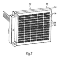
- FIG. 7 an embodiment of a heating device according to the invention is shown.
- This comprises a holding device in the form of a circumferentially closed frame 52, which is formed by two frame shells 54.
- a plurality of mutually parallel layers of identically formed heat-generating elements (for example, according to FIGS. 1 to 4) are received.
- the frame 52 includes a spring, not shown, by which the layer structure is held under pretension in the frame 52.
- all the heat-emitting elements 56 are disposed immediately adjacent to a heat-generating element.
- the heat-emitting elements 56 shown in FIG. 7 are formed by meandering bent aluminum sheet metal strips.
- the heat-generating elements are located between these individual heat-emitting elements 56 and behind the longitudinal struts 58 of the Lucasein- or outlet opening of the frame 52 passing through the grid.
- One of these longitudinal struts 58 is removed in the middle of the frame 52 for the sake of illustration, so that there is a heat generating element 60 can be seen.
- the frame 52 is preferably made of plastic, whereby the electrical insulation can be further improved.
- An additional protection especially against unauthorized contact with the live parts of the heater is additionally provided by the grid, which is also formed of plastic and formed integrally with the frame shells 54.
- a plug connection depart from the power supply and / or control lines through which the heater can be connected in terms of control and Strom machinesshunt in a vehicle.
- a housing is indicated, which in addition to the plug connection may also have control or regulating elements.
Abstract
Description
Die vorliegende Erfindung betrifft ein wärmeerzeugendes Element einer Heizvorrichtung zur Lufterwärmung, umfassend wenigstens ein PTC-Element und an gegenüberliegenden Seitenflächen des PTC-Elementes anliegende elektrische Leiterbahnen. Ein solches wärmeerzeugendes Element ist beispielsweise aus der auf die vorliegende Anmelderin zurückgehenden
Das wärmeerzeugende Element wird insbesondere in einem Zuheizer für ein Kraftfahrzeug eingesetzt und umfasst mehrere in einer Reihe hintereinander angeordnete PTC-Elemente, die über sich parallel zueinander erstreckende, flächig an gegenüberliegenden Seiten der PTC-Elemente anliegende elektrische Leiterbahnen bestromt werden. Die Leiterbahnen sind üblicherweise durch parallele Blechstreifen gebildet. Die so gebildeten wärmeerzeugenden Elemente werden in einer Heizvorrichtung zur Lufterwärmung in einem Kraftfahrzeug eingesetzt, welche mehrere Schichten von wärmeerzeugenden Elementen umfasst, an deren gegenüberliegenden Seiten wärmeabgebende Elemente anliegen. Diese wärmeabgebenden Elemente werden über eine Haltevorrichtung in relativ gutem wärmeübertragenden Kontakt an die wärmeerzeugenden Elemente angelegt.The heat-generating element is used in particular in a heater for a motor vehicle and comprises a plurality of successively arranged in a row PTC elements which are energized via parallel to each other, flat on opposite sides of the PTC elements voltage applied electrical conductors. The conductor tracks are usually formed by parallel metal strips. The heat-generating elements thus formed are used in a heating device for air heating in a motor vehicle, which comprises a plurality of layers of heat-generating elements, abut on the opposite sides of heat-emitting elements. These heat-emitting elements are applied via a holding device in relatively good heat-transfer contact to the heat-generating elements.
Bei dem vorerwähnten Stand der Technik ist eine Halteeinrichtung der Heizvorrichtung durch einen Rahmen gebildet, in dem mehrere parallel zueinander verlaufende Schichten von wärmeerzeugenden und wärmeabgebenden Elementen unter Federvorspannung gehalten sind. Bei einer alternativen Ausgestaltung, die ebenfalls ein gattungsgemäßes wärmeerzeugendes Element sowie eine gattungsgemäße Heizvorrichtung offenbart und die beispielsweise in der
Bei den vorerwähnten wärmeerzeugenden Elementen besteht das Erfordernis, dass die elektrischen Leiterbahnen elektrisch gut mit den PTC-Elementen kontaktiert sein müssen. Andernfalls ergibt sich das Problem eines erhöhten Übergangswiderstandes, welches insbesondere beim Einsatz der wärmeerzeugenden Elemente in Zuheizern für Kraftfahrzeuge wegen der hohen Ströme dazu führen kann, dass eine lokale Überhitzung auftritt. Durch dieses thermische Ereignis kann das wärmeerzeugende Element geschädigt werden. Darüber hinaus handelt es sich bei den PTC-Elementen um selbstregelnde Widerstandsheizer, die mit erhöhter Temperatur eine geringere Wärmeleistung abgeben, so dass eine lokale Überhitzung zur Störung der selbstregelnden Eigenschaften der PTC-Elemente führen kann.In the aforementioned heat generating elements, there is a requirement that the electrical traces must be in good electrical contact with the PTC elements. Otherwise, there is the problem of increased contact resistance, which can lead to a local overheating, in particular when using the heat-generating elements in auxiliary heaters for motor vehicles because of the high currents. By this thermal event, the heat-generating element can be damaged. In addition, the PTC elements are self-regulating resistance heaters that provide lower heat output at elevated temperature, so local overheating can interfere with the self-regulating properties of the PTC elements.
Im übrigen können sich bei hohen Temperaturen im Bereich eines Zuheizers Dämpfe bzw. Gase entwickeln, die zu einer unmittelbaren Gefährdung der in dem Fahrgastraum befindlichen Personen führen können.Moreover, at high temperatures in the range of an auxiliary heater vapors or gases can develop, which can lead to an immediate endangerment of persons located in the passenger compartment.
Entsprechend problematisch ist die Verwendung der gattungsgemäßen wärmeerzeugenden Elemente auch bei hohen Betriebsspannungen, beispielsweise bei Spannungen bis zu 500 V. Hier besteht zum Einen das Problem, dass die die wärmeabgebenden Elemente anströmende Luft Feuchtigkeit und/oder Schmutz mit sich führt, die in die Heizvorrichtung eindringen und hier einen elektrischen Überschlag, d.h. einen Kurzschluss verursachen können. Zum anderen besteht grundsätzlich das Problem, im Bereich der Heizvorrichtung arbeitende Personen vor den stromführenden Teilen der Heizvorrichtung bzw. des wärmeerzeugenden Elementes zu schützen.Accordingly problematic is the use of the generic heat-generating elements even at high operating voltages, for example at voltages up to 500 V. Here, on the one hand the problem that the heat-emitting elements flowing air moisture and / or dirt with it, which penetrate into the heater and here an electric flashover, ie can cause a short circuit. On the other hand, there is basically the problem of protecting persons working in the area of the heating device from the live parts of the heating device or the heat-generating element.
Mit der vorliegenden Erfindung soll ein wärmeerzeugendes Element einer Heizvorrichtung zur Lufterwärmung, sowie eine entsprechende Heizvorrichtung angegeben werden, die eine erhöhte Sicherheit bieten. Dabei will die vorliegende Erfindung insbesondere die Sicherheit hinsichtlich eines möglichen elektrischen Überschlags erhöhen.With the present invention, a heat-generating element of a heating device for air heating, as well as a corresponding heating device are given, which provide increased security. In particular, the present invention aims to increase the safety with regard to a possible electrical flashover.
Zur Lösung dieses Problems wird mit der vorliegenden Erfindung ein gattungsgemäßes wärmeerzeugendes Element dadurch weitergebildet, dass außenseitig an den beiden elektrischen Leiterbahnen eine nicht leitende Isolierschicht vorgesehen ist. Diese Isolierschicht ist eine nicht elektrisch leitende Schicht. Durch die nicht leitende elektrische Isolierschicht sind die großflächigen Ober- und Unterseiten der PTC-Elemente sowie der elektrischen Leiterbahnen an der Außenseite elektrisch abisoliert. So wird verhindert, dass Staub oder Spritzwasser unmittelbar an die stromführenden elektrischen Leiterbahnen gelangt. Im Falle des aus der
Die Isolierschicht sollte vorzugsweise unmittelbar an den elektrischen Leiterbahnen anliegen, so dass der Wärmetransport von den wärmeerzeugenden Elementen zu den wärmeabgebenden Elementen nur in einem geringen Maß beeinträchtigt wird. Die Isolierschicht sollte eine möglichst gute Wärmeleitfähigkeit haben. Angestrebt wird eine Wärmeleitfähigkeit von mehr als 20 W/(m K). Als zweckmäßig im Hinblick auf einen möglichst guten Schutz vor Kurzschluss hat sich eine Isolierschicht mit einer elektrischen Isolation von mehr als 20 kV/mm erwiesen. Die Isolierschicht sollte vorzugweise in Querrichtung des Schichtaufbaus eine elektrische Durchschlagsfestigkeit von wenigstens 2000 V haben.The insulating layer should preferably rest directly on the electrical conductor tracks, so that the heat transfer from the heat-generating elements to the heat-emitting elements is impaired only to a small extent. The insulating layer should have the best possible thermal conductivity. The aim is a thermal conductivity of more than 20 W / (m K). As appropriate in terms of the best possible protection against short circuit, an insulating layer with an electrical insulation of more than 20 kV / mm has been found. The insulating layer should preferably have an electrical breakdown strength of at least 2000 V in the transverse direction of the layer structure.
Aufgrund von praktischen Versuchen der Erfinder hat sich ergeben, dass die Isolierschicht vorzugsweise sowohl eine Keramikplatte als auch eine Kunststofffolie umfassen sollte. Die Kombination beider Elemente kann die geforderten Isolationseigenschaften bestmöglich abbilden. Die Keramikplatte kann beispielsweise aus Aluminiumoxid mit einer Wärmeleitfähigkeit von mehr als 24 W/(m K) und einer elektrischen Isolation von 28 kV/mm gebildet sein. Die Kunststofffolie kann beispielsweise eine Polymidfolie sein, die, wie auch das Aluminiumoxid, eine relativ gute Wärmeleitfähigkeit von 0,45 W/(m K) und eine hinreichende Durchschlagfestigkeit von 4 kV aufweist.From practical experiments of the inventors, it has been found that the insulating layer should preferably comprise both a ceramic plate and a plastic foil. The combination of both elements can best represent the required insulation properties. The ceramic plate can be formed, for example, of aluminum oxide with a thermal conductivity of more than 24 W / (m K) and an electrical insulation of 28 kV / mm. The plastic film may be, for example, a polyimide film, which, like the aluminum oxide, has a relatively good thermal conductivity of 0.45 W / (m K) and a sufficient dielectric strength of 4 kV.
Die Keramikplatte der Isolierschicht kann als relativ glattes Bauteil mit hoher Genauigkeit vollflächig an die elektrische Leiterbahn angelegt werden. Sofern gewünscht, kann die Isolierschicht direkt mit der elektrischen Leiterbahn verklebt werden. Zur Verbesserung der Wärmeleitfähigkeit zwischen der Leiterbahn und der Isolierschicht sollte der Kleber in einer möglichst dünnen Schicht von unter 20 µm vorgesehen sein. Aus gleichen Gründen ist die Kunststofffolie vorzugsweise auf die Keramikplatte auflaminiert. Die Folie hat hierzu vorzugsweise einseitig eine Wachsschicht von zwischen 10 bis 15 µm, die insbesondere unter den Betriebsbedingungen des wärmeerzeugenden Elementes, d.h. bei höheren Temperaturen von ca. 80°C, und beim Anpressen der Isolierschicht gegen die Leiterbahn aufschmilzt und eine effiziente Wärmeübertragung ermöglicht. Hierbei wirkt es förderlich, die Heizvorrichtung aus sich parallel erstreckenden Lagen von wärmeerzeugenden und wärmeabgebenden Elementen in einem Rahmen anzuordnen und diesen Schichtaufbau unter Federvorspannung in dem Rahmen zu halten, wie dies grundsätzlich bereits aus der auf die Anmelderin zurückgehenden
Das wärmeerzeugende Element kann für sich durch mehrere hintereinander angeordnete PTC-Elemente, diese beidseitig bedecken die Leiterbahnen, sowie die Leiterbahnen außenseitig umgebende Isolierschichten gebildet sein. Alle Bauteile dieses Schichtaufbaus können miteinander verbunden, insbesondere verklebt sein. Die elektrisch leitende Isolierschicht sollte hierbei vorzugsweise die elektrische Leiterbahn überragen, so dass sich die elektrisch leitenden und bestromten Bauteile des wärmeerzeugenden Elementes mit Abstand hinter den äußeren, isolierten Kanten des wärmeerzeugenden Elementes befinden, also mit Abstand nach innen versetzt vorgesehen sind. Die elektrische Leiterbahn kann die Isolierschicht lediglich zur Ausbildung einer elektrischen Kontaktierstelle überragen.The heat-generating element may be formed by a plurality of PTC elements arranged one behind the other, which cover the conductor tracks on both sides, and insulating layers surrounding the conductor tracks on the outside. All components of this layer structure can be connected to one another, in particular adhesively bonded. In this case, the electrically conductive insulating layer should preferably project beyond the electrical conductor track so that the electrically conductive and energized components of the heat-generating element are at a distance behind the outer, insulated edges of the heat-generating element, that is to say offset at a distance from the inside. The electrical conductor can project beyond the insulating layer only to form an electrical contact point.
Um auch den Zugang zu den stromführenden Teilen des wärmeerzeugenden Elementes zwischen den Isolierschichten zu vermeiden, und insbesondere zur genauen Positionierung der PTC-Elemente, wird gemäß einer weiteren bevorzugten Ausgestaltung der vorliegenden Erfindung vorgeschlagen, an dem wärmeerzeugenden Element einen an sich bekannten Positionsrahmen vorzusehen, der eine Rahmenöffnung zur Aufnahme des wenigstens einen PTC-Elementes ausbildet. Dieser an sich bekannter Positionsrahmen ist beispielsweise in der vorerwähnten
Im Hinblick auf die Anwendung relativ hoher Spannungen wird erfindungsgemäß vorgeschlagen, dass die Isolierschicht zumindest in Querrichtung des länglichen Rahmens die Leiterbahn überragt, wobei die elektrischen Leiterbahnen und das wenigstens eine PTC-Element umfänglich von dem Positionsrahmen durch einen Isolierspalt beabstandet sind. Es hat sich gezeigt, dass bei der Anwendung hoher Spannungen ein elektrischer Überschlag durch das thermoplastische Material des Positionsrahmens nicht immer vermieden werden kann, wenn die elektrisch leitenden Teile unmittelbar benachbart zu oder an dem Positionsrahmen anliegen. Die bevorzugte Weiterbildung mit dem lsolierspalt schafft hier Abhilfe vor der Gefahr eines elektrischen Überschlags, indem ein hinreichend großer Spalt zwischen den stromführenden Teilen und dem Material des Positionsrahmens verwirklicht wird. Zur Einhaltung dieses Isolierspaltes kann beispielsweise die Isolierschicht fest mit den stromführenden Teilen des wärmeerzeugenden Elementes verbunden sein und wiederum gegenüber dem Positionsrahmen fixiert sein. So ist es beispielsweise möglich, die Isolierschicht zumindest in Breitenrichtung, d.h. quer zur Längserstreckung des länglichen wärmeerzeugenden Elementes, mit Abschnitten auszubilden, die die stromführenden Teile, insbesondere die elektrische Leiterbahn, in Breitenrichtung überragen. Diese überragenden Abschnitte der Isolierschicht sind vorzugsweise mit den Positionsrahmen verbunden, beispielsweise über eine Klebeschicht. Mit einer solchen Ausgestaltung können beispielsweise die stromführenden Teile des wärmeerzeugenden Elementes, d.h. das PTC-Element sowie die an diesen gegenüberliegend anliegenden Leiterbahnen, vollständig gekapselt werden. Die Isolierschicht deckt die stromführenden Teile beidseitig ab und schließt dichtend an die Ränder des Positionsrahmens an. Hierdurch wird eine elektrisch nicht leitende Umkapselung in Umfangsrichtung des wärmeerzeugenden Elementes gebildet. Bei einer Querschnittsansicht des wärmeerzeugenden Elementes befinden sich bei dieser bevorzugten Ausgestaltung die bestromten Teile, d.h. die elektrischen Leiterbahnen und die dazwischen angeordneten PTC-Elemente, in der Mitte. Dieser Schichtaufbau wird ober- und unterseitig begrenzt durch die Isolierschicht. Diese wiederum liegt mit ihren äußeren Rändern jeweils dichtend an dem aus Kunststoff gebildeten Positionsrahmen an. Bei dieser bevorzugten Ausgestaltung besteht keinerlei Möglichkeit, dass Feuchtigkeit oder Verschmutzung, die durch das wärmeerzeugende Element anströmende Luft verschleppt wird, an die stromführenden Teile gelangen kann. Bei dieser bevorzugten Ausgestaltung können lediglich die stromführenden Teile, speziell die Kontaktbleche, die Isolierschicht an einer oder beiden Stirnseiten des wärmeerzeugenden Elementes überragen. Dort sind die elektrischen Leiterbahnen indes regelmäßig in der Halteeinrichtung der Heizvorrichtung aufgenommen und durch die strukturellen Elemente dieser Halteeinrichtung können die stromführenden Teile gegenüber der anströmenden Luft abgedichtet werden.With regard to the application of relatively high voltages, it is proposed according to the invention that the insulating layer projects beyond the conductor track at least in the transverse direction of the elongate frame, wherein the electrical conductor tracks and the at least one PTC element are circumferentially spaced from the position frame by an insulating gap. It has been found that with the use of high voltages, an electrical flashover by the thermoplastic material of the position frame can not always be avoided when the electrically conductive parts abut directly adjacent to or on the position frame. The preferred development with the insulating gap here provides relief from the risk of electrical flashover by a sufficiently large gap between the current-carrying parts and the material of the position frame is realized. To comply with this insulating gap, for example, the insulating layer can be firmly connected to the current-carrying parts of the heat-generating element and in turn fixed relative to the position frame. Thus, for example, it is possible to form the insulating layer at least in the width direction, ie transversely to the longitudinal extent of the elongate heat-generating element, with sections which project beyond the current-carrying parts, in particular the electrical conductor track in the width direction. These protruding portions of the insulating layer are preferably connected to the position frames, for example via an adhesive layer. With such a configuration, for example, the current-carrying parts of the heat-generating element, that is, the PTC element as well as the adjacent thereto conductor tracks, are completely encapsulated. The insulating layer covers the current-carrying parts on both sides and closes sealingly against the edges of the position frame on. As a result, an electrically non-conductive encapsulation in the circumferential direction of the heat-generating element is formed. In a cross-sectional view of the heat-generating element are in this preferred embodiment, the energized parts, ie, the electrical conductors and the interposed PTC elements in the middle. This layer structure is bounded on top and bottom by the insulating layer. This in turn bears with its outer edges each sealingly on the position of the plastic frame formed. In this preferred embodiment, there is no possibility that moisture or contamination, which is entrained by the heat-generating element inflowing air, can reach the live parts. In this preferred embodiment, only the current-carrying parts, especially the contact sheets, can project beyond the insulating layer on one or both end sides of the heat-generating element. There, however, the electrical conductor tracks are regularly added to the holding device of the heater and by the structural elements of this holding device, the current-carrying parts can be sealed against the incoming air.
Die elektrisch nicht leitende Umkapselung wird vorzugsweise dadurch geschaffen, dass die die elektrische Leiterbahn überragenden Abschnitte der Isolierschicht unter Zwischenlage eines Dichtelementes gegenüber dem Positionsrahmen abgedichtet ist. Das Dichtelement ist vorzugsweise aus einem isolierenden Material gebildet, beispielsweise einem elastischen Kunststoff. Vorzugsweise wird das Dichtelement indes durch einen den Positionsrahmen und die Isolierschicht verbindenden Kunststoffkleber gebildet, so dass nicht nur eine umfängliche Kapselung der stromführenden Teile bewirkt wird, sondern darüber hinaus auch die stromführenden Teile zusammen mit den an diesen befestigten Isolierschichten zusammen mit dem Positionsrahmen zu einer baulichen Einheit verbunden sind.The electrically non-conductive encapsulation is preferably created by the fact that the sections of the insulating layer which project beyond the electrical trace are sealed with the interposition of a sealing element in relation to the position frame. The sealing element is preferably formed of an insulating material, for example an elastic plastic. Preferably, however, the sealing element is formed by a plastic adhesive connecting the position frame and the insulating layer, so that not only a circumferential encapsulation of the current-carrying parts is effected, but also the current-carrying parts together with the insulating layers attached thereto together with the position frame to a structural Unit are connected.
Es sei darauf hingewiesen, dass der Positionsrahmen aus einem elektrisch hochwertigen Isoliermaterial bestehen kann und dass vollkommen auf die Verwendung eines üblichen thermoplastischen Materials verzichtet wird. So kann beispielsweise der Positionierrahmen durch ein einheitliches Silikonbauteil gebildet sein. Ebenso ist es möglich, den Positionierrahmen durch Einspritzen einer hochisolierenden, vorzugsweise klebend abdichtenden Masse zwischen die an den gegenüberliegenden Seitenflächen der PTC-Elemente anliegenden Schichten auszubilden. In einem solchen Fall können die PTC-Elemente gegenüber den übrigen Schichten des Schichtaufbaus zu Montagezwecken positioniert und durch Einspritzen der hochisolierenden Masse endgültig in ihrer Lage festgelegt werden. Der Positionsrahmen dient in einem solchen Fall nicht als Positionierhilfe bei der Montage, sondern lediglich zur Sicherstellung einer vorbestimmten Position des oder der PTC-Elemente beim dauerhaften Betrieb des wärmeabgebenden Elementes.It should be noted that the position frame can be made of an electrically high-quality insulating material and that completely dispenses with the use of a conventional thermoplastic material. For example, the positioning frame may be formed by a uniform silicone component. It is also possible, the positioning frame by injecting a highly insulating, preferably adhesive sealing compound between the at the opposite side surfaces of the PTC elements form adjacent layers. In such a case, the PTC elements can be positioned with respect to the remaining layers of the layer structure for assembly purposes and finally fixed in position by injecting the highly insulating mass. The position frame is not used in such a case as a positioning aid during assembly, but only to ensure a predetermined position of the PTC elements or the permanent operation of the heat-emitting element.
Sofern der Positionsrahmen als spritzgegossenes Bauteil aus einem hochwertigen elektrischen Isoliermaterial gebildet und als Positionierhilfe bei der Montage verwendet wird, können durch Einbringen eines Klebestoffes zwischen die einander gegenüberliegenden und an den PTC-Element anliegenden Schichten diese zusammen mit den PTC-Elementen und den Silikonrahmen zu einer baulichen Einheit verklebt werden. Auch in einem solchen Fall kann auf ein konventionelles Spitzgießteil aus einem üblichen Thermoplasten zur Ausbildung des Positionsrahmens verzichtet werden.If the position frame is formed as an injection-molded component from a high-quality electrical insulation material and used as a positioning aid during assembly, by introducing an adhesive between the opposing layers and adjacent to the PTC element these together with the PTC elements and the silicone frame to a structural unit to be glued. Even in such a case can be dispensed with a conventional Spitzgießteil from a conventional thermoplastic for forming the position frame.
Die elektrische Leiterbahn wird vorzugsweise durch ein Kontaktblech gebildet, welches das zumindest eine PTC-Element überragt. Durch das Kontaktblech wird an der das zumindest eine PTC-Element überragenden Seite wenigstens eine elektrische Kontaktierstelle in Form eines Steckerelementes ausgebildet, durch das der elektrische Anschluss des wärmeerzeugenden Elementes an eine Stromversorgung erfolgen kann. Dementsprechend überragt das Kontaktblech das PTC-Element vorzugsweise zumindest an der Stirnseite des wärmeerzeugenden Elementes. Allerdings ist es ebenso möglich, das Kontaktblech so auszubilden, dass dieses das PTC-Element in Breitenrichtung überragt.The electrical conductor track is preferably formed by a contact plate, which projects beyond the at least one PTC element. At least one electrical contacting point in the form of a plug element is formed by the contact plate on the side projecting beyond the at least one PTC element, through which the electrical connection of the heat-generating element to a power supply can take place. Accordingly, the contact plate preferably projects beyond the PTC element at least on the end face of the heat-generating element. However, it is also possible to design the contact plate such that it projects beyond the PTC element in the width direction.
Vorzugsweise werden die stromführenden Kontaktbleche insbesondere dazu genutzt, die PTC-Elemente innerhalb der durch den Positionsrahmen gebildeten Rahmenöffnung zu halten. Dementsprechend erstreckt sich zwischen den einander gegenüberliegenden überragenden Enden der Kontaktbleche ein Abschnitt des Halterahmens. Mit anderen Worten ist der Halterahmen auch zwischen den einander gegenüberliegenden Kontaktblechen vorgesehen, so dass die stromführenden Teile des wärmeerzeugenden Elementes innerhalb bestimmter Grenzen in dem Positionsrahmen in Höhenrichtung gehalten sind. Die Einhaltung des Isolierspaltes zwischen den Kontaktblechen und dem Material des Positionsrahmens kann beispielsweise durch ein isolierendes Abstandsmittel bewirkt werden, das in dem Isolationsspalt zwischen dem das PTC-Element überragenden Rand des Kontaktblechs und dem Material des Positionsrahmens vorgesehen ist. Vorzugsweise erstreckt sich dieses Abstandsmittel in Querrichtung des Positionsrahmens bis zu dem äußeren Ende des Kontaktblechs. Das isolierende Abstandsmittel wird vorzugsweise durch ein Kunststoffmaterial gebildet, welches eine höhere elektrische Durchschlagfestigkeit als das Material des Positionsrahmens hat (z.B. Silikon, Polyurethan).Preferably, the current-carrying contact sheets are used in particular to hold the PTC elements within the frame opening formed by the positioning frame. Accordingly, a portion of the support frame extends between the opposing projecting ends of the contact sheets. In other words, the holding frame is also provided between the opposing contact plates, so that the current-carrying parts of the heat-generating element held within certain limits in the position frame in the height direction are. Compliance with the Isolierspaltes between the contact plates and the material of the position frame can be effected, for example, by an insulating spacer means which is provided in the insulating gap between the PTC element projecting edge of the contact plate and the material of the positioning frame. Preferably, this spacing means extends in the transverse direction of the positioning frame to the outer end of the contact sheet. The insulating spacer means is preferably formed by a plastic material which has a higher electrical breakdown strength than the material of the positional frame (eg silicone, polyurethane).
Fallgestaltungen sind denkbar, bei denen das bzw. die PTC-Elemente in der Rahmenöffnung lose zwischen den beiden Kontaktblechen gehalten sind. Diese Fallgestaltung wird insbesondere dann zu treffen sein, wenn aus Gründen einer guten elektrischen Kontaktierung zwischen den PTC-Elementen und dem Kontaktblech auf eine Verklebung zwischen beiden Teilen verzichtet wird. Um dann eine direkte Anlage der PTC-Elemente an dem die Rahmenöffnung umgebenden Material des Positionsrahmens zu vermeiden und um eine sichere Einhaltung des lsolierspaltes sicherzustellen, wird gemäß einer bevorzugten Weiterbildung der vorliegenden Erfindung vorgeschlagen, dass sich das isolierende Abstandsmittel bis über den diese Rahmenöffnung umfänglich umgebenden Rand erstreckend ausgebildet ist. Das isolierende Abstandsmittel befindet sich dementsprechend in der die PTC-Elemente aufnehmenden Ebene und unmittelbar benachbart zu einer dem Positionsrahmen gegenüber liegenden Stirnseite des PTC-Elementes.Case designs are conceivable in which the PTC element or elements are held loosely in the frame opening between the two contact plates. This case design is to be taken in particular if, for reasons of good electrical contact between the PTC elements and the contact plate is dispensed with an adhesive bond between the two parts. In order to avoid a direct contact of the PTC elements on the material surrounding the frame opening of the position frame and to ensure a safe adherence to the insulation gap, it is proposed according to a preferred development of the present invention that the insulating spacer means surrounds the circumference surrounding this frame opening Edge is formed extending. Accordingly, the insulating spacer means is located in the plane receiving the PTC elements and immediately adjacent to an end face of the PTC element opposite the position frame.
Das Dichtelement erstreckt sich zumindest in Längsrichtung des Positionsrahmens. Im Hinblick auf eine möglichst genaue Anordnung und Positionierung des Dichtelementes, insbesondere in Bezug auf die überragenden Enden der Isolierschicht, wird dieses benachbart zu einem Dichtmittelbegrenzungsrand vorgesehen, der sich in Längsrichtung des Positionsrahmens vorzugsweise durchgehend erstreckt und durch den Positionsrahmen ausgebildet ist. Dieser Dichtmittelbegrenzungsrand erstreckt sich in Höhenrichtung des Positionsrahmens, d.h. in einer Richtung, die sowohl rechtwinklig zu der Querrichtung des Positionsrahmens als auch senkrecht zu der Längsrichtung des Positionsrahmens ausgerichtet ist. Der Dichtmittelbegrenzungsrand soll sich vorzugsweise über die gesamte Längserstreckung des Positionsrahmens erstrecken, d.h. das Dichtelement an den gegenüberliegenden Längsseiten des Positionsrahmens fassen.The sealing element extends at least in the longitudinal direction of the position frame. With a view to the most accurate arrangement and positioning of the sealing element, in particular with respect to the projecting ends of the insulating layer, this is provided adjacent to a Dichtmittelbegrenzungsrand, which preferably extends continuously in the longitudinal direction of the positioning frame and is formed by the position frame. This sealant-limiting edge extends in the height direction of the positioning frame, that is, in a direction which is aligned both perpendicular to the transverse direction of the positioning frame and perpendicular to the longitudinal direction of the positioning frame. The Dichtmittelbegrenzungsrand should preferably via extend the entire longitudinal extension of the position frame, ie the sealing element on the opposite longitudinal sides of the position frame grasp.
In gleicher Richtung und im Hinblick auf eine möglichst genaue Positionierung der Isolierschicht erstreckt sich in Höhenrichtung vorzugsweise ein Begrenzungsrand, der in Höhenrichtung jedenfalls bis zu der Ebene reicht, in der sich die Isolierschicht befindet. Zwischen einander gegenüberliegenden Begrenzungsrändern sind dementsprechend die jeweiligen Isolierschichten vorgesehen. Dabei wird im Hinblick auf eine möglichst hohe Sicherheit gegen elektrischen Durchschlag auch das stirnseitige Ende der lsolierschicht mit Abstand zu den lsolierschichtbegrenzungsrändern angeordnet. Da die Isolierschicht indes kein eigentlich elektrisch leitendes Bauteil ist, kann es aber mit Rücksicht auf eine rationelle Fertigung durchaus toleriert werden, dass die Isolierschicht den Begrenzungsrand an einer Seite unmittelbar kontaktiert. Die Begrenzungsränder dienen vornehmlich der genauen Positionierung der Isolierschicht in Breitenrichtung des Positionsrahmens.In the same direction and in view of the most accurate positioning of the insulating layer extending in the height direction preferably has a boundary edge, which extends in the height direction in any case up to the level in which the insulating layer is located. Between opposite boundary edges, the respective insulating layers are accordingly provided. In this case, the front end of the insulating layer is arranged at a distance from the insulating boundary edges with a view to the highest possible safety against electrical breakdown. However, since the insulating layer is not actually an electrically conductive component, it can certainly be tolerated with regard to a rational production that the insulating layer directly contacts the boundary edge on one side. The boundary edges are mainly used for the exact positioning of the insulating layer in the width direction of the position frame.
Zusätzlich zu diesen sich in Höhenrichtung erstreckenden Montagehilfen bzw. Anlagerändern weist der Positionsrahmen vorzugsweise sich ebenfalls in Höhenrichtung, d.h. in einer Richtung quer zur Lagerebene des PTC-Elementes erstreckende Begrenzungsstege auf. Diese Begrenzungsstege überragen die Begrenzungsränder und dienen der Positionierung eines an dem wärmeerzeugenden Element anliegenden wärmeabgebenden Elements. Dieses liegt unter Zwischenlage der Isolierschicht an der elektrischen Leiterbahn an.In addition to these vertically extending mounting aids, the positioning frame preferably also extends in the vertical direction, i. in a direction transverse to the bearing plane of the PTC element extending boundary webs. These boundary webs project beyond the boundary edges and serve to position a heat-emitting element adjacent to the heat-generating element. This lies with the interposition of the insulating layer on the electrical conductor.
Während die Begrenzungsränder sowie die Begrenzungsstege der Positionierung der Isolierschicht bzw. der wärmeabgebenden Elemente in Querrichtung des Positionsrahmens dienen wird, auch im Hinblick auf eine möglichst genaue Positionierung der verschiedenen Bauteile des wärmeerzeugenden Elementes bei der Herstellung desselben gemäß einer weiteren bevorzugten Ausgestaltung vorgeschlagen, an dem Positionierrahmen wenigstens einen sich quer zu der Lagerebene des PTC-Elementes, d.h. einen sich in Höhenrichtung erstreckenden Fixiersteg vorzusehen, welcher der Fixierung der Isolierschicht in Längsrichtung des Positionsrahmens dient. Aufgrund der Isolierschichtbegrenzungsränder und des Fixiersteges wird die Isolierschicht bei der Montage relativ zu den Positionsrahmen fixiert. Die Isolierschicht wird danach zuverlässig innnerhalb vorgegebener Grenzen in Quer- bzw. Längsrichtung angeordnet.While the boundary edges and the boundary webs of the positioning of the insulating layer or the heat-emitting elements will serve in the transverse direction of the position frame, also proposed with regard to the most accurate positioning of the various components of the heat-generating element in the production of the same according to another preferred embodiment, on the positioning frame at least one transverse to the bearing plane of the PTC element, ie, to provide a vertically extending fixing web, which serves to fix the insulating layer in the longitudinal direction of the position frame. Due to the Isolierschichtbegrenzungsränder and the Fixiersteges the insulating layer during installation is relatively fixed to the frame. The insulating layer is then reliably arranged within predetermined limits in the transverse or longitudinal direction.
Zur lagegenauen Positionierung der elektrischen Leiterbahn, die vorzugsweise durch ein Kontaktblech gebildet ist, weist der Positionsrahmen ferner sich in Höhenrichtung, d.h. quer zur Lagerebene des PTC-Elementes erstreckende Zapfen auf. Jeder der Zapfen ist passgenau in einer Ausnehmung im Eingriff, die in dem Kontaktblech ausgespart ist. Durch Anschmelzen des Zapfens ist oberhalb des Kontaktbleches eine Verdickung gebildet, durch welche das Kontaktblech an dem Positionsrahmen gesichert ist. Bei dieser Ausgestaltung ist durch den Formschluss von Zapfen und Ausnehmung das Kontaktblech exakt positioniert. Die Verdickung sichert das Kontaktblech gegenüber dem Positionsrahmen formschlüssig. Die Isolierschicht wird auf die so gebildete Einheit vorzugsweise aufgeklebt, wobei die Klebeverbindung sich vorzugsweise zwischen dem Positionsrahmen und der Isolierschicht befindet.For positionally accurate positioning of the electrical conductor, which is preferably formed by a contact plate, the position frame further comprises in the height direction, i. transverse to the bearing plane of the PTC element extending pin. Each of the pins is precisely in engagement in a recess which is recessed in the contact plate. By melting the pin, a thickening is formed above the contact plate, through which the contact plate is secured to the position frame. In this embodiment, the contact plate is accurately positioned by the positive connection of pin and recess. The thickening secures the contact plate with respect to the position frame form-fitting. The insulating layer is preferably adhered to the unit so formed, wherein the adhesive connection is preferably between the position frame and the insulating layer.
Auf diese Weise kann eine den Positionsrahmen, das wenigstens eine PTC-Element sowie die Kontaktbleche und die Isolierschichten, umfassende vormontierte bauliche Einheit gebildet werden. Beim späteren Zusammenführen des wärmeerzeugenden Elementes mit dem wärmeabgebenden Element muss in den späteren Verfahrensschritten nicht mehr dafür Sorge getragen werden, dass die einzelnen Schichten des wärmeerzeugenden Elementes lagegenau im Rahmen der Entmontage positioniert werden.In this way, a preassembled structural unit comprising the positional frame, the at least one PTC element and the contact sheets and the insulating layers can be formed. During the later merging of the heat-generating element with the heat-emitting element no longer has to be taken in the later steps that the individual layers of the heat-generating element are accurately positioned in the context of Entmontage.
Gemäß einer bevorzugten Weiterbildung bildet das Kontaktblech jedenfalls an einer seiner Stirnseiten einen Steckeranschluss aus, der durch Blechbearbeitung als einteiliges Element an dem Kontaktblech ausgebildet ist und derart umgeformt worden ist, dass er sich quer zu der Blechebene erstreckt. Dieser Steckeranschluss befindet sich bei der erwähnten Weiterbildung in einem Schlitz, der an dem Positionsrahmen ausgespart ist und sich nach außen zu einer Stirnseite des Positionsrahmens öffnet. Durch diese Ausgestaltung ist an der Stirnseite des Positionsrahmens jedenfalls ein elektrischer Steckeranschluss ausgebildet, der in die Halteeinrichtung einer Heizvorrichtung eingeschoben werden kann, um das wärmeerzeugende Element mit der Stromversorgung zu verbinden.In any case, according to a preferred development, the contact plate forms on one of its end faces a plug connection which is formed by sheet metal processing as a one-part element on the contact plate and has been reshaped such that it extends transversely to the plane of the sheet. This plug connection is located in the aforementioned development in a slot which is recessed on the positioning frame and opens outwards to an end face of the position frame. By this configuration, an electrical plug connection is in any case formed on the end face of the position frame, which can be inserted into the holding device of a heating device in order to connect the heat-generating element to the power supply.
Vorzugsweise befinden sich an der Stirnseite zwei Schlitze und es greifen die einander gegenüberliegenden Kontaktbleche mit ihren jeweils durch Blechbearbeitung ausgebildeten Steckeranschlüssen in die jeweiligen, an den Positionsrahmen ausgesparten Schlitze ein.Preferably, there are two slots on the front side and it grip the opposing contact plates with their respectively formed by sheet metal processing plug connections in the respective, recessed on the positioning frame slots.
Bei einer alternativen Ausgestaltung ist der Steckeranschluss durch Blechbearbeitung des Kontaktblechs jedenfalls an seiner Stirnseite ausgeformt. Der Steckeranschluss erstreckt sich vorzugsweise parallel zu dem übrigen Kontaktblech, jedoch befindet er sich durch Umbiegen in einer Ebene, die gegenüber der das Kontaktblech enthaltenden Ebene nach außen beabstandet ist. Diese bevorzugte Ausgestaltung eignet sich insbesondere für solche Fallgestaltungen, bei denen die beiden Kontaktbleche an der gleichen Stirnseite elektrische Anschlusselemente ausbilden, die im Hinblick auf eine möglichst sichere Isolierung und den Platzbedarf von Steckeraufnahmen für die Anschlüsse weit voneinander beabstandet sein sollen.In an alternative embodiment, the plug connection is formed by sheet metal processing of the contact plate in any case at its end face. The male terminal preferably extends parallel to the remainder of the contact sheet, but is bent over in a plane spaced outwardly from the plane containing the contact sheet. This preferred embodiment is particularly suitable for such situations in which the two contact plates on the same end side form electrical connection elements that should be widely spaced from each other with regard to the most secure insulation and space requirements of connector receptacles for the connections.
Die erfindungsgemäße Heizvorrichtung weist mehrere wärmeerzeugende Elemente der vorstehend genannten Art sowie mehrere in parallelen Schichten angeordnete wärmeabgebende Elemente auf. Diese wärmeabgebenden Elemente sind an gegenüberliegenden Seiten eines wärmeabgebenden Elementes angelegt. So kann beispielsweise bei der Ausführungsform nach der
Die erfindungsgemäße Heizvorrichtung wird weitergebildet durch die bereits vorstehend unter Bezugnahme auf das wärmeerzeugende Element diskutierten Weiterbildung.The heating device according to the invention is further developed by the development discussed above with reference to the heat-generating element.
Weitere Einzelheiten und Vorteile der vorliegenden Erfindung ergeben sich aus der nachfolgenden Beschreibung von Ausführungsbeispielen in Verbindung mit der Zeichnung. In dieser zeigen:
- Fig. 1
- eine perspektivische Seitenansicht auf ein Ausführungsbeispiel eines wärmeerzeugenden Elementes in Explosionsdarstellung;
- Fig. 2
- eine Draufsicht aus dem in Fig. 1 gezeigten Ausführungsbeispiel;
- Fig. 3
- eine Querschnittsansicht entlang der Linie III-III gemäß der Darstellung in Fig. 2;
- Fig. 4
- eine perspektivische Seitenansicht des in den Fig. 1 bis 3 gezeigten Ausführungsbeispiels in zusammengebautem Zustand;
- Fig. 5
- eine perspektivische Seitenansicht eines weiteren Ausführungsbeispiels eines wärmeerzeugenden Elementes;
- Fig. 6
- eine Querschnittsansicht entlang der Linie V-V gemäß der Darstellung in Fig. 4 und
- Fig. 7
- eine perspektivische Seitenansicht eines Ausführungsbeispiels einer Heizvorrichtung.
- Fig. 1
- a side perspective view of an embodiment of a heat generating element in exploded view;
- Fig. 2
- a plan view of the embodiment shown in Figure 1;
- Fig. 3
- a cross-sectional view taken along the line III-III as shown in Fig. 2;
- Fig. 4
- a side perspective view of the embodiment shown in Figures 1 to 3 in the assembled state.
- Fig. 5
- a side perspective view of another embodiment of a heat generating element;
- Fig. 6
- a cross-sectional view along the line VV as shown in Fig. 4 and
- Fig. 7
- a perspective side view of an embodiment of a heater.
In Fig. 1 ist eine perspektivische Seitenansicht der wesentlichen Teile eines Ausführungsbeispiels eines wärmeerzeugenden Elementes in Explosionsdarstellung gezeigt. Das wärmeerzeugende Element weist einen aus Kunststoff spritzgegossenen Positionsrahmen 2 auf, dessen Mittellängsachse eine Symmetrieebene des wärmeerzeugenden Elementes ausbildet. Dieses ist im Wesentlichen spiegelsymmetrisch ausgebildet und weist an jeder Seite des Positionsrahmens 2 zunächst vorgesehene Kontaktbleche 4 auf, die zwischen sich in dem Positionsrahmen 2 aufgenommene PTC-Elemente 6 aufnehmen. An der Außenseite der Kontaktbleche 4 befindet sich eine zweilagige lsolierschicht 8, umfassend eine äußere Isolierfolie 10 und eine innere, unmittelbar an dem Kontaktblech 4 anliegende Keramikplatte 12. Die Keramikplatte 12 ist eine relativ dünne Aluminiumoxidplatte, die eine sehr gute elektrische Durchschlagfestigkeit von etwa 28 kV/mm und eine gute Wärmeleitfähigkeit von mehr als 24 W/(m K) bereitstellt. Die Kunststofffolie 10 ist vorliegend durch eine Polymidfolie gebildet, die eine gute Wärmeleitfähigkeit von etwa 0,45 W/(m K) und eine Durchschlagfestigkeit von 4 kV hat. Zwischen der Kunststofffolie 10 und der Keramikplatte 12 befindet sich eine wenige µm starke Wachsschicht, deren Schmelzpunkt mit Rücksicht auf die Betriebstemperatur des wärmeerzeugenden Elementes abgestimmt ist, und zwar derart, dass das Wachs bei Betriebstemperatur aufschmilzt und sich zwischen der Kunststofffolie und der Keramikplatte 12, die unter Druckbeanspruchung aneinander anliegen, so verteilt, dass ein ausgleichender Film geschaffen ist, der eine gute Wärmeübertragung zwischen den beiden Teilen 10, 12 der Isolierschicht 8 begünstigt. Die Kombination von Kunststofffolie 10 und Keramikplatte 12 führt zu einem Isolierteil 8, welches gute elektrische Eigenschaften und Wärmeleiteigenschaften hat und insbesondere gegenüber Spannungen von bis zu 2000 V durchschlagfest ist, welches aber gleichzeitig auch die notwendige Festigkeit zeigt. Durch die außenliegende Isolierfolie werden eventuelle Spannungsspitzen, die insbesondere bei durch Druck gegen das wärmeerzeugende Element anliegende wärmeabgebenden Elemente erzeugt werden kann, abgebaut und vergleichmäßigt. Der zwischen beiden Teilen 10, 12 der Isolierschicht angeordnete Wachs, gegebenenfalls auch ein zusätzlich dort vorgesehener und beide Teile 10, 12 miteinander verbindender Kleber begünstigt diesen Abbau von Spannungsspitzen. Dementsprechend besteht auch bei höheren Druckspannungen, die einen Schichtaufbau aus wärmeerzeugenden und wärmeabgebenden Elementen unter Vorspannung halten, nicht die Gefahr, das die relativ spröde Keramikschicht bricht.In Fig. 1 is a side perspective view of the essential parts of an embodiment of a heat generating element is shown in exploded view. The heat generating element has a molded
Die Isolierschicht 8 ist vorzugsweise auf die Außenseite des Kontaktblechs 4 aufgeklebt. Dieses befindet sich in etwa mittig unter der Isolierschicht 8 und ist mit geringerer Breite als die Isolierschicht 8 ausgebildet. Allerdings überragt das jeweilige Kontaktblech 4 die Isolierschicht 8 an den Stirnseiten. Das Kontaktblech 4 ist an diesen die Isolierschicht 8 überragenden Enden zunächst in seiner Breite deutlich vermindert. An den in Fig. 1 rechtem Ende weist das Kontaktblech 4 einen durch Freischneiden gegenüber der Breite des Kontaktbleches 4 verjüngten Befestigungssteg 14 auf, in dem eine Ausnehmung 16 ausgespart ist. An dem gegenüberliegenden, in Bezug auf Fig. 1 linken Ende, ist ebenfalls ein entsprechender verjüngter Befestigungssteg 18 mit einer Ausnehmung 16 vorgesehen. Von dem seitlichen Rand dieses Befestigungssteges 18 geht ein aus der Ebene des Kontaktbleches 4 herausgebogener Steg 20 ab, der die Basis eines den Positionsrahmen 2 stirnseitig überragenden Steckeranschluss 22 bildet.The insulating
Der Steg 20 ist in einem an dem Positionsrahmen 2 ausgesparten Schlitz 24 im Eingriff, der sich zu der Stirnseite des Positionsrahmens 2 hin öffnet. Der Positionsrahmen 2 weist ferner an seinen stirnseitigen Endbereichen Zapfen 26 auf, die sich in Höhenrichtung des wärmeerzeugenden Elementes erstrecken, d. h. rechtwinklig von der Oberfläche des Positionsrahmens 2 abgehen. Bei der Montage werden diese Zapfen 26 in die Ausnehmungen 16 eingeführt. Danach wird der Zapfen 26 zur Ausbildung einer Schmelzverdickung angeschmolzen und das Kontaktblech 4 auf diese Weise gegenüber dem Positionsrahmen 2 gesichert. Wie insbesondere in Fig. 1 und 4 zu entnehmen ist, weist der Positionsrahmen 2 neben den Zapfen 26 weitere Positionierungshilfen zur lagegenauen Anordnung des Kontaktbleches 4 an dem Positionsrahmen 2 auf. So bildet der Positionsrahmen 2 zum einen an den stirnseitigen Enden des Kontaktbleches 4 stirnseitige Fixierstege 28 aus, die sich leicht bis über die Oberseite des Kontaktbleches 4 erstrecken und deren Abstand zueinander in etwa der Länge des Kontaktbleches 4 entspricht. Hierdurch ist das Kontaktblech 4 in Längsrichtung positioniert. In Querrichtung bildet der Positionsrahmen 2 zum anderen sich über nahezu die gesamte Längserstreckung des Kontaktbleches 4 erstreckende Begrenzungsränder 30 aus, die sich ebenfalls bis über die Oberseite des Kontaktbleches 4 erstrecken und deren Abstand zueinander ein wenig größer als die Breite des Kontaktbleches 4 ist. Dieser Begrenzungsrand 30 wird beiderseits durch Begrenzungsstege 32 mit innenliegenden Rastvorsprüngen überragt, durch welche ein an dem wärmeerzeugenden Element anzuordnendes wärmeabgebendes Element zu Montagezwecken fixiert werden kann.The
In dem wärmeerzeugenden Element liegen - wie sich aus Fig. 3 ergibt - gegenüberliegende Oberflächen der PTC-Elemente 6 an den Innenflächen der Kontaktbleche 4 an und sind in einer Rahmenöffnung 34 des Positionsrahmens 2 fixiert. Wie sich aus Fig. 1 ergibt, befinden sich jeweils sechs PTC-Elemente 6 innerhalb einer Rahmenöffnung 34. Es sind zwei in Längsrichtung hintereinander angeordnete gleichgroße Rahmenöffnungen 34 vorgesehen. Die Packung der PTC-Elemente ist gegenüber dem Material des Positionsrahmens 2 durch einen lsolierspalt 36 beabstandet. Dieser lsolierspalt 36 erstreckt sich auch in einer Richtung parallel zu der Lagerebene zwischen der Innenseite des Kontaktbleches 4 und einem verjüngten Innenrand 38 des Positionsrahmens, der die Rahmenöffnung 34 umfänglich umgibt. Durch den Isolierspalt 38 sind danach die stromführenden Teile des wärmeerzeugenden Elementes, d. h. die beiden Kontaktbleche 4 und die PTC-Elemente 6 von dem Material des Positionsrahmens 2 beabstandet. Dieser Abstand wird bei dem gezeigten Ausführungsbeispiel der Fig. 1 bis 4 durch ein isolierendes Abstandsmittel 40 gesichert, welches das vordere Ende des Innenrandes 38 umfänglich umgibt. Das isolierende Abstandsmittel 40 ist bei dem gezeigten Ausführungsbeispiel durch einen Silikonstreifen gebildet, der den vorderen Bereich des Innenrandes 38 in sich aufnimmt und diesen umfänglich umgibt.In the heat-generating element are - as is apparent from Fig. 3 - opposite surfaces of the
Es ist nicht zwingend erforderlich, dass die stromführenden Teile des wärmeerzeugenden Elementes unmittelbar an dem isolierenden Abstandsmittel 40 anliegen. Vielmehr soll das Abstandsmittel lediglich verhindern, dass die stromführenden Teile direkt mit dem Kunststoffmaterial des Positionsrahmens 2 in Berührung kommen. Die isolierenden Eigenschaften des Abstandsmittels 40 sind so gewählt, dass dieses jedenfalls eine bessere Isolationswirkung als das Kunststoffmaterial des Positionsrahmens 2 hat. Die Länge des Abstandsmittels 40 in Breitenrichtung ist so gewählt, dass dieses jedenfalls bis zu dem breitenseitigen Ende des Kontaktbleches 4 reicht. Das Abstandsmittel 40 bedeckt die nach oben und unten frei liegenden Seiten des Innenrandes 30 sowie einen durch den Innenrand 38 gebildeten, die Rahmenöffnung 34 umfänglich umgebenden Rand 42. Das Abstandsmittel 40 kann danach auch als den inneren, die Rahmenöffnung 34 umfänglich umgebenden Rand umkleidender Isoliermantel aufgefasst werden, der sowohl eine direkte Anlage zwischen dem PTC-Element 6 und dem thermoplastischen Material des Positionierrahmens 2 wie auch eine direkte Anlage der Kontaktbleche 4 an dem Positionierrahmen 2 verhindert und einen zur elektrischen Isolation einzuhaltenden minimalen Abstand zwischen den genannten Teilen sicherstellt.It is not absolutely necessary that the current-carrying parts of the heat-generating element abut directly on the insulating spacer means 40. Rather, the spacing means should only prevent the live parts coming into direct contact with the plastic material of the
Neben einer elektrischen Isolation der stromführenden Teile des wärmeerzeugenden Elementes bietet die in den Fig. 1 bis 4 gezeigte Ausführungsform auch eine vollständige Umkapselung dieser Teile. Hierzu weist die Isolierschicht einen sich in Querrichtung (Fig. 3) beidseitig über das Kontaktblech 4 erstreckenden Randabschnitt 4 auf. Zwischen diesem Randabschnitt 4 und dem Innenrand 38 des Positionsrahmens 2 befindet sich ein Dichtungselement 46, welches sowohl gegen den Positionsrahmen 2 als auch gegen die Isolierschicht 8 dichtend angelegt ist. In Umfangsrichtung, d. h. in Breitenrichtung, weist die Umkapselung danach die einander gegenüberliegenden Isolierschichten 8 sowie die sich hierzu im Wesentlichen rechtwinklig erstreckende Anordnung von zwei Dichtungselementen 46 mit dem dazwischen vorgesehenen Material des Positionsrahmens 2 auf. Die Umkapselung ist so gewählt, dass keine Feuchtigkeit oder Verschmutzung von außen zu den stromführenden Teilen gelangen kann.In addition to an electrical insulation of the current-carrying parts of the heat-generating element, the embodiment shown in FIGS. 1 to 4 also provides a complete encapsulation of these parts. For this purpose, the insulating layer has an
Das Dichtungselement 46 ist durch einen Kunststoffkleber gebildet, der die Isolierschicht 8 gegenüber dem Positionsrahmen 2 fixiert und somit sämtliche innerhalb der Isolierschichten 8 vorgesehen Teile des wärmeerzeugenden Elementes einschließt. Bei dieser Ausgestaltung kann auf eine Fixierung der PTC-Elemente 6 mit den Kontaktblechen 4 gegenüber der Isolierschicht 8 im Hinblick auf eine Lagepositionierung beim Betrieb des wärmeerzeugenden Elementes verzichtet werden. Gleichwohl kann eine solche Fixierung aus Fertigungsgründen sinnvoll sein.The sealing
Als geeignet zur Ausbildung des Dichtungselementes 46 in Form eines Klebers haben sich Elastomere, beispielsweise Silikon oder Polyurethan erwiesen. Wie insbesondere Fig. 2 zu entnehmen ist, erstreckt sich das Dichtungselement 46 in Längsrichtung des Positionsrahmens und ist zwischen dem äußeren Rand der Rahmenöffnung 34 und dem Begrenzungsrand 30 vorgesehen. Das Dichtungselement liegt an dem in der Dicke verminderten Innenrand 38 an. Unmittelbar benachbart zu dem Dichtelement 46 ist an der Außenseite ein Dichtmittelbegrenzungsrand 48 vorgesehen, der durch den Positionsrahmen 2 ausgebildet wird. Im Hinblick auf eine möglichst gute Abdichtung kann das Dichtungselement 46 bis gegen diesen Rand anliegen, der sich quer zu der Aufnahmeebene für die PTC-Elemente erstreckt.Elastomers, for example silicone or polyurethane, have proven to be suitable for forming the sealing
In den Fig. 5 und 6 ist ein alternatives Ausführungsbeispiel des erfindungsgemäßen wärmeerzeugenden Elementes gezeigt. Gleiche Bauteile sind gegenüber den zuvor diskutierten Ausführungsbeispielen mit gleichen Bezugszeichen gekennzeichnet.FIGS. 5 and 6 show an alternative embodiment of the heat-generating element according to the invention. Identical components are identified by the same reference numerals with respect to the previously discussed embodiments.
Das in den Fig. 5 und 6 gezeigte Ausführungsbeispiel ist schmaler, d. h. es kann mit geringerer Breite als das zuvor diskutierte Ausführungsbeispiel ausgebildet werden. Dies liegt daran, dass das Dichtungselement 46 unmittelbar an dem Abstandsmittel 40 anliegt, wie sich aus der Schnittansicht gemäß Fig. 6 ergibt. Das Kontaktblech 4 hat jeweils eine Breite in etwa entsprechend der Breite des PTC-Elementes. In jeder der Rahmenöffnungen 34 ist lediglich ein PTC-Element 6 angeordnet. In Längsrichtung des Positionsrahmens 2 sind mehrere PTC-Elemente 6 hintereinander angeordnet. Die Isolierschicht 8 reicht in Breitenrichtung bis zu dem äußeren Rand des Positionsrahmens 2. Der Begrenzungsrand 30 dient lediglich der seitlichen Anlage des Dichtungselementes 46. Die Isolierschicht 8 erstreckt sich gleichfalls mit höhenmäßigem Abstand zu der Oberkante des Begrenzungsrandes 30, so dass auch eventuelle Abweichungen bei der breitenmäßigen Ausrichtung der Isolierschicht 8 in Bezug auf den Positionsrahmen 2 ohne Beeinträchtigung der Leistungsfähigkeit des wärmeerzeugenden Elementes kompensiert werden können.The embodiment shown in Figs. 5 and 6 is narrower, d. H. it may be formed with a smaller width than the previously discussed embodiment. This is because the sealing
Auch bei dem in den Fig. 5 und 6 gezeigten Ausführungsbeispiel sind die stromführenden Teile umfänglich gekapselt. In einer Richtung quer zur Lagerebene der PTC-Elemente 6 wird diese Kapselung durch die beiden Dichtungselemente 46 und das dazwischen angeordnete Abstandsmittel 40 gebildet.Also in the embodiment shown in FIGS. 5 and 6, the current-carrying parts are circumferentially encapsulated. In a direction transverse to the bearing plane of the
In Breitenrichtung ist die Außenfläche des wärmeerzeugenden Elementes vollkommen eben und wird allein durch die Außenfläche der Isolierschicht 8 gebildet. Lediglich im Bereich der stirnseitigen Enden befinden sich diese obere Schicht 8 überragende Elemente, die in Form der Zapfen 26, die wie bereits vorstehend unter Bezugnahme auf das erste Ausführungsbeispiel beschrieben, in entsprechende Ausnehmungen 16 der Kontaktbleche 4 eingreifen. Darüber hinaus wird die Oberseite durch Fixierstege 28 überragt, welche bei diesem Ausführungsbeispiel insbesondere der Positionierung der wärmeabgebenden Lamellen in Längsrichtung dienen.In the width direction, the outer surface of the heat-generating element is completely flat and is formed solely by the outer surface of the insulating
Als weiterer Unterschied ist zu nennen, dass die Kontaktbleche 4 an den Stirnseiten nach außen umgebogen sind und dort sich im Wesentlichen parallel zu der Ebene des Kontaktbleches 4 erstreckende Steckeranschlüsse 50 ausbilden. Der Positionsrahmen 2 erstreckt sich in Längsrichtung bis über den nach außen umgelenkten Bereich des Kontaktblechs 4 und bietet somit eine zuverlässige Isolation und Beabstandung der beiden stromführenden Bauteile.Another difference is that the
Es sei darauf hingewiesen, dass bei dem in Fig. 5 gezeigten Ausführungsbeispiel statt zwei Steckeranschlüssen auch lediglich ein einziger Steckeranschluss 50 vorgesehen sein kann. In diesem Fall kann die Bestromung des anderen Kontaktbleches 4 beispielsweise durch ein strukturelles Bauteil der Halteeinrichtung zum Halten der wärmeerzeugenden Elemente erfolgen, beispielsweise über den Befestigungssteg 14, welcher an der dem Steckeranschluss 50 gegenüberliegenden Stirnseite die Isolierschicht 8 überragt.It should be noted that in the embodiment shown in FIG. 5 instead of two plug connections only a
In Fig. 7 ist ein Ausführungsbeispiel einer erfindungsgemäßen Heizvorrichtung gezeigt. Diese umfasst eine Halteeinrichtung in Form eines umfänglich geschlossenen Rahmens 52, der durch zwei Rahmenschalen 54 gebildet ist. Innerhalb des Rahmens 52 werden mehrere parallel zueinander verlaufende Schichten von identisch ausgebildeten wärmeerzeugenden Elementen (beispielsweise nach Fig. 1 bis 4) aufgenommen. Ferner enthält der Rahmen 52 eine nicht gezeigte Feder, durch die der Schichtaufbau unter Vorspannung in dem Rahmen 52 gehalten wird. Vorzugsweise werden sämtliche wärmeabgebenden Elemente 56 unmittelbar benachbart zu einem wärmeerzeugenden Element angeordnet. Die in den Fig. 7 dargestellten wärmeabgebenden Elemente 56 sind durch mäandrierend gebogene Aluminium-Blechstreifen gebildet. Die wärmeerzeugenden Elemente befinden sich zwischen diesen einzelnen wärmeabgebenden Elementen 56 und hinter den Längsstreben 58 eines die Luftein- bzw. Austrittsöffnung des Rahmens 52 durchsetzenden Gitters. Eine dieser Längsstreben 58 ist in der Mitte des Rahmens 52 aus Gründen der Darstellung weggenommen, so dass dort ein wärmeerzeugendes Element 60 zu erkennen ist.In Fig. 7, an embodiment of a heating device according to the invention is shown. This comprises a holding device in the form of a circumferentially closed
Da die wärmeabgebenden Elemente 56 unter Zwischenlage einer Isolierschicht 8 gegen die stromführenden Teile anliegen, sind die wärmeabgebenden Elemente 56, d. h. die Radiatorelemente, potentialfrei. Der Rahmen 52 ist vorzugsweise aus Kunststoff ausgebildet, wodurch die elektrische Isolation weiter verbessert werden kann. Einen zusätzlichen Schutz insbesondere gegen unbefugtes Berühren der stromführenden Teile der Heizvorrichtung wird zusätzlich durch das Gitter geschaffen, welches ebenfalls aus Kunststoff geformt und einteilig mit den Rahmenschalen 54 ausgebildet ist.Since the heat-emitting
An einer Stirnseite des Rahmens 52 befindet sich in an sich bekannter Weise ein Steckeranschluss, von dem Energieversorgungs- und/oder Steuerleitungen abgehen, durch welche die Heizvorrichtung steuerungsmäßig und stromversorgungsmäßig in einem Fahrzeug angeschlossen werden kann. An der Stirnseite des Rahmens 52 ist ein Gehäuse angedeutet, welches neben dem Steckeranschluss auch Steuer- bzw. Regelelemente aufweisen kann.On a front side of the
- 22
- Positionsrahmenposition frame
- 44
- Kontaktblechcontact sheet
- 66
- PTC-ElementPTC element
- 88th
- Isolierschichtinsulating
- 1010
- KunststofffoliePlastic film
- 1212
- Keramikplatteceramic plate
- 1414
- Befestigungsstegfastening web
- 1616
- Ausnehmungrecess
- 1818
- Befestigungsstegfastening web
- 2020
- Stegweb
- 2222
- Steckeranschlussconnector
- 2424
- Schlitzslot
- 2626
- Zapfenspigot
- 2828
- Fixierstegfixing web
- 3030
- Begrenzungsrandboundary edge
- 3232
- Begrenzungssteglimiting web
- 3434
- Rahmenöffnungframe opening
- 3636
- Isolierspaltinsulating gap
- 3838
- Innenwandinner wall
- 4040
- Abstandsmittelspacer
- 4242
- Randedge
- 4444
- Randabschnittedge section
- 4646
- Dichtungselementsealing element
- 4848
- DichtmittelbegrenzungsrandSealant boundary edge
- 5050
- Steckeranschlussconnector
- 5252
- Rahmenframe
- 5454
- Rahmenschaleframe shell
- 5656
- wärmeabgebendes Elementheat-emitting element
- 5858
- Längsstrebalong longwall
- 6060
- wärmeerzeugendes Elementheat generating element
Claims (22)
dadurch gekennzeichnet,
dass die beiden elektrischen Leiterbahnen (4) außenseitig von einer nicht elektrisch leitenden Isolierschicht (8) umgeben sind.Heat generating element of a heating device for air heating comprising at least one PTC element (6) and on opposite side surfaces of the PTC element (6) adjacent electrical conductor tracks (4),
characterized,
that the two electrical conductor tracks (4) on the outside of a non-electrically conductive insulating layer (8) are surrounded.
dadurch gekennzeichnet,
dass die wärmeabgebenden Elemente (56) unter Zwischenlage einer Isolierschicht (8) an den gegenüberliegenden Seiten des wärmeerzeugenden Elementes (56) anliegen.A heating device for air heating with a plurality of heat-generating elements (60) comprising at least one PTC element (6) and on opposite side surfaces of the PTC element (6) voltage applied electrical conductors (4) and a plurality of arranged in parallel layers heat-emitting elements (56), the held on opposite sides of the heat-generating element (60),
characterized,
in that the heat-emitting elements (56) rest on the opposite sides of the heat-generating element (56) with the interposition of an insulating layer (8).
Priority Applications (21)
| Application Number | Priority Date | Filing Date | Title |
|---|---|---|---|
| DE502005010599T DE502005010599D1 (en) | 2005-09-23 | 2005-09-23 | Heat generating element of a heating device |
| EP08002864A EP1916875B1 (en) | 2005-09-23 | 2005-09-23 | Heating element of a heating device |
| ES05020753T ES2303168T3 (en) | 2005-09-23 | 2005-09-23 | HEAT GENERATING ELEMENT OF A HEATING DEVICE. |
| ES08002864T ES2360885T3 (en) | 2005-09-23 | 2005-09-23 | HEAT GENERATING ELEMENT OF A HEATING DEVICE. |
| DE502005004135T DE502005004135D1 (en) | 2005-09-23 | 2005-09-23 | Heat generating element of a heating device |
| ES08002862T ES2360884T3 (en) | 2005-09-23 | 2005-09-23 | HEAT GENERATING ELEMENT OF A HEATING DEVICE. |
| DE502005010598T DE502005010598D1 (en) | 2005-09-23 | 2005-09-23 | Heat generating element of a heating device |
| EP05020753A EP1768458B1 (en) | 2005-09-23 | 2005-09-23 | Heat generating element of a heating device |
| EP08002862A EP1916874B1 (en) | 2005-09-23 | 2005-09-23 | Heating element of a heating device |
| DE502006000793T DE502006000793D1 (en) | 2005-09-23 | 2006-08-16 | Heat generating element of a heating device |
| EP06017063A EP1768459B1 (en) | 2005-09-23 | 2006-08-16 | Heat generating element of a heating device |
| ES06017063T ES2303712T3 (en) | 2005-09-23 | 2006-08-16 | HEAT GENERATING ELEMENT FOR A HEATING DEVICE. |
| JP2006257828A JP4170355B2 (en) | 2005-09-23 | 2006-09-22 | Heat generation element of heating device |
| US11/534,401 US7676144B2 (en) | 2005-09-23 | 2006-09-22 | Heat-generating element of a heating device |
| US11/534,470 US7777161B2 (en) | 2005-09-23 | 2006-09-22 | Heat-generating element of a heating device |
| JP2006257827A JP4732290B2 (en) | 2005-09-23 | 2006-09-22 | Heating device |
| KR1020060092973A KR101310111B1 (en) | 2005-09-23 | 2006-09-25 | Heat-generating Element of a Heating Device |
| CN2006101397818A CN1937861B (en) | 2005-09-23 | 2006-09-25 | Heat-generating element of a heating device |
| CN200610139774A CN100592834C (en) | 2005-09-23 | 2006-09-25 | Heat-generating element of a heating device |
| KR1020060093006A KR100850476B1 (en) | 2005-09-23 | 2006-09-25 | Heat-generating Element of a Heating Device |
| US11/683,001 US20070145035A1 (en) | 2005-09-23 | 2007-03-07 | Heat-Generating Element of a Heating Device |
Applications Claiming Priority (1)
| Application Number | Priority Date | Filing Date | Title |
|---|---|---|---|
| EP05020753A EP1768458B1 (en) | 2005-09-23 | 2005-09-23 | Heat generating element of a heating device |
Related Child Applications (2)
| Application Number | Title | Priority Date | Filing Date |
|---|---|---|---|
| EP08002864A Division EP1916875B1 (en) | 2005-09-23 | 2005-09-23 | Heating element of a heating device |
| EP08002862A Division EP1916874B1 (en) | 2005-09-23 | 2005-09-23 | Heating element of a heating device |
Publications (2)
| Publication Number | Publication Date |
|---|---|
| EP1768458A1 true EP1768458A1 (en) | 2007-03-28 |
| EP1768458B1 EP1768458B1 (en) | 2008-05-14 |
Family
ID=35539255
Family Applications (3)
| Application Number | Title | Priority Date | Filing Date |
|---|---|---|---|
| EP08002862A Expired - Fee Related EP1916874B1 (en) | 2005-09-23 | 2005-09-23 | Heating element of a heating device |
| EP05020753A Expired - Fee Related EP1768458B1 (en) | 2005-09-23 | 2005-09-23 | Heat generating element of a heating device |
| EP08002864A Expired - Fee Related EP1916875B1 (en) | 2005-09-23 | 2005-09-23 | Heating element of a heating device |
Family Applications Before (1)
| Application Number | Title | Priority Date | Filing Date |
|---|---|---|---|
| EP08002862A Expired - Fee Related EP1916874B1 (en) | 2005-09-23 | 2005-09-23 | Heating element of a heating device |
Family Applications After (1)
| Application Number | Title | Priority Date | Filing Date |
|---|---|---|---|
| EP08002864A Expired - Fee Related EP1916875B1 (en) | 2005-09-23 | 2005-09-23 | Heating element of a heating device |
Country Status (7)
| Country | Link |
|---|---|
| US (2) | US7676144B2 (en) |
| EP (3) | EP1916874B1 (en) |
| JP (1) | JP4732290B2 (en) |
| KR (1) | KR101310111B1 (en) |
| CN (2) | CN100592834C (en) |
| DE (3) | DE502005010598D1 (en) |
| ES (3) | ES2360884T3 (en) |
Cited By (30)
| Publication number | Priority date | Publication date | Assignee | Title |
|---|---|---|---|---|
| WO2009027217A1 (en) * | 2007-08-27 | 2009-03-05 | Epcos Ag | Flexible heating module and method for the production thereof |
| EP2109345A1 (en) * | 2008-04-11 | 2009-10-14 | Eberspächer catem GmbH & Co. KG | Heating element and heating device containing a heating element |
| EP2190256A1 (en) | 2008-11-20 | 2010-05-26 | Behr France Rouffach SAS | Heat exchanger |
| EP2190257A1 (en) | 2008-11-20 | 2010-05-26 | Behr France Rouffach SAS | Heat exchanger |
| EP2211590A1 (en) | 2009-01-23 | 2010-07-28 | Behr GmbH & Co. KG | Heat exchanger |
| EP2276321A1 (en) | 2009-07-17 | 2011-01-19 | Behr France Rouffach SAS | Heat exchanger |
| EP2299201A1 (en) | 2009-09-22 | 2011-03-23 | Eberspächer catem GmbH & Co. KG | Electric heating device |
| EP2299200A1 (en) | 2009-09-22 | 2011-03-23 | Eberspächer catem GmbH & Co. KG | Electric heating device |
| EP2346304A1 (en) | 2010-01-15 | 2011-07-20 | Behr GmbH & Co. KG | Heat exchanger |
| EP2395296A1 (en) | 2010-06-11 | 2011-12-14 | Behr GmbH & Co. KG | Heat exchanger |
| EP2395295A1 (en) | 2010-06-11 | 2011-12-14 | Behr GmbH & Co. KG | Heat exchanger |
| EP2397788A1 (en) * | 2010-06-17 | 2011-12-21 | Behr GmbH & Co. KG | Heat exchanger and method for manufacturing a heat exchanger |
| WO2012019855A1 (en) * | 2010-08-11 | 2012-02-16 | Valeo Systemes Thermiques | Heating module comprising a screen-printed heating element |
| EP2428746A1 (en) | 2010-09-13 | 2012-03-14 | Behr GmbH & Co. KG | Heat exchanger |
| EP2428747A1 (en) | 2010-09-13 | 2012-03-14 | Behr GmbH & Co. KG | Heat exchanger |
| EP2474793A1 (en) | 2011-01-11 | 2012-07-11 | Behr France Rouffach SAS | Heat exchanger |
| EP2506660A1 (en) | 2011-03-31 | 2012-10-03 | Behr France Rouffach SAS | Heat exchanger |
| DE102011077922A1 (en) | 2011-06-21 | 2012-12-27 | Behr Gmbh & Co. Kg | Heat exchanger |
| EP2602567A1 (en) * | 2011-12-05 | 2013-06-12 | Behr France Rouffach S.A.R.L. | Electric heating device |
| EP2607808A1 (en) | 2011-12-22 | 2013-06-26 | Eberspächer catem GmbH & Co. KG | Heating element |
| EP2608631A1 (en) | 2011-12-22 | 2013-06-26 | Eberspächer catem GmbH & Co. KG | Element which produces heat |
| EP2608633A1 (en) | 2011-12-22 | 2013-06-26 | Eberspächer catem GmbH & Co. KG | Element which produces heat |
| DE102012025445A1 (en) | 2011-12-22 | 2013-06-27 | Eberspächer Catem Gmbh & Co. Kg | Electrical heating device for motor car, has waving ribs arranged transverse to passage direction of medium, cooling body sealingly inserted into connector housing, and sealing element bridges gap between body and contours of housing |
| WO2014009013A3 (en) * | 2012-07-11 | 2014-03-06 | Eberspächer Catem Gmbh & Co. Kg | Heat generating element |
| EP3101999A1 (en) | 2015-06-02 | 2016-12-07 | Eberspächer catem GmbH & Co. KG | Ptc heating element and electric heater for a motor vehicle comprising such a ptc heating element |
| EP3101364A1 (en) | 2015-06-02 | 2016-12-07 | Eberspächer catem GmbH & Co. KG | Electric heating device |
| EP2346302B1 (en) * | 2010-01-14 | 2017-03-15 | Mahle Behr France Rouffach S.A.S | Heater for a vehicle |
| EP2933577B1 (en) | 2014-04-14 | 2017-12-06 | Mahle Behr France Rouffach S.A.S | Electric heating device |
| EP3334246A1 (en) * | 2016-12-06 | 2018-06-13 | Eberspächer catem GmbH & Co. KG | Electric heating device |
| DE102020205305A1 (en) | 2020-04-27 | 2021-10-28 | Eberspächer Catem Gmbh & Co. Kg | PTC heating device and method for its manufacture |
Families Citing this family (36)
| Publication number | Priority date | Publication date | Assignee | Title |
|---|---|---|---|---|
| DE102005030392A1 (en) * | 2005-06-29 | 2007-01-04 | BSH Bosch und Siemens Hausgeräte GmbH | Domestic appliance and Garguträger holding device for a household appliance |
| JP4981386B2 (en) * | 2006-08-30 | 2012-07-18 | 三菱重工業株式会社 | Heat medium heating device and vehicle air conditioner using the same |
| EP1916873B1 (en) | 2006-10-25 | 2009-04-29 | Catem GmbH & Co.KG | Heat-generating element for an electrical heating device and method for manufacturing the same |
| US20110062137A1 (en) * | 2007-07-18 | 2011-03-17 | Chia-Hsiung Wu | Vehicular fluid heater |
| EP2017103B1 (en) * | 2007-07-18 | 2016-05-04 | Eberspächer catem GmbH & Co. KG | Electric heating device |
| EP2017546B1 (en) * | 2007-07-18 | 2016-04-13 | Eberspächer catem GmbH & Co. KG | Method for manufacturing an electrical heating device and electrical heating device |
| ITPD20090030A1 (en) * | 2009-02-26 | 2010-08-27 | Areva T & D Italy S P A | HEATING STRUCTURE PARTICULARLY FOR WELDING BOXES FOR MANUAL OPERATING MECHANISMS OF MANEUVERING SHAFTS OF ELECTRICAL AND SIMILAR SAW BLADES |
| JP5535740B2 (en) * | 2010-04-14 | 2014-07-02 | 三菱重工業株式会社 | Heat medium heating device and vehicle air conditioner using the same |
| DE102010020070A1 (en) | 2010-05-09 | 2011-11-10 | Esw Gmbh | Heating module for heating flowing media and method for its preparation |
| EP2393336B1 (en) | 2010-06-04 | 2017-05-17 | Mahle Behr France Rouffach S.A.S | Heat exchanger |
| CN101945505A (en) * | 2010-08-31 | 2011-01-12 | 上海吉龙经济发展有限公司 | Dual-waterway seal positive temperature coefficient (PTC) heater |
| EP2646786A1 (en) * | 2010-12-02 | 2013-10-09 | Nestec S.A. | Low-inertia thermal sensor in a beverage machine |
| KR101201233B1 (en) | 2011-04-27 | 2012-11-14 | 주식회사 성창에어텍 | Car water heating system using a PTC element |
| US9839072B2 (en) | 2012-03-08 | 2017-12-05 | Eberspacher Catem Gmbh & Co. Kg | Heat generating element with connection structure |
| CN103517468B (en) * | 2012-06-27 | 2015-03-04 | 比亚迪股份有限公司 | PTC electrical heating element, electric heater unit and electric car |
| CN103517469B (en) * | 2012-06-27 | 2015-03-04 | 比亚迪股份有限公司 | PTC electrical heating element, electric heater unit and electric car |
| DE102012109801B4 (en) * | 2012-10-15 | 2015-02-05 | Borgwarner Ludwigsburg Gmbh | Electric heater |
| US20140124499A1 (en) * | 2012-11-05 | 2014-05-08 | Betacera Inc. | Electric heating apparatus with waterproof mechanism |
| US9855823B2 (en) | 2013-09-03 | 2018-01-02 | Tesla, Inc. | HVAC system with positive temperature coefficient varying along length of heat rod |
| EP3101998B1 (en) * | 2015-06-02 | 2020-12-16 | Eberspächer catem GmbH & Co. KG | Ptc heating element and electric heating device containing such a ptc heating element and method for manufacturing an electric heating device |
| US10182470B2 (en) * | 2015-08-17 | 2019-01-15 | Betacera Inc. | Ceramic heater having enlarged windward area |
| KR102191833B1 (en) * | 2015-09-14 | 2020-12-17 | 현대자동차주식회사 | Radiation heater for a vehicle |
| CN107950074A (en) | 2015-09-14 | 2018-04-20 | 现代自动车株式会社 | Vehicle radiating heater |
| DE102016203496A1 (en) * | 2016-03-03 | 2017-09-07 | Röchling Automotive SE & Co. KG | Electric heater with PTC element and electrical supply lines as Wärmeleitkörper and operating fluid tank with such a heater |
| KR102069610B1 (en) * | 2017-09-20 | 2020-01-23 | 우리산업 주식회사 | Heat Rod Assembly of Heater for vehicle and method thereof |
| DE102017221490A1 (en) * | 2017-11-30 | 2019-06-06 | Eberspächer Catem Gmbh & Co. Kg | Electric heater |
| DE102017223782A1 (en) * | 2017-12-22 | 2019-06-27 | Eberspächer Catem Gmbh & Co. Kg | Heat generating element of an electric heater |
| CN111121297B (en) * | 2018-11-01 | 2021-06-18 | 东翰生技股份有限公司 | Electric connection fixing structure of heating element |
| DE102019202543A1 (en) * | 2019-02-26 | 2020-08-27 | Eberspächer Catem Gmbh & Co. Kg | PTC heating element and electrical heating device with such a PTC heating element |
| DE102019204665A1 (en) * | 2019-03-06 | 2020-09-10 | Eberspächer catem Hermsdorf GmbH & Co. KG | PTC heating element and an electric heating device |
| DE102019204472A1 (en) * | 2019-03-29 | 2020-10-01 | Eberspächer Catem Gmbh & Co. Kg | Heat-generating element and electrical heating device containing such |
| DE102019205848A1 (en) * | 2019-04-24 | 2020-10-29 | Eberspächer Catem Gmbh & Co. Kg | PTC heating element and electrical heating device with such a PTC heating element and method for producing a PTC heating element |
| US20210302065A1 (en) * | 2020-03-31 | 2021-09-30 | World & Main (Cranbury) LLC | Segmented PTC Heating Element Array |
| US20210302068A1 (en) * | 2020-03-31 | 2021-09-30 | World & Main (Cranbury) LLC | PTC Heater with Energy Save Function |
| DE102020120473A1 (en) * | 2020-08-04 | 2022-02-10 | Eberspächer catem Hermsdorf GmbH & Co. KG | Method of manufacturing a PTC heating element and PTC heating element |
| CN113811031B (en) * | 2021-08-20 | 2023-08-22 | 曹黎霞 | PTC heater |
Citations (6)
| Publication number | Priority date | Publication date | Assignee | Title |
|---|---|---|---|---|
| EP0026457A2 (en) * | 1979-09-28 | 1981-04-08 | Siemens Aktiengesellschaft | Heating arrangement using a P.T.C. resistance heating element |
| US4327282A (en) * | 1978-10-21 | 1982-04-27 | Firma Fritz Eichenauer | Electrical resistance heating element |
| DE3208802A1 (en) * | 1980-12-13 | 1983-09-22 | C.S. Fudickar Kg, 5600 Wuppertal | Electrical heating device for heated apparatuses |
| US5665261A (en) * | 1994-09-28 | 1997-09-09 | Behr Gmbh & Co. | Motor vehicle electric heating device having angled off metal heating plates arranged to mutually abut one another at opposite ends |
| US6178292B1 (en) * | 1997-02-06 | 2001-01-23 | Denso Corporation | Core unit of heat exchanger having electric heater |
| US20030206730A1 (en) * | 2000-08-22 | 2003-11-06 | Gady Golan | Liquid heating method and apparatus particularly useful for vaporizing a liquid condensate from cooling devices |
Family Cites Families (19)
| Publication number | Priority date | Publication date | Assignee | Title |
|---|---|---|---|---|
| DE2804749C3 (en) | 1978-02-04 | 1980-07-31 | Fa. Fritz Eichenauer, 6744 Kandel | Water heater |
| DE2948591A1 (en) * | 1979-12-03 | 1981-06-11 | Fa. Fritz Eichenauer, 6744 Kandel | CONTINUOUS HEATER |
| DE3042420A1 (en) | 1980-11-11 | 1982-06-24 | Fritz Eichenauer GmbH & Co KG, 6744 Kandel | Electric heater with flat heating elements - has sheet metal contact strips, with resilient fastening tags, as heater terminals |
| JP2556877B2 (en) * | 1988-03-10 | 1996-11-27 | 株式会社村田製作所 | PTC thermistor device |
| ES2031184T3 (en) | 1988-07-15 | 1992-12-01 | David & Baader Dbk Spezialfabrik Elektrischer Apparate Und Heizwiderstande Gmbh | RADIATOR |
| JPH0436071A (en) | 1990-05-31 | 1992-02-06 | Fuji Electric Co Ltd | S-type tubular water turbine |
| US5326418A (en) * | 1992-04-14 | 1994-07-05 | Yeh Yuan Chang | Method of making positive-temperature-coefficient thermistor heating element |
| JPH0673654A (en) | 1992-08-27 | 1994-03-15 | Unitika Ltd | Polyamide ultrafine fiber non-woven fabric and its production |
| US5471034A (en) * | 1993-03-17 | 1995-11-28 | Texas Instruments Incorporated | Heater apparatus and process for heating a fluid stream with PTC heating elements electrically connected in series |
| DE4309331A1 (en) * | 1993-03-17 | 1994-09-22 | Siemens Ag | Surge arrester with external short-circuit device |
| DE19647682C2 (en) * | 1995-11-30 | 1998-07-09 | Siemens Ag | Reserve spark gap for a gas-filled surge arrester and gas-filled three-electrode surge arrester with attached reserve spark gaps |
| JP3794116B2 (en) * | 1997-08-06 | 2006-07-05 | 株式会社デンソー | Heat exchanger for heating |
| DE59712234D1 (en) * | 1997-08-29 | 2005-04-21 | David & Baader Dbk Spezfab | Heater |
| EP1988749B1 (en) * | 2001-12-06 | 2012-02-08 | Eberspächer catem GmbH & Co. KG | Electric heating device |
| DE10213923A1 (en) | 2002-03-28 | 2003-10-09 | Votup & Co Innovative Keramik | A low power heating element has a covering of high heat/low electrical conductivity organic/inorganic plastic material. |
| DE50207329D1 (en) * | 2002-12-19 | 2006-08-03 | Catem Gmbh & Co Kg | Electric heater with housing |
| ATE385470T1 (en) * | 2003-03-13 | 2008-02-15 | Behr Gmbh & Co Kg | ELECTRIC HEATING DEVICE, PARTICULARLY FOR A MOTOR VEHICLE |
| EP1467599B1 (en) | 2003-04-12 | 2008-11-26 | Eichenauer Heizelemente GmbH & Co.KG | Device for the admission of ceramic heating elements and procedure for the production of such |
| EP1515588B1 (en) | 2003-09-10 | 2015-08-12 | Denso Corporation | High manufacturable and high performance structure of electric heater |
-
2005
- 2005-09-23 ES ES08002862T patent/ES2360884T3/en active Active
- 2005-09-23 EP EP08002862A patent/EP1916874B1/en not_active Expired - Fee Related
- 2005-09-23 DE DE502005010598T patent/DE502005010598D1/en active Active
- 2005-09-23 EP EP05020753A patent/EP1768458B1/en not_active Expired - Fee Related
- 2005-09-23 EP EP08002864A patent/EP1916875B1/en not_active Expired - Fee Related
- 2005-09-23 ES ES05020753T patent/ES2303168T3/en active Active
- 2005-09-23 ES ES08002864T patent/ES2360885T3/en active Active
- 2005-09-23 DE DE502005010599T patent/DE502005010599D1/en active Active
- 2005-09-23 DE DE502005004135T patent/DE502005004135D1/en active Active
-
2006
- 2006-09-22 JP JP2006257827A patent/JP4732290B2/en not_active Expired - Fee Related
- 2006-09-22 US US11/534,401 patent/US7676144B2/en not_active Expired - Fee Related
- 2006-09-25 CN CN200610139774A patent/CN100592834C/en not_active Expired - Fee Related
- 2006-09-25 CN CN2006101397818A patent/CN1937861B/en not_active Expired - Fee Related
- 2006-09-25 KR KR1020060092973A patent/KR101310111B1/en not_active IP Right Cessation
-
2007
- 2007-03-07 US US11/683,001 patent/US20070145035A1/en not_active Abandoned
Patent Citations (6)
| Publication number | Priority date | Publication date | Assignee | Title |
|---|---|---|---|---|
| US4327282A (en) * | 1978-10-21 | 1982-04-27 | Firma Fritz Eichenauer | Electrical resistance heating element |
| EP0026457A2 (en) * | 1979-09-28 | 1981-04-08 | Siemens Aktiengesellschaft | Heating arrangement using a P.T.C. resistance heating element |
| DE3208802A1 (en) * | 1980-12-13 | 1983-09-22 | C.S. Fudickar Kg, 5600 Wuppertal | Electrical heating device for heated apparatuses |
| US5665261A (en) * | 1994-09-28 | 1997-09-09 | Behr Gmbh & Co. | Motor vehicle electric heating device having angled off metal heating plates arranged to mutually abut one another at opposite ends |
| US6178292B1 (en) * | 1997-02-06 | 2001-01-23 | Denso Corporation | Core unit of heat exchanger having electric heater |
| US20030206730A1 (en) * | 2000-08-22 | 2003-11-06 | Gady Golan | Liquid heating method and apparatus particularly useful for vaporizing a liquid condensate from cooling devices |
Cited By (40)
| Publication number | Priority date | Publication date | Assignee | Title |
|---|---|---|---|---|
| WO2009027217A1 (en) * | 2007-08-27 | 2009-03-05 | Epcos Ag | Flexible heating module and method for the production thereof |
| EP2109345A1 (en) * | 2008-04-11 | 2009-10-14 | Eberspächer catem GmbH & Co. KG | Heating element and heating device containing a heating element |
| CN101557659B (en) * | 2008-04-11 | 2011-11-23 | 埃贝赫卡腾有限两合公司 | Heating element and heating device containing heating element |
| EP2190256A1 (en) | 2008-11-20 | 2010-05-26 | Behr France Rouffach SAS | Heat exchanger |
| EP2190257A1 (en) | 2008-11-20 | 2010-05-26 | Behr France Rouffach SAS | Heat exchanger |
| EP2190258A1 (en) | 2008-11-20 | 2010-05-26 | Behr France Rouffach SAS | Heat exchanger |
| EP2211590A1 (en) | 2009-01-23 | 2010-07-28 | Behr GmbH & Co. KG | Heat exchanger |
| EP2211589A1 (en) | 2009-01-23 | 2010-07-28 | Behr GmbH & Co. KG | Heat exchanger |
| EP2276321A1 (en) | 2009-07-17 | 2011-01-19 | Behr France Rouffach SAS | Heat exchanger |
| EP2299201A1 (en) | 2009-09-22 | 2011-03-23 | Eberspächer catem GmbH & Co. KG | Electric heating device |
| EP2299200A1 (en) | 2009-09-22 | 2011-03-23 | Eberspächer catem GmbH & Co. KG | Electric heating device |
| EP2346302B1 (en) * | 2010-01-14 | 2017-03-15 | Mahle Behr France Rouffach S.A.S | Heater for a vehicle |
| EP2346304A1 (en) | 2010-01-15 | 2011-07-20 | Behr GmbH & Co. KG | Heat exchanger |
| EP2395295A1 (en) | 2010-06-11 | 2011-12-14 | Behr GmbH & Co. KG | Heat exchanger |
| EP2395296A1 (en) | 2010-06-11 | 2011-12-14 | Behr GmbH & Co. KG | Heat exchanger |
| EP2397788A1 (en) * | 2010-06-17 | 2011-12-21 | Behr GmbH & Co. KG | Heat exchanger and method for manufacturing a heat exchanger |
| WO2012019855A1 (en) * | 2010-08-11 | 2012-02-16 | Valeo Systemes Thermiques | Heating module comprising a screen-printed heating element |
| FR2963867A1 (en) * | 2010-08-11 | 2012-02-17 | Valeo Systemes Thermiques | HEATING MODULE COMPRISING A HEATING ELEMENT SERIGRAPHIE |
| EP2428746A1 (en) | 2010-09-13 | 2012-03-14 | Behr GmbH & Co. KG | Heat exchanger |
| EP2428747A1 (en) | 2010-09-13 | 2012-03-14 | Behr GmbH & Co. KG | Heat exchanger |
| US9915441B2 (en) | 2010-09-13 | 2018-03-13 | Mahle International Gmbh | Heat exchanger |
| EP2474793A1 (en) | 2011-01-11 | 2012-07-11 | Behr France Rouffach SAS | Heat exchanger |
| EP2506660A1 (en) | 2011-03-31 | 2012-10-03 | Behr France Rouffach SAS | Heat exchanger |
| DE102011077922A1 (en) | 2011-06-21 | 2012-12-27 | Behr Gmbh & Co. Kg | Heat exchanger |
| US9863663B2 (en) | 2011-06-21 | 2018-01-09 | Mahle International Gmbh | Heat exchanger |
| WO2012175488A2 (en) | 2011-06-21 | 2012-12-27 | Behr Gmbh & Co. Kg | Heat exchanger |
| EP2602567A1 (en) * | 2011-12-05 | 2013-06-12 | Behr France Rouffach S.A.R.L. | Electric heating device |
| DE102012025445A1 (en) | 2011-12-22 | 2013-06-27 | Eberspächer Catem Gmbh & Co. Kg | Electrical heating device for motor car, has waving ribs arranged transverse to passage direction of medium, cooling body sealingly inserted into connector housing, and sealing element bridges gap between body and contours of housing |
| EP2608633A1 (en) | 2011-12-22 | 2013-06-26 | Eberspächer catem GmbH & Co. KG | Element which produces heat |
| EP2608631A1 (en) | 2011-12-22 | 2013-06-26 | Eberspächer catem GmbH & Co. KG | Element which produces heat |
| EP2607808A1 (en) | 2011-12-22 | 2013-06-26 | Eberspächer catem GmbH & Co. KG | Heating element |
| WO2014009013A3 (en) * | 2012-07-11 | 2014-03-06 | Eberspächer Catem Gmbh & Co. Kg | Heat generating element |
| EP2873296B1 (en) | 2012-07-11 | 2016-05-11 | Eberspächer catem GmbH & Co. KG | Heat generating element |
| EP2933577B1 (en) | 2014-04-14 | 2017-12-06 | Mahle Behr France Rouffach S.A.S | Electric heating device |
| EP3101999A1 (en) | 2015-06-02 | 2016-12-07 | Eberspächer catem GmbH & Co. KG | Ptc heating element and electric heater for a motor vehicle comprising such a ptc heating element |
| EP3101364A1 (en) | 2015-06-02 | 2016-12-07 | Eberspächer catem GmbH & Co. KG | Electric heating device |
| EP3334246A1 (en) * | 2016-12-06 | 2018-06-13 | Eberspächer catem GmbH & Co. KG | Electric heating device |
| DE102020205305A1 (en) | 2020-04-27 | 2021-10-28 | Eberspächer Catem Gmbh & Co. Kg | PTC heating device and method for its manufacture |
| DE102020205305B4 (en) | 2020-04-27 | 2022-06-30 | Eberspächer Catem Gmbh & Co. Kg | PTC heater and method of making same |
| US11432374B2 (en) | 2020-04-27 | 2022-08-30 | Eberspächer Catem Gmbh & Co. Kg | PTC heating device and method for its manufacture |
Also Published As
| Publication number | Publication date |
|---|---|
| EP1916874B1 (en) | 2010-11-24 |
| EP1916874A2 (en) | 2008-04-30 |
| EP1916875B1 (en) | 2010-11-24 |
| ES2360885T3 (en) | 2011-06-10 |
| EP1916875A2 (en) | 2008-04-30 |
| DE502005010598D1 (en) | 2011-01-05 |
| US20070145035A1 (en) | 2007-06-28 |
| CN100592834C (en) | 2010-02-24 |
| DE502005010599D1 (en) | 2011-01-05 |
| CN1937859A (en) | 2007-03-28 |
| DE502005004135D1 (en) | 2008-06-26 |
| US7676144B2 (en) | 2010-03-09 |
| JP2007147258A (en) | 2007-06-14 |
| JP4732290B2 (en) | 2011-07-27 |
| ES2360884T3 (en) | 2011-06-10 |
| EP1916874A3 (en) | 2009-01-07 |
| KR20070034444A (en) | 2007-03-28 |
| KR101310111B1 (en) | 2013-09-24 |
| ES2303168T3 (en) | 2008-08-01 |
| CN1937861A (en) | 2007-03-28 |
| EP1768458B1 (en) | 2008-05-14 |
| EP1916875A3 (en) | 2009-01-07 |
| CN1937861B (en) | 2012-10-24 |
| US20070068914A1 (en) | 2007-03-29 |
Similar Documents
| Publication | Publication Date | Title |
|---|---|---|
| EP1768458B1 (en) | Heat generating element of a heating device | |
| EP1768457B1 (en) | Heat generating element of a heating device | |
| EP1768459B1 (en) | Heat generating element of a heating device | |
| EP2608632B1 (en) | Electrical heating device and frame for same | |
| EP2337425B1 (en) | Electric heating device and heating element of an electric heating device | |
| EP2607121B1 (en) | Electric heating device, in particular for a motor vehicle | |
| EP3493650B1 (en) | Electric heating device | |
| EP3101999B1 (en) | Ptc heating element and electric heater for a motor vehicle comprising such a ptc heating element | |
| EP2607808B1 (en) | Heating element | |
| EP0705055B1 (en) | Electrical heating, especially for vehicles | |
| EP2109345B1 (en) | Heating element and heating device containing a heating element | |
| EP2025541B1 (en) | Heating element of an electric heating device | |
| EP3416456B1 (en) | Electric heating device and ptc heating element for same | |
| EP1916873B1 (en) | Heat-generating element for an electrical heating device and method for manufacturing the same | |
| WO2011120946A1 (en) | Electric heating system, in particular for a hybrid vehicle or electric vehicle | |
| EP2190256A1 (en) | Heat exchanger | |
| DE102012025445A1 (en) | Electrical heating device for motor car, has waving ribs arranged transverse to passage direction of medium, cooling body sealingly inserted into connector housing, and sealing element bridges gap between body and contours of housing | |
| WO2003098124A1 (en) | Heat exchanger, particularly for a heating or air conditioning unit in a motor vehicle | |
| EP3598847B1 (en) | Heat-generating element and method for producing the same | |
| DE102019217453A1 (en) | PTC heating cell | |
| EP2957840A1 (en) | Electric heating device | |
| DE102018220333A1 (en) | Electric heater | |
| EP2296432B1 (en) | Heat exchanger | |
| EP2293648B1 (en) | Heat exchanger | |
| DE2619242A1 (en) | Positive temperature coefficient semiconductor heating device - has heating element in good thermal contact with emission plate for even transfer of heat |
Legal Events
| Date | Code | Title | Description |
|---|---|---|---|
| PUAI | Public reference made under article 153(3) epc to a published international application that has entered the european phase |
Free format text: ORIGINAL CODE: 0009012 |
|
| AK | Designated contracting states |
Kind code of ref document: A1 Designated state(s): AT BE BG CH CY CZ DE DK EE ES FI FR GB GR HU IE IS IT LI LT LU LV MC NL PL PT RO SE SI SK TR |
|
| AX | Request for extension of the european patent |
Extension state: AL BA HR MK YU |
|
| 17P | Request for examination filed |
Effective date: 20070508 |
|
| 17Q | First examination report despatched |
Effective date: 20070606 |
|
| GRAP | Despatch of communication of intention to grant a patent |
Free format text: ORIGINAL CODE: EPIDOSNIGR1 |
|
| AKX | Designation fees paid |
Designated state(s): DE ES FR GB IT |
|
| GRAS | Grant fee paid |
Free format text: ORIGINAL CODE: EPIDOSNIGR3 |
|
| GRAA | (expected) grant |
Free format text: ORIGINAL CODE: 0009210 |
|
| AK | Designated contracting states |
Kind code of ref document: B1 Designated state(s): DE ES FR GB IT |
|
| REG | Reference to a national code |
Ref country code: GB Ref legal event code: FG4D Free format text: NOT ENGLISH |
|
| REF | Corresponds to: |
Ref document number: 502005004135 Country of ref document: DE Date of ref document: 20080626 Kind code of ref document: P |
|
| REG | Reference to a national code |
Ref country code: ES Ref legal event code: FG2A Ref document number: 2303168 Country of ref document: ES Kind code of ref document: T3 |
|
| PLBE | No opposition filed within time limit |
Free format text: ORIGINAL CODE: 0009261 |
|
| STAA | Information on the status of an ep patent application or granted ep patent |
Free format text: STATUS: NO OPPOSITION FILED WITHIN TIME LIMIT |
|
| 26N | No opposition filed |
Effective date: 20090217 |
|
| PGFP | Annual fee paid to national office [announced via postgrant information from national office to epo] |
Ref country code: ES Payment date: 20110926 Year of fee payment: 7 Ref country code: GB Payment date: 20110920 Year of fee payment: 7 |
|
| GBPC | Gb: european patent ceased through non-payment of renewal fee |
Effective date: 20120923 |
|
| PG25 | Lapsed in a contracting state [announced via postgrant information from national office to epo] |
Ref country code: GB Free format text: LAPSE BECAUSE OF NON-PAYMENT OF DUE FEES Effective date: 20120923 |
|
| REG | Reference to a national code |
Ref country code: ES Ref legal event code: FD2A Effective date: 20131021 |
|
| PG25 | Lapsed in a contracting state [announced via postgrant information from national office to epo] |
Ref country code: ES Free format text: LAPSE BECAUSE OF NON-PAYMENT OF DUE FEES Effective date: 20120924 |
|
| REG | Reference to a national code |
Ref country code: FR Ref legal event code: PLFP Year of fee payment: 12 |
|
| REG | Reference to a national code |
Ref country code: FR Ref legal event code: PLFP Year of fee payment: 13 |
|
| PGFP | Annual fee paid to national office [announced via postgrant information from national office to epo] |
Ref country code: IT Payment date: 20170926 Year of fee payment: 13 Ref country code: FR Payment date: 20170925 Year of fee payment: 13 Ref country code: DE Payment date: 20170921 Year of fee payment: 13 |
|
| REG | Reference to a national code |
Ref country code: DE Ref legal event code: R119 Ref document number: 502005004135 Country of ref document: DE |
|
| PG25 | Lapsed in a contracting state [announced via postgrant information from national office to epo] |
Ref country code: IT Free format text: LAPSE BECAUSE OF NON-PAYMENT OF DUE FEES Effective date: 20180923 Ref country code: DE Free format text: LAPSE BECAUSE OF NON-PAYMENT OF DUE FEES Effective date: 20190402 |
|
| PG25 | Lapsed in a contracting state [announced via postgrant information from national office to epo] |
Ref country code: FR Free format text: LAPSE BECAUSE OF NON-PAYMENT OF DUE FEES Effective date: 20180930 |