EP2209747B1 - Anlage zur abwasserbehandlung - Google Patents
Anlage zur abwasserbehandlung Download PDFInfo
- Publication number
- EP2209747B1 EP2209747B1 EP20080837496 EP08837496A EP2209747B1 EP 2209747 B1 EP2209747 B1 EP 2209747B1 EP 20080837496 EP20080837496 EP 20080837496 EP 08837496 A EP08837496 A EP 08837496A EP 2209747 B1 EP2209747 B1 EP 2209747B1
- Authority
- EP
- European Patent Office
- Prior art keywords
- compartment
- aerated
- compartments
- liquid
- purification
- Prior art date
- Legal status (The legal status is an assumption and is not a legal conclusion. Google has not performed a legal analysis and makes no representation as to the accuracy of the status listed.)
- Active
Links
Images


Classifications
-
- C—CHEMISTRY; METALLURGY
- C02—TREATMENT OF WATER, WASTE WATER, SEWAGE, OR SLUDGE
- C02F—TREATMENT OF WATER, WASTE WATER, SEWAGE, OR SLUDGE
- C02F3/00—Biological treatment of water, waste water, or sewage
- C02F3/02—Aerobic processes
- C02F3/06—Aerobic processes using submerged filters
-
- C—CHEMISTRY; METALLURGY
- C02—TREATMENT OF WATER, WASTE WATER, SEWAGE, OR SLUDGE
- C02F—TREATMENT OF WATER, WASTE WATER, SEWAGE, OR SLUDGE
- C02F3/00—Biological treatment of water, waste water, or sewage
- C02F3/02—Aerobic processes
- C02F3/12—Activated sludge processes
- C02F3/1205—Particular type of activated sludge processes
- C02F3/121—Multistep treatment
-
- C—CHEMISTRY; METALLURGY
- C02—TREATMENT OF WATER, WASTE WATER, SEWAGE, OR SLUDGE
- C02F—TREATMENT OF WATER, WASTE WATER, SEWAGE, OR SLUDGE
- C02F3/00—Biological treatment of water, waste water, or sewage
- C02F3/02—Aerobic processes
- C02F3/12—Activated sludge processes
- C02F3/1205—Particular type of activated sludge processes
- C02F3/1215—Combinations of activated sludge treatment with precipitation, flocculation, coagulation and separation of phosphates
-
- C—CHEMISTRY; METALLURGY
- C02—TREATMENT OF WATER, WASTE WATER, SEWAGE, OR SLUDGE
- C02F—TREATMENT OF WATER, WASTE WATER, SEWAGE, OR SLUDGE
- C02F3/00—Biological treatment of water, waste water, or sewage
- C02F3/02—Aerobic processes
- C02F3/12—Activated sludge processes
- C02F3/1236—Particular type of activated sludge installations
- C02F3/1242—Small compact installations for use in homes, apartment blocks, hotels or the like
- C02F3/1247—Small compact installations for use in homes, apartment blocks, hotels or the like comprising circular tanks with elements, e.g. decanters, aeration basins, in the form of segments, crowns or sectors
-
- C—CHEMISTRY; METALLURGY
- C02—TREATMENT OF WATER, WASTE WATER, SEWAGE, OR SLUDGE
- C02F—TREATMENT OF WATER, WASTE WATER, SEWAGE, OR SLUDGE
- C02F3/00—Biological treatment of water, waste water, or sewage
- C02F3/30—Aerobic and anaerobic processes
- C02F3/302—Nitrification and denitrification treatment
-
- Y—GENERAL TAGGING OF NEW TECHNOLOGICAL DEVELOPMENTS; GENERAL TAGGING OF CROSS-SECTIONAL TECHNOLOGIES SPANNING OVER SEVERAL SECTIONS OF THE IPC; TECHNICAL SUBJECTS COVERED BY FORMER USPC CROSS-REFERENCE ART COLLECTIONS [XRACs] AND DIGESTS
- Y02—TECHNOLOGIES OR APPLICATIONS FOR MITIGATION OR ADAPTATION AGAINST CLIMATE CHANGE
- Y02A—TECHNOLOGIES FOR ADAPTATION TO CLIMATE CHANGE
- Y02A20/00—Water conservation; Efficient water supply; Efficient water use
- Y02A20/20—Controlling water pollution; Waste water treatment
- Y02A20/208—Off-grid powered water treatment
-
- Y—GENERAL TAGGING OF NEW TECHNOLOGICAL DEVELOPMENTS; GENERAL TAGGING OF CROSS-SECTIONAL TECHNOLOGIES SPANNING OVER SEVERAL SECTIONS OF THE IPC; TECHNICAL SUBJECTS COVERED BY FORMER USPC CROSS-REFERENCE ART COLLECTIONS [XRACs] AND DIGESTS
- Y02—TECHNOLOGIES OR APPLICATIONS FOR MITIGATION OR ADAPTATION AGAINST CLIMATE CHANGE
- Y02W—CLIMATE CHANGE MITIGATION TECHNOLOGIES RELATED TO WASTEWATER TREATMENT OR WASTE MANAGEMENT
- Y02W10/00—Technologies for wastewater treatment
- Y02W10/10—Biological treatment of water, waste water, or sewage
Definitions
- the present invention relates to a plant unit for water purification which plant unit is placed downstream of a settling tank.
- a common individual solution is in form of a septic tank in which an anaerobic fermentation process at low temperatures purifies the waste. This process however takes a significant time and the outflow is often discharged to some kind of percolation through the ground, e.g. a seepage pit, or through a drainage tube into the nearest lake or stream without removal of nitrogen and phosphorous.
- the phosphorous compounds are often removed by an oxidative precipitation in which chemicals are added to the waste water and oxidize the phosphorous compounds to phosphates which are precipitated as sparingly soluble salts.
- the phosphorous compounds are normally either precipitated in a separate tank or in the septic tank or optionally in a compartment in the septic tank as disclosed in JP 1997 004 1289 .
- WO 05/026064 describes another individual solution for purification of waste water.
- the plant according to this application is a small purification plant 5-500 EP of the type "submerged aerated bio filter plant", and the load on the plant can take place time wise proportionally, and/or that denitrification can take place simultaneously with phosphorous precipitation, where a pre-precipitation tank (septic tank) participates in the process.
- the method according to the application comprises the following steps:
- H 2 S is kept at a minimum, the necessary amount of chemicals used in phosphorous removal is reduced, an improved nitrification occurs and the purification is improved during start up after a longer break.
- the control of the process of WO 05/026064 is constructed in such manner that the day load on the plant is distributed evenly over all the 24 hours of the day. The entire process takes place in two or more separate compartments.
- a small, and normally constant amount of water preferably 3-7 times the aggregate day consumption of the household, is passed from the last chamber in the last section to the septic tank.
- the water from the last chamber is very nitrate-containing, a denitrification will be obtained in the septic tank due to the anaerobic conditions and freely available carbon.
- the high redox number from the nitrate containing water improves the phosphorous precipitation, with resultant less consumption of chemicals.
- a typical volume of a vessel or a section for use in connection with the preferred small plant will lie between 400 litres and 25 m 3 .
- the diameter of the vessel is normally around 200 cm and the height of the vessel is around 145 cm.
- the vessel is positioned in a depth at around 120 cm.
- the interior of the vessel or section is divided into a purification portion and a settling portion.
- a diffuser, or other air distributing unit distributing the air provided in the aerated sections of the vessel, is positioned under each filter element.
- the document US 3 412 864 discloses a sewage treatment plant including an aeration chamber comprising upper and lower rooms with a partition therebetween.
- the lower room has an inlet for receiving liquid sewage and the upper room has an outlet for treated sewage.
- the document FR 2 826 952 discloses a purification system for waste water comprising a receptacle provided with a cover having a man hole, the system also comprises one or more aeration systems and supports for aerobe bacterias.
- the supports for aerobe bacterias can be placed in the receptacle via the man hole of the cover.
- the object of the present invention is to provide a plant which has a similar functionality as the above described plant, i.e. works by a similar method, and at the same time has reduced power consumption and a reduced diameter which facilitates handling of the cover.
- the purification unit according to the invention provides the advantage of having a receiving section which is placed very deep and which does not collapse due to pressure from ground water as the outer walls of the unit forms the outer walls of the receiving section and as these walls are able to withstand a large pressure.
- the walls in the lower section has to have a considerably strength as it will be carrying around 1.6 tons when it is working and is more or less filled with liquid.
- the first aerated compartment is larger than the second aerated compartment.
- An optimum is reached when the first compartment holds around 2/3 of the liquid content of the aerated compartments.
- the invention relates to a purification plant for purifying waste water comprising a septic tank and a purification unit consisting of an upper part comprising two separated aerated compartments i.e. a first and a second compartment provided with bio filters and two separated sedimentation compartments, a first and a second, placed down-stream respectively of the first and second aerated compartments.
- the purification unit has a lower part placed below one or both aerated compartments which lower part comprises a receiving section provided with an inlet holding low-oxygen containing waste water from the septic tank.
- the receiving section is placed up-stream of the first aerated compartment and comprises and outlet combined with means for transporting liquid to the first aerated compartment. All liquid from the first aerated compartment enters into the first sedimentation compartment just as all liquid from the second aerated compartment enters into the second sedimentation compartment. Sludge might be removed from the lower part of the compartments and transported to the septic tank or another receiver.
- the first aerated compartment contains 55 to 85 vol% of the liquid volume of the total amount of liquid in the two aerated compartments.
- the first aerated compartment contains 64-70 vol% of the liquid volume of total amount of liquid in the aerated compartments and the second compartment contains 30-36 vol% of the liquid volume of total amount of liquid in the aerated compartments.
- the purification unit is constructed as a closable box comprising an open container with a removable cover.
- the container comprises an outer wall having an inner surface which inner surface is in direct contact with the waste water to be purified and the container can be provided with at least one inner wall forming at least two completely separated wet compartments.
- the material forming the outer wall of the upper part also forms the outer wall of the lower part.
- the lower part is provided as an open room between the bottom of the upper part and the bottom of the purification unit.
- the receiving section of the lower part consist of more than 75 vol% of the lower part.
- the first aerated compartment (6) is provided with an inlet for liquid near the top of the compartment and an outlet near the bottom of the compartment
- the first sedimentation compartment (7) is provided with an inlet at the bottom of the compartment and an outlet near the top of the compartment
- the second aerated compartment (9) is provided with an inlet for liquid near the top of the compartment and an outlet near the bottom of the compartment
- the second sedimentation compartment (10) is provided with an inlet at the bottom of the compartment and an outlet (4a) near the top of the compartment.
- the smallest cross-direction of the removable cover is less than 150 cm, normally it is less than 120 cm.
- the purification unit comprises a raising compartment through which the liquid from the receiving section of the lower part is transported to a high level of the first aerated compartment.
- the purification plant comprises means for phosphorous precipitating comprising recycling means (3) for recycling water containing oxygen or oxygen containing compounds to the pre-precipitation tank or if a phosphorous precipitation unit is present to either the pre-precipitation tank or the phosphorous precipitation unit
- the purification unit comprises a dry compartment for holding power consuming devices which should remain dry such as compressors, valves, motors or the like.
- the purification plant according to the present invention comprises a small purification unit of the kind comprising a submerged aerated bio filter; the plant has a capacity of between 5 and 10 person equivalents (PE). 1 PE corresponds to 150 litres of wastewater pr 24 hours.
- the unit is placed downstream of a septic tank; thereby the main part of the biological material is separated from the waste water and at least partly decomposed before the waste water enters the purification unit for a preliminary decomposition of organic material followed by nitrification.
- the purification unit In order to entail a more stable purification process the purification unit is normally separated in at least two aerated zones with bio filters, this provide a stable process as the nitrifying bacteria so to speak get their own bio filter section after the organic material has been decomposed and the sludge has settled.
- the purification unit can be in form of a separate unit which can be connected to an already existing septic tank or a continuation of an already positioned purification unit.
- the embodiments of the purification unit shown in the accompanying figures shows a container which when it is dug down in the ground will be provided with a removable cover.
- the container comprises an upper section being divided into several vertically separated compartments provided by placing partitions within an outer wall.
- the outer wall shown in the figures are round but could have any form providing a suitable volume and surface area.
- the unit comprise a lower section providing a pumping well i.e. a reservoir acting as a buffer and making it possible to provide the bio filters with a continuous flow of waste water 24 hours a day, the lower section will normally be placed in a space created below the upper section by a double bottom but the lower section need not cover the full area of the upper section.
- a phosphorous precipitation unit is included in the septic tank, and normally an oxidizing and/or precipitation agent is use in the phosphorous precipitation unit.
- the unit will normally be provided with means for controlling the amount of oxidizing agent added to the phosphorous precipitating unit taking into account the content of nitrate in the recycled purified water.
- a sub flow of the purified waste water present in the last sludge precipitation vessel is passed back to the septic tank inlet. To this sub flow is added phosphorous precipitation chemicals, and now simultaneous denitrification and phosphorous precipitation take place in the septic tank.
- the precipitation of phosphorous compounds is carried out in the septic tank itself thus removing the phosphorous compounds without using an individual phosphorous precipitating unit.
- Phosphorous removal is preferably performed by oxidizing phosphorous compounds to phosphate and then phosphate is precipitated as a poorly soluble salt.
- the oxidizing agent is an external agent added to the system. Water from the nitrification zone is rich in nitrate which is an oxidizing agent and by recycling purified water to the phosphorous removing step the amount of external agent can be reduced. This lowering of the amount of external oxidizing agent is possible because the nitrate from the purifying unit takes part in the process.
- a positive side effect of the use of nitrate as oxidizing agent is that some of the nitrate is reduced to nitrogen which results in a reduction of the amount of nitrate discharged into the surroundings.
- the unit can have means for recycling sludge precipitated in or after the bio sections to the septic tank.
- the means can be in form of a pump e.g. a mammoth pump pumping sludge containing liquid from the bottom of one or more aerated sections 6, 9 to a return outlet 3.
- the unit can comprise a controlling unit for controlling the amount and/or intervals of recycling treated water returned to the septic tank and/or the phosphorous precipitating unit, thus allowing optimal running of the plant.
- a controlling unit for controlling the amount and/or intervals of recycling treated water returned to the septic tank and/or the phosphorous precipitating unit, thus allowing optimal running of the plant.
- the H 2 S does not accumulate and the bacteria are not starved.
- the advantage of such a control is also, that the treatment of waste water is extended to essentially 24 hours a day in stead of only the hours where water is lead to the unit e.g. in the morning and in the evening.
- Suitable filter materials that are not easily blocked are e.g. tubes spun from plastic strings or filter materials available as Biokblok filter materials.
- the bio filter used in the present invention is a Bioblok filter such as Bioblok 100 having a surface area of 100 m 2 /m 3 or a Bioblok 150 having a surface area of 150 m 2 /m 3 .
- the purification unit comprises an outer wall 1 having two outlets, a return outlet 3 for returning cleaned liquid to a pre-precipitation tank placed upstream of the unit and an outlet 4 for leading cleaned liquid to a recipient, and one inlet 2 to receive waste water which has been subjected to pre-precipitation.
- the liquid from a not shown septic tank enters a reservoir placed in the lowest part 20 of the purification unit.
- the pumping well will normally have a volume of 180 - 400 litres.
- the relatively large volume of the reservoir is an advantage as this makes it possible to have a steady circulation of liquid in the purification unit.
- the liquid from the not shown septic tank is normally transported into the pumping well by gravity and as heavy components in the water to be purified should be allowed to settle in the septic tank, the liquid is removed from the upper or middle part of the septic tank where a liquid fraction is available.
- the liquid will have a certain content of organic material and it will also have a certain content of nitrogen and phosphorous thus depending on the origin of the waste water.
- the inlet 2 of the purification unit will normally be placed more than 90 cm below the ground surface, normally even more than 120 cm below the ground surface.
- the relatively low placing of the pumping well is an advantage as this makes it possible for the sewer contractor to establish a direct gravitational transfer of liquid from the septic tank to the unit.
- a pump provides for transport of the liquid from the reservoir to a first aerated compartment 6.
- Liquid from the pumping well is transported through the pipe 5 and enters the first section 6 at the top.
- the first aerated compartment 6 is provided with a bio filter e.g. be a Bioblok 100 having a surface area of 100 m 2 /m 3 .
- the first aerated compartment holds around 65 vol% of the total volume of liquid in the compartments containing bio filters, i.e. the first 6 and the third compartment 9, and normally it will hold at least 60 vol% or at least more than 55 vol%.
- the first aerated compartment 6 mainly houses heterotrophic bacteria i.e. bacteria requiring complex organic compounds of nitrogen and carbon for metabolic synthesis, i.e.
- the bio filter is aerated by a diffuser mounted under the filter element and the diffuser at the same time ensures the addition of oxygen and the circulation of the waste water through the filter so that contact is established between the waste water and the bacteria of the filter skin.
- the partition wall 12 does not reach the bottom which provides an opening in the full length of the part of the wall 12 separating the first aerated compartment 6 from the second compartment 7. From the second compartment 7, sludge can be returned to the septic tank inlet via the return outlet 3 by means of a pump system, e.g. a mammoth pump.
- the second compartment 7 is not provided with a bio filter, it is used to separate sludge from the liquid as the liquid rises up through the second compartment 7.
- the second aerated compartment 9 is also provided with a bio filter such a bio filter can e.g. be a Bioblok 150 having a surface area of 150 m 2 /m 3 .
- a bio filter can e.g. be a Bioblok 150 having a surface area of 150 m 2 /m 3 .
- the second aerated compartment holds around 35 vol% of the total volume of liquid in the compartments containing bio filters, i.e. the first 6 and the second aerated compartment 9, and normally it should hold at least 25 vol%.
- the second aerated compartment 9 mainly houses autotrophic bacteria i.e.
- this bio filter is according to this embodiment aerated by a diffuser mounted under the filter element.
- Sludge from the biological processes falls to the bottom of the second aerated i.e. the third compartment 9 and is transferred to the fourth compartment 10 as described for the transferral between the first and second compartments.
- the partition wall 12 does not reach the bottom but provides an opening in the full length of the part of the wall 12 separating the third compartment 9 from the fourth compartment 10. From the fourth compartment 10 the sludge can be returned to the septic tank via the return outlet 3 by means of a pump system such as a mammoth pump.
- Liquid is removed from the fourth compartment 10 through the outlet 4 by overflow through an overflow outlet pipe 4a.
- the inlet height of the overflow outlet pipe 4a defines the normal height of liquid in the purification unit as all four compartments 6, 7, 9 and 10 are in liquid contact.
- a part of the stream from the outlet 4 can be recycled to the septic tank or a separate phosphorous removing unit in order to remove phosphorous from the waste water as described in WO 2005/026064 .
- the diffusers get its supply of air through pipes 13 said pipes being connected to a compressor placed in a dry compartment 15.
- the partition wall 11 respectively completely separates the aerated compartments 6 and 9 and the sedimentation compartments 7 and 10. The only opening through this partition wall 11 is the overflow pipe 8 which transfers liquid from compartment 7 to compartment 9.
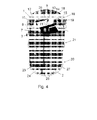
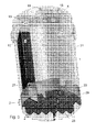
- Figure 4 shows a view of an embodiment of the purification unit seen in a three-dimensional upper/side view.
- the outer wall 1 is made transparent in order to make it possible to see the inside of the device.
- the inlet 2 is placed in the lower part 20 between the upper and lower bottoms 23 and 24. When the liquid has entered through the inlet 2 it is received in the reservoir where it stays until it is transported to the first aerated compartment 6. Normally between 5 and 15 litres of liquid is pumped to the first aerated compartment 6 every 10 to 20 minute. The liquid is pumped through the pipe 5 and the vertical part of pipe 5 is placed in compartment 14 while a horizontal part of the pipe 5 leads from the compartment 14 to the top of the first aerated compartment 6.
- Two air pipes 26 deliver air from a compressor to two diffusers each placed beneath the bio filter in the first 6 and the second 9 aerated compartments.
- the liquid After entering at the top of the first aerated compartment, the liquid passes down through the compartment and passes beneath the partition wall 12 into the second i.e. the first non-aerated compartment 7.
- the liquid rises up through the second compartment and at the top end of the second compartment the overflow pipe allows the liquid to flow into the third compartment 9.
- the liquid again in counter current with the air bubbles from the not shown diffuser flows down through the compartment.
- the liquid again passes under the partition wall 12 into the fourth compartment 10 wherefrom it passes over the edge of the overflow outlet pipe 4a into the outlet 4 and is led to a recipient.
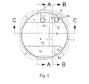
- Figure 5 shows a top view of the purification unit.
- the line A-A shows which cut can be viewed in fig. 6
- the line B-B shows which cut can be viewed in fig. 7
- the line C-C shows which cut can be viewed in fig. 8 .
- the top view of fig. 5 shows how the six upper compartments 6,7,9,10,14 and 15 are placed in relation to each other.
- the partition walls 11, 12, 13 and 18 can be welded directly to the outer wall 1 of the purification unit and to each other in order to form liquid tight compartments.
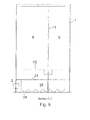
- Figure 6 shows the view seen at the cut along line A-A. From this view it is possible to see one of the bearing walls 25 from the side showing triangular openings along the lower bottom which openings in the bearing walls 25 allows the liquid which enters through the inlet 2 to diffuse into the whole volume of the reservoir provided between the upper bottom 23 and the lower bottom 24. Also in fig. 6 it is possible to see the tank 22 for phosphorous precipitation agent which is placed below the second dry compartment 15.
- Figure 7 shows the view seen at the cut along line B-B. From this view it is possible to see the length of the first dry compartment 14 which is placed below the second dry compartment 15. Also the view shows the overflow outlet pipe 4a which upper edge determines the height of liquid inside the purification unit.
- Figure 8 shows the view seen at the cut along line C-C. From this view it is possible to see the lower edge of the partition wall 12 separating the two aerated compartments 6 and 9 from the non-aerated compartments 7 and 10.
- Second non-aerated comoartment 11 Partition wall separating compartments 6/9 and compartments 7/10 12 Partition wall separating compartments 6/7 and compartments 9/10 13 Partition wall separating compartments 6 and 9 from dry compartments 14 and 15 14 First dry compartment 15 Second dry compartment 16 Compressor 17 Valve 18 Partition wall separating raising compartment and mechanics compartment 19 Inlet for phosphorous precipitation agent 20 Lower part 21 Upper part 22 Tank for phosphorous precipitation agent 23 Upper bottom 24 Lower bottom 25 Bearing walls 26 Air pipe 27 Diffuser
Landscapes
- Life Sciences & Earth Sciences (AREA)
- Chemical & Material Sciences (AREA)
- Biodiversity & Conservation Biology (AREA)
- Microbiology (AREA)
- Hydrology & Water Resources (AREA)
- Engineering & Computer Science (AREA)
- Environmental & Geological Engineering (AREA)
- Water Supply & Treatment (AREA)
- Organic Chemistry (AREA)
- Analytical Chemistry (AREA)
- Biological Treatment Of Waste Water (AREA)
Claims (12)
- Reinigungsanlage zur Reinigung von Abwasser, umfassend einen Faulbehälter und eine Reinigungseinheit, umfassend einen oberen Teil mit vier Räumen (6,7,9,10) und zwar zwei getrennte durchlüftete Räume (6,9), d.h. ein erster und ein zweiter mit Biofiltern versehener Raum und zwei getrennte nicht-durchlüftete Sedimentierungsräume (7, 10), ein erster und ein zweiter, die stromabwärts von jeweils dem ersten und zweiten durchlüfteten Raum (6, 9) angeordnet sind, wobei die Reinigungseinheit einen unteren Teil (20) aufweist, der unter einem oder beiden durchlüfteten Räumen (6,9) angeordnet ist, dadurch gekennzeichnet, dass der untere Teil (20) einen Empfangsabschnitt mit einem Einlass (2) zum Halten von sauerstoffarmen Abwasser von dem Faulbehälter umfasst, dass die Reinigungseinheit zwei Luftverteiler umfasst, die jeweils unterhalb des Biofilters im ersten (6) und zweiten (9) durchlüfteten Raum angeordnet sind, und dass der erste durchlüftete Raum (6), der größer als der zweite durchlüftete Raum (9) ist, eingerichtet ist, um 55% bis 85% Vol-% des flüssigen Volumens der gesamten Menge von Flüssigkeit in den zwei durchlüfteten Räumen (6,9) zu enthalten.
- Reinigungsanlage nach Anspruch 1, dadurch gekennzeichnet, dass der erste durchlüftete Raum (6) eingerichtet ist, um 64-70% Vol-% des flüssigen Volumens der gesamten Menge von Flüssigkeit in den zwei durchlüfteten Räumen (6, 9) zu enthalten, und der zweite durchlüftete Raum (9) eingerichtet ist, um 30-36% Vol-% des flüssigen Volumens der gesamten Menge von Flüssigkeit in den zwei durchlüfteten Räumen (6, 9) zu enthalten.
- Reinigungsanlage nach einem der vorgehenden Ansprüche, dadurch gekennzeichnet, dass die Reinigungseinheit als ein schließbares Behältnis, umfassend einen offenen Behälter mit einem entfernbaren Deckel, ausgebildet ist.
- Reinigungsanlage nach Anspruch 3, dadurch gekennzeichnet, dass der Behälter eine Außenwand (1) mit einer inneren Oberfläche umfasst, welche innere Oberfläche mit dem zu reinigen Abwasser in direktem Kontakt ist.
- Reinigungsanlage nach Anspruch 4, dadurch gekennzeichnet, dass der Behälter mit mindestens einer inneren Wand (11), die mindestens zwei vollständig getrennte Nassräume (6, 9) bildet, versehen ist.
- Reinigungsanlage nach einem der vorgehenden Ansprüche, dadurch gekennzeichnet, dass das die Außenwand (1) des oberen Teils (21) bildende Material auch die Außenwand des unteren Teils (20) bildet.
- Reinigungsanlage nach einem der vorgehenden Ansprüche, dadurch gekennzeichnet, dass der untere Teil (20) als eine offene Kammer zwischen dem Boden (23) des oberen Teils (21) und dem Boden der Reinigungseinheit (24) vorgesehen ist.
- Reinigungsanlage nach einem der vorgehenden Ansprüche, dadurch gekennzeichnet, dass der Empfangsabschnitt des unteren Teils (20) aus mehr als 75 Vol-% des unteren Teils (20) besteht.
- Reinigungsanlage nach einem der vorgehenden Ansprüche, dadurch gekennzeichnet, dass der erste durchlüftete Raum (6) mit einem Einlass für Flüssigkeit in der Nähe des Oberteils des Raums und einem Auslass in der Nähe des Bodens des Raums versehen ist, der erste Sedimentierungsraum (7) mit einem Einlass am Boden des Raums und einem Auslass in der Nähe des Oberteils des Raums versehen ist, der zweite durchlüftete Raum (9) mit einem Einlass für Flüssigkeit in der Nähe des Oberteils des Raums und einem Auslass in der Nähe des Bodens des Raums versehen ist, und der zweite Sedimentierungsraum (10) mit einem Einlass am Boden des Raums und einem Auslass (4a) in der Nähe des Oberteils des Raums versehen ist.
- Reinigungsanlage nach einem der Ansprüche 3-9, dadurch gekennzeichnet, dass der kleinste Querschnitt des entfernbaren Deckels weniger als 150 cm, normalerweise weniger als 120 cm, ist.
- Reinigungsanlage nach den Ansprüchen 1, 9 oder 10, dadurch gekennzeichnet, dass die Reinigungseinheit einen aufsteigenden Raum (14) umfasst, durch welchen die Flüssigkeit vom Empfangsabschnitt des unteren Teils (20) zu einem hohen Niveau des ersten durchlüfteten Raums (6) transportiert wird.
- Reinigungsanlage nach einem der vorgehenden Ansprüche, dadurch gekennzeichnet, dass die Anlage Mittel zur Phosphorausfällung, umfassend Rückführungsmittel (3) zum Rückführen von sauerstoffhaltigem Wasser oder sauerstoffhaltigen Verbindungen zum Vorausfällungsbehälter oder, wenn eine Phosphorausfällungseinheit vorhanden ist, entweder zum Vorausfällungsbehälter oder zur Phosphorausfällungseinheit.
Priority Applications (1)
| Application Number | Priority Date | Filing Date | Title |
|---|---|---|---|
| SI200831435T SI2209747T1 (sl) | 2007-10-08 | 2008-10-06 | Obrat za čiščenje odpadnih voda |
Applications Claiming Priority (2)
| Application Number | Priority Date | Filing Date | Title |
|---|---|---|---|
| DKPA200701448 | 2007-10-08 | ||
| PCT/EP2008/063345 WO2009047230A1 (en) | 2007-10-08 | 2008-10-06 | A plant for waste water treatment |
Publications (2)
| Publication Number | Publication Date |
|---|---|
| EP2209747A1 EP2209747A1 (de) | 2010-07-28 |
| EP2209747B1 true EP2209747B1 (de) | 2015-03-18 |
Family
ID=40104695
Family Applications (1)
| Application Number | Title | Priority Date | Filing Date |
|---|---|---|---|
| EP20080837496 Active EP2209747B1 (de) | 2007-10-08 | 2008-10-06 | Anlage zur abwasserbehandlung |
Country Status (4)
| Country | Link |
|---|---|
| EP (1) | EP2209747B1 (de) |
| PT (1) | PT2209747E (de) |
| SI (1) | SI2209747T1 (de) |
| WO (1) | WO2009047230A1 (de) |
Families Citing this family (1)
| Publication number | Priority date | Publication date | Assignee | Title |
|---|---|---|---|---|
| BE1020506A3 (nl) * | 2012-05-11 | 2013-11-05 | M H C Nv | Afvalwaterbehandelingsinstallatie. |
Family Cites Families (3)
| Publication number | Priority date | Publication date | Assignee | Title |
|---|---|---|---|---|
| US3412864A (en) | 1966-07-05 | 1968-11-26 | Okada Tamotsu | Sewage treatment plant |
| BE1014104A6 (nl) | 2001-07-06 | 2003-04-01 | Waterzuiveringstank. | |
| EP1678090B1 (de) | 2003-09-15 | 2014-12-10 | Biokube International A/S | Verfahren und anlage zur abwasserbehandlung |
-
2008
- 2008-10-06 EP EP20080837496 patent/EP2209747B1/de active Active
- 2008-10-06 SI SI200831435T patent/SI2209747T1/sl unknown
- 2008-10-06 WO PCT/EP2008/063345 patent/WO2009047230A1/en not_active Ceased
- 2008-10-06 PT PT88374962T patent/PT2209747E/pt unknown
Also Published As
| Publication number | Publication date |
|---|---|
| SI2209747T1 (sl) | 2015-08-31 |
| EP2209747A1 (de) | 2010-07-28 |
| WO2009047230A1 (en) | 2009-04-16 |
| PT2209747E (pt) | 2015-07-20 |
Similar Documents
| Publication | Publication Date | Title |
|---|---|---|
| US20090250394A1 (en) | Sewage treatment | |
| JP2013517127A (ja) | 廃水処理システム及び方法 | |
| CN105693014A (zh) | 一种污水处理系统及污水处理方法 | |
| RU2282597C1 (ru) | Способ глубокой биологической очистки сточных вод и устройство для его осуществления | |
| CN113754210A (zh) | 一种全地埋式钢筋砼结构的小型污水处理系统及处理方法 | |
| CN213388254U (zh) | 一体式生活污水处理设备 | |
| CN215975459U (zh) | 一种全地埋式钢筋砼结构的小型污水处理系统 | |
| CN212894377U (zh) | 一种生活污水处理设备 | |
| US7476321B2 (en) | Method and a plant for waste water treatment | |
| HUE009445T2 (en) | Waste water purifying device | |
| CN106007267A (zh) | 大型一体化污水处理装置及污水处理工艺 | |
| CN100519449C (zh) | 速分生物污水处理方法及系统 | |
| EP2209747B1 (de) | Anlage zur abwasserbehandlung | |
| CN213865851U (zh) | 一种生活污水处理站 | |
| JP3263267B2 (ja) | 浄化槽 | |
| CN214612082U (zh) | 一种污水处理装置 | |
| RU2736187C1 (ru) | Способ и устройство для очистки хозяйственно-бытовых сточных вод | |
| RU2279407C1 (ru) | Способ глубокой биологической очистки сточных вод и устройство для его осуществления | |
| CN210796121U (zh) | 一种集装箱式城镇污水处理设备 | |
| JP2006289153A (ja) | 汚水浄化方法及び装置 | |
| CN221701334U (zh) | 一种污水处理用连续循环流一体化生化塔 | |
| AU2006315091B2 (en) | Sewage treatment | |
| KR0119265Y1 (ko) | 유효미생물군을 이용한 합병 처리 분뇨 정화조 | |
| CN109467269B (zh) | 污水处理装置及利用其进行污水处理的方法 | |
| JP6101107B2 (ja) | エアリフトポンプを有する汚水浄化槽及び当該汚水浄化槽の運転方法 |
Legal Events
| Date | Code | Title | Description |
|---|---|---|---|
| PUAI | Public reference made under article 153(3) epc to a published international application that has entered the european phase |
Free format text: ORIGINAL CODE: 0009012 |
|
| 17P | Request for examination filed |
Effective date: 20100504 |
|
| AK | Designated contracting states |
Kind code of ref document: A1 Designated state(s): AT BE BG CH CY CZ DE DK EE ES FI FR GB GR HR HU IE IS IT LI LT LU LV MC MT NL NO PL PT RO SE SI SK TR |
|
| AX | Request for extension of the european patent |
Extension state: AL BA MK RS |
|
| 17Q | First examination report despatched |
Effective date: 20120214 |
|
| GRAP | Despatch of communication of intention to grant a patent |
Free format text: ORIGINAL CODE: EPIDOSNIGR1 |
|
| INTG | Intention to grant announced |
Effective date: 20140926 |
|
| RAP1 | Party data changed (applicant data changed or rights of an application transferred) |
Owner name: BIOKUBE INTERNATIONAL A/S |
|
| GRAS | Grant fee paid |
Free format text: ORIGINAL CODE: EPIDOSNIGR3 |
|
| GRAA | (expected) grant |
Free format text: ORIGINAL CODE: 0009210 |
|
| AK | Designated contracting states |
Kind code of ref document: B1 Designated state(s): AT BE BG CH CY CZ DE DK EE ES FI FR GB GR HR HU IE IS IT LI LT LU LV MC MT NL NO PL PT RO SE SI SK TR |
|
| AX | Request for extension of the european patent |
Extension state: AL BA MK RS |
|
| REG | Reference to a national code |
Ref country code: GB Ref legal event code: FG4D |
|
| REG | Reference to a national code |
Ref country code: CH Ref legal event code: EP |
|
| REG | Reference to a national code |
Ref country code: IE Ref legal event code: FG4D |
|
| REG | Reference to a national code |
Ref country code: AT Ref legal event code: REF Ref document number: 716440 Country of ref document: AT Kind code of ref document: T Effective date: 20150415 |
|
| REG | Reference to a national code |
Ref country code: DE Ref legal event code: R096 Ref document number: 602008037239 Country of ref document: DE Effective date: 20150430 |
|
| REG | Reference to a national code |
Ref country code: RO Ref legal event code: EPE |
|
| REG | Reference to a national code |
Ref country code: NO Ref legal event code: T2 Effective date: 20150318 Ref country code: PT Ref legal event code: SC4A Free format text: AVAILABILITY OF NATIONAL TRANSLATION Effective date: 20150612 |
|
| REG | Reference to a national code |
Ref country code: NL Ref legal event code: VDEP Effective date: 20150318 |
|
| REG | Reference to a national code |
Ref country code: NL Ref legal event code: VDEP Effective date: 20150318 |
|
| PG25 | Lapsed in a contracting state [announced via postgrant information from national office to epo] |
Ref country code: FI Free format text: LAPSE BECAUSE OF FAILURE TO SUBMIT A TRANSLATION OF THE DESCRIPTION OR TO PAY THE FEE WITHIN THE PRESCRIBED TIME-LIMIT Effective date: 20150318 Ref country code: SE Free format text: LAPSE BECAUSE OF FAILURE TO SUBMIT A TRANSLATION OF THE DESCRIPTION OR TO PAY THE FEE WITHIN THE PRESCRIBED TIME-LIMIT Effective date: 20150318 Ref country code: HR Free format text: LAPSE BECAUSE OF FAILURE TO SUBMIT A TRANSLATION OF THE DESCRIPTION OR TO PAY THE FEE WITHIN THE PRESCRIBED TIME-LIMIT Effective date: 20150318 |
|
| REG | Reference to a national code |
Ref country code: EE Ref legal event code: FG4A Ref document number: E010665 Country of ref document: EE Effective date: 20150611 |
|
| PG25 | Lapsed in a contracting state [announced via postgrant information from national office to epo] |
Ref country code: GR Free format text: LAPSE BECAUSE OF FAILURE TO SUBMIT A TRANSLATION OF THE DESCRIPTION OR TO PAY THE FEE WITHIN THE PRESCRIBED TIME-LIMIT Effective date: 20150619 |
|
| PG25 | Lapsed in a contracting state [announced via postgrant information from national office to epo] |
Ref country code: NL Free format text: LAPSE BECAUSE OF FAILURE TO SUBMIT A TRANSLATION OF THE DESCRIPTION OR TO PAY THE FEE WITHIN THE PRESCRIBED TIME-LIMIT Effective date: 20150318 |
|
| REG | Reference to a national code |
Ref country code: SK Ref legal event code: T3 Ref document number: E 18852 Country of ref document: SK |
|
| PG25 | Lapsed in a contracting state [announced via postgrant information from national office to epo] |
Ref country code: ES Free format text: LAPSE BECAUSE OF FAILURE TO SUBMIT A TRANSLATION OF THE DESCRIPTION OR TO PAY THE FEE WITHIN THE PRESCRIBED TIME-LIMIT Effective date: 20150318 Ref country code: CZ Free format text: LAPSE BECAUSE OF FAILURE TO SUBMIT A TRANSLATION OF THE DESCRIPTION OR TO PAY THE FEE WITHIN THE PRESCRIBED TIME-LIMIT Effective date: 20150318 |
|
| PG25 | Lapsed in a contracting state [announced via postgrant information from national office to epo] |
Ref country code: IS Free format text: LAPSE BECAUSE OF FAILURE TO SUBMIT A TRANSLATION OF THE DESCRIPTION OR TO PAY THE FEE WITHIN THE PRESCRIBED TIME-LIMIT Effective date: 20150718 Ref country code: PL Free format text: LAPSE BECAUSE OF FAILURE TO SUBMIT A TRANSLATION OF THE DESCRIPTION OR TO PAY THE FEE WITHIN THE PRESCRIBED TIME-LIMIT Effective date: 20150318 |
|
| REG | Reference to a national code |
Ref country code: DE Ref legal event code: R097 Ref document number: 602008037239 Country of ref document: DE |
|
| PLBE | No opposition filed within time limit |
Free format text: ORIGINAL CODE: 0009261 |
|
| STAA | Information on the status of an ep patent application or granted ep patent |
Free format text: STATUS: NO OPPOSITION FILED WITHIN TIME LIMIT |
|
| PG25 | Lapsed in a contracting state [announced via postgrant information from national office to epo] |
Ref country code: DK Free format text: LAPSE BECAUSE OF FAILURE TO SUBMIT A TRANSLATION OF THE DESCRIPTION OR TO PAY THE FEE WITHIN THE PRESCRIBED TIME-LIMIT Effective date: 20150318 |
|
| 26N | No opposition filed |
Effective date: 20151221 |
|
| REG | Reference to a national code |
Ref country code: DE Ref legal event code: R119 Ref document number: 602008037239 Country of ref document: DE |
|
| PG25 | Lapsed in a contracting state [announced via postgrant information from national office to epo] |
Ref country code: LU Free format text: LAPSE BECAUSE OF FAILURE TO SUBMIT A TRANSLATION OF THE DESCRIPTION OR TO PAY THE FEE WITHIN THE PRESCRIBED TIME-LIMIT Effective date: 20151006 |
|
| REG | Reference to a national code |
Ref country code: CH Ref legal event code: PL |
|
| GBPC | Gb: european patent ceased through non-payment of renewal fee |
Effective date: 20151006 |
|
| PG25 | Lapsed in a contracting state [announced via postgrant information from national office to epo] |
Ref country code: MC Free format text: LAPSE BECAUSE OF FAILURE TO SUBMIT A TRANSLATION OF THE DESCRIPTION OR TO PAY THE FEE WITHIN THE PRESCRIBED TIME-LIMIT Effective date: 20150318 |
|
| REG | Reference to a national code |
Ref country code: IE Ref legal event code: MM4A |
|
| PG25 | Lapsed in a contracting state [announced via postgrant information from national office to epo] |
Ref country code: LI Free format text: LAPSE BECAUSE OF NON-PAYMENT OF DUE FEES Effective date: 20151031 Ref country code: GB Free format text: LAPSE BECAUSE OF NON-PAYMENT OF DUE FEES Effective date: 20151006 Ref country code: DE Free format text: LAPSE BECAUSE OF NON-PAYMENT OF DUE FEES Effective date: 20160503 Ref country code: CH Free format text: LAPSE BECAUSE OF NON-PAYMENT OF DUE FEES Effective date: 20151031 |
|
| REG | Reference to a national code |
Ref country code: FR Ref legal event code: ST Effective date: 20160630 |
|
| PG25 | Lapsed in a contracting state [announced via postgrant information from national office to epo] |
Ref country code: FR Free format text: LAPSE BECAUSE OF NON-PAYMENT OF DUE FEES Effective date: 20151102 |
|
| PG25 | Lapsed in a contracting state [announced via postgrant information from national office to epo] |
Ref country code: IE Free format text: LAPSE BECAUSE OF NON-PAYMENT OF DUE FEES Effective date: 20151006 |
|
| REG | Reference to a national code |
Ref country code: AT Ref legal event code: UEP Ref document number: 716440 Country of ref document: AT Kind code of ref document: T Effective date: 20150318 |
|
| PG25 | Lapsed in a contracting state [announced via postgrant information from national office to epo] |
Ref country code: HU Free format text: LAPSE BECAUSE OF FAILURE TO SUBMIT A TRANSLATION OF THE DESCRIPTION OR TO PAY THE FEE WITHIN THE PRESCRIBED TIME-LIMIT; INVALID AB INITIO Effective date: 20081006 |
|
| PG25 | Lapsed in a contracting state [announced via postgrant information from national office to epo] |
Ref country code: CY Free format text: LAPSE BECAUSE OF FAILURE TO SUBMIT A TRANSLATION OF THE DESCRIPTION OR TO PAY THE FEE WITHIN THE PRESCRIBED TIME-LIMIT Effective date: 20150318 |
|
| PG25 | Lapsed in a contracting state [announced via postgrant information from national office to epo] |
Ref country code: MT Free format text: LAPSE BECAUSE OF FAILURE TO SUBMIT A TRANSLATION OF THE DESCRIPTION OR TO PAY THE FEE WITHIN THE PRESCRIBED TIME-LIMIT Effective date: 20150318 Ref country code: TR Free format text: LAPSE BECAUSE OF FAILURE TO SUBMIT A TRANSLATION OF THE DESCRIPTION OR TO PAY THE FEE WITHIN THE PRESCRIBED TIME-LIMIT Effective date: 20150318 |
|
| PGFP | Annual fee paid to national office [announced via postgrant information from national office to epo] |
Ref country code: SK Payment date: 20190312 Year of fee payment: 11 |
|
| REG | Reference to a national code |
Ref country code: EE Ref legal event code: HC1A Ref document number: E010665 Country of ref document: EE |
|
| REG | Reference to a national code |
Ref country code: SK Ref legal event code: MM4A Ref document number: E 18852 Country of ref document: SK Effective date: 20191006 |
|
| PG25 | Lapsed in a contracting state [announced via postgrant information from national office to epo] |
Ref country code: SK Free format text: LAPSE BECAUSE OF NON-PAYMENT OF DUE FEES Effective date: 20191006 |
|
| PGFP | Annual fee paid to national office [announced via postgrant information from national office to epo] |
Ref country code: RO Payment date: 20220916 Year of fee payment: 15 Ref country code: PT Payment date: 20220912 Year of fee payment: 15 Ref country code: NO Payment date: 20220912 Year of fee payment: 15 Ref country code: LT Payment date: 20220909 Year of fee payment: 15 Ref country code: EE Payment date: 20220909 Year of fee payment: 15 Ref country code: BG Payment date: 20220914 Year of fee payment: 15 |
|
| PGFP | Annual fee paid to national office [announced via postgrant information from national office to epo] |
Ref country code: LV Payment date: 20220909 Year of fee payment: 15 Ref country code: BE Payment date: 20220909 Year of fee payment: 15 |
|
| PGFP | Annual fee paid to national office [announced via postgrant information from national office to epo] |
Ref country code: IT Payment date: 20220912 Year of fee payment: 15 Ref country code: AT Payment date: 20220912 Year of fee payment: 15 |
|
| PGFP | Annual fee paid to national office [announced via postgrant information from national office to epo] |
Ref country code: SI Payment date: 20220909 Year of fee payment: 15 |
|
| REG | Reference to a national code |
Ref country code: LT Ref legal event code: MM4D Effective date: 20231006 |
|
| REG | Reference to a national code |
Ref country code: EE Ref legal event code: MM4A Ref document number: E010665 Country of ref document: EE Effective date: 20231031 |
|
| REG | Reference to a national code |
Ref country code: AT Ref legal event code: MM01 Ref document number: 716440 Country of ref document: AT Kind code of ref document: T Effective date: 20231006 |
|
| REG | Reference to a national code |
Ref country code: BE Ref legal event code: MM Effective date: 20231031 |
|
| PG25 | Lapsed in a contracting state [announced via postgrant information from national office to epo] |
Ref country code: LT Free format text: LAPSE BECAUSE OF NON-PAYMENT OF DUE FEES Effective date: 20231006 |
|
| PG25 | Lapsed in a contracting state [announced via postgrant information from national office to epo] |
Ref country code: AT Free format text: LAPSE BECAUSE OF NON-PAYMENT OF DUE FEES Effective date: 20231006 |
|
| PG25 | Lapsed in a contracting state [announced via postgrant information from national office to epo] |
Ref country code: NO Free format text: LAPSE BECAUSE OF NON-PAYMENT OF DUE FEES Effective date: 20231031 Ref country code: LT Free format text: LAPSE BECAUSE OF NON-PAYMENT OF DUE FEES Effective date: 20231006 Ref country code: EE Free format text: LAPSE BECAUSE OF NON-PAYMENT OF DUE FEES Effective date: 20231031 Ref country code: BG Free format text: LAPSE BECAUSE OF NON-PAYMENT OF DUE FEES Effective date: 20231006 Ref country code: AT Free format text: LAPSE BECAUSE OF NON-PAYMENT OF DUE FEES Effective date: 20231006 Ref country code: SI Free format text: LAPSE BECAUSE OF NON-PAYMENT OF DUE FEES Effective date: 20231007 |
|
| PG25 | Lapsed in a contracting state [announced via postgrant information from national office to epo] |
Ref country code: PT Free format text: LAPSE BECAUSE OF NON-PAYMENT OF DUE FEES Effective date: 20240408 |
|
| PG25 | Lapsed in a contracting state [announced via postgrant information from national office to epo] |
Ref country code: PT Free format text: LAPSE BECAUSE OF NON-PAYMENT OF DUE FEES Effective date: 20240408 Ref country code: LV Free format text: LAPSE BECAUSE OF NON-PAYMENT OF DUE FEES Effective date: 20231006 Ref country code: BE Free format text: LAPSE BECAUSE OF NON-PAYMENT OF DUE FEES Effective date: 20231031 |
|
| REG | Reference to a national code |
Ref country code: SI Ref legal event code: KO00 Effective date: 20240722 |
|
| PG25 | Lapsed in a contracting state [announced via postgrant information from national office to epo] |
Ref country code: RO Free format text: LAPSE BECAUSE OF NON-PAYMENT OF DUE FEES Effective date: 20231006 |
|
| PG25 | Lapsed in a contracting state [announced via postgrant information from national office to epo] |
Ref country code: IT Free format text: LAPSE BECAUSE OF NON-PAYMENT OF DUE FEES Effective date: 20231006 |
|
| PG25 | Lapsed in a contracting state [announced via postgrant information from national office to epo] |
Ref country code: IT Free format text: LAPSE BECAUSE OF NON-PAYMENT OF DUE FEES Effective date: 20231006 |