EP2209218A2 - Drahtlose Anschlusseinrichtung für Dienstleistungsbereiche - Google Patents
Drahtlose Anschlusseinrichtung für Dienstleistungsbereiche Download PDFInfo
- Publication number
- EP2209218A2 EP2209218A2 EP10150711A EP10150711A EP2209218A2 EP 2209218 A2 EP2209218 A2 EP 2209218A2 EP 10150711 A EP10150711 A EP 10150711A EP 10150711 A EP10150711 A EP 10150711A EP 2209218 A2 EP2209218 A2 EP 2209218A2
- Authority
- EP
- European Patent Office
- Prior art keywords
- leaky
- furniture
- cable
- wave cable
- wave
- Prior art date
- Legal status (The legal status is an assumption and is not a legal conclusion. Google has not performed a legal analysis and makes no representation as to the accuracy of the status listed.)
- Granted
Links
Images




Classifications
-
- H—ELECTRICITY
- H04—ELECTRIC COMMUNICATION TECHNIQUE
- H04B—TRANSMISSION
- H04B5/00—Near-field transmission systems, e.g. inductive or capacitive transmission systems
- H04B5/20—Near-field transmission systems, e.g. inductive or capacitive transmission systems characterised by the transmission technique; characterised by the transmission medium
- H04B5/28—Near-field transmission systems, e.g. inductive or capacitive transmission systems characterised by the transmission technique; characterised by the transmission medium using the near field of leaky cables, e.g. of leaky coaxial cables
Definitions
- the invention relates to a wireless connection device according to the preamble of claim 1 and a furniture equipped therewith according to the preamble of the independent claim.
- the invention relates to a wireless connection device for service areas, such as e.g. Bank branches to provide electronic or data processing equipment, such as Personal computer, printer and the like to connect wirelessly to a data network, being used to set up the equipment furniture in the form of switch furniture, desks and the like.
- Wireless connection devices in the form of wireless devices for wireless local area networks (WLANs) are known in which at least one radio base station connected to the network, which is also referred to as a wireless access node (WLAN access node), is installed in the room ,
- the at least one radio base station can be used as a device for wireless connection to the data network of such data processing devices that have corresponding wireless radio modules.
- a standard for example according to IEEE-802.11, is usually used. At present, data transfer rates of 54 Mbit / s can already be realized.
- the radio base stations serve as central access nodes, they are usually installed in exposed areas in the room in order to achieve the widest coverage coverage possible.
- connection device which is suitable for a secure and efficient wireless connection of at least one data-processing device to a data network.
- the connection device should be suitable for a wireless connection of devices, especially in such service areas that are frequented by customers, such as bank branches, information desks, self-service areas and the like.
- a wireless connection device which has at least one leaky-wave cable, wherein the leaky-wave cable is integrated in a piece of furniture which is provided for at least one electronic or data-processing device.
- the leaky-wave cable can be integrated into a storage or working surface provided on the furniture.
- the leaky-wave cable can also be routed in a cable channel provided in the furniture.
- a wireless or wireless connection of at least one data-processing device is provided on the furniture itself.
- the leaky-wave cable allows a targeted, preferably linear, expression of a radio field area in the immediate vicinity of the piece of furniture, in particular in the area of the storage area or work surface.
- the propagation of the radio field area is on the for the devices limited position ranges.
- Low-power radio transmitters can be used.
- the nature of the radio coverage is based on the furniture itself and is thus independent of the circumstances of the premises used. This has particular advantages in a possible rearrangement of the furniture or even in a move to other premises.
- the furniture provided with the connection device is a modular system that can be easily modified and expanded.
- the leaky-wave cable can be optimized with regard to its arrangement and / or configuration, in particular with regard to the dimensioning of its slots, to a radio link restricted to the near range. For example, this can be achieved by designing the slot openings and / or their distances. In this context, it is advantageous if the arrangement, dimensioning and / or configuration of the slots is aligned with the creation of a plurality of small radio zones forming on the shelf of the furniture, which have an extension of only a few centimeters, about 25 cm.
- a terminal unit may be provided to connect the leaky-wave cable to the data network.
- the connection unit is also suitable for connecting a power supply cable routed in the furniture to a power supply network.
- the power supply can also be done wirelessly via the leaky-wave cable itself or can be done via an additionally misplaced cable in the form of an induction conductor or another leaky-wave cable.
- a termination element is preferably provided which has a defined characteristic impedance in order to complete the leakage wave cable without reflection.
- the furniture according to the invention preferably has a storage or. Work surface for at least one data-processing device on, with the leaky-wave cable is integrated into the shelf. Additionally or alternatively, a cable channel may be provided in the furniture, in which the leaky-wave cable is laid and possibly also a power supply cable is laid.
- the furniture according to the invention can also be provided with at least one mechanically formed connecting element with which one of the data-processing devices can be connected directly via a corresponding connecting element or via a connecting device in order to optimize this device on the storage surface of the furniture for wireless data transmission via the leaky-wave cable to position.
- the connecting elements are assembled or plugged together.
- the connecting elements can be designed for the production of an irreversible plug-in connection, so that the respective data-processing device engages in the optimum position and remains there.
- the connecting device with the connecting elements provided thereon can also be designed such that it has a locking device in the plane of the parking brake.
- connection produces, in particular produces an eccentric connection, so that the device can be moved to a limited extent, for example, to be positioned for operation by a customer.
- the connecting elements provided on the furniture are preferably arranged such that the respectively positioned device and in particular a radio module integrated therein are located in the vicinity of one of the slots of the leaky-wave cable.
- the furniture according to the invention can be designed, for example, as office furniture, in particular as a desk, or as switch furniture, in particular as a switch counter.
- the solution presented here is suitable i.a. for use in bank branches and the like and will be referred to in this context also briefly below as a "wireless branch".
- a schematic representation of a wireless connection device 100 which enables the wireless connection of a plurality of electronic, in particular data processing, devices 210, 220, 230 and 240 to a data network NM.
- the connection device 100 has, in particular, a leaky-wave cable 120 which is housed in a piece of furniture (see Fig. 3 ) is integrated.
- the leaky-wave cable 120 is along with a power supply cable 130 housed in a cable channel 110 which is integrated in the furniture.
- the power supply cable 130 is connected to a power supply network, not shown, and provides a plurality of connection points, which also have mechanical fasteners 252 *, a power supply of the connected devices ready, here, for example, the devices 210 and 240, ready.
- the actual data transmission through a wireless radio link is provided by the leaky-wave cable 120, which has slots 121 at regular intervals. Via the slots 121, the expression of smallest radio zones with an extension of e.g. 25cm, in order to provide a sufficient and secure wireless connection by radio transmission RF for the data processing devices 210 to 240 in the immediate vicinity of the furniture, but at least in the vicinity of the cable channel 110.
- the devices 210 to 240 shown here can be, for example, the following:
- the device 210 is intended here to be a personal computer (PC) or a data terminal, which is set up and set up for customer service in a bank branch.
- the device 220 is, for example, a peripheral device in the form of a printer, and the device 230 is a peripheral device in the form of a scanner.
- the device 240 is a special peripheral device, namely an automatic cash vault, which is also wirelessly connected to the data network NW via the leaky-wave cable 120.
- All devices can thus use the respective radio link RF data with the network NW or possibly directly with each other change.
- the bank customer can log in via the PC or the data terminal 210 in the data network NW under his user account and cause, for example, the process "print account statement" to receive an account statement via the printer 220.
- Another process may involve, for example, the payment of cash, so that the customer finally gets the desired cash through the automatic cash safe 240.
- connecting elements 252 * are provided on the furniture, which cooperate with corresponding connecting elements 215, which are located on the devices themselves.
- the example of the device 210 which represents a PC, it can be seen that this via the connecting device 250 and corresponding connecting elements 251, 252, etc. (see also Fig. 4 and 5 ) is positioned so that a radio module 212 integrated in the PC 210 optimally aligns with the closest slot 121 of the leaky-wave cable 120.
- Fig. 1 Illustratively, along the leaky-wave cable 110 at the respective spaced slots 121, small radio coverage areas are formed for each device located near the slot 121.
- an optimal radiation range with a defined limitation to, for example, 25 cm can be achieved.
- the radio field occurs only at the slot openings and has a relatively low scattering (see also Fig. 2 ). This ensures that the radio coverage does not go beyond the necessary range is extended and accessible for unauthorized access from the outside.
- the connector device 100 provided with a leaky-wave cable 120 and integrated in a piece of furniture is particularly suitable for use in service areas or centers, e.g. in customer or counter areas of banks.
- the wireless connection of several devices to the local data network allows the fast construction and possibly the rearrangement of the arrangement.
- the integration of the leaky-wave cable 120 into the intended furniture ensures an optimized radio connection to the working area. This applies both to the quality (transmission rate, security, etc.) as well as to the quantity (data transmission rate, energy efficiency, etc.) of the radio transmission.
- the radio transmission takes place in accordance with a WLAN standard in the 2.4 GHz range.
- the leaky-wave cable itself has at one end a connection point A, which is located at or in a connection unit 125, which in turn establishes the connection to the data network NW.
- This connection unit 125 may, for example, be a so-called access point, i. to a wireless modem or router with radio part that includes a connection option for the leak wave cable 110.
- the WLAN modem is connected to the data network NW via an Ethernet connection.
- connection unit 125 thus forms, in terms of message transmission, the link between the data network NW and the leaky-wave cable 110.
- a termination element 20 At the other end of the Leak wave cable is a termination element 20 in the form of a characteristic impedance, which terminates the leak wave cable without reflection.
- connection unit even for the energy or power supply, for example, to connect the power supply cable 130 with the power supply network, not shown here.
- the terminal unit could include a device (RF generator) that energizes the leaky-wave cable 110 for wireless energy transmission.
- RF generator RF generator
- the leaky-wave cable 120 serves exclusively for wireless data transmission.
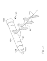
- the Fig. 2 shows a schematic view of the structural design of the leaky-wave cable 120 and the radio waves that form out therefrom.
- the leaky-wave cable 120 basically consists of an inner conductor 120a, an outer conductor 120c and a dielectric 120b therebetween.
- the structure of the leaky-wave cable corresponds to the construction of a co-axial cable, with the difference that slots 121 are provided in the outer conductor 120c at predefined intervals.
- a wave propagation FR * for a radio connection RF is generated through the slot openings Fig. 2 is shown by way of example.
- the arrangement of the slots 121 and / or their dimensioning can optimize the wave propagation to the respectively provided frequency range (here 2.4 GHz). This applies in particular to the extent of the respective radio zone, so that it can be achieved that only in the vicinity of, for example, 25cm spreads a sufficiently large radio field.
- the same also applies in the receive direction, with the radio signals received via the leaky-wave cable 120 emanating from corresponding radio modules of the respectively set up devices (see "212" in FIG Fig. 1 ).
- the radio modules can also be designed as external radio modules, for example in the form of USB sticks, which are connected to PCs or laptops and the like.
- the Fig. 3 shows in views a), b) and c) an inventive furniture 300 in the form of a desk, which has a storage area 310 for devices, here for example for the PC 210.
- the wireless connection device 110 including the leak wave cable is integrated.
- the devices (PC 210) located on the storage or working surface 310 and possibly also other devices located in the immediate vicinity (automatic cash safe 240) can be connected wirelessly to the data network.
- the connection elements described in more detail below it is ensured that at least the devices located on the storage surface 310 are in an optimal position to the leaky-wave cable.
- the person P here a bank customer, can by a rotatable embodiment of the connecting device 250, as Exzenter connection acts and is arranged on the furniture in the cable channel linearly displaceable, the position of the respective device still change something.
- the device itself however, remains attached to the intended place. Removal or theft of the device is not possible or only by force.
- the Fig. 4 and 5 illustrate in various representations proposed for this connection technology.
- the data processing device 210 which is here a so-called. All-In-One PC, in various views, wherein on the lower side of the housing 210, a connection part 251 * are provided to the connecting device 250, which has an in-plane connection for flexible but accurate positioning of the device 210 in the immediate vicinity of the leaky-wave cable out forms (see also Fig. 3 ).
- the connecting device 250 shown here has a platform element 255 and connecting parts or elements arranged thereon, which are inserted into one another for producing a rotatable connection, wherein the parts or elements are designed such that an eccentric connection is produced, which is a horizontal Pivoting or rotating and moving the device 210 on the work surface within a predefined range allows (see also Fig. 5 ).
- an eccentric connection is produced, which is a horizontal Pivoting or rotating and moving the device 210 on the work surface within a predefined range allows (see also Fig. 5 ).
- the user or customer can position the device 210 to a certain extent without the device being able to be removed too far from the leaky-wave cable.
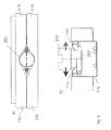
- the Fig. 6 shows in two views a) and b) the embodiment of a cable channel 110 according to the invention, which completely in the work surface or shelf 310 of the Furniture is integrated.
- the cable channel 110 is located at predefined intervals each have a connection or connection element 252 *, which is optionally along the cable channel via a corresponding guide (guide rails or - grooves) slidably disposed.
- the cable channel 110 has at its upper ends in each case two opposite elastic plastic elements, such as rubber lips 111, on.
- the connection element 252 * in turn is at least connected to the power supply cable (see also Fig. 1 ), so that the respective device positioned via connection point 252 * can be supplied with power.
- the power supply may be a conventional AC voltage of 220V and 50Hz, but it may be a low voltage DC power supply or the like. How the particular Fig. 6b ), the cable channel 110 is completely integrated in the working surface 310 of the piece of furniture together with the leaky-shaft cable laid therein as well as further connection and supply elements provided.
- Fig. 7a ) and b) show in further views the fixed in or on the cable channel connecting device 250 in the assembled state and illustrate its operation. Since the connecting device 250 is formed as an eccentric, the respective device can be pivoted in the horizontal plane about a fulcrum which mounts on the connecting element 252 *. Thus, the device can assume different positions within a defined range (see also Fig. 4a ) and 5a )), however, the device is always in the immediate vicinity of the leaky-wave cable and thus always a secure and reliable radio connection remains.
- the invention presented here is suitable, inter alia, for use in switch areas such as those found, for example, in bank or post office branches.
- a very flexible infrastructure for a wireless data transmission for devices or components in the switch area can be realized.
- the leaky-wave cable integrated in the furniture e.g., switchboard
- the leaky-wave cable can also be provided for supplying energy to individual components.
- peripheral devices such as automatic cash vaults, can be integrated.
- the arrangement, dimensioning and / or configuration of the leaky-wave cable restricts the radio range to the narrower surroundings of the furniture.
- the invention is particularly suitable for use in self-service areas of banks and the like and can be used to perform the following functions: deposit or pay-out and further recycling of banknotes, coin processing (input, output, counting), access to passbook and other account services, advisory services, such as for example, contracting, information services, including customer identification via card and / or signature, issuing of transfer forms, checks and like.
- the use of a leak wave cable creates a very clearly defined and directional WLAN connection, which is protected against external attacks.
- a leaky-wave cable it is also possible to provide a power line or busbar for supplying energy.
- the solution according to the invention also makes it possible to connect a plurality of furniture to one another, wherein the wireless connection devices can be designed, for example, as a data hub.
- the defined characteristics of the radio field areas not only reduce the energy required, but also reduce the EMC problem.
- the mechanical connection between the devices and the furniture itself preferably takes place via a connecting device in the form of a turntable or the like.
- the connecting elements are preferably designed as non-detachable plug-in connections. This allows the customer to move or swivel the device in a certain range, but the device itself can not be removed from the workplace.
- the invention represents a highly integrated and very flexible and comfortable infrastructure.
Landscapes
- Engineering & Computer Science (AREA)
- Computer Networks & Wireless Communication (AREA)
- Signal Processing (AREA)
- Near-Field Transmission Systems (AREA)
- Waveguide Aerials (AREA)
Abstract
Description
- Die Erfindung betrifft eine drahtlose Anschlusseinrichtung nach dem Oberbegriff des Anspruchs 1 und ein damit ausgestattetes Möbel nach dem Oberbegriff des nebengeordneten Anspruchs. Insbesondere betrifft die Erfindung eine drahtlose Anschlusseinrichtung für Dienstleistungsbereiche, wie z.B. Bankfilialen, um dort elektronische bzw. datenverarbeitende Geräte, wie z.B. Personal Computer, Drucker und dergleichen, kabellos an ein Datennetzwerk anzuschließen, wobei zum Aufstellen der Geräte Möbel in Gestalt von Schaltermöbeln, Schreibtischen und dergleichen genutzt werden.
- Bekannt sind drahtlose Anschlusseinrichtungen in Gestalt von Funkvorrichtungen für sog. drahtlose lokale Netzwerke (WLAN: Wireless Local Access Networks), bei denen mindestens eine mit dem Netzwerk verbundene Funkbasisstation, die auch als drahtloser Zugangsknoten (WLAN Access Node) bezeichnet wird, im Raum installiert ist. Die mindestens eine Funkbasisstation kann als Einrichtung zum drahtlosen Anschluss an das Datennetzwerk von solchen datenverarbeitenden Geräten genutzt werden, die über entsprechende WLAN-Funkmodule verfügen. Zur Funkübertragung wird üblicherweise ein Standard, z.B. nach IEEE-802.11, verwendet. Damit können derzeit bereits Datenübertragungsraten von 54 Mbit/s realisiert werden. Da die Funkbasisstationen als zentrale Zugangsknoten dienen, werden sie üblicherweise an exponierten Stellen im Raum installiert, um eine möglichst flächendeckende Funkversorgung zu erreichen. Das hat allerdings den Nachteil, dass die Funkbasisstationen ggf. ein größeres über den eigentlichen Raumbereich hinausgehendes Funkfeld ausprägen. Somit besteht die Gefahr, dass von Außen durch Einsatz fremder drahtloser Geräte unerlaubte Zugriffe auf das Datennetzwerk versucht werden können. Als Schutzmaßnahmen werden üblicherweise Sicherheitskodierungen (z.B. WPA) eingesetzt, die aber auch keine vollkommende Sicherung bieten können. Zudem bedeutet der Einsatz von mehreren Funkbasisstationen einen gewissen Installationsaufwand, insbesondere dann, wenn mehrere Räumlichkeiten versorgt werden sollen.
- In der
DE 20 2005 006 060 U1 wird zur drahtlosen Funkversorgung von mehreren Räumlichkeiten eine Anordnung mit Leckwellenkabeln bzw. Leckwellenleitern vorgeschlagen. Dabei handelt es sich um speziell ausgebildete und mit Schlitzen versehene Kabel, die anstelle von Rundstrahlantennen eingesetzt werden können, wobei aber eine linienförmige Ausreitungscharakteristik ausgeprägt wird. In der genannten Schrift wird die WLAN-Versorgung von Fluren oder flurähnlichen Räumlichkeiten beschrieben und vorgeschlagen, im Gebäude mehrere Leckwellenkabel an den Decken zu installieren. Da die Installation sich an den Gegebenheiten des Gebäudes und der Räumlichkeiten orientiert, kann sie jedoch sehr aufwendig sein. Zudem müssen die an den Decken verlegten Leckwellenkabel mit einer ausreichenden Signalstärke betrieben werden, um sicherzustellen, dass alle Raumbereiche funktechnisch gut versorgt sind. - Es ist daher Aufgabe der vorliegenden Erfindung, eine drahtlose Anschlusseinrichtung der eingangs genannten Art so zu verbessern, dass die genannten Nachteile überwunden werden. Insbesondere soll eine Anschlusseinrichtung vorgeschlagen werden, die für eine sichere und effiziente drahtlose Anbindung mindestens eines datenverarbeitenden Gerätes an ein Datennetzwerk geeignet ist. Die Anschlusseinrichtung soll für eine kabellose Anbindung von Geräten insbesondere in solchen Dienstleistungsbereichen geeignet sein, die von Kunden frequentiert werden, wie zum Beispiel in Bankfilialen, an Informationsschaltern, in Selbstbedienungsbereichen und dergleichen.
- Gelöst wird die Aufgabe durch eine drahtlose Anschlusseinrichtung mit den Merkmalen des Anspruchs 1.
- Demnach wird eine drahtlose Anschlusseinrichtung vorgeschlagen, die mindestens ein Leckwellenkabel aufweist, wobei das Leckwellenkabel in einem Möbel integriert ist, das für zumindest ein elektronisches bzw. datenverarbeitendes Gerät bereitgestellt ist. Insbesondere kann das Leckwellenkabel in eine an dem Möbel vorgesehene Abstell- bzw. Arbeitsfläche integriert sein. Auch kann das Leckwellenkabel in einem in dem Möbel vorgesehenen Kabelkanal verlegt sein.
- Durch die erfindungsgemäße Merkmalskombination wird an dem Möbel selbst eine drahtlose bzw. kabellose Anbindung von mindestens einem datenverarbeitenden Gerät vorgesehen. Das Leckwellenkabel ermöglicht dabei eine gezielte, vorzugsweise linienförmige, Ausprägung eines Funkfeldbereichs in unmittelbarer Umgebung des Möbels, insbesondere im Bereich der Abstellfläche bzw. Arbeitsfläche. Somit ist die Ausbreitung des Funkfeldbereichs auf die für die Geräte vorgesehenen Positionsbereiche beschränkt. Es können leistungsschwächere Funksendeverstärker eingesetzt werden. Zudem besteht quasi keine Möglichkeit, unerlaubt von Außen auf die Funkversorgung und Datenanbindung zuzugreifen. Weiterhin orientiert sich die Ausprägung der Funkversorgung an den Möbeln selbst und ist somit unabhängig von den Gegebenheiten der genutzten Räumlichkeiten. Das hat insbesondere Vorteile bei einer evtl. Umordung der Möbel oder gar bei einem Umzug in andere Räumlichkeiten. Die mit der Anschlusseinrichtung versehenen Möbel stellen ein modulares System dar, das leicht modifiziert und erweitert werden kann.
- Um eine definierte Ausbreitung der Funkwellen zu erreichen, kann das Leckwellenkabel hinsichtlich seiner Anordnung und/oder Ausgestaltung, insbesondere hinsichtlich der Dimensionierung seiner Schlitze, auf eine den Nahbereich beschränkte Funkverbindung hin optimiert werden. Beispielsweise kann dies durch Gestaltung der Schlitzöffnungen und/oder ihrer Abstände erreicht werden. In diesem Zusammenhang ist es vorteilhaft, wenn die Anordnung, Dimensionierung und/oder Ausgestaltung der Schlitze auf die Schaffung mehrerer sich auf der Abstellfläche des Möbels ausbildender kleinster Funkzonen ausgerichtet ist, die eine Ausdehnung von nur einigen Zentimetern, etwa 25 cm, aufweisen.
- An einem ersten Ende des Leckwellenkabels kann eine Anschlusseinheit vorgesehen sein, um das Leckwellenkabel mit dem Datennetzwerk zu verbinden. In diesem Zusammenhang kann auch vorgesehen sein, dass die Anschlusseinheit ebenfalls geeignet ist, ein in dem Möbel verlegtes Stromversorgungskabel mit einem Stromversorgungsnetz zu verbinden. Alternativ zum Stromversorgungskabel kann die Stromversorgung auch drahtlos über das Leckwellenkabel selbst erfolgen oder kann über ein zusätzlich verlegtes Kabel in Form eines Induktionsleiters oder eines weiteren Leckwellenkabels erfolgen.
- An einem zweiten Ende des Leckwellenkabels ist vorzugsweise ein Abschlusselement vorgesehen, das einen definierten Wellenwiderstand aufweist, um das Leckwellenkabels reflektionsfrei abzuschließen.
- Das erfindungsgemäße Möbel weist vorzugsweise eine Abstell-bzw. Arbeitsfläche für mindestens ein datenverarbeitendes Gerät auf, wobei das Leckwellenkabel in die Abstellfläche integriert ist. Zusätzlich oder auch alternativ dazu kann in dem Möbel ein Kabelkanal vorgesehen sein, in welchem das Leckwellenkabel verlegt und ggf. noch ein Stromversorgungskabel verlegt ist.
- Das erfindungsgemäße Möbel kann auch mit mindestens einem mechanisch ausgebildeten Verbindungselement versehen sein, mit dem jeweils eines der datenverarbeitenden Geräte direkt über ein entsprechendes Verbindungselement oder über eine Verbindungsvorrichtung verbindbar ist, um dieses Gerät auf der Abstellfläche des Möbels für eine über das Leckwellenkabel geführte drahtlose Datenübertragung optimal zu positionieren. Vorzugsweise sind die Verbindungselemente zusammenfügbar bzw. zusammensteckbar ausgeführt. Die Verbindungselemente können für die Herstellung einer irreversiblen Steckverbindung ausgeführt sein, so dass das jeweilige datenverarbeitende Gerät in der optimalen Position einrastet und dort verbleibt. Die Verbindungsvorrichtung mit den daran vorgesehenen Verbindungselementen kann auch so ausgestaltet sein, dass sie eine in der Ebene der Abstell- bzw. Arbeitsfläche drehbare Verbindung herstellt, insbesondere eine Exzenter-Verbindung herstellt, so dass das Gerät in einem beschränkten Umfang bewegt werden kann, um z.B. für die Bedienung durch einen Kunden positioniert zu werden. Die an dem Möbel vorgesehenen Verbindungselemente sind vorzugsweise so angeordnet, dass das jeweils positionierte Gerät und insbesondere ein darin integrierte Funkmodul sich in der Nähe eines der Schlitze des Leckwellenkabels befinden.
- Das erfindungsgemäße Möbel kann beispielsweise als Büromöbel, insbesondere als Schreibtisch, oder als Schaltermöbel, insbesondere als Schaltertresen, ausgebildet sein. Die hier vorgestellte Lösung eignet sich u.a. zum Einsatz in Bankfilialen und dergleichen und soll in diesem Zusammenhang nachfolgend auch kurz als "kabellose Filiale" bezeichnet werden.
- Die genannten Vorteile und weitere ergeben sich auch aus den Unteransprüchen.
- Nachfolgend wird die Erfindung im Detail anhand von Ausführungsbeispielen beschrieben, wobei auf die beiliegenden Zeichnungen Bezug genommen wird, die folgende schematische Darstellungen wiedergeben:
- Fig. 1
- zeigt die Grundstruktur einer drahtlosen Anschlusseinrichtung mit Leckwellenkabel, das in einem Kabelkanal eines Möbels integriert ist.
- Fig. 2
- zeigt in einem Detail den Aufbau eines Leckwellenkabels und veranschaulicht die sich daran ausbildenden elektromagnetischen Funkwellen.
- Fig. 3 a)-c)
- zeigen in verschiedenen Ansichten ein erfindungsgemäßes Möbel mit darauf bzw. daran positionierten datenverarbeitenden Geräten.
- Fig. 4 a)-b)
- zeigen in verschiedenen Ansichten ein datenverarbeitendes Gerät mit einer daran vorgesehenen Verbindungsvorrichtung.
- Fig. 5 a)-b)
- zeigen in weiteren Ansichten das datenverarbeitende Gerät mit der erfindungsgemäßen Verbindungsvorrichtung.
- Fig. 6 a)-b)
- zeigen in verschiedenen Ansichten den Aufbau eines Kabelkanals mit darin integriertem Verbindungselement.
- Fig. 7 a)-b)
- zeigen in verschiedenen Ansichten die Funktion und Aufbau einer hergestellten Exzenter-Verbindung.
- In
Fig. 1 ist in schematischer Darstellung eine erfindungsgemäße drahtlose Anschlusseinrichtung 100 dargestellt, die den drahtlosen Anschluss von mehreren elektronischen, insbesondere datenverarbeitenden, Geräten 210, 220, 230 und 240 an ein Datennetzwerk NM ermöglicht. Die Anschlusseinrichtung 100 weist dazu insbesondere ein Leckwellenkabel 120 auf, das in einem Möbel (sieheFig. 3 ) integriert ist. In dem hier dargestellten Beispiel ist das Leckwellenkabel 120 zusammen mit einem Stromversorgungskabel 130 in einem Kabelkanal 110 aufgenommen, der in dem Möbel integriert ist. Das Stromversorgungskabel 130 ist mit einem nicht dargestellten Stromversorgungsnetz verbunden und stellt über mehrere Anschlusspunkte, die auch mechanische Verbindungselemente 252* aufweisen, eine Stromversorgung der angeschlossenen Geräte bereit, hier z.B. der Geräte 210 und 240, bereit. - Zur eigentlichen Datenübertragung durch eine drahtlose Funkanbindung dient das Leckwellenkabel 120, welches in regelmäßigen Abständen Schlitze 121 aufweist. Über die Schlitze 121 erfolgt die Ausprägung von kleinsten Funkzonen mit einer Ausdehnung von z.B. 25cm, um im nahen Umfeld des Möbels, zumindest aber in der Nähe des Kabelkanals 110, eine ausreichende und sichere drahtlose Anbindung durch Funkübertragung RF für die datenverarbeitenden Geräte 210 bis 240 bereitzustellen.
- Die hier dargestellten Geräte 210 bis 240 können beispielsweise folgende sein:
- Das Gerät 210 soll hier ein Personal Computer (PC) bzw. ein Datenterminal sein, das für den Kundenservice in einer Bankfiliale eingerichtet und aufgestellt ist. Bei dem Gerät 220 handelt es sich beispielsweise um ein Peripheriegerät in Gestalt eines Druckers und bei dem Gerät 230 um ein Peripheriegerät in Form eines Scanners. Das Gerät 240 stellt ein spezielles Peripheriegerät dar, nämlich einen automatischen Kassentresor, der ebenfalls drahtlos über das Leckwellenkabel 120 mit dem Datennetzwerk NW verbunden ist.
- Alle Geräte können somit über die jeweilige Funkverbindung RF Daten mit dem Netzwerk NW oder ggf. auch direkt untereinander austauschen. In dem hier beschriebenen Anwendungsbeispiel einer Bankfiliale kann der Bankkunde sich über den PC bzw. das Datenterminal 210 in das Datennetzwerk NW unter seinem Nutzerkonto einloggen und beispielsweise den Vorgang "Kontoauszug drucken" veranlassen, um über den Drucker 220 einen Kontoauszug zu erhalten. Ein anderer Vorgang kann z.B. die Auszahlung von Bargeld betreffen, so dass der Kunde schließlich über den automatischen Kassentresor 240 das gewünschte Bargeld ausgehändigt bekommt.
- Um für eine funktechnisch optimale Positionierung der Geräte zu sorgen, sind an den Möbel Verbindungselemente 252* vorgesehen, die mit entsprechenden Verbindungselementen 215 zusammenwirken, welche sich an den Geräten selbst befinden. Am Beispiel des Gerätes 210, das einen PC darstellt, ist zu erkennen, dass dieser über die Verbindungsvorrichtung 250 und entsprechende Verbindungselemente 251, 252 usw. (siehe auch
Fig. 4 und5 ) so positioniert ist, dass ein in dem PC 210 integriertes Funkmodul 212 optimal zum nächstliegenden Schlitz 121 des Leckwellenkabels 120 hin ausgerichtet ist. - Wie anhand der
Fig. 1 veranschaulichend dargestellt ist, werden entlang des Leckwellenkabels 110 an den jeweiligen beabstandeten Schlitzen 121 kleine Funkversorgungsbereiche für das jeweils in der Nähe des Schlitzes 121 befindliche Gerät ausgebildet. Durch Anpassung der eingespeisten Sendeleistung, der Anordnung und/oder der Dimensionierung des Leckwellenkabels kann ein optimaler Abstrahlungsbereich mit definierter Begrenzung auf beispielsweise 25cm erreicht werden. Das Funkfeld tritt jeweils nur an den Schlitzöffnungen auf und hat eine relativ geringe Streuung (s. auchFig. 2 ). Somit ist sichergestellt, dass die Funkversorgung nicht über den notwendigen Bereich hinaus ausgedehnt und zugänglich für unerlaubte Zugriffen von außen ist. - Die hier vorgeschlagene mit einem Leckwellenkabel 120 versehene und in einem Möbel integrierte Anschlusseinrichtung 100 eignet sich besonders zum Einsatz in Dienstleistungsbereichen bzw. -zentren, wie z.B. in Kunden- bzw. Schalterbereichen von Banken. Die drahtlose Anbindung von mehreren Geräten an das dortige Datennetzwerk ermöglicht den schnellen Aufbau und ggf. die Umordnung der Anordnung. Durch die Integration des Leckwellenkabels 120 in die vorgesehenen Möbel ist eine auf den Arbeitsbereich hin optimierte Funkanbindung gewährleistet. Das gilt sowohl hinsichtlich der Qualität (Übertragungsrate, Sicherheit usw.) wie auch hinsichtlich der Quantität (Datenübertragungsrate, Energieeffizienz usw.) der Funkübertragung.
- In dem hier dargestellten Beispiel erfolgt die Funkübertragung entsprechend einem WLAN-Standard im 2,4 GHz Bereich. Dadurch sind hohe Übertragungsraten erzielbar. Das Leckwellenkabel selbst weist an einem Ende einen Anschlusspunkt A auf, der sich an oder in einer Anschlusseinheit 125 befindet, welche wiederum die Verbindung zum Datennetzwerk NW herstellt. Bei dieser Anschlusseinheit 125 kann es sich beispielsweise um einen sog. Access Point handeln, d.h. um ein WLAN-Modem bzw. -Router mit Funkteil, das eine Anschlussmöglichkeit für das Leckwellenkabel 110 enthält. Das WLAN-Modem ist auf der anderen Seite über einen Ethernet-Anschluss mit dem Datennetzwerk NW verbunden.
- Die Anschlusseinheit 125 bildet also hinsichtlich der Nachrichtenübertragung das Bindeglied zwischen Datennetzwerk NW und Leckwellenkabel 110. An dem anderen Ende des Leckwellenkabels befindet sich ein Abschlusselement 20 in Form eines Wellenwiderstandes, der das Leckwellenkabel reflektionsfrei abschließt.
- Es ist denkbar, die Anschlusseinheit auch noch für die Energie- bzw. Stromversorgung zu erweitern, um beispielsweise das Stromversorgungskabel 130 mit dem hier nicht dargestellten Stromversorgungsnetz zu verbinden. Auch könnte die Anschlusseinheit eine Vorrichtung (HF-Generator) aufweisen, die das Leckwellenkabel 110 für eine drahtlose Energie-Übertragung anregt. Gleiches gilt für ein zusätzliches Leckwellenkabel oder für einen Induktionsleiter. In dem hier gezeigten Beispiel dient das Leckwellenkabel 120 ausschließlich der drahtlosen Datenübertragung.
- Die
Fig. 2 zeigt in einer schematischen Ansicht den strukturellen Aufbau des Leckwellenkabels 120 sowie die sich daran ausprägenden Funkwellen. Das Leckwellenkabel 120 besteht im Wesentlichen aus einem Innenleiter 120a, einem Außenleiter 120c und einem dazwischen befindlichen Dielektrikum 120b. Somit entspricht der Aufbau des Leckwellenkabels dem Aufbau eines Koexialkabels mit dem Unterschied, dass im Außenleiter 120c in vordefinierten Abständen Schlitze 121 vorgesehen sind. Durch die Schlitzöffnungen wird bei Anschluss des Leckwellenkabels 120 an ein Funksendeteil eine Wellenausbreitung FR* für eine Funkverbindung RF erzeugt, die hier inFig. 2 beispielhaft dargestellt ist. Neben der Einstellung der eingespeisten Signalstärke kann durch die Anordnung der Schlitze 121 und/oder deren Dimensionierung die Wellenausbreitung auf den jeweils vorgesehenen Frequenzbereich hin (hier 2,4 GHz) optimiert werden. Das gilt insbesondere für die Ausdehnung der jeweiligen Funkzone, so dass erreicht werden kann, dass sich nur im Nahbereich von beispielsweise 25cm ein ausreichend großes Funkfeld ausbreitet. Dasselbe gilt auch in Empfangsrichtung, wobei die über das Leckwellenkabel 120 empfangenen Funksignale von entsprechenden Funkmodulen der jeweils aufgestellten Geräte ausgehen (s. "212" inFig. 1 ). Die Funkmodule können auch als externe Funkmodule, beispielsweise in Form von USB-Sticks, ausgebildet sein, die an PCs bzw. Laptops und dergleichen angeschlossen werden. - Durch die erfindungsgemäße Integration eines Leckwellenkabels in das Möbel selbst (siehe auch
Figuren 3 ,6 und7 ), können punktuell sich ausbildende Funkversorgungsbereich ausgebildet und linienförmig aneinandergereiht werden. Diese Struktur eignet sich insbesondere zum Einsatz in Schreibtischen und/oder Schaltermöbeln, so dass dort mehrere datenverarbeitende Geräte gleichzeitig und ohne Verkabelungsaufwand mit einem Datennetzwerk verbunden werden können. - Die
Fig. 3 zeigt in Ansichten a), b) und c) ein erfindungsgemäßes Möbel 300 in Form eines Schreibtisches, der eine Abstellfläche 310 für Geräte, hier beispielsweise für den PC 210, aufweist. In dem Möbel 300 ist die drahtlose Anschlusseinrichtung 110 einschließlich des Leckwellenkabels integriert. Dadurch können die sich auf der Abstell- bzw. Arbeitsfläche 310 befindlichen Geräte (PC 210) und ggf. auch weitere sich in unmittelbarer Nähe befindliche Geräte (automatischer Kassentresor 240) drahtlos mit dem Datennetzwerk verbunden werden. Durch die später noch näher beschriebenen Anschlusselemente ist sichergestellt, dass sich zumindest die auf der Abstellfläche 310 befindlichen Geräte in einer optimalen Position zum Leckwellenkabel befinden. Die Person P, hier ein Bankkunde, kann durch eine drehbewegliche Ausgestaltung der Verbindungsvorrichtung 250, die als Exzenter-Verbindung wirkt und an dem Möbel in dem Kabelkanal linear verschieblich angeordnet ist, die Position des jeweiligen Geräts noch etwas verändern. Das Gerät selbst aber bleibt an dem vorgesehenen Platz befestigt. Ein Entfernen bzw. Diebstahl des Gerätes ist nicht oder nur unter Gewaltanwendung möglich. - Die
Fig. 4 und5 veranschaulichen in verschiedenen Darstellungen die hierzu vorgeschlagene Verbindungstechnik. - In
Fig. 4 a) und b) ist das datenverarbeitende Gerät 210, das hier ein sog. All-In-One PC ist, in verschiedenen Ansichten darstellt, wobei auf der unteren Gehäuseseite des Gerätes 210 ein Verbindungsteil 251* zu der Verbindungsvorrichtung 250 vorgesehen sind, die eine in der Ebene bewegliche Verbindung zur flexiblen aber dennoch genauen Positionierung des Gerätes 210 in unmittelbarer Nähe zu dem Leckwellenkabel hin ausbildet (s. auchFig. 3 ). Die hier dargestellte Verbindungsvorrichtung 250 weist eine Plattformelement 255 und daran angeordnete Verbindungsteile bzw. -elemente auf, die zur Herstellung einer drehbeweglichen Verbindung ineinander gesteckt werden, wobei die Teile bzw. Elemente so ausgestaltet sind, dass eine Exzenter-Verbindung hergestellt wird, die ein horizontales Verschwenken bzw. Drehen sowie Verschieben des Gerätes 210 auf der Arbeitsfläche innerhalb eines vordefinierten Bereiches ermöglicht (s. auchFig. 5 ). Somit kann der Benutzer bzw. Kunde das Gerät 210 in einem gewissen Umfang für sich positionieren, ohne dass das Gerät zu weit von dem Leckwellenkabel entfernt werden kann. - Die
Fig. 6 zeigt in zwei Ansichten a) und b) die Ausgestaltung eines erfindungsgemäßen Kabelkanals 110, der vollständig in die Arbeitsfläche bzw. Abstellfläche 310 des Möbels integriert ist. Im Kabelkanal 110 befindet sich in vordefinierten Abständen jeweils ein Anschluss- bzw. Verbindungselement 252*, das ggf. entlang des Kabelkanals über eine entsprechende Führung (Führungsschienen oder - nuten) verschiebbar angeordnet ist. Der Kabelkanal 110 weist an seinen oberen Enden jeweils zwei gegenüber liegende elastische Kunststoffelemente, z.B. Gummilippen 111, auf. Das Anschlusselement 252* wiederum ist zumindest mit dem Stromversorgungskabel (s. auchFig. 1 ) verbunden, so dass das jeweilige über den Anschlusspunkt 252* positionierte Gerät mit Strom versorgt werden kann. Bei der Stromversorgung kann es sich um eine herkömmliche Wechselspannung von 220V und 50Hz handeln, es kann aber auch eine Niedervolt-Gleichstromversorgung oder ähnliches vorgesehen sein. Wie insbesondere dieFig. 6b ) darstellt, ist der Kabelkanal 110 zusammen mit dem darin verlegten Leckwellenkabel sowie weiteren vorgesehenen Anschluss- und Versorgungselementen vollständig in der Arbeitsfläche 310 des Möbels integriert. - Die
Fig. 7a ) und b) zeigen in weiteren Ansichten die in oder an dem Kabelkanal fixierte Verbindungsvorrichtung 250 im zusammengesetzten Zustand und verdeutlichen seine Funktionsweise. Da die Verbindungsvorrichtung 250 als Exzenter ausgebildet ist, kann das jeweilige Gerät um einen Drehpunkt herum, der sich an dem Verbindungselement 252* festmacht, in der horizontalen Ebene verschwenkt werden. Somit kann das Gerät in einem definierten Bereich verschiedene Positionen einnehmen (s. auchFig. 4a ) und5a )), wobei jedoch das Gerät sich immer in unmittelbarer Nähe des Leckwellenkabels befindet und somit immer eine sichere und zuverlässige Funkverbindung bestehen bleibt. - Die hier vorgestellte Erfindung ist unter anderem zum Einsatz in Schalterbereichen geeignet wie sie beispielsweise in Bank- oder Postfilialen anzutreffen sind. Durch die Erfindung kann eine sehr flexible Infrastruktur für eine kabellose Datenübertragung für Geräte bzw. Komponenten im Schalterbereich realisiert werden. Das in den Möbeln (z.B. Schaltertresen) integrierte Leckwellenkabel ist über eine entsprechende Anschlusseinrichtung mit dem Datennetzwerk verbindbar und dient dabei der drahtlosen Datenübertragung zwischen den Geräten und dem Datennetzwerk. Gleichfalls kann das Leckwellenkabel auch zur Energieversorgung einzelner Komponenten vorgesehen sein.
- Als Komponenten bzw. Geräte sind insbesondere Personal Computer, Tastaturen, Drucker, Scanner, Monitore, Kartenleser und dergleichen zu nennen. Auch spezifische für die jeweilige Anwendung vorgesehene Peripheriegeräte, wie beispielsweise automatische Kassentresore, können integriert werden. Durch die Anordnung, Dimensionieren und/oder Ausgestaltung des Leckwellenkabels wird der Funkbereich auf das engere Umfeld des Möbels beschränkt. Somit wird eine Schaffung von definierten Sende-/Empfangszonen im Nahbereich des Möbels, insbesondere an der Arbeitsfläche, erzielt.
- Die Erfindung eignet sich insbesondere zum Einsatz in Selbstbedienungsbereichen von Banken und dergleichen und kann zur Ausführung folgender Funktionen dienen: Einzahlung bzw. Auszahlung und darüberhinaus Recycling von Banknoten, Münzverarbeitung (Eingabe, Ausgabe, Zählen), Zugriff auf Sparbuch und andere Kontodienste, Beratungsdienste, wie beispielsweise Vertragsabschluß, Informationsdienste einschließlich Kundenidentifizierung über Karte und/oder Unterschrift, Ausgabe von Überweisungstormularen, Schecks und dergleichen. Die erfindungsgemäße Lösung ermöglicht somit einen sehr flexiblen Aufbau einer Infrastruktur. Durch Integration des Leckwellenkabels in das Möbel stellt sich der Arbeitsplatz bzw. Beraterplatz jeweils sehr ausgeräumt dar. Es besteht insbesondere die Möglichkeit zur kabellosen bzw. drahtlosen Anbindung von sogenannten All-In-One-PCs und von Peripherie-Komponenten, wobei neben der drahtlosen Datenübertragung auch noch eine Spannungsversorgung bereitgestellt werden kann. Durch den Einsatz eines Leckwellenkabels entsteht eine sehr klar definierte und gerichtete WLAN-Anbindung, die gegen äußere Angriffe geschützt ist. Neben dem Leckwellenkabel kann auch eine Stromleitung bzw. Stromschiene zur Energieversorgung bereitgestellt werden. Die erfindungsgemäße Lösung ermöglicht auch eine Anbindung mehrerer Möbel untereinander, wobei die drahtlosen Anschlusseinrichtungen beispielsweise als Daten-Hub ausgebildet sein können. Durch die definierte Ausprägung der Funkfeldbereiche ist nicht nur eine Reduzierung der benötigten Energie möglich, sondern wird auch eine Verringerung des EMV-Problems gelöst.
- Die mechanische Verbindung zwischen den Geräten und dem Möbel selbst erfolgt vorzugsweise über eine Verbindungsvorrichtung in Form eines Drehtellers oder dergleichen. Bei Einsatz in öffentlichen Kundenbereichen werden die Verbindungselemente vorzugsweise als nicht lösbare Steckverbindungen ausgeführt. Dadurch kann der Kunde zwar das Gerät in einem gewissen Bereich bewegen bzw. verschwenken, das Gerät selbst kann jedoch nicht von dem Arbeitsplatz entfernt werden.
- Insgesamt stellt sich die Erfindung als hochintegrative und sehr flexible sowie komfortable Infrastruktur dar.
-
- 100
- drahtlose Anschlusseinrichtung
- 110
- Kabelkanal
- 120
- Leckwellenkabel mit:
120a Innenleiter, 120b Dielektrikum,
120c Außenleiter, 120c Kabelmantel, 121 Schlitzen - 125
- Anschlusseinheit zum Datennetzwerk
(und ggf. auch zum Stromversorgungsnetz) - 130
- Stromversorgungskabel
- NW
- Datennetzwerk
- RF
- Funkverbindung (in engen Funkfeldbereichen)
- RF*
- Wellenausbreitung am Leckwellenkabel
- A
- Anschlusspunkt (zum Datennetzwerk)
- ZO
- Abschlusswiderstand
- 210
- erstes datenverarbeitendes Gerät,
hier als PC ausgebildet, u.a. mit:
212 Funkmodul (WLAN-Modul) - 220
- zweites datenverarbeitendes Gerät bzw.
Peripheriegerät, hier als Drucker ausgebildet - 230
- drittes datenverarbeitendes Gerät bzw.
Peripheriegerät, hier als Scanner ausgebildet - 240
- viertes datenverarbeitendes Gerät bzw.
Peripheriegerät, hier als autom. Kassentresor ausgebildet - 250
- Verbindungsvorrichtung (Exzenter) zwischen Gerät und Möbel mit 255 Plattformelement (Drehteller)
- 251,
- 252 Verbindungselemente (zueinander beabstandet)
- 251*
- Verbindungselement (am Geräte
- 252*
- Verbindungselement (am Möbel)
- 300
- Möbel, hier als Schaltertresen z.B. für Bankfiliale ausgebildet
- 310
- Arbeitsfläche bzw. Abstellfläche für datenverarbeitende Geräte
- P
- Person, hier z.B. Kunde einer Bank
Claims (19)
- Drahtlose Anschlusseinrichtung (100) zum Einsatz in Dienstleistungsbereichen für den drahtlosen Anschluss mindestens eines datenverarbeitenden Gerätes (210, 220, 230, 240) an ein Datennetzwerk (NM),
dadurch gekennzeichnet, dass
die drahtlose Anschlusseinrichtung (100) mindestens ein Leckwellenkabel (120) aufweist, das in einem für das mindestens eine datenverarbeitende Gerät (210, 220, 230, 240) bereitgestellten Möbel (300) integriert ist. - Drahtlose Anschlusseinrichtung (100) nach Anspruch 1, dadurch gekennzeichnet, dass das Leckwellenkabel (120) in eine an dem Möbel (300) vorgesehene Abstell- und/oder Arbeitsfläche (310) integriert ist, die für mindestens eines der datenverarbeitende Geräte (210, 220, 230) vorgesehen ist.
- Drahtlose Anschlusseinrichtung (100) nach Anspruch 1 oder 2, dadurch gekennzeichnet, dass das Leckwellenkabel (120) in einem in dem Möbel (300) vorgesehenen Kabelkanal (110) verlegt ist.
- Drahtlose Anschlusseinrichtung (100) nach Anspruch 3, dadurch gekennzeichnet, dass das Leckwellenkabel (120) in dem Kabelkanal (110) zusammen mit mindestens einem Stromversorgungskabel (130) verlegt ist.
- Drahtlose Anschlusseinrichtung (100) nach einem der vorhergehenden Ansprüche, dadurch gekennzeichnet, dass das Leckwellenkabel (120) mehrere Schlitze (121) zur Abstrahlung elektromagnetischer Wellen (RF*) aufweist, wobei Ausgestaltung des Leckwellenkabel (120), insbesondere die Anordnung und/oder Dimensionierung der Schlitze (121), für eine auf den Nahbereich beschränkte Funkverbindung (RF') zwischen dem Leckwellenkabel (120) und dem mindestens einen datenverarbeitenden Gerät (210, 220, 230, 240) ausgebildet ist.
- Drahtlose Anschlusseinrichtung (100) nach den Ansprüchen 2 und 4, dadurch gekennzeichnet, dass der Nahbereich der Funkverbindung (RF) sich im wesentlichen auf die unmittelbare Umgebung, insbesondere die Abstellfläche (310), des Möbels (300) beschränkt.
- Drahtlose Anschlusseinrichtung (100) nach einem der vorhergehenden Ansprüche, dadurch gekennzeichnet, dass an einem ersten Ende des Leckwellenkabels (120) eine Anschlusseinheit (125) vorgesehen ist, um das Leckwellenkabel (120) mit dem Datennetzwerk (NW) zu verbinden.
- Drahtlose Anschlusseinrichtung (100) nach den Ansprüche 4 und 7, dadurch gekennzeichnet, dass die Anschlusseinheit (125) auch vorgesehen ist, um das Stromversorgungskabel (130) mit einem Stromversorgungsnetz zu verbinden.
- Drahtlose Anschlusseinrichtung (100) nach einem der vorhergehenden Ansprüche, dadurch gekennzeichnet, dass an einem zweiten Ende des Leckwellenkabels (120) ein Abschlusselement (Z0) mit einem definierten Wellenwiderstand vorgesehen ist, um das Leckwellenkabel (120) reflexionsfrei abzuschließen.
- Drahtlose Anschlusseinrichtung (100) nach einem der vorhergehenden Ansprüche, dadurch gekennzeichnet, dass das Leckwellenkabel (120) oder ein weiteres daneben angeordnetes Kabel, insbesondere Leckwellenkabel oder Induktionsleiterkabel, zur drahtlosen Energie-übertragung an das mindestens eine datenverarbeitende Gerät (210, 220, 230, 240) ausgebildet ist.
- Drahtlose Anschlusseinrichtung (100) nach Anspruch 10, dadurch gekennzeichnet, dass zur drahtlosen Energie-Übertragung das Leckwellenkabel (120) oder das weitere Kabel mittels der Anschlusseinheit (125) zur Abstrahlung eines elektromagnetischen Wechselfeldes angeregt wird.
- Möbel (300) zum Einsatz in Dienstleistungsbereichen für mindestens ein datenverarbeitendes Gerät (210, 220, 230, 240),
dadurch gekennzeichnet, dass
das Möbel (300) zum Anschluss des mindestens einen datenverarbeitenden Gerätes (210, 220, 230, 240) an ein Datennetzwerk (NM) eine drahtlose Anschlusseinrichtung (100) umfasst, die ein Leckwellenkabel (110) aufweist, das in dem Möbel (300) integriert ist. - Möbel (300) nach Anspruch 12, dadurch gekennzeichnet, dass das Möbel (300) eine für mindestens ein datenverarbeitendes Gerät (210, 220, 230) vorgesehene Abstellfläche (310) aufweist, in die das Leckwellenkabel (120) integriert ist.
- Möbel (300) nach Anspruch 12 oder 13, dadurch gekennzeichnet, dass das Möbel (300) einen Kabelkanal (110) aufweist, in dem das Leckwellenkabel verlegt ist, insbesondere zusammen mit mindestens einem Stromversorgungskabel (130), verlegt ist.
- Möbel (300) nach Anspruch 12 oder 13, dadurch gekennzeichnet, dass das Möbel (300) einen Kabelkanal (110) aufweist, in dem das Leckwellenkabel (120) zusammen mit einem weiteren Kabel, insbesondere Leckwellenkabel oder Induktionsleiterkabel, verlegt ist, das für eine drahtlose Energie-Übertragung an das mindestens eine datenverarbeitende Gerät (210, 220, 230, 240) ausgebildet ist.
- Möbel (300) nach einem der Ansprüche 12 bis 15, dadurch gekennzeichnet, dass an dem Möbel (300) und einem Ende des Leckwellenkabels (120) eine Anschlusseinheit (125) vorgesehen ist, um das Leckwellenkabel (120) mit dem Datennetzwerk (NW) zu verbinden.
- Möbel (300) nach einem der Ansprüche 12 bis 16, dadurch gekennzeichnet, dass das Möbel (300) mit mindestens einem mechanisch ausgebildeten Verbindungselement (252*) versehen ist, mit dem jeweils eines der datenverarbeitenden Geräte (210, 220, 230) direkt oder über eine Verbindungsvorrichtung (250) verbindbar ist, um dieses Gerät (210) auf der Abstellfläche (310) für eine über das Leckwellenkabel (120) aufbaubare Funkverbindung (RF) zu positionieren.
- Möbel (300) nach Anspruch 17, dadurch gekennzeichnet, dass das Leckwellenkabel (120) Schlitze (121) zur Abstrahlung elektromagnetischer Wellen (RF) aufweist und dass das mindestens eine Verbindungselement (252*) an dem Möbel (300) so angeordnet sind, dass das jeweils positionierte Gerät (210) und insbesondere ein darin integriertes Funkmodul (212) sich in der Nähe eines der Schlitze (121) befindet.
- Möbel (300) nach einem der Ansprüche 12 bis 18, dadurch gekennzeichnet, dass das Möbel (300) als Büromöbel, insbesondere als Schreibtisch, oder als Schaltermöbel, insbesondere als Schaltertresen, ausgebildet ist.
Applications Claiming Priority (1)
| Application Number | Priority Date | Filing Date | Title |
|---|---|---|---|
| DE102009005138A DE102009005138A1 (de) | 2009-01-15 | 2009-01-15 | Drahtlose Anschlusseinrichtung für Dienstleistungsbereiche |
Publications (3)
| Publication Number | Publication Date |
|---|---|
| EP2209218A2 true EP2209218A2 (de) | 2010-07-21 |
| EP2209218A3 EP2209218A3 (de) | 2013-12-25 |
| EP2209218B1 EP2209218B1 (de) | 2017-07-26 |
Family
ID=42076960
Family Applications (1)
| Application Number | Title | Priority Date | Filing Date |
|---|---|---|---|
| EP10150711.9A Active EP2209218B1 (de) | 2009-01-15 | 2010-01-14 | Drahtlose Anschlusseinrichtung für Dienstleistungsbereiche |
Country Status (2)
| Country | Link |
|---|---|
| EP (1) | EP2209218B1 (de) |
| DE (1) | DE102009005138A1 (de) |
Citations (1)
| Publication number | Priority date | Publication date | Assignee | Title |
|---|---|---|---|---|
| DE202005006060U1 (de) | 2005-04-15 | 2006-01-05 | Pauls, Werner, Dr. | Wireless-LAN-Anordnung mit Leckwellenleiter |
Family Cites Families (7)
| Publication number | Priority date | Publication date | Assignee | Title |
|---|---|---|---|---|
| DE4011708A1 (de) * | 1988-10-20 | 1991-10-17 | Lotspeich Robert | Stromzufuehrung fuer elektrische geraete |
| US6219553B1 (en) * | 1997-03-31 | 2001-04-17 | Texas Instruments Incorporated | Low power wireless network using desktop antenna |
| US6061234A (en) * | 1999-03-15 | 2000-05-09 | Dell U.S.A., L.P. | Secured snap-on cover for a computer system docking station |
| US7591415B2 (en) * | 2004-09-28 | 2009-09-22 | 3M Innovative Properties Company | Passport reader for processing a passport having an RFID element |
| JP2007135151A (ja) * | 2005-11-14 | 2007-05-31 | Toshiba Tec Corp | 無線通信システム |
| DE202006008206U1 (de) * | 2006-05-23 | 2006-08-10 | Kärcher, Klaus | Kommunikationseinheit |
| DE102006027824A1 (de) * | 2006-06-16 | 2007-12-20 | Siemens Ag | Trägerelement und Verfahren zur kontaktlosen Energieübertragung |
-
2009
- 2009-01-15 DE DE102009005138A patent/DE102009005138A1/de not_active Withdrawn
-
2010
- 2010-01-14 EP EP10150711.9A patent/EP2209218B1/de active Active
Patent Citations (1)
| Publication number | Priority date | Publication date | Assignee | Title |
|---|---|---|---|---|
| DE202005006060U1 (de) | 2005-04-15 | 2006-01-05 | Pauls, Werner, Dr. | Wireless-LAN-Anordnung mit Leckwellenleiter |
Also Published As
| Publication number | Publication date |
|---|---|
| EP2209218A3 (de) | 2013-12-25 |
| EP2209218B1 (de) | 2017-07-26 |
| DE102009005138A1 (de) | 2010-07-22 |
Similar Documents
| Publication | Publication Date | Title |
|---|---|---|
| DE60004756T2 (de) | L-formige Zimmerantenne | |
| DE69319790T2 (de) | Mobiler Datenterminal | |
| EP0993748B1 (de) | Kommunikationseinsteckkarte | |
| DE69515815T2 (de) | Summiernetzwerk | |
| DE10139140A1 (de) | Flachplattenantenne und elektrisches Gerät mit Flachplattenantenne | |
| DE10217330A1 (de) | Antennenbaugruppe für drahtlose Kommunikation zum Erzeugen von Hochfrequenz(HF)mustern mit minimaler Rückwärtskeule | |
| EP2842900B1 (de) | Verbindungsvorrichtung für Messbänder in Aufzugvorrichtungen | |
| DE60019792T2 (de) | Elektromagnetisches feld in einem kommunikationssystem für drahtlose netzwerke | |
| EP0981188A1 (de) | Anordnung zur Uebermittlung von Nachrichten über ein Niederspannungs-Stromversorgungsnetz sowie Zwischenstück | |
| DE60220496T2 (de) | Schreibtisch und schreibtischsystem | |
| EP3899686B1 (de) | Dockingstation mit drahtloser aufladung | |
| EP2842898A1 (de) | Verbindungsvorrichtung für Messbänder in Aufzugvorrichtungen | |
| DE69836978T2 (de) | Mehrzweckflachkabel für oberflächen-montage | |
| EP2209218B1 (de) | Drahtlose Anschlusseinrichtung für Dienstleistungsbereiche | |
| DE112009003660T5 (de) | Geräteschrank mit verbesserter Platznutzung | |
| DE102008003859B4 (de) | Antennenvorrichtung | |
| EP2208435B1 (de) | Verbindungsvorrichtung zur beweglichen Anordnung eines elektronischen Gerätes an einem Möbel | |
| DE19732503A1 (de) | Anordnung zur Übertragung, zur Abstrahlung und zum Empfang von Hochfrequenz-Signalen | |
| DE202012103520U1 (de) | Kanalabdeckung | |
| EP1252720B1 (de) | Architektur einer basisstation eines funkkommunikationssystems | |
| EP0794306A3 (de) | Elektronisches Zugangskontroll- und Sicherheitssystem | |
| DE2639348B1 (de) | Schaltungsanordnung zum gegenseitigen entkoppelten anschalten mehrerer sender unterschiedlicher sendefrequenzen an ein antennensystem | |
| DE202012012609U1 (de) | Antennenanordnung mit flachbauendem Antennenelement | |
| DE60218901T2 (de) | Verfahren und system zur übertragung von trägersignalen zwischen einem ersten und einem zweiten antennennetzwerk | |
| EP2907945B1 (de) | Kommunikationseinrichtungen |
Legal Events
| Date | Code | Title | Description |
|---|---|---|---|
| PUAI | Public reference made under article 153(3) epc to a published international application that has entered the european phase |
Free format text: ORIGINAL CODE: 0009012 |
|
| AK | Designated contracting states |
Kind code of ref document: A2 Designated state(s): AT BE BG CH CY CZ DE DK EE ES FI FR GB GR HR HU IE IS IT LI LT LU LV MC MK MT NL NO PL PT RO SE SI SK SM TR |
|
| AX | Request for extension of the european patent |
Extension state: AL BA RS |
|
| PUAL | Search report despatched |
Free format text: ORIGINAL CODE: 0009013 |
|
| AK | Designated contracting states |
Kind code of ref document: A3 Designated state(s): AT BE BG CH CY CZ DE DK EE ES FI FR GB GR HR HU IE IS IT LI LT LU LV MC MK MT NL NO PL PT RO SE SI SK SM TR |
|
| AX | Request for extension of the european patent |
Extension state: AL BA RS |
|
| RIC1 | Information provided on ipc code assigned before grant |
Ipc: H04B 5/00 20060101AFI20131118BHEP |
|
| 17P | Request for examination filed |
Effective date: 20140203 |
|
| RBV | Designated contracting states (corrected) |
Designated state(s): AT BE BG CH CY CZ DE DK EE ES FI FR GB GR HR HU IE IS IT LI LT LU LV MC MK MT NL NO PL PT RO SE SI SK SM TR |
|
| 17Q | First examination report despatched |
Effective date: 20140304 |
|
| GRAP | Despatch of communication of intention to grant a patent |
Free format text: ORIGINAL CODE: EPIDOSNIGR1 |
|
| STAA | Information on the status of an ep patent application or granted ep patent |
Free format text: STATUS: GRANT OF PATENT IS INTENDED |
|
| INTG | Intention to grant announced |
Effective date: 20170322 |
|
| GRAS | Grant fee paid |
Free format text: ORIGINAL CODE: EPIDOSNIGR3 |
|
| GRAA | (expected) grant |
Free format text: ORIGINAL CODE: 0009210 |
|
| STAA | Information on the status of an ep patent application or granted ep patent |
Free format text: STATUS: THE PATENT HAS BEEN GRANTED |
|
| AK | Designated contracting states |
Kind code of ref document: B1 Designated state(s): AT BE BG CH CY CZ DE DK EE ES FI FR GB GR HR HU IE IS IT LI LT LU LV MC MK MT NL NO PL PT RO SE SI SK SM TR |
|
| REG | Reference to a national code |
Ref country code: GB Ref legal event code: FG4D Free format text: NOT ENGLISH |
|
| REG | Reference to a national code |
Ref country code: CH Ref legal event code: EP |
|
| REG | Reference to a national code |
Ref country code: AT Ref legal event code: REF Ref document number: 913173 Country of ref document: AT Kind code of ref document: T Effective date: 20170815 |
|
| REG | Reference to a national code |
Ref country code: IE Ref legal event code: FG4D Free format text: LANGUAGE OF EP DOCUMENT: GERMAN |
|
| REG | Reference to a national code |
Ref country code: DE Ref legal event code: R096 Ref document number: 502010013904 Country of ref document: DE |
|
| REG | Reference to a national code |
Ref country code: NL Ref legal event code: MP Effective date: 20170726 |
|
| REG | Reference to a national code |
Ref country code: LT Ref legal event code: MG4D Ref country code: FR Ref legal event code: PLFP Year of fee payment: 9 |
|
| PG25 | Lapsed in a contracting state [announced via postgrant information from national office to epo] |
Ref country code: SE Free format text: LAPSE BECAUSE OF FAILURE TO SUBMIT A TRANSLATION OF THE DESCRIPTION OR TO PAY THE FEE WITHIN THE PRESCRIBED TIME-LIMIT Effective date: 20170726 Ref country code: HR Free format text: LAPSE BECAUSE OF FAILURE TO SUBMIT A TRANSLATION OF THE DESCRIPTION OR TO PAY THE FEE WITHIN THE PRESCRIBED TIME-LIMIT Effective date: 20170726 Ref country code: LT Free format text: LAPSE BECAUSE OF FAILURE TO SUBMIT A TRANSLATION OF THE DESCRIPTION OR TO PAY THE FEE WITHIN THE PRESCRIBED TIME-LIMIT Effective date: 20170726 Ref country code: NO Free format text: LAPSE BECAUSE OF FAILURE TO SUBMIT A TRANSLATION OF THE DESCRIPTION OR TO PAY THE FEE WITHIN THE PRESCRIBED TIME-LIMIT Effective date: 20171026 Ref country code: FI Free format text: LAPSE BECAUSE OF FAILURE TO SUBMIT A TRANSLATION OF THE DESCRIPTION OR TO PAY THE FEE WITHIN THE PRESCRIBED TIME-LIMIT Effective date: 20170726 Ref country code: NL Free format text: LAPSE BECAUSE OF FAILURE TO SUBMIT A TRANSLATION OF THE DESCRIPTION OR TO PAY THE FEE WITHIN THE PRESCRIBED TIME-LIMIT Effective date: 20170726 |
|
| PG25 | Lapsed in a contracting state [announced via postgrant information from national office to epo] |
Ref country code: IS Free format text: LAPSE BECAUSE OF FAILURE TO SUBMIT A TRANSLATION OF THE DESCRIPTION OR TO PAY THE FEE WITHIN THE PRESCRIBED TIME-LIMIT Effective date: 20171126 Ref country code: LV Free format text: LAPSE BECAUSE OF FAILURE TO SUBMIT A TRANSLATION OF THE DESCRIPTION OR TO PAY THE FEE WITHIN THE PRESCRIBED TIME-LIMIT Effective date: 20170726 Ref country code: GR Free format text: LAPSE BECAUSE OF FAILURE TO SUBMIT A TRANSLATION OF THE DESCRIPTION OR TO PAY THE FEE WITHIN THE PRESCRIBED TIME-LIMIT Effective date: 20171027 Ref country code: ES Free format text: LAPSE BECAUSE OF FAILURE TO SUBMIT A TRANSLATION OF THE DESCRIPTION OR TO PAY THE FEE WITHIN THE PRESCRIBED TIME-LIMIT Effective date: 20170726 Ref country code: PL Free format text: LAPSE BECAUSE OF FAILURE TO SUBMIT A TRANSLATION OF THE DESCRIPTION OR TO PAY THE FEE WITHIN THE PRESCRIBED TIME-LIMIT Effective date: 20170726 Ref country code: BG Free format text: LAPSE BECAUSE OF FAILURE TO SUBMIT A TRANSLATION OF THE DESCRIPTION OR TO PAY THE FEE WITHIN THE PRESCRIBED TIME-LIMIT Effective date: 20171026 |
|
| PG25 | Lapsed in a contracting state [announced via postgrant information from national office to epo] |
Ref country code: RO Free format text: LAPSE BECAUSE OF FAILURE TO SUBMIT A TRANSLATION OF THE DESCRIPTION OR TO PAY THE FEE WITHIN THE PRESCRIBED TIME-LIMIT Effective date: 20170726 Ref country code: DK Free format text: LAPSE BECAUSE OF FAILURE TO SUBMIT A TRANSLATION OF THE DESCRIPTION OR TO PAY THE FEE WITHIN THE PRESCRIBED TIME-LIMIT Effective date: 20170726 Ref country code: CZ Free format text: LAPSE BECAUSE OF FAILURE TO SUBMIT A TRANSLATION OF THE DESCRIPTION OR TO PAY THE FEE WITHIN THE PRESCRIBED TIME-LIMIT Effective date: 20170726 |
|
| REG | Reference to a national code |
Ref country code: DE Ref legal event code: R097 Ref document number: 502010013904 Country of ref document: DE |
|
| PG25 | Lapsed in a contracting state [announced via postgrant information from national office to epo] |
Ref country code: SM Free format text: LAPSE BECAUSE OF FAILURE TO SUBMIT A TRANSLATION OF THE DESCRIPTION OR TO PAY THE FEE WITHIN THE PRESCRIBED TIME-LIMIT Effective date: 20170726 Ref country code: EE Free format text: LAPSE BECAUSE OF FAILURE TO SUBMIT A TRANSLATION OF THE DESCRIPTION OR TO PAY THE FEE WITHIN THE PRESCRIBED TIME-LIMIT Effective date: 20170726 Ref country code: SK Free format text: LAPSE BECAUSE OF FAILURE TO SUBMIT A TRANSLATION OF THE DESCRIPTION OR TO PAY THE FEE WITHIN THE PRESCRIBED TIME-LIMIT Effective date: 20170726 Ref country code: IT Free format text: LAPSE BECAUSE OF FAILURE TO SUBMIT A TRANSLATION OF THE DESCRIPTION OR TO PAY THE FEE WITHIN THE PRESCRIBED TIME-LIMIT Effective date: 20170726 |
|
| PLBE | No opposition filed within time limit |
Free format text: ORIGINAL CODE: 0009261 |
|
| STAA | Information on the status of an ep patent application or granted ep patent |
Free format text: STATUS: NO OPPOSITION FILED WITHIN TIME LIMIT |
|
| 26N | No opposition filed |
Effective date: 20180430 |
|
| PG25 | Lapsed in a contracting state [announced via postgrant information from national office to epo] |
Ref country code: SI Free format text: LAPSE BECAUSE OF FAILURE TO SUBMIT A TRANSLATION OF THE DESCRIPTION OR TO PAY THE FEE WITHIN THE PRESCRIBED TIME-LIMIT Effective date: 20170726 |
|
| REG | Reference to a national code |
Ref country code: CH Ref legal event code: PL |
|
| PG25 | Lapsed in a contracting state [announced via postgrant information from national office to epo] |
Ref country code: MT Free format text: LAPSE BECAUSE OF FAILURE TO SUBMIT A TRANSLATION OF THE DESCRIPTION OR TO PAY THE FEE WITHIN THE PRESCRIBED TIME-LIMIT Effective date: 20170726 |
|
| PG25 | Lapsed in a contracting state [announced via postgrant information from national office to epo] |
Ref country code: LU Free format text: LAPSE BECAUSE OF NON-PAYMENT OF DUE FEES Effective date: 20180114 |
|
| REG | Reference to a national code |
Ref country code: IE Ref legal event code: MM4A |
|
| REG | Reference to a national code |
Ref country code: BE Ref legal event code: MM Effective date: 20180131 |
|
| PG25 | Lapsed in a contracting state [announced via postgrant information from national office to epo] |
Ref country code: CH Free format text: LAPSE BECAUSE OF NON-PAYMENT OF DUE FEES Effective date: 20180131 Ref country code: BE Free format text: LAPSE BECAUSE OF NON-PAYMENT OF DUE FEES Effective date: 20180131 Ref country code: LI Free format text: LAPSE BECAUSE OF NON-PAYMENT OF DUE FEES Effective date: 20180131 |
|
| PG25 | Lapsed in a contracting state [announced via postgrant information from national office to epo] |
Ref country code: IE Free format text: LAPSE BECAUSE OF NON-PAYMENT OF DUE FEES Effective date: 20180114 |
|
| REG | Reference to a national code |
Ref country code: AT Ref legal event code: MM01 Ref document number: 913173 Country of ref document: AT Kind code of ref document: T Effective date: 20180114 |
|
| PG25 | Lapsed in a contracting state [announced via postgrant information from national office to epo] |
Ref country code: AT Free format text: LAPSE BECAUSE OF NON-PAYMENT OF DUE FEES Effective date: 20180114 |
|
| PG25 | Lapsed in a contracting state [announced via postgrant information from national office to epo] |
Ref country code: MC Free format text: LAPSE BECAUSE OF FAILURE TO SUBMIT A TRANSLATION OF THE DESCRIPTION OR TO PAY THE FEE WITHIN THE PRESCRIBED TIME-LIMIT Effective date: 20170726 |
|
| PG25 | Lapsed in a contracting state [announced via postgrant information from national office to epo] |
Ref country code: TR Free format text: LAPSE BECAUSE OF FAILURE TO SUBMIT A TRANSLATION OF THE DESCRIPTION OR TO PAY THE FEE WITHIN THE PRESCRIBED TIME-LIMIT Effective date: 20170726 |
|
| PG25 | Lapsed in a contracting state [announced via postgrant information from national office to epo] |
Ref country code: HU Free format text: LAPSE BECAUSE OF FAILURE TO SUBMIT A TRANSLATION OF THE DESCRIPTION OR TO PAY THE FEE WITHIN THE PRESCRIBED TIME-LIMIT; INVALID AB INITIO Effective date: 20100114 Ref country code: PT Free format text: LAPSE BECAUSE OF FAILURE TO SUBMIT A TRANSLATION OF THE DESCRIPTION OR TO PAY THE FEE WITHIN THE PRESCRIBED TIME-LIMIT Effective date: 20170726 |
|
| PG25 | Lapsed in a contracting state [announced via postgrant information from national office to epo] |
Ref country code: CY Free format text: LAPSE BECAUSE OF FAILURE TO SUBMIT A TRANSLATION OF THE DESCRIPTION OR TO PAY THE FEE WITHIN THE PRESCRIBED TIME-LIMIT Effective date: 20170726 Ref country code: MK Free format text: LAPSE BECAUSE OF NON-PAYMENT OF DUE FEES Effective date: 20170726 |
|
| REG | Reference to a national code |
Ref country code: FR Ref legal event code: PLFP Year of fee payment: 14 |
|
| REG | Reference to a national code |
Ref country code: GB Ref legal event code: 732E Free format text: REGISTERED BETWEEN 20230323 AND 20230329 |
|
| REG | Reference to a national code |
Ref country code: GB Ref legal event code: 732E Free format text: REGISTERED BETWEEN 20230525 AND 20230601 |
|
| REG | Reference to a national code |
Ref country code: DE Ref legal event code: R081 Ref document number: 502010013904 Country of ref document: DE Owner name: DIEBOLD NIXDORF SYSTEMS GMBH, DE Free format text: FORMER OWNER: WINCOR NIXDORF INTERNATIONAL GMBH, 33106 PADERBORN, DE |
|
| PGFP | Annual fee paid to national office [announced via postgrant information from national office to epo] |
Ref country code: GB Payment date: 20251220 Year of fee payment: 17 |
|
| PGFP | Annual fee paid to national office [announced via postgrant information from national office to epo] |
Ref country code: FR Payment date: 20251217 Year of fee payment: 17 |
|
| PGFP | Annual fee paid to national office [announced via postgrant information from national office to epo] |
Ref country code: DE Payment date: 20251217 Year of fee payment: 17 |